EP1510712A1 - Dichtungskonstruktion für gelenkkreuz - Google Patents
Dichtungskonstruktion für gelenkkreuz Download PDFInfo
- Publication number
- EP1510712A1 EP1510712A1 EP03730816A EP03730816A EP1510712A1 EP 1510712 A1 EP1510712 A1 EP 1510712A1 EP 03730816 A EP03730816 A EP 03730816A EP 03730816 A EP03730816 A EP 03730816A EP 1510712 A1 EP1510712 A1 EP 1510712A1
- Authority
- EP
- European Patent Office
- Prior art keywords
- shaft
- seal
- seals
- cross shaft
- contact
- Prior art date
- Legal status (The legal status is an assumption and is not a legal conclusion. Google has not performed a legal analysis and makes no representation as to the accuracy of the status listed.)
- Withdrawn
Links
Images


Classifications
-
- F—MECHANICAL ENGINEERING; LIGHTING; HEATING; WEAPONS; BLASTING
- F16—ENGINEERING ELEMENTS AND UNITS; GENERAL MEASURES FOR PRODUCING AND MAINTAINING EFFECTIVE FUNCTIONING OF MACHINES OR INSTALLATIONS; THERMAL INSULATION IN GENERAL
- F16D—COUPLINGS FOR TRANSMITTING ROTATION; CLUTCHES; BRAKES
- F16D3/00—Yielding couplings, i.e. with means permitting movement between the connected parts during the drive
- F16D3/16—Universal joints in which flexibility is produced by means of pivots or sliding or rolling connecting parts
- F16D3/26—Hooke's joints or other joints with an equivalent intermediate member to which each coupling part is pivotally or slidably connected
- F16D3/38—Hooke's joints or other joints with an equivalent intermediate member to which each coupling part is pivotally or slidably connected with a single intermediate member with trunnions or bearings arranged on two axes perpendicular to one another
- F16D3/382—Hooke's joints or other joints with an equivalent intermediate member to which each coupling part is pivotally or slidably connected with a single intermediate member with trunnions or bearings arranged on two axes perpendicular to one another constructional details of other than the intermediate member
- F16D3/385—Bearing cup; Bearing construction; Bearing seal; Mounting of bearing on the intermediate member
-
- F—MECHANICAL ENGINEERING; LIGHTING; HEATING; WEAPONS; BLASTING
- F16—ENGINEERING ELEMENTS AND UNITS; GENERAL MEASURES FOR PRODUCING AND MAINTAINING EFFECTIVE FUNCTIONING OF MACHINES OR INSTALLATIONS; THERMAL INSULATION IN GENERAL
- F16D—COUPLINGS FOR TRANSMITTING ROTATION; CLUTCHES; BRAKES
- F16D3/00—Yielding couplings, i.e. with means permitting movement between the connected parts during the drive
- F16D3/16—Universal joints in which flexibility is produced by means of pivots or sliding or rolling connecting parts
- F16D3/26—Hooke's joints or other joints with an equivalent intermediate member to which each coupling part is pivotally or slidably connected
- F16D3/38—Hooke's joints or other joints with an equivalent intermediate member to which each coupling part is pivotally or slidably connected with a single intermediate member with trunnions or bearings arranged on two axes perpendicular to one another
- F16D3/40—Hooke's joints or other joints with an equivalent intermediate member to which each coupling part is pivotally or slidably connected with a single intermediate member with trunnions or bearings arranged on two axes perpendicular to one another with intermediate member provided with two pairs of outwardly-directed trunnions on intersecting axes
- F16D3/41—Hooke's joints or other joints with an equivalent intermediate member to which each coupling part is pivotally or slidably connected with a single intermediate member with trunnions or bearings arranged on two axes perpendicular to one another with intermediate member provided with two pairs of outwardly-directed trunnions on intersecting axes with ball or roller bearings
Definitions
- the present invention relates to a seal for use with a cross shaft used as a cross joint.
- FIG.4 is a sectional view showing a conventional sealing structure for cross shaft (spider).
- the figure shows only a quarter (a second quadrant) of a cross shaft 1.
- the shaft 1 is employed by, for example, an automotive steering shaft and used under an environment exposed to water and mud spattered from a road surface.
- a vertical shaft 1v and a horizontal shaft 1h constituting the cross shaft 1 are each assembled with a cup-shaped outer ring 3 allowed to rotate by needle-like rollers 2.
- a ring-like seal 4 having a core bar 4a is fitted on a respective root portion of the vertical shaft 1v and the horizontal shaft 1h.
- the reason for using the seal 4 with the core bar is to establish a tight fit relation with the cross shaft 1 in order to ensure mud/water tightness of the seal.
- the adjoining core bars 4a are so arranged as to define a gap even between their portions in closest proximity to each other.
- the seal 4 employed by the conventional sealing structure for cross shaft as described above is more expensive than a seal free from a core bar.
- the seal obviating the core bar for cost down is decreased in fastness to the cross shaft 1, so that the seal is liable to rotate in conjunction with the rotation of the outer ring 3.
- the seal suffers heavy wear at its base (a portion in contact with the cross shaft 1).
- the muddy water detrimentally enters through clearance between the base of the seal and the cross shaft 1.
- a sealing structure for cross shaft according to the invention comprises:
- the seals are circumferentially locked to each other with their bases contacting with each other. Because of the nature of the cross shaft, rotary rings in opposing relation are rotated in the same direction while a seal receives torques of the opposite directions from two adjoining seals. Thus, the rotation of the seal is inhibited. Hence, the sealing structure can prevent wear at the bases of the seals in spite of the use of the seals free from the core bar. Accordingly, there is provided a sealing structure for cross shaft which is not decreased in the mud/water tightness and which accomplishes cost down by obviating the core bars.
- the seals for first and second shaft are each formed from a rubber-like material or resin alone and may each include a relief groove for deformation caused by contact pressure, the groove being formed in the vicinity of place where the bases of the seals contact with each other.
- elastic deformation caused by the bases of the seals pressed against each other does not affect the lip portions, because the deformation is accommodated by the deformed relief grooves.
- the lip portions may be maintained to have a proper contact pressure on the rotary rings.
- the bases of the seals are pressed against each other in back-to-back contact and may be formed with knurls at their contact surfaces thereof.
- a sufficient frictional force is produced because the bases are pressed against each other in back-to-back contact and besides, are formed with the knurls at their contact surfaces. This ensures that the rotation of the seals is assuredly inhibited.
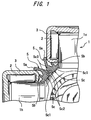
- FIG.1 is a sectional view showing a sealing structure for cross shaft according to a first embodiment of the present invention.
- the figure shows only a quarter (a second quadrant) of a cross shaft (spider).
- the cross shaft 1 is employed by, for example, an automotive steering shaft and used under an environment exposed to water and mud spattered from road surface.
- a vertical shaft 1v and a horizontal shaft 1h 90 degrees shifted in phase constitute the cross shaft 1.
- the vertical and horizontal shafts are each assembled with a cup-shaped outer ring 3 allowed to rotate by needle-like rollers 2.
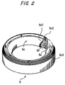
- FIG.2 is a perspective view showing a single body of the seal 5.
- the seal 5 includes lip portions 5a, 5b in contact with the outer ring (rotary ring) 3, and a base 5c supporting these lip portions.
- the base 5c includes a fitting portion 5c1 in contact with the cross shaft 1, a circumferential groove 5c2 having a U-shaped section, and an abutment portion 5c3 at which the seals abut against each other.
- the abutment portion 5c3 is located on the rear side.
- a pair of seals 5 for the vertical shaft 1v and the horizontal shaft 1h form an intersection at positions shown in FIG.1.
- the seals 5 are pressed against each other in back-to-back contact at their abutment portions 5c3. Therefore, the seals can produce a certain frictional force at the contact surfaces thereof.
- the certain frictional force means a frictional force of such a magnitude as to resist a torque of the outer ring 3 to be described hereinlater.
- the abutment portion 5c3 is formed with knurls.
- the seals 5 have their abutment portions 5c3 with the knurls pressed against each other. Therefore, the contact surfaces of the seals have such a great friction coefficient that a sufficient frictional force is produced.
- the circumferential grooves 5c2 positively accommodate to the elastic deformation by changing their form in section. That is, the circumferential grooves 5c2 serve as relief grooves for the deformation caused by the contact pressure between the abutment portions 5c3.
- the elastic deformation caused by the abutment portions 5c3 pressed against each other does not affect the lip portions 5a, 5b, so that the lip portions 5a, 5b are maintained to have a proper contact pressure on the outer ring 3.
- FIG.3 is a front view showing a configuration of the whole body of the cross shaft 1 with the seals 5 fitted thereon in the aforementioned manner.
- the seal 5 receives, from two adjoining seals, torques of an equal value but of the opposite directions as viewed from the respective intersections and besides, is subjected to the sufficient frictional force produced at its abutment portion 5c3 pressed against the abutment portions of the adjoining seals.
- the seal 5 is inhibited from rotating.
- the knurls are formed at the abutment portion 5c3 so as to prevent the occurrence of slippage. Therefore, the rotation of the seal 5 is assuredly inhibited.
- the four seals 5 inhibit one another from rotating without reliance upon the fastness to the cross shaft 1 via the fitting portions 5c1 thereof. Consequently, the seal 5 is prevented from suffering wear associated with its sliding movement against the cross shaft 1. That is, there is provided the sealing structure for cross shaft which is not decreased in the mud/water tightness, although the core bar is obviated for cost down.
- the sectional form of the above seal may be varied in various ways as required.
- the abutment portion 5c3 of the seal 5 for instance, the above embodiment is arranged such that the seals 5 are locked to each other by way of the frictional force produced by pressing against each other at their abutment portions 5c3.
- the abutment portions may be configured to mesh with each other in a gear-like fashion.
- the seal is formed with the circumferential groove 5c2.
- the circumferential groove may be replaced by non-continuous grooves arranged along the circumferential direction of the seal (provided only at necessary places).
- the material for the above seal 5 may be a material having a flexibility suited for the seal and a strength of a degree to permit the transmission of the torque between the seals.
- a usable rubber-base material include NBR, super-nitrile rubber, acrylic rubber and the like.
- a usable resin-base material include polyacetal resin, polyamide resin and the like.
Landscapes
- Engineering & Computer Science (AREA)
- General Engineering & Computer Science (AREA)
- Mechanical Engineering (AREA)
- Sealing Devices (AREA)
- Sealing With Elastic Sealing Lips (AREA)
Applications Claiming Priority (3)
| Application Number | Priority Date | Filing Date | Title |
|---|---|---|---|
| JP2002161830 | 2002-06-03 | ||
| JP2002161830A JP2004011670A (ja) | 2002-06-03 | 2002-06-03 | 十字軸用シール構造 |
| PCT/JP2003/007049 WO2003102435A1 (en) | 2002-06-03 | 2003-06-03 | Seal structure for spider |
Publications (2)
| Publication Number | Publication Date |
|---|---|
| EP1510712A1 true EP1510712A1 (de) | 2005-03-02 |
| EP1510712A4 EP1510712A4 (de) | 2006-03-15 |
Family
ID=29706590
Family Applications (1)
| Application Number | Title | Priority Date | Filing Date |
|---|---|---|---|
| EP03730816A Withdrawn EP1510712A4 (de) | 2002-06-03 | 2003-06-03 | Dichtungskonstruktion für gelenkkreuz |
Country Status (4)
| Country | Link |
|---|---|
| US (1) | US7052401B2 (de) |
| EP (1) | EP1510712A4 (de) |
| JP (1) | JP2004011670A (de) |
| WO (1) | WO2003102435A1 (de) |
Families Citing this family (6)
| Publication number | Priority date | Publication date | Assignee | Title |
|---|---|---|---|---|
| DE10304120A1 (de) * | 2003-01-31 | 2004-09-02 | Voith Turbo Gmbh & Co. Kg | Zapfenkreuz und Kreuzgelenkanordnung |
| JP2006064020A (ja) * | 2004-08-25 | 2006-03-09 | Jtekt Corp | 自在継手 |
| JP4613875B2 (ja) * | 2006-05-16 | 2011-01-19 | 株式会社ジェイテクト | 十字軸継手及びこれを備えた車両用操舵装置 |
| DE102009030372A1 (de) * | 2009-06-25 | 2010-12-30 | Schaeffler Technologies Gmbh & Co. Kg | Am Kreuzgelenkzapfen befestigte Lagerbüchsendichtung |
| DE102014219858B4 (de) * | 2014-09-30 | 2021-09-23 | Aktiebolaget Skf | Kreuzgelenk |
| JP2019082242A (ja) * | 2017-10-27 | 2019-05-30 | 日本精工株式会社 | シールリング、十字軸継手及びステアリング装置 |
Family Cites Families (8)
| Publication number | Priority date | Publication date | Assignee | Title |
|---|---|---|---|---|
| US2903868A (en) * | 1956-04-30 | 1959-09-15 | Fraser Kenneth G | Universal joint and method of making same |
| US3777510A (en) * | 1971-08-12 | 1973-12-11 | Rockwell International Corp | Power transmitting joint arrangement |
| DE2225594B1 (de) * | 1972-05-26 | 1973-08-23 | Uni Cardan AG, 5204 Lohmar | Kreuzgelenk |
| US4283063A (en) * | 1979-05-21 | 1981-08-11 | The Mechanex Corporation | Self aligning installation resistant lubricant seal |
| JPS58214017A (ja) * | 1982-05-06 | 1983-12-13 | エス・カ−・エフ・ク−ゲルラ−ゲルフアブリケン・ゲ−エムベ−ハ− | 軸受ブツシユのための補助シ−ル |
| US5326322A (en) * | 1991-12-09 | 1994-07-05 | Weasler Engineering, Inc. | Cone style universal joint |
| JPH09151956A (ja) * | 1995-11-29 | 1997-06-10 | Ntn Corp | ユニバーサルジョイント |
| US6073933A (en) * | 1998-03-11 | 2000-06-13 | Freudenberg-Nok General Partnership | Load bearing washer and dirt excluder |
-
2002
- 2002-06-03 JP JP2002161830A patent/JP2004011670A/ja not_active Withdrawn
-
2003
- 2003-06-03 WO PCT/JP2003/007049 patent/WO2003102435A1/ja not_active Ceased
- 2003-06-03 US US10/477,428 patent/US7052401B2/en not_active Expired - Fee Related
- 2003-06-03 EP EP03730816A patent/EP1510712A4/de not_active Withdrawn
Also Published As
| Publication number | Publication date |
|---|---|
| EP1510712A4 (de) | 2006-03-15 |
| US20040166947A1 (en) | 2004-08-26 |
| US7052401B2 (en) | 2006-05-30 |
| JP2004011670A (ja) | 2004-01-15 |
| WO2003102435A1 (en) | 2003-12-11 |
Similar Documents
| Publication | Publication Date | Title |
|---|---|---|
| US6296321B1 (en) | Axle unit for driving a vehicle wheel | |
| CA2660873C (en) | Spherical roller bearing sealing assembly | |
| JP2005214421A (ja) | 等速ジョイントのためのボルトレス保持システム | |
| WO2017221582A1 (ja) | 密封装置 | |
| JP7524804B2 (ja) | 転がり軸受装置 | |
| EP0844409B1 (de) | Lagervorrichtung | |
| JP7151533B2 (ja) | ハブユニット軸受 | |
| US6921083B2 (en) | Sealing apparatus and a rolling bearing and a clutch apparatus provided therewith | |
| US7052401B2 (en) | Sealing structure for cross shaft | |
| EP2469134B1 (de) | Einpressvorderdichtung zur Verwendung mit einer Radbaugruppe | |
| JP6517042B2 (ja) | 等速自在継手 | |
| US20220333649A1 (en) | Sealing device | |
| US5653448A (en) | Slinger seal | |
| JP2021518899A (ja) | シール装置、シール材、およびペダルクランク装置 | |
| EP3822503A1 (de) | Dichtungsvorrichtung | |
| JPH0118892Y2 (de) | ||
| EP3990807B1 (de) | Drehfeste dichtung | |
| JP6767810B2 (ja) | 車輪用軸受装置 | |
| JP2012041969A (ja) | 等速自在継手用ブーツ及び等速自在継手 | |
| JP2013204685A (ja) | 自在継手 | |
| JP2018087601A (ja) | スプライン嵌合構造、車輪用軸受装置、およびドライブシャフト | |
| JP5803434B2 (ja) | シール装置付車輪支持用転がり軸受ユニット | |
| US12442411B2 (en) | Sealing device | |
| JP2000274430A (ja) | 車輪駆動用車軸ユニット | |
| JP4330938B2 (ja) | ブーツリング |
Legal Events
| Date | Code | Title | Description |
|---|---|---|---|
| PUAI | Public reference made under article 153(3) epc to a published international application that has entered the european phase |
Free format text: ORIGINAL CODE: 0009012 |
|
| 17P | Request for examination filed |
Effective date: 20040116 |
|
| AK | Designated contracting states |
Kind code of ref document: A1 Designated state(s): DE FR GB IT |
|
| A4 | Supplementary search report drawn up and despatched |
Effective date: 20060201 |
|
| RAP1 | Party data changed (applicant data changed or rights of an application transferred) |
Owner name: JTEKT CORPORATION |
|
| GRAP | Despatch of communication of intention to grant a patent |
Free format text: ORIGINAL CODE: EPIDOSNIGR1 |
|
| STAA | Information on the status of an ep patent application or granted ep patent |
Free format text: STATUS: THE APPLICATION HAS BEEN WITHDRAWN |
|
| 18W | Application withdrawn |
Effective date: 20080806 |