EP3990807B1 - Drehfeste dichtung - Google Patents
Drehfeste dichtung Download PDFInfo
- Publication number
- EP3990807B1 EP3990807B1 EP20731664.7A EP20731664A EP3990807B1 EP 3990807 B1 EP3990807 B1 EP 3990807B1 EP 20731664 A EP20731664 A EP 20731664A EP 3990807 B1 EP3990807 B1 EP 3990807B1
- Authority
- EP
- European Patent Office
- Prior art keywords
- seal
- ring
- load
- extending flange
- seal ring
- Prior art date
- Legal status (The legal status is an assumption and is not a legal conclusion. Google has not performed a legal analysis and makes no representation as to the accuracy of the status listed.)
- Active
Links
Images

Classifications
-
- F—MECHANICAL ENGINEERING; LIGHTING; HEATING; WEAPONS; BLASTING
- F16—ENGINEERING ELEMENTS AND UNITS; GENERAL MEASURES FOR PRODUCING AND MAINTAINING EFFECTIVE FUNCTIONING OF MACHINES OR INSTALLATIONS; THERMAL INSULATION IN GENERAL
- F16J—PISTONS; CYLINDERS; SEALINGS
- F16J15/00—Sealings
- F16J15/16—Sealings between relatively-moving surfaces
- F16J15/34—Sealings between relatively-moving surfaces with slip-ring pressed against a more or less radial face on one member
- F16J15/3436—Pressing means
- F16J15/344—Pressing means the pressing force being applied by means of an elastic ring supporting the slip-ring
-
- B—PERFORMING OPERATIONS; TRANSPORTING
- B62—LAND VEHICLES FOR TRAVELLING OTHERWISE THAN ON RAILS
- B62D—MOTOR VEHICLES; TRAILERS
- B62D55/00—Endless track vehicles
- B62D55/08—Endless track units; Parts thereof
- B62D55/088—Endless track units; Parts thereof with means to exclude or remove foreign matter, e.g. sealing means, self-cleaning track links or sprockets, deflector plates or scrapers
- B62D55/0887—Track-articulation sealings against dust, water, mud or the like
-
- B—PERFORMING OPERATIONS; TRANSPORTING
- B62—LAND VEHICLES FOR TRAVELLING OTHERWISE THAN ON RAILS
- B62D—MOTOR VEHICLES; TRAILERS
- B62D55/00—Endless track vehicles
- B62D55/08—Endless track units; Parts thereof
- B62D55/12—Arrangement, location, or adaptation of driving sprockets
- B62D55/125—Final drives
-
- F—MECHANICAL ENGINEERING; LIGHTING; HEATING; WEAPONS; BLASTING
- F16—ENGINEERING ELEMENTS AND UNITS; GENERAL MEASURES FOR PRODUCING AND MAINTAINING EFFECTIVE FUNCTIONING OF MACHINES OR INSTALLATIONS; THERMAL INSULATION IN GENERAL
- F16J—PISTONS; CYLINDERS; SEALINGS
- F16J15/00—Sealings
- F16J15/16—Sealings between relatively-moving surfaces
- F16J15/32—Sealings between relatively-moving surfaces with elastic sealings, e.g. O-rings
- F16J15/324—Arrangements for lubrication or cooling of the sealing itself
-
- F—MECHANICAL ENGINEERING; LIGHTING; HEATING; WEAPONS; BLASTING
- F16—ENGINEERING ELEMENTS AND UNITS; GENERAL MEASURES FOR PRODUCING AND MAINTAINING EFFECTIVE FUNCTIONING OF MACHINES OR INSTALLATIONS; THERMAL INSULATION IN GENERAL
- F16J—PISTONS; CYLINDERS; SEALINGS
- F16J15/00—Sealings
- F16J15/16—Sealings between relatively-moving surfaces
- F16J15/32—Sealings between relatively-moving surfaces with elastic sealings, e.g. O-rings
- F16J15/3248—Sealings between relatively-moving surfaces with elastic sealings, e.g. O-rings provided with casings or supports
-
- F—MECHANICAL ENGINEERING; LIGHTING; HEATING; WEAPONS; BLASTING
- F16—ENGINEERING ELEMENTS AND UNITS; GENERAL MEASURES FOR PRODUCING AND MAINTAINING EFFECTIVE FUNCTIONING OF MACHINES OR INSTALLATIONS; THERMAL INSULATION IN GENERAL
- F16J—PISTONS; CYLINDERS; SEALINGS
- F16J15/00—Sealings
- F16J15/16—Sealings between relatively-moving surfaces
- F16J15/32—Sealings between relatively-moving surfaces with elastic sealings, e.g. O-rings
- F16J15/3284—Sealings between relatively-moving surfaces with elastic sealings, e.g. O-rings characterised by their structure; Selection of materials
-
- F—MECHANICAL ENGINEERING; LIGHTING; HEATING; WEAPONS; BLASTING
- F16—ENGINEERING ELEMENTS AND UNITS; GENERAL MEASURES FOR PRODUCING AND MAINTAINING EFFECTIVE FUNCTIONING OF MACHINES OR INSTALLATIONS; THERMAL INSULATION IN GENERAL
- F16J—PISTONS; CYLINDERS; SEALINGS
- F16J15/00—Sealings
- F16J15/16—Sealings between relatively-moving surfaces
- F16J15/34—Sealings between relatively-moving surfaces with slip-ring pressed against a more or less radial face on one member
- F16J15/3464—Mounting of the seal
-
- B—PERFORMING OPERATIONS; TRANSPORTING
- B62—LAND VEHICLES FOR TRAVELLING OTHERWISE THAN ON RAILS
- B62D—MOTOR VEHICLES; TRAILERS
- B62D55/00—Endless track vehicles
- B62D55/08—Endless track units; Parts thereof
- B62D55/14—Arrangement, location, or adaptation of rollers
- B62D55/15—Mounting devices, e.g. bushings, axles, bearings, sealings
Definitions
- the present disclosure is directed generally, but not by way of limitation, to seal assemblies, and, more particularly to seal assemblies including metal face seals.
- Machines used in earth moving, agricultural and construction applications are subjected to extreme wear.
- the moving components of such machines need to be provided with a constant supply of lubrication and do so while limiting the loss of that lubrication to the environment and inflow of debris from the worksite into the lubrication supply.
- a seal assembly for retaining lubricant within a sealed cavity and excluding foreign matter from the bearing surfaces between relatively moving parts disposed within the sealed cavity can be used in various components of a machine. Seals are used, for example, in a final drive system, track rollers and idlers of an undercarriage.
- a seal assembly can include a dual face seal.
- a dual face seal can allow a seal to be created over a rotating shaft, such as a spindle, so that one side can remain stationary and the other side can rotate and still maintain an oil seal while keeping debris out.
- the present disclosure is directed to overcoming one or more of the shortcomings set forth above and/or other shortcomings in the art.
- US-A-4421327 discloses a mechanical end face seal assembly with first and second, relatively rigid, primary seal rings of a generally T-shaped cross-section and a pair of annular secondary elastomeric seal rings.
- the secondary rings provide a combination of radial compressive load and axial end face load and are of generally parallelogram shaped cross-section.
- One secondary seal member extends radially outwardly from its associated primary seal ring and the other secondary ring extends radially inwardly from its associated primary ring.
- the present disclosure relates to a dual face seal including a seal ring having an L-shaped cross-section including an axially-extending flange and a radially-extending flange.
- the seal ring has an axially-extending flange and a radially-extending flange defined by a large outer diameter, a small outer diameter and an inner diameter.
- the seal ring further includes an annular seal face and an opposing annular loading surface.
- the annular seal face is configured to seal against a second seal ring in a dual face seal assembly.
- the annular loading surface is configured to receive a load ring.
- the annular loading surface includes a plurality of deformations formed in a spaced apart arrangement circumferentially around the axially-extending flange.
- An axial cross-section through the seal ring and intersecting one of the plurality of deformations includes a stepped geometry such that the small outer diameter has a first small diameter section and a second small diameter section, wherein a first diameter of the first small diameter section is smaller than a second diameter of the second small diameter section.
- the seal assemblies described herein minimize failures by increasing contact area and grip between a load ring having an inner annular surface and a seal ring having deformations in a loading surface to improve the ability to hold to a torque between the load ring and the seal ring.
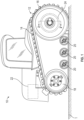
- FIG. 1 illustrates a side elevational view of machine 10 which can include a seal assembly, in accordance with at least one example.
- Machine 10 can include a track-type drive system including a pair of continuous tracks 14 trained around a drive sprocket 16, an idler 18 and rollers 20, which in combination form an undercarriage.
- a motor 22 transfers rotational motion to a final drive system 24 which causes the drive sprocket 16 (e.g., wheel mount) to rotate.
- Rotation of the drive sprocket 16 causes the continuous tracks 14 to move around the drive sprocket 16, idler 18 and rollers 20, enabling movement of the machine 10 relative to a ground surface 1.
- the motor 22 can be any suitable type of power source known in the art, including, but not limited to a diesel-powered, gas-powered, or natural gas-powered engine.
- the motor can also include electric powered, or hybrid power systems.
- the machine 10 can be any suitable machine, such as a general-purpose machine, a tractor such as an agricultural tractor, a skid steer loader, a tracked vehicle such as a military tracked vehicle, a wheel loader, a backhoe, an excavator, a material handler and the like.
- the machine can also be a stationary machine. While the machine 10 is illustrated in the context of a track-type machine, it should be appreciated that the present disclosure is not thereby limited, and that a wide variety of other machines, both those with tracks and without tracks can include features of the seal assemblies described herein.
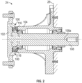
- FIG. 2 illustrates a cross-sectional view of the final drive system 24 of the machine 10 of FIG. 1 taken along line 2-2' (e.g., through a longitudinal axis 108a of a spindle 108), in accordance with at least one example.
- FIG. 2 shows an example of a dual face seal assembly 100 constructed according to principles of the present disclosure that can provide a seal between a first member 102, which in the illustrated example includes a first rotating member such as a drive sprocket 16 or tire mount, and a second non-rotating member 104, which in the illustrated example includes a housing, such as a final drive housing, that is bolted to the machine 10.
- a first member 102 which in the illustrated example includes a first rotating member such as a drive sprocket 16 or tire mount
- a second non-rotating member 104 which in the illustrated example includes a housing, such as a final drive housing, that is bolted to the machine 10.
- the seal assembly 100 which in the illustrative example is a metal-to-metal face seal assembly 100 (e.g., dual face assembly), is disposed in a seal cavity 106 ( FIG. 4 ) extending between the first member 102 and the second member 104.
- the seal assembly 100 can be used to retain lubricant within the seal assembly 100 and to prevent dirt and other contaminants from entering the seal assembly 100.
- the first and second members 102, 104 are rotatable relative to one another about a longitudinal axis 108a of a shaft 108 (e.g., spindle) with the seal assembly 100 providing a means for fluidly sealing the first member 102 and the second member 104 with a running seal therebetween.
- the second member 104 can include a component mounted to a frame 26 of the machine 10 or otherwise stationary with respect to the frame 26, and the first member 102 can comprise a component which is rotatably movable with respect the second member 104 about the longitudinal axis 108a.
- the first member 102 can be stationary and the second member 104 can be rotatable with respect to the frame 26.
- the use of the terms "first”, "second” and the like is used for convenient reference and is not limiting in any way.
- the first member 102 is rotatable about the longitudinal axis 108a with respect to the second member 104.
- the first member 102 and the second member 104 can be disposed in a spaced apart relationship and adjacent one another along the longitudinal axis 108a such that they are separated by a seal gap distance D ( FIG. 4 ).
- the first member 102 and the second member 104 can move axially with respect to each other along the longitudinal axis 108a, thereby varying the seal gap distance D a specified amount.
- the seal assembly 100 includes first and second seal rings 110, 112 and first and second load rings 114, 116, which are all annular.
- the first and second seal rings 110, 112 and the first and second load rings 114, 116 are disposed in the seal cavity 106 between the first member 102 and the second member 104.
- the first and second seal rings 1 10, 112 of the seal assembly 100 are disposed in abutting relationship with each other.
- the first and second seal rings 110, 112 can be substantially identical to each other. Therefore, the description of the first seal ring 110, 112 is applicable to the second seal ring as well. Like the first and second seal rings 110, 112, the first and second load rings 114, 116 can also be substantially identical to each other. Therefore, the description of the first load ring 114 is applicable to the second load ring 116 as well. However, in some examples, the seal rings 110, 112 may not be identical and the load rings 114, 116 may not be not identical.
- the first and second load rings 114, 116 are respectively mounted to the first and second seal rings 110, 112.
- the first and second seal rings 110, 112 can be made from any suitable material, such as, but not limited to, metal, a metal alloy, a ceramic material and combinations thereof.
- the first and second load rings 114, 116 can be made from a suitable elastomeric material such as, but not limited to nitrile, silicone, or a fluoroelastomer, and combinations thereof.
- the seal assembly 100 provides a dual face seal in the form of first and second seal rings 110, 112.
- the first load ring 114 acts as a gasket and sealingly engages the first member 102 and the first seal ring 110 to provide a fluid-tight seal therebetween.
- the second load ring 116 acts as a gasket and sealing engages the second member 104 and the second seal ring 116 to provide a fluid tight seal therebetween.
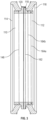
- FIG. 3 illustrates a cross-sectional view of the first and second seal rings 110, 112 and first and second load rings 114, 116 taken along line 2-2' in FIG. 2 , in accordance with at least one example.
- the first and second seal rings 110, 112 can each be in the form of an annulus.
- the first seal ring 110 and the second seal ring 112 can abut one another such that seal faces 118, 120 of the first seal ring 110 and the second seal ring 112 are in contacting relationship with each other.
- first seal ring 110 and the first load ring 114 in a fixed relationship with each other and the second seal ring 112 and the second load ring 116 in a fixed relationship with each.
- first seal ring 110 and the second seal ring 112 rotate relative to one another with the closest point of contact being along the first and second seal faces 118, 120.
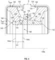
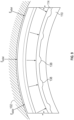
- FIG. 4 illustrates a close-up view of a portion of the example seal assembly of FIG. 2 .
- Each of the first member 102 and the second member 104 includes a load ring engagement surface (first and second load ring engagement surfaces 122, 124).
- the load ring engagement surfaces 122, 124 of the first member 102 and the second member 104 define, at least in part, the seal cavity 106, which extends axially along the longitudinal axis 108a between the first member and the second member.
- the load ring engagement surfaces 122, 124 are generally annular and are coaxial with the longitudinal axis 108a. In the illustrated example, the load ring engagement surfaces 122, 124 each maintains the respective cross-sectional shape shown in FIG. 2 substantially continuously over the entire circumference circumscribed around the longitudinal axis 108a by the first and second members 102, 104.
- each seal ring 110, 112 has an L-shaped cross-section including an axially-extending flange 126 and a radially extending flange 128.
- Each seal ring 110, 112 is defined by a large outer diameter 162, a small outer diameter and an inner diameter 146
- Each seal ring 110, 112 further includes an annular seal face 118, 120 and an opposing annular loading surface 134, 136 which is configured to receive the corresponding first or second load ring 114, 116.
- Each of the seal faces 118, 120 are defined by the radially-extending flange 128 which extends radially away from the longitudinal axis 108a of shaft 108 (shaft 108 not fully shown in FIG. 4 , also see FIG. 3 ).
- the seal faces 118, 120 of the first and second seal rings 110, 112 form a radially-extending annulus and are in a sealing relationship with each other.
- Each seal face 118, 120 can extend radially to an outer perimeter 130.
- the first and second seal rings abut one another such that at least a portion of the first and second seal rings 110, 112 are in contacting relationship with each other to define a band 132 of contact between the seal faces 118, 120.
- Axial loading of the first and second seal rings 110, 112 along the longitudinal axis 108a. is accomplished by means of the first and second load rings 114, 116.
- the first and second load rings 114, 116 resiliently support the first and second seal rings 110, 112, respectively.
- First and second loading surfaces 134, 136 are formed along the first and second seal rings 110, 112 to receive the first and second load rings 114, 116, respectively.
- the first loading surface 134 is formed by radially-extending flange 126 and an axially-extending flange 140.
- the second loading surface 136 is formed by the radially-extending flange 28 and a second axially-extending flange 142.
- the first load ring 114 engages the first loading surface 134 of the first seal ring 110
- the second load ring 116 engages the second loading surface 136 of the second seal ring 1 12.
- the load ring engagement surface 122 of the first member 102 and the loading surface 134 of the first seal ring 110 are in confronting, spaced apart relationship such that they compress the first load ring 114 therebetween when in an assembled state (e.g., compressed state).
- the load ring engagement surface 124 of the second member 104 and the loading surface 136 of the second seal ring 112 are in confronting, spaced apart relationship such that they compress the second load ring 116 therebetween when in the assembled state.
- the load ring engagement surfaces 122, 124 of the first and second members 102, 104 are positioned in corresponding confronting (e.g., opposing) relationship with respect to the loading surfaces 134, 136 of the first and second seal rings 110, 112 so as to contain and compress the first and second load rings 114, 116 therebetween.
- Axial loading of the first and second seal rings 110, 112 is thus accomplished through the axial loading of the first and second load rings 114, 116 by the first and second members 102, 104.
- the first and second load rings 114, 116 resiliently support the first and second seal rings 110, 112 and drive the seal faces 118, 120 of the first and second seal rings 110, 112 together to define the band 132 of contact between the seal rings 110, 112.
- the first and second load rings 114, 116 act in the manner of a spring to apply an axial load respectively against the first and second seal rings 110, 112 in opposing directions along the longitudinal axis 108a to bring the seal faces 118, 120 of the first and second seal rings 110, 112 into face-to-face sealing contact under pressure along the band 132 of contact such that a running, fluid tight seal is formed.
- each of the load rings 114, 116 can include an inner annular surface 144 and an outer annular surface 148 that are concentrically disposed about the longitudinal axis 108a.
- both the inner annular surface 144 and the outer annular surface 148 of the load ring 114 can be substantially parallel to the longitudinal axis 108a and/or each other and extend axially.
- the load rings 114, 116 can extend in an axial direction from an inner radial surface 150 to an outer radial surface 152.
- the first and second seal rings 110, 112 are rotatably movable with respect to each other about the longitudinal axis 108a.
- the second seal ring 112 can be considered a stationary seal ring as it is rotatably coupled through the second load ring 116 with the second member 104.
- the first seal ring 110 can be considered a rotational seal ring as it is coupled through the first load ring 114 with the first member 102.
- the first member 102 can be a sprocket or wheel mount 16 ( FIG. 1 ) that is rotatably mounted to the second member 104 such that the sprocket or wheel mount 16 can rotate about the longitudinal axis 108a relative to the second member 104.
- the first load ring 114 engages the first loading surface 134 of the first seal ring 110
- the second load ring 116 engages the second loading surface 136 of the second seal ring 112.
- rotation e.g., spinning
- rotation of the second load ring 116 relative to the to the second seal ring 112 at the second loading surface 136.
- a plurality of deformations 138 are formed in spaced apart arrangement circumferentially around the seal rings 110, 112.
- the deformations 138 are formed in the loading surfaces 134, 136 of the axially-extending flanges 140, 142.
- the axially-extending flange 140 can extend a length 141 from an inner end 166 to an outer end 168.
- an axial cross-section through the axially-extending flange 140 and through one of the deformations 138 is including a stepped geometry or stepped diameter along the axially-extending flange 140.
- the stepped geometry can be described as the first loading surface 134 having a stepped small outer diameter.
- the stepped small outer diameter includes a first small outer diameter 164a and a second small outer diameter 164b ( FIG. 3 ). Both the first and second small outer diameters 164a, 164b can be considered small compared to large outer diameter 162 of the radially-extending flange 126.
- the deformations 138 can be located distal from the radially extending flange 126 proximate the outer end 168. In other examples, the deformations 138 can be positioned in another location along the length 141 of the axially-extending flange 140. For example, the deformations 138 could be located proximate the radially-extending flange 126.
- the first small outer diameter 164a can extend between 25-75% of the length 141 of the axially-extending flange 140. In some examples the second small outer diameter 164b can extend 25-75% of the length of the axially-extending flange 140.
- each of the first small outer diameter 146a and the second small outer diameter 164b extends about 50% of the length 141 of the axially-extending flange 140 (each being within a range of ⁇ 20%, or possibly more preferably within a range of ⁇ 10%).
- the interaction of the deformations 138 in the seal rings 110, 112 and the interaction with the load rings 114, 116 will be described further in FIGS. 5-9 .
- the load rings 114, 116 have a smooth inner annular surface 144 defined by a constant diameter 146 (e.g., substantially constant).
- the example load ring 14, 116 does not include complementary deformations along the inner annular surface 144 of the load rings 114, 116 to interface with deformations 138 in the seal rings 10, 112.
- the load rings 114, 116 can include an inner annular surface 144 having constant diameter 146 ( FIG. 3 ) and a uniform inner annular surface 144 dimension, or at least a uniform inner annular surface 144 in the region of the load ring 114, 116 that interfaces with the deformations 138 in seal ring 110, 112.
- the load ring 114, 116 may not have a completely uniform inner diameter 146 ( FIG. 3 ), but any deformations or non-uniformity that is present in the load rings 114, 116 does not necessarily interface in a complementary shape and manner with the deformations 138 in the seal rings 110, 112.
- the illustrative load rings 114, 116 in some examples do not include complementary geometry to fill the deformations 138 in the seal rings 110, 112, when the load rings 114, 116 are loaded onto the seal rings 110, 112 and compressed in an assembled state ( FIG. 4 , FIG. 9 ) by the first and second members 102, 104, the load rings 114, 116 are compressed against the seal rings 110, 112. Under the compressive force of the first and second members 102, 104, portions of the load rings 114, 116 are distorted and deformed into (e.g., protrude into, squeeze into) the deformations 138. This interface between the respective load rings 114, 116 and the seal rings 110, 112 can improve grip and sealing and reduce tearing of load rings 114, 116 over conventional seal assemblies.
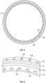
- FIG. 5 illustrates an axial view of the example seal rings 110, 12 (112 is hidden from view) of FIG. 2
- FIG. 6 is a perspective view of a portion of the seal rings 110, 112.
- deformations 138 are understood to mean features which recess into a defined surface or extend outward away from a defined surface.
- the defined surface can include for example, a ring shape, such as the loading surface of the seal rings 110, 112.
- the deformations 138 are shown as depressions, however the deformations 138 can also include raised deformations.
- FIG. 7 illustrates an axial view of the example load ring 114 and seal ring 110 of FIG. 2 in an uncompressed state.
- FIG. 8 illustrates a close-up view of a portion of FIG. 7.
- FIGS. 7 and 8 both illustrate how the load ring 114 may not include deformations that extend into the deformations 138 in the seal ring 110.
- FIG. 9 illustrates a close-up view of the load ring 114 and seal ring 110 of FIGS. 7 and 8 , but in an assembled (e.g., compressed state).
- the load ring 114 In the compressed state, the load ring 114 is distorted such that the load ring 114 extends into and fills a portion of the deformations 138 in the seal ring 110.
- the distortion e.g., squeezing, pushing, stretching
- F radial FIGS. 4 and 9
- F axial FIG. 4
- grip between the load ring 114 and the seal ring 110 are improved because the amount of surface area of the load ring 114 that is in contact with the seal ring 110 is increased.
- One benefit of an example including providing the load ring 114 without complementary deformations is that there are no small features extending radially inward from the load ring 114 towards the seal ring 110 that can be sheared off under torque between the load ring 114 and seal ring 110.
- the seal assembly 100 can be used to provide a rotating seal over a spindle 108 at the connection between a final drive housing (e.g., second member 104) that is mounted to a frame 26 of the track-type vehicle 10 and a rotating drive sprocket or wheel mount (e.g., first member 102).
- a final drive housing e.g., second member 104
- a rotating drive sprocket or wheel mount e.g., first member 102
- seal assemblies 100 including seal rings 1 10, 112 and load rings 114, 116 described herein include an improvement in torque resistance in a dual face seal assembly.
- the dual face seal assembly can be configured to allow an elastomeric load ring 114 disposed between the seal ring 110 and the final drive housing 104, to squeeze into a plurality of deformations 138 in the seal ring 110 and to form more bonding over a larger surface area than the unstressed surface area of the load ring 114, thus providing resistance to spinning of the load ring 114 relative to either the seal ring 110 or the final drive housing 104.
Landscapes
- Engineering & Computer Science (AREA)
- General Engineering & Computer Science (AREA)
- Mechanical Engineering (AREA)
- Chemical & Material Sciences (AREA)
- Combustion & Propulsion (AREA)
- Transportation (AREA)
- Sealing Devices (AREA)
- Mechanical Sealing (AREA)
Claims (10)
- Doppelgleitringdichtung, umfassend:einen Dichtungsring (110), der einen L-förmigen Querschnitt aufweist, der einen axial verlaufenden Flansch (140) und einen radial verlaufenden Flansch (126) einschließt, wobei der Dichtungsring (110) den axial verlaufenden Flansch (140) und den radial verlaufenden Flansch (126) einschließt, die durch einen großen Außendurchmesser (162), einen kleinen Außendurchmesser (164a) und einen Innendurchmesser (146) definiert sind, wobei der Dichtungsring (110) ferner eine ringförmige Dichtungsfläche (118) und eine gegenüberliegende ringförmige Belastungsoberfläche (134) einschließt,wobei die ringförmige Dichtungsfläche (118) konfiguriert ist, um in einer Doppelgleitringdichtungsanordnung (100) gegen einen zweiten Dichtungsring (112) abzudichten,wobei die ringförmige Belastungsoberfläche (134) konfiguriert ist, um einen Lastring (114) aufzunehmen, und wobei die ringförmige Belastungsoberfläche (134) eine Vielzahl von Verformungen (138) einschließt, die in einer beabstandeten Anordnung um den axial verlaufenden Flansch (140) kreisförmig ausgebildet sind, dadurch gekennzeichnet, dassein axialer Querschnitt durch den Dichtungsring (110), und der eine der Vielzahl von Verformungen (138) schneidet, eine abgestufte Geometrie derart einschließt, dass der kleine Außendurchmesser einen ersten Abschnitt mit kleinem Durchmesser und einen zweiten Abschnitt mit kleinem Durchmesser aufweist, ferner dadurch gekennzeichnet, dassein erster Durchmesser (164a) des ersten Abschnitts mit kleinem Durchmesser kleiner als ein zweiter Durchmesser (164b) des zweiten Abschnitts mit kleinem Durchmesser ist.
- Doppelgleitringdichtung nach Anspruch 1, wobei jede der Vielzahl von Verformungen (138) konfiguriert ist, um zu ermöglichen, dass der Lastring (114) sich in die Vielzahl von Verformungen (138) hineinzwängt, um eine Verbindung zwischen dem Dichtungsring (110) und dem Lastring (114) über einen vergrößerten Oberflächenbereich auszubilden, um einen Widerstand gegen eine relative Drehung zwischen dem Dichtungsring (110) und dem Lastring (114) bereitzustellen.
- Doppelgleitringdichtung nach Anspruch 1, wobei der zweite Abschnitt mit kleinem Durchmesser (z. B. 164a) sich näher an dem radial verlaufenden Flansch (126) als der erste Abschnitt mit kleinem Durchmesser (z. B. 164b) befindet.
- Doppelgleitringdichtung nach Anspruch 1, wobei der erste Abschnitt mit kleinem Durchmesser (z. B. 164a) sich näher an dem radial verlaufenden Flansch (126) als der zweite Abschnitt mit kleinem Durchmesser (z. B. 164b) befindet.
- Doppelgleitringdichtung nach Anspruch 1, wobei die Verformungen (138) zu 25-75 % einer Länge (141) des axial verlaufenden Flansches (140) verlaufen.
- Doppelgleitringdichtung nach Anspruch 1, wobei die Doppelgleitringdichtung (110) konfiguriert ist, um in eine Doppelgleitringdichtungsanordnung (100) integriert zu werden, um eine Drehverbindung in einem Achsantriebssystem (24) eines Kettenfahrzeugs (10) abzudichten.
- Doppelgleitringdichtung (100), umfassend:eine Doppelgleitringdichtung nach Anspruch 1; undeinen zweiten Dichtungsring (112), der einen L-förmigen Querschnitt aufweist, wobei der zweite Dichtungsring (112) einen axial verlaufenden Flansch (142) und einen radial verlaufenden Flansch (128) einschließt, die durch einen großen Außendurchmesser (162), einen kleinen Außendurchmesser (164b) und einen Innendurchmesser (146) definiert sind, wobei der erste Dichtungsring (110) und der zweite Dichtungsring (120) einander zugewandte ringförmige Dichtungsflächen (118, 120) und gegenüberliegende ringförmige Belastungsoberflächen (122, 124) aufweisen; undeinen ersten Lastring (114) und einen zweiten Lastring (116), wobei jeder des ersten Lastrings (114) und des zweiten Lastrings (116) einem des ersten Dichtungsrings (110) beziehungsweise des zweiten Dichtungsrings (112) entsprechen, wobei jeder des ersten und des zweiten Lastrings (110, 112) eine innere ringförmige Oberfläche (144) aufweist, wobei die innere ringförmige Oberfläche (144) jedes des ersten und des zweiten Lastrings (114, 116) konfiguriert ist, um mit der ringförmigen Belastungsoberfläche (122, 124) des entsprechenden ersten oder entsprechenden zweiten Dichtungsrings (110, 112) in Eingriff zu treten und eine Kraft auf diese auszuüben, um die Dichtungsflächen (118, 120) in dichtendem Eingriff zu halten.
- Doppelgleitringdichtung (100) nach Anspruch 7, ferner umfassend ein erstes Element (102), das den ersten Lastring (114) umgibt und eine Druckkraft auf diesen derart ausübt, dass mindestens ein Anteil des ersten Lastrings (114) in die Vielzahl von Verformungen (138) in dem ersten Dichtungsring (110) hineingezwängt wird, wobei veranlasst wird, dass der erste Lastring (114) derart verformt wird, dass die Verbindung zwischen dem ersten Lastring (114) und dem ersten Dichtungsring (110) über einen größeren Oberflächenbereich des ersten Lastrings (114) auftritt, als wenn die Druckkraft (F) nicht ausgeübt wird.
- Doppelgleitringdichtung (100) nach Anspruch 7, wobei die innere ringförmige Oberfläche (144) des ersten Lastrings (114) einen konstanten Durchmesser aufweist.
- Doppelgleitringdichtung (100) nach Anspruch 7, wobei der zweite Abschnitt mit kleinem Durchmesser (z. B. 164b) näher an dem radial verlaufenden Flansch (126) als der erste Abschnitt mit kleinem Durchmesser (z. B. 164a) liegt.
Applications Claiming Priority (2)
| Application Number | Priority Date | Filing Date | Title |
|---|---|---|---|
| US16/452,210 US11592111B2 (en) | 2019-06-25 | 2019-06-25 | Torque resistant seal |
| PCT/US2020/033347 WO2020263454A1 (en) | 2019-06-25 | 2020-05-18 | Torque resistant seal |
Publications (2)
| Publication Number | Publication Date |
|---|---|
| EP3990807A1 EP3990807A1 (de) | 2022-05-04 |
| EP3990807B1 true EP3990807B1 (de) | 2025-02-19 |
Family
ID=71069971
Family Applications (1)
| Application Number | Title | Priority Date | Filing Date |
|---|---|---|---|
| EP20731664.7A Active EP3990807B1 (de) | 2019-06-25 | 2020-05-18 | Drehfeste dichtung |
Country Status (9)
| Country | Link |
|---|---|
| US (1) | US11592111B2 (de) |
| EP (1) | EP3990807B1 (de) |
| KR (1) | KR102704026B1 (de) |
| CN (1) | CN114096769A (de) |
| AU (1) | AU2020305728A1 (de) |
| BR (1) | BR112021025162A2 (de) |
| CA (1) | CA3143182A1 (de) |
| PE (1) | PE20220229A1 (de) |
| WO (1) | WO2020263454A1 (de) |
Families Citing this family (1)
| Publication number | Priority date | Publication date | Assignee | Title |
|---|---|---|---|---|
| US11667340B2 (en) * | 2020-03-06 | 2023-06-06 | Caterpillar Inc. | Screw profile mud-packing preventing |
Family Cites Families (16)
| Publication number | Priority date | Publication date | Assignee | Title |
|---|---|---|---|---|
| US4183542A (en) * | 1977-10-21 | 1980-01-15 | Fonderia R. Bertoldo & C. S.a.s. | Rotating face sealing gasket, particularly for use on tracked vehicles |
| US4256315A (en) | 1979-10-22 | 1981-03-17 | Cr Industries | Mechanical end face seal with dirt excluder lip |
| US4421327A (en) | 1981-12-17 | 1983-12-20 | Morley James P | Heavy duty end face seal with asymmetrical cross-section |
| US4560174A (en) | 1983-12-02 | 1985-12-24 | Berco S.P.A. | Multi lip seal |
| USH1180H (en) * | 1991-12-23 | 1993-05-04 | Caterpillar Inc. | Face seal with increased torque transfer capacity |
| WO1999031411A1 (en) | 1997-12-12 | 1999-06-24 | Caterpillar Inc. | Face seal assembly with interfitting load ring |
| US6186511B1 (en) | 1998-11-17 | 2001-02-13 | Caterpillar Inc. | Seal assembly with an interlocking load ring |
| DE10104788C2 (de) * | 2001-02-02 | 2003-06-26 | Federal Mogul Friedberg Gmbh | Gleitringdichtung mit radialer Verdrehsicherung |
| DE10238166B4 (de) * | 2002-08-21 | 2004-08-05 | Federal-Mogul Friedberg Gmbh | Gleitringdichtung |
| US8205891B2 (en) | 2008-09-15 | 2012-06-26 | Stein Seal Company | Intershaft seal assembly |
| DE102008049911B4 (de) * | 2008-10-02 | 2023-05-04 | Ab Skf | Dichtungsanordnung und Gelenk einer Kette mit der Dichtungsanordnung |
| DE102009058216B4 (de) | 2009-12-15 | 2014-09-04 | Aktiebolaget Skf | Dichtungsanordnung und Gelenk einer Kette mit der Dichtungsanordnung |
| US20140131952A1 (en) | 2012-11-15 | 2014-05-15 | Caterpillar Global Mining Llc | Adjustable face seal assembly |
| US9714713B2 (en) * | 2012-12-20 | 2017-07-25 | Caterpillar Inc. | Seal ring with frictional load surface |
| US9353866B2 (en) | 2014-04-17 | 2016-05-31 | Caterpillar Inc. | Seal assembly with complementary surface deformations |
| US9822883B2 (en) * | 2015-12-01 | 2017-11-21 | Caterpillar Inc. | Load ring for seal assembly and seal assembly of machine |
-
2019
- 2019-06-25 US US16/452,210 patent/US11592111B2/en active Active
-
2020
- 2020-05-18 EP EP20731664.7A patent/EP3990807B1/de active Active
- 2020-05-18 CN CN202080044628.5A patent/CN114096769A/zh active Pending
- 2020-05-18 KR KR1020227002090A patent/KR102704026B1/ko active Active
- 2020-05-18 AU AU2020305728A patent/AU2020305728A1/en not_active Abandoned
- 2020-05-18 WO PCT/US2020/033347 patent/WO2020263454A1/en not_active Ceased
- 2020-05-18 PE PE2021002068A patent/PE20220229A1/es unknown
- 2020-05-18 CA CA3143182A patent/CA3143182A1/en active Pending
- 2020-05-18 BR BR112021025162A patent/BR112021025162A2/pt not_active IP Right Cessation
Also Published As
| Publication number | Publication date |
|---|---|
| AU2020305728A1 (en) | 2022-02-03 |
| US11592111B2 (en) | 2023-02-28 |
| PE20220229A1 (es) | 2022-02-07 |
| KR20220024809A (ko) | 2022-03-03 |
| EP3990807A1 (de) | 2022-05-04 |
| KR102704026B1 (ko) | 2024-09-09 |
| WO2020263454A1 (en) | 2020-12-30 |
| CN114096769A (zh) | 2022-02-25 |
| BR112021025162A2 (pt) | 2022-01-25 |
| US20200406995A1 (en) | 2020-12-31 |
| CA3143182A1 (en) | 2020-12-30 |
Similar Documents
| Publication | Publication Date | Title |
|---|---|---|
| EP2552766B1 (de) | Dichtungsbaugruppe für eine spurstift-gelenkbaugruppe | |
| CA2793988C (en) | Seal assembly for track pin joint assembly | |
| WO2013026061A2 (en) | Pin joint having an elastomeric bushing | |
| AU2014311405B2 (en) | Seal assembly for track pin joint assembly of undercarriage | |
| EP3990807B1 (de) | Drehfeste dichtung | |
| US20120163904A1 (en) | Seal assembly for pin joint | |
| US9822883B2 (en) | Load ring for seal assembly and seal assembly of machine | |
| EP2655173B1 (de) | Dichtungsanordnung | |
| US6186511B1 (en) | Seal assembly with an interlocking load ring | |
| US20200079445A1 (en) | Lip Seal | |
| US11499637B2 (en) | Lip seal | |
| JP2024530160A (ja) | トラックリンクジョイント用ラジアルシール | |
| JP2003222247A (ja) | メカニカルシール |
Legal Events
| Date | Code | Title | Description |
|---|---|---|---|
| STAA | Information on the status of an ep patent application or granted ep patent |
Free format text: STATUS: UNKNOWN |
|
| STAA | Information on the status of an ep patent application or granted ep patent |
Free format text: STATUS: THE INTERNATIONAL PUBLICATION HAS BEEN MADE |
|
| PUAI | Public reference made under article 153(3) epc to a published international application that has entered the european phase |
Free format text: ORIGINAL CODE: 0009012 |
|
| STAA | Information on the status of an ep patent application or granted ep patent |
Free format text: STATUS: REQUEST FOR EXAMINATION WAS MADE |
|
| 17P | Request for examination filed |
Effective date: 20211201 |
|
| AK | Designated contracting states |
Kind code of ref document: A1 Designated state(s): AL AT BE BG CH CY CZ DE DK EE ES FI FR GB GR HR HU IE IS IT LI LT LU LV MC MK MT NL NO PL PT RO RS SE SI SK SM TR |
|
| DAV | Request for validation of the european patent (deleted) | ||
| DAX | Request for extension of the european patent (deleted) | ||
| GRAP | Despatch of communication of intention to grant a patent |
Free format text: ORIGINAL CODE: EPIDOSNIGR1 |
|
| STAA | Information on the status of an ep patent application or granted ep patent |
Free format text: STATUS: GRANT OF PATENT IS INTENDED |
|
| INTG | Intention to grant announced |
Effective date: 20240821 |
|
| GRAS | Grant fee paid |
Free format text: ORIGINAL CODE: EPIDOSNIGR3 |
|
| P01 | Opt-out of the competence of the unified patent court (upc) registered |
Free format text: CASE NUMBER: APP_63005/2024 Effective date: 20241127 |
|
| GRAA | (expected) grant |
Free format text: ORIGINAL CODE: 0009210 |
|
| STAA | Information on the status of an ep patent application or granted ep patent |
Free format text: STATUS: THE PATENT HAS BEEN GRANTED |
|
| AK | Designated contracting states |
Kind code of ref document: B1 Designated state(s): AL AT BE BG CH CY CZ DE DK EE ES FI FR GB GR HR HU IE IS IT LI LT LU LV MC MK MT NL NO PL PT RO RS SE SI SK SM TR |
|
| REG | Reference to a national code |
Ref country code: GB Ref legal event code: FG4D |
|
| REG | Reference to a national code |
Ref country code: CH Ref legal event code: EP |
|
| REG | Reference to a national code |
Ref country code: DE Ref legal event code: R096 Ref document number: 602020046303 Country of ref document: DE |
|
| REG | Reference to a national code |
Ref country code: IE Ref legal event code: FG4D |
|
| REG | Reference to a national code |
Ref country code: NL Ref legal event code: MP Effective date: 20250219 |
|
| PG25 | Lapsed in a contracting state [announced via postgrant information from national office to epo] |
Ref country code: RS Free format text: LAPSE BECAUSE OF FAILURE TO SUBMIT A TRANSLATION OF THE DESCRIPTION OR TO PAY THE FEE WITHIN THE PRESCRIBED TIME-LIMIT Effective date: 20250519 |
|
| PG25 | Lapsed in a contracting state [announced via postgrant information from national office to epo] |
Ref country code: FI Free format text: LAPSE BECAUSE OF FAILURE TO SUBMIT A TRANSLATION OF THE DESCRIPTION OR TO PAY THE FEE WITHIN THE PRESCRIBED TIME-LIMIT Effective date: 20250219 |
|
| PG25 | Lapsed in a contracting state [announced via postgrant information from national office to epo] |
Ref country code: PL Free format text: LAPSE BECAUSE OF FAILURE TO SUBMIT A TRANSLATION OF THE DESCRIPTION OR TO PAY THE FEE WITHIN THE PRESCRIBED TIME-LIMIT Effective date: 20250219 |
|
| PG25 | Lapsed in a contracting state [announced via postgrant information from national office to epo] |
Ref country code: ES Free format text: LAPSE BECAUSE OF FAILURE TO SUBMIT A TRANSLATION OF THE DESCRIPTION OR TO PAY THE FEE WITHIN THE PRESCRIBED TIME-LIMIT Effective date: 20250219 |
|
| REG | Reference to a national code |
Ref country code: LT Ref legal event code: MG9D |
|
| PG25 | Lapsed in a contracting state [announced via postgrant information from national office to epo] |
Ref country code: NO Free format text: LAPSE BECAUSE OF FAILURE TO SUBMIT A TRANSLATION OF THE DESCRIPTION OR TO PAY THE FEE WITHIN THE PRESCRIBED TIME-LIMIT Effective date: 20250519 Ref country code: IS Free format text: LAPSE BECAUSE OF FAILURE TO SUBMIT A TRANSLATION OF THE DESCRIPTION OR TO PAY THE FEE WITHIN THE PRESCRIBED TIME-LIMIT Effective date: 20250619 |
|
| PG25 | Lapsed in a contracting state [announced via postgrant information from national office to epo] |
Ref country code: NL Free format text: LAPSE BECAUSE OF FAILURE TO SUBMIT A TRANSLATION OF THE DESCRIPTION OR TO PAY THE FEE WITHIN THE PRESCRIBED TIME-LIMIT Effective date: 20250219 |
|
| PGFP | Annual fee paid to national office [announced via postgrant information from national office to epo] |
Ref country code: IT Payment date: 20250520 Year of fee payment: 6 |
|
| PG25 | Lapsed in a contracting state [announced via postgrant information from national office to epo] |
Ref country code: HR Free format text: LAPSE BECAUSE OF FAILURE TO SUBMIT A TRANSLATION OF THE DESCRIPTION OR TO PAY THE FEE WITHIN THE PRESCRIBED TIME-LIMIT Effective date: 20250219 |
|
| PG25 | Lapsed in a contracting state [announced via postgrant information from national office to epo] |
Ref country code: PT Free format text: LAPSE BECAUSE OF FAILURE TO SUBMIT A TRANSLATION OF THE DESCRIPTION OR TO PAY THE FEE WITHIN THE PRESCRIBED TIME-LIMIT Effective date: 20250620 Ref country code: LV Free format text: LAPSE BECAUSE OF FAILURE TO SUBMIT A TRANSLATION OF THE DESCRIPTION OR TO PAY THE FEE WITHIN THE PRESCRIBED TIME-LIMIT Effective date: 20250219 |
|
| PG25 | Lapsed in a contracting state [announced via postgrant information from national office to epo] |
Ref country code: GR Free format text: LAPSE BECAUSE OF FAILURE TO SUBMIT A TRANSLATION OF THE DESCRIPTION OR TO PAY THE FEE WITHIN THE PRESCRIBED TIME-LIMIT Effective date: 20250520 Ref country code: BG Free format text: LAPSE BECAUSE OF FAILURE TO SUBMIT A TRANSLATION OF THE DESCRIPTION OR TO PAY THE FEE WITHIN THE PRESCRIBED TIME-LIMIT Effective date: 20250219 |
|
| PGFP | Annual fee paid to national office [announced via postgrant information from national office to epo] |
Ref country code: TR Payment date: 20250428 Year of fee payment: 6 |
|
| REG | Reference to a national code |
Ref country code: AT Ref legal event code: MK05 Ref document number: 1768527 Country of ref document: AT Kind code of ref document: T Effective date: 20250219 |
|
| PG25 | Lapsed in a contracting state [announced via postgrant information from national office to epo] |
Ref country code: SE Free format text: LAPSE BECAUSE OF FAILURE TO SUBMIT A TRANSLATION OF THE DESCRIPTION OR TO PAY THE FEE WITHIN THE PRESCRIBED TIME-LIMIT Effective date: 20250219 |
|
| PG25 | Lapsed in a contracting state [announced via postgrant information from national office to epo] |
Ref country code: SM Free format text: LAPSE BECAUSE OF FAILURE TO SUBMIT A TRANSLATION OF THE DESCRIPTION OR TO PAY THE FEE WITHIN THE PRESCRIBED TIME-LIMIT Effective date: 20250219 |
|
| PG25 | Lapsed in a contracting state [announced via postgrant information from national office to epo] |
Ref country code: DK Free format text: LAPSE BECAUSE OF FAILURE TO SUBMIT A TRANSLATION OF THE DESCRIPTION OR TO PAY THE FEE WITHIN THE PRESCRIBED TIME-LIMIT Effective date: 20250219 |
|
| PG25 | Lapsed in a contracting state [announced via postgrant information from national office to epo] |
Ref country code: AT Free format text: LAPSE BECAUSE OF FAILURE TO SUBMIT A TRANSLATION OF THE DESCRIPTION OR TO PAY THE FEE WITHIN THE PRESCRIBED TIME-LIMIT Effective date: 20250219 |
|
| PG25 | Lapsed in a contracting state [announced via postgrant information from national office to epo] |
Ref country code: EE Free format text: LAPSE BECAUSE OF FAILURE TO SUBMIT A TRANSLATION OF THE DESCRIPTION OR TO PAY THE FEE WITHIN THE PRESCRIBED TIME-LIMIT Effective date: 20250219 Ref country code: CZ Free format text: LAPSE BECAUSE OF FAILURE TO SUBMIT A TRANSLATION OF THE DESCRIPTION OR TO PAY THE FEE WITHIN THE PRESCRIBED TIME-LIMIT Effective date: 20250219 |
|
| PG25 | Lapsed in a contracting state [announced via postgrant information from national office to epo] |
Ref country code: RO Free format text: LAPSE BECAUSE OF FAILURE TO SUBMIT A TRANSLATION OF THE DESCRIPTION OR TO PAY THE FEE WITHIN THE PRESCRIBED TIME-LIMIT Effective date: 20250219 |
|
| PG25 | Lapsed in a contracting state [announced via postgrant information from national office to epo] |
Ref country code: SK Free format text: LAPSE BECAUSE OF FAILURE TO SUBMIT A TRANSLATION OF THE DESCRIPTION OR TO PAY THE FEE WITHIN THE PRESCRIBED TIME-LIMIT Effective date: 20250219 |