EP1510696B1 - Selbstansaugende Kreiselpumpe - Google Patents
Selbstansaugende Kreiselpumpe Download PDFInfo
- Publication number
- EP1510696B1 EP1510696B1 EP03425564A EP03425564A EP1510696B1 EP 1510696 B1 EP1510696 B1 EP 1510696B1 EP 03425564 A EP03425564 A EP 03425564A EP 03425564 A EP03425564 A EP 03425564A EP 1510696 B1 EP1510696 B1 EP 1510696B1
- Authority
- EP
- European Patent Office
- Prior art keywords
- diffusion chamber
- sector
- self
- wall
- chamber
- Prior art date
- Legal status (The legal status is an assumption and is not a legal conclusion. Google has not performed a legal analysis and makes no representation as to the accuracy of the status listed.)
- Expired - Lifetime
Links
- 238000009792 diffusion process Methods 0.000 claims abstract description 45
- 239000007788 liquid Substances 0.000 claims abstract description 29
- 238000004891 communication Methods 0.000 claims abstract description 8
- 125000006850 spacer group Chemical group 0.000 claims description 3
- 238000005086 pumping Methods 0.000 description 6
- 239000012530 fluid Substances 0.000 description 2
- 238000010276 construction Methods 0.000 description 1
- 238000009434 installation Methods 0.000 description 1
- 239000000463 material Substances 0.000 description 1
- 238000012986 modification Methods 0.000 description 1
- 230000004048 modification Effects 0.000 description 1
- 238000011144 upstream manufacturing Methods 0.000 description 1
Images


Classifications
-
- F—MECHANICAL ENGINEERING; LIGHTING; HEATING; WEAPONS; BLASTING
- F04—POSITIVE - DISPLACEMENT MACHINES FOR LIQUIDS; PUMPS FOR LIQUIDS OR ELASTIC FLUIDS
- F04D—NON-POSITIVE-DISPLACEMENT PUMPS
- F04D9/00—Priming; Preventing vapour lock
- F04D9/04—Priming; Preventing vapour lock using priming pumps; using booster pumps to prevent vapour-lock
- F04D9/06—Priming; Preventing vapour lock using priming pumps; using booster pumps to prevent vapour-lock of jet type
Definitions
- the present invention relates to a self-priming centrifugal pump of the kind described in the preamble to claim 1.
- diffusers have a diffusion chamber that is delimited by two opposite walls, whereof one is oriented towards the impeller and another one towards the delivery chamber. Through the outer circumferential periphery of the wall oriented towards the impeller a plurality of openings are obtained, which allow the entry of the flow of liquid exiting the impeller into the diffusion chamber.
- a second known embodiment of the diffuser is instead described in the patent EP 361 328.
- the diffuser has a single annular hole extending between the wall oriented towards the delivery chamber and the part of the intake conduit that is inserted internally to the delivery chamber itself ( Figures 1 and 2).
- the pump upon starting, in the pump starts to re-circulate the liquid present in the delivery chamber through the intake conduit.
- the pump gradually sucks in the air (or the gaseous fluid) present in the intake conduit upstream of the point shaped as a Venturi tube.
- the air which becomes mixed with the liquid in the intake conduit must subsequently be separated therefrom in correspondence with the delivery chamber to be ejected from the delivery conduit.
- the self-priming time for an equal length of the intake conduit (construed both as a conduit within the pump, and as a pipeline outside the pump, such as the suction pipe of a well), thus depends on the ability of the pump to suck in the air present in the intake conduit, to separated from the liquid and to eject it through the delivery conduit.
- the technical task constituting the basis of the present invention is to provide a self-priming centrifugal pump that overcomes the aforementioned drawbacks.
- the technical task of the present invention is to provide a self-priming centrifugal pump that has a reduced self-priming time relative to currently known pumps.
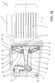
- the reference number 1 globally designates a self-priming centrifugal pump according to the present invention ( Figure 15).
- the pump 1, shown in Figure 15, comprises a pump body 2 set horizontally side by side with an electric motor 3 provided with its own connection box 4.
- a delivery chamber 5 Inside the pump body 2 are identified a delivery chamber 5, a pumping chamber 6 and an intake conduit 7.
- a motorised centrifugal impeller 8 (of a known type) rigidly connected to the shaft 9 of the electric motor 3.
- the intake conduit 7 extends between an intake hole 10, obtained in an upper part of the pump body 2, and the pumping chamber 6 into which it opens in alignment with the axis of the impeller 8.
- the intake conduit 7 has a branch 12 open towards the delivery chamber 5.
- the pumping chamber 6 is also peripherally in communication with the delivery chamber 5 through a diffuser 13 ( Figures 7-10).
- the intake conduit 7 and the delivery chamber 5 are positioned on the same side of the impeller 8 (but this solution is not mandatory), and the diffuser 13 is rigidly mounted between the inner wall of the pump body 2 and the outer wall of the intake conduit 7.
- the diffuser 13, which is positioned downstream of the impeller 8 with reference to the flow of the liquid in the pump 1, is constituted mainly by a first and by a second wall 14, 15, substantially shaped as annuli, which identify between them a diffusion chamber 16 having, at least mainly, continuous annular development.
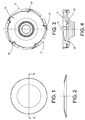
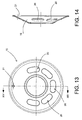
- the first wall 14 ( Figures 3-6) is oriented towards the impeller 8 whilst the second wall 15 ( Figures 11-14) faces the delivery chamber 5 of the pump 1.
- the communication between the pumping chamber 6 and the diffusion chamber 16 is assured by a plurality of openings 17 positioned along the outer circumferential periphery of the first wall 14, which allow the entry of the flow of liquid exiting the impeller 8 into the diffusion chamber 16.
- the diffusion 16 can be identified a first sector 18 and a second sector 19, one being a continuation of the other, in which the first sector 18 corresponds, in use, to the central upper portion of the ring defined by the diffusion chamber 16.
- the diffuser 13 has, viewed frontally, annulus shape, and the first sector 18 can be frontally identified as the upper sector of said circular crown ( Figures 7 and 9).
- the second wall 15 is substantially closed in correspondence with the first sector 18 of the diffusion chamber 16, whilst it has one or more through holes 20 in correspondence with the second sector 19. Said through holes 20 have the purpose of putting in communication the second sector 19 of the diffusion chamber 16 with the delivery chamber 5, thus allowing the passage of the liquid in substantially axial direction.
- the second wall 15 in correspondence with the first sector 18 of the diffusion chamber 16, can be either completely closed ( Figures 9-12), or it can have, in correspondence with the summit part of the first sector 18 of the diffusion chamber 16, a small vent hole 21 to allow the exit of any air present in the diffusion chamber 16 towards the delivery chamber 5 (figures 7, 8, 13, 14).
- the presence or absence of the vent hole 21 depends on the dimensioning of the diffuser 13. In particular when the extension of the first sector 18 is relatively high (Figure 13), the vent hole 21 is necessary to prevent air from accumulating in the upper part of the diffusion chamber 16. On the contrary, if the extension of the first sector 18 of the diffusion chamber 16 is relatively reduced ( Figure 11), the presence of the hole 21 is not indispensable since any air accumulated in the upper part of the diffusion chamber 16 would in any case be driven towards the delivery chamber 5 by the liquid in swirling motion which flows inside the diffuser 13.
- the through hole 20 (or the through holes 20 as the case may be) positioned in correspondence with the second sector 19 of the diffusion chamber 16 has elongated shape along the development of the second sector 19 itself, and covers most of the development thereof in order to maximise the flow of liquid from the diffusion chamber 16 to the delivery chamber 5.
- the illustrated embodiments comprise a plurality of through holes 20, distributed in succession along an arc of circumference having for its centre the axis of the impeller 8, but other embodiments may also comprise a single through hole 20 with equivalent size and shape.
- the diffuser 13 further comprises a plurality of spacers 22 interposed between the first and the second wall 14, 15, integral to the first wall 14 and positioned in correspondence with the external periphery of the diffusion chamber 16.
- said spacers 22 intercept the flow of the liquid entering tangentially into the diffusion chamber 16, they can be shaped slightly arched in order to facilitate the commencement in the diffusion chamber of a motion with rotational component about the axis of the impeller 8.
- the diffusion chamber 16 in addition to developing in annular fashion about the axis of rotation of the impeller 8, also has a development component parallel to said axis in the direction of the delivery chamber 5. In essence the chamber therefore develops mainly along the lateral surface of a cone frustum with its conicity oriented towards the delivery chamber 5.
- the pump body 2 in the illustrated embodiment it has, in addition to the intake hole 10, also a delivery hole 24 and a filling hole 25 obtained in the upper part, and a discharge hole 26 obtained in the lower part, all in communication with the delivery chamber 5.
- the pump 1 is mounted with the axis of the impeller 8 preferably in horizontal position, although slightly inclined positions are admissible provided they do not compromise the self-priming operation. Moreover, the first sector 18 of the diffusion chamber 16 is in the highest position.
- the liquid present inside the pump body 2 is made to flow cyclically between the delivery chamber 5, the intake conduit 7, the pumping chamber 6 and the diffusion chamber 16.
- the present invention thus achieves important advantages.
- the pump of the present invention assures a considerably shorter self-priming time than known pumps, thanks to its own ability to separate the air bubbles from the flow of liquid.
Landscapes
- Engineering & Computer Science (AREA)
- Mechanical Engineering (AREA)
- General Engineering & Computer Science (AREA)
- Structures Of Non-Positive Displacement Pumps (AREA)
Claims (9)
- Selbstansaugende Kreiselpumpe, enthaltend- einen Pumpenkörper (2);- ein angetriebenes Laufrad (8), montiert im Inneren des Körpers (2); und- einen Diffusor (13), unter Bezugnahme auf die Fliessrichtung einer Flüssigkeit in der Pumpe (1) stromabwärts des Laufrades (8) positioniert und eine erste und eine zweite Wand (14), (15) aufweisend, die zwischen sich eine Diffusionskammer (16) bilden, die wenigstens vorwiegend einen kontinuierlichen ringförmigen Verlauf hat, wobei die genannte erste Wand (14) zu dem genannten Laufrad (8) hin orientiert ist und die genannte zweite Wand (15) zu der Förderkammer (5) der Pumpe (1), wobei die genannte erste Wand (14) eine Anzahl von Öffnungen (17) aufweist, positioniert entlang ihrem äusseren Umlauf, um den Eintritt des Flusses der aus dem Laufrad (8) austretenden Flüssigkeit in die Diffusionskammer (16) zu erlauben, und wobei die genannte zweite Wand (15) wenigstens eine durchgehende Bohrung (20) aufweist, um die Diffusionskammer (16) mit der Förderkammer (5) in Verbindung zu bringen;
dadurch gekennzeichnet, dass die genannte ringförmige Diffusionskammer (16) einen ersten Sektor (18) und einen zweiten Sektor (19) hat, wobei einer die Weiterführung des anderen ist, wobei der genannte erste Sektor (18) im Betrieb einem oberen Abschnitt der genannten Diffusionskammer (16) entspricht, und dadurch, dass die genannte zweite Wand (15) entsprechend dem genannten ersten Sektor (18) im wesentlichen geschlossen ist, wobei die genannte durchgehende Bohrung (20) entsprechend zu dem zweiten Sektor (19) erhalten ist, um den genannten zweiten Sektor (19) der Diffusionskammer (16) mit der Förderkammer (5) in Verbindung zu bringen. - Selbstansaugende Kreiselpumpe nach Patentanspruch 1, dadurch gekennzeichnet, dass die genannte durchgehende Bohrung (20) eine verlängerte Form entlang dem Verlauf des zweiten Sektors (19) der Diffusionskammer (16) aufweist.
- Selbstansaugende Kreiselpumpe nach Patentanspruch 1 oder 2, dadurch gekennzeichnet, dass sie eine einzige durchgehende Bohrung (20) hat, die sich entlang dem grössten Teil des Verlaufs des zweiten Sektors (19) der Diffusionskammer (16) erstreckt.
- Selbstansaugende Kreiselpumpe nach Patentanspruch 1 oder 2, dadurch gekennzeichnet, dass die genannte zweite Wand (15) eine Anzahl von durchgehenden Bohrungen (20) aufweist, die entlang dem Verlauf des zweiten Sektors (19) der Diffusionskammer (16) verteilt sind.
- Selbstansaugende Kreiselpumpe nach Patentanspruch 4, dadurch gekennzeichnet, dass die genannte Anzahl von Bohrungen entlang dem Kreisbogen verteilt ist.
- Selbstansaugende Kreiselpumpe nach Patentanspruch 1, dadurch gekennzeichnet, dass der genannte Diffusor (13) ausserdem eine Anzahl von Abstandsstücken (22) enthält, eingesetzt zwischen der ersten und der zweiten Wand (14), (15) und positioniert entsprechend zu dem äusseren Umlauf der Diffusionskammer (16).
- Selbstansaugende Kreiselpumpe nach einem beliebigen der vorstehenden Patentansprüche, dadurch gekennzeichnet, dass die genannte Diffusionskammer (16) vorwiegend entlang der seitlichen Oberfläche eines Stumpfkegels verläuft, mit der Konizität zu der Förderkammer (5) hin gerichtet.
- Selbstansaugende Kreiselpumpe nach einem beliebigen der vorstehenden Patentansprüche, dadurch gekennzeichnet, dass der genannte erste Sektor (18) der Diffusionskammer (16) im Betrieb einem mittleren oberen Abschnitt der genannten Diffusionskammer (16), entspricht.
- Selbstansaugende Kreiselpumpe nach einem beliebigen der vorstehenden Patentansprüche, dadurch gekennzeichnet, dass die genannte zweite Wand (15) entsprechend zu dem obersten Teil des ersten Sektors (18) der Diffusionskammer (16) eine kleine Entlüftungsbohrung (21) hat, um das Entweichen eventueller, in der Diffusionskammer (16) vorhandener Luft zu der Förderkammer (5) hin zu erlauben.
Priority Applications (4)
| Application Number | Priority Date | Filing Date | Title |
|---|---|---|---|
| DE60303788T DE60303788T2 (de) | 2003-08-29 | 2003-08-29 | Selbstansaugende Kreiselpumpe |
| AT03425564T ATE319012T1 (de) | 2003-08-29 | 2003-08-29 | Selbstansaugende kreiselpumpe |
| ES03425564T ES2258712T3 (es) | 2003-08-29 | 2003-08-29 | Bomba centrifuga autocebante. |
| EP03425564A EP1510696B1 (de) | 2003-08-29 | 2003-08-29 | Selbstansaugende Kreiselpumpe |
Applications Claiming Priority (1)
| Application Number | Priority Date | Filing Date | Title |
|---|---|---|---|
| EP03425564A EP1510696B1 (de) | 2003-08-29 | 2003-08-29 | Selbstansaugende Kreiselpumpe |
Publications (2)
| Publication Number | Publication Date |
|---|---|
| EP1510696A1 EP1510696A1 (de) | 2005-03-02 |
| EP1510696B1 true EP1510696B1 (de) | 2006-03-01 |
Family
ID=34089797
Family Applications (1)
| Application Number | Title | Priority Date | Filing Date |
|---|---|---|---|
| EP03425564A Expired - Lifetime EP1510696B1 (de) | 2003-08-29 | 2003-08-29 | Selbstansaugende Kreiselpumpe |
Country Status (4)
| Country | Link |
|---|---|
| EP (1) | EP1510696B1 (de) |
| AT (1) | ATE319012T1 (de) |
| DE (1) | DE60303788T2 (de) |
| ES (1) | ES2258712T3 (de) |
Families Citing this family (4)
| Publication number | Priority date | Publication date | Assignee | Title |
|---|---|---|---|---|
| CN103148017B (zh) * | 2013-04-02 | 2016-05-04 | 陈坚 | 自吸喷射泵导流罩的防空气倒流的挡板 |
| FR3020386B1 (fr) * | 2014-04-25 | 2017-08-18 | Victor Jean Ballestra | Dispositif d'evacuation sanitaire pour l'evacuation des eaux d'une douche |
| JP6010588B2 (ja) * | 2014-07-29 | 2016-10-19 | 本田技研工業株式会社 | 遠心ポンプ |
| CN106224249B (zh) * | 2016-09-09 | 2017-11-03 | 浙江新控泵业有限公司 | 低噪音自吸复合泵 |
Family Cites Families (4)
| Publication number | Priority date | Publication date | Assignee | Title |
|---|---|---|---|---|
| US2941474A (en) * | 1956-08-20 | 1960-06-21 | Fairbanks Morse & Co | Self-priming pumping apparatus |
| US2934021A (en) * | 1956-10-09 | 1960-04-26 | F E Meyers & Bro Co | Shallow well self-priming jet pump |
| DE3718273C2 (de) * | 1986-09-01 | 1994-12-15 | Apollowerk Goesnitz Gmbh | Selbstansaugende horizontale Radialkreiselpumpe |
| IT1225597B (it) * | 1988-09-26 | 1990-11-22 | Calpeda A Spa | Pompa autoadescante ad eiettore con corona direttrice assiale. |
-
2003
- 2003-08-29 ES ES03425564T patent/ES2258712T3/es not_active Expired - Lifetime
- 2003-08-29 EP EP03425564A patent/EP1510696B1/de not_active Expired - Lifetime
- 2003-08-29 AT AT03425564T patent/ATE319012T1/de not_active IP Right Cessation
- 2003-08-29 DE DE60303788T patent/DE60303788T2/de not_active Expired - Lifetime
Also Published As
| Publication number | Publication date |
|---|---|
| DE60303788T2 (de) | 2006-10-05 |
| ATE319012T1 (de) | 2006-03-15 |
| ES2258712T3 (es) | 2006-09-01 |
| EP1510696A1 (de) | 2005-03-02 |
| DE60303788D1 (de) | 2006-04-27 |
Similar Documents
| Publication | Publication Date | Title |
|---|---|---|
| US10495102B2 (en) | Impeller and pump using the impeller | |
| EP0401670B1 (de) | Selbstansaugende Kreiselpumpe | |
| US6030180A (en) | Apparatus for generating water currents in swimming pools or the like | |
| CN107202019B (zh) | 一种多功能水泵 | |
| ES2579005T3 (es) | Bomba centrífuga | |
| US6152688A (en) | Fuel pump | |
| US7059824B2 (en) | Self priming centrifugal pump | |
| EP0552661B1 (de) | Selbstansaugende Kreiselpumpe | |
| KR20020084222A (ko) | 촉진된 자동-프라이밍을 가진 원심 펌프 | |
| EP0732504A1 (de) | Selbstansaugende kreiselpumpe | |
| EP1510696A1 (de) | Selbstansaugende Kreiselpumpe | |
| KR101647421B1 (ko) | 다단식 원심펌프 | |
| US4627792A (en) | Rotating flow pump with a feed pump unit formed as an ejector | |
| KR101776883B1 (ko) | 압력발생날개가 부가된 임펠러를 포함하는 원심펌프 | |
| US5007798A (en) | Centrifugal pump | |
| IT9085579A1 (it) | Diffusore longitudinale periferico per pompa monogirante centrifuga autoadescante | |
| US20250122883A1 (en) | Flow pump | |
| CN209925228U (zh) | 卧式排污泵 | |
| SE443407B (sv) | Inloppskrok for centrifugalpumpar | |
| US4401409A (en) | Self-priming centrifugal pump | |
| CN216407194U (zh) | 一种泵腔结构及立式泵 | |
| CN222526554U (zh) | 离心式泵 | |
| JP7398405B2 (ja) | 立軸ポンプ | |
| JP2004027877A (ja) | 立軸斜流ポンプ | |
| US2808784A (en) | Submerged booster pump |
Legal Events
| Date | Code | Title | Description |
|---|---|---|---|
| PUAI | Public reference made under article 153(3) epc to a published international application that has entered the european phase |
Free format text: ORIGINAL CODE: 0009012 |
|
| 17P | Request for examination filed |
Effective date: 20040707 |
|
| AK | Designated contracting states |
Kind code of ref document: A1 Designated state(s): AT BE BG CH CY CZ DE DK EE ES FI FR GB GR HU IE IT LI LU MC NL PT RO SE SI SK TR |
|
| AX | Request for extension of the european patent |
Extension state: AL LT LV MK |
|
| GRAP | Despatch of communication of intention to grant a patent |
Free format text: ORIGINAL CODE: EPIDOSNIGR1 |
|
| GRAS | Grant fee paid |
Free format text: ORIGINAL CODE: EPIDOSNIGR3 |
|
| AKX | Designation fees paid |
Designated state(s): AT BE BG CH CY CZ DE DK EE ES FI FR GB GR HU IE IT LI LU MC NL PT RO SE SI SK TR |
|
| GRAA | (expected) grant |
Free format text: ORIGINAL CODE: 0009210 |
|
| AK | Designated contracting states |
Kind code of ref document: B1 Designated state(s): AT BE BG CH CY CZ DE DK EE ES FI FR GB GR HU IE IT LI LU MC NL PT RO SE SI SK TR |
|
| PG25 | Lapsed in a contracting state [announced via postgrant information from national office to epo] |
Ref country code: SI Free format text: LAPSE BECAUSE OF FAILURE TO SUBMIT A TRANSLATION OF THE DESCRIPTION OR TO PAY THE FEE WITHIN THE PRESCRIBED TIME-LIMIT Effective date: 20060301 Ref country code: RO Free format text: LAPSE BECAUSE OF FAILURE TO SUBMIT A TRANSLATION OF THE DESCRIPTION OR TO PAY THE FEE WITHIN THE PRESCRIBED TIME-LIMIT Effective date: 20060301 Ref country code: FI Free format text: LAPSE BECAUSE OF FAILURE TO SUBMIT A TRANSLATION OF THE DESCRIPTION OR TO PAY THE FEE WITHIN THE PRESCRIBED TIME-LIMIT Effective date: 20060301 Ref country code: CH Free format text: LAPSE BECAUSE OF FAILURE TO SUBMIT A TRANSLATION OF THE DESCRIPTION OR TO PAY THE FEE WITHIN THE PRESCRIBED TIME-LIMIT Effective date: 20060301 Ref country code: NL Free format text: LAPSE BECAUSE OF FAILURE TO SUBMIT A TRANSLATION OF THE DESCRIPTION OR TO PAY THE FEE WITHIN THE PRESCRIBED TIME-LIMIT Effective date: 20060301 Ref country code: BE Free format text: LAPSE BECAUSE OF FAILURE TO SUBMIT A TRANSLATION OF THE DESCRIPTION OR TO PAY THE FEE WITHIN THE PRESCRIBED TIME-LIMIT Effective date: 20060301 Ref country code: SK Free format text: LAPSE BECAUSE OF FAILURE TO SUBMIT A TRANSLATION OF THE DESCRIPTION OR TO PAY THE FEE WITHIN THE PRESCRIBED TIME-LIMIT Effective date: 20060301 Ref country code: AT Free format text: LAPSE BECAUSE OF FAILURE TO SUBMIT A TRANSLATION OF THE DESCRIPTION OR TO PAY THE FEE WITHIN THE PRESCRIBED TIME-LIMIT Effective date: 20060301 Ref country code: LI Free format text: LAPSE BECAUSE OF FAILURE TO SUBMIT A TRANSLATION OF THE DESCRIPTION OR TO PAY THE FEE WITHIN THE PRESCRIBED TIME-LIMIT Effective date: 20060301 |
|
| REG | Reference to a national code |
Ref country code: GB Ref legal event code: FG4D |
|
| REG | Reference to a national code |
Ref country code: CH Ref legal event code: EP |
|
| REG | Reference to a national code |
Ref country code: IE Ref legal event code: FG4D |
|
| REF | Corresponds to: |
Ref document number: 60303788 Country of ref document: DE Date of ref document: 20060427 Kind code of ref document: P |
|
| PG25 | Lapsed in a contracting state [announced via postgrant information from national office to epo] |
Ref country code: DK Free format text: LAPSE BECAUSE OF FAILURE TO SUBMIT A TRANSLATION OF THE DESCRIPTION OR TO PAY THE FEE WITHIN THE PRESCRIBED TIME-LIMIT Effective date: 20060601 Ref country code: BG Free format text: LAPSE BECAUSE OF FAILURE TO SUBMIT A TRANSLATION OF THE DESCRIPTION OR TO PAY THE FEE WITHIN THE PRESCRIBED TIME-LIMIT Effective date: 20060601 Ref country code: SE Free format text: LAPSE BECAUSE OF FAILURE TO SUBMIT A TRANSLATION OF THE DESCRIPTION OR TO PAY THE FEE WITHIN THE PRESCRIBED TIME-LIMIT Effective date: 20060601 |
|
| REG | Reference to a national code |
Ref country code: GR Ref legal event code: EP Ref document number: 20060401798 Country of ref document: GR |
|
| REG | Reference to a national code |
Ref country code: HU Ref legal event code: AG4A Ref document number: E000415 Country of ref document: HU |
|
| PG25 | Lapsed in a contracting state [announced via postgrant information from national office to epo] |
Ref country code: PT Free format text: LAPSE BECAUSE OF FAILURE TO SUBMIT A TRANSLATION OF THE DESCRIPTION OR TO PAY THE FEE WITHIN THE PRESCRIBED TIME-LIMIT Effective date: 20060801 |
|
| PG25 | Lapsed in a contracting state [announced via postgrant information from national office to epo] |
Ref country code: IE Free format text: LAPSE BECAUSE OF NON-PAYMENT OF DUE FEES Effective date: 20060829 |
|
| PG25 | Lapsed in a contracting state [announced via postgrant information from national office to epo] |
Ref country code: MC Free format text: LAPSE BECAUSE OF NON-PAYMENT OF DUE FEES Effective date: 20060831 |
|
| NLV1 | Nl: lapsed or annulled due to failure to fulfill the requirements of art. 29p and 29m of the patents act | ||
| REG | Reference to a national code |
Ref country code: ES Ref legal event code: FG2A Ref document number: 2258712 Country of ref document: ES Kind code of ref document: T3 |
|
| REG | Reference to a national code |
Ref country code: CH Ref legal event code: PL |
|
| PLBI | Opposition filed |
Free format text: ORIGINAL CODE: 0009260 |
|
| PLAX | Notice of opposition and request to file observation + time limit sent |
Free format text: ORIGINAL CODE: EPIDOSNOBS2 |
|
| 26 | Opposition filed |
Opponent name: CALPEDA S.P.A. Effective date: 20061201 |
|
| EN | Fr: translation not filed | ||
| PLBB | Reply of patent proprietor to notice(s) of opposition received |
Free format text: ORIGINAL CODE: EPIDOSNOBS3 |
|
| GBPC | Gb: european patent ceased through non-payment of renewal fee |
Effective date: 20070829 |
|
| PG25 | Lapsed in a contracting state [announced via postgrant information from national office to epo] |
Ref country code: CZ Free format text: LAPSE BECAUSE OF FAILURE TO SUBMIT A TRANSLATION OF THE DESCRIPTION OR TO PAY THE FEE WITHIN THE PRESCRIBED TIME-LIMIT Effective date: 20060301 Ref country code: FR Free format text: LAPSE BECAUSE OF FAILURE TO SUBMIT A TRANSLATION OF THE DESCRIPTION OR TO PAY THE FEE WITHIN THE PRESCRIBED TIME-LIMIT Effective date: 20070309 |
|
| PGFP | Annual fee paid to national office [announced via postgrant information from national office to epo] |
Ref country code: GR Payment date: 20070727 Year of fee payment: 5 |
|
| PG25 | Lapsed in a contracting state [announced via postgrant information from national office to epo] |
Ref country code: EE Free format text: LAPSE BECAUSE OF FAILURE TO SUBMIT A TRANSLATION OF THE DESCRIPTION OR TO PAY THE FEE WITHIN THE PRESCRIBED TIME-LIMIT Effective date: 20060301 |
|
| PG25 | Lapsed in a contracting state [announced via postgrant information from national office to epo] |
Ref country code: LU Free format text: LAPSE BECAUSE OF NON-PAYMENT OF DUE FEES Effective date: 20060829 |
|
| PG25 | Lapsed in a contracting state [announced via postgrant information from national office to epo] |
Ref country code: FR Free format text: LAPSE BECAUSE OF FAILURE TO SUBMIT A TRANSLATION OF THE DESCRIPTION OR TO PAY THE FEE WITHIN THE PRESCRIBED TIME-LIMIT Effective date: 20060301 Ref country code: CY Free format text: LAPSE BECAUSE OF FAILURE TO SUBMIT A TRANSLATION OF THE DESCRIPTION OR TO PAY THE FEE WITHIN THE PRESCRIBED TIME-LIMIT Effective date: 20060301 Ref country code: GB Free format text: LAPSE BECAUSE OF NON-PAYMENT OF DUE FEES Effective date: 20070829 |
|
| PG25 | Lapsed in a contracting state [announced via postgrant information from national office to epo] |
Ref country code: GR Free format text: LAPSE BECAUSE OF NON-PAYMENT OF DUE FEES Effective date: 20090304 |
|
| PLAB | Opposition data, opponent's data or that of the opponent's representative modified |
Free format text: ORIGINAL CODE: 0009299OPPO |
|
| PGFP | Annual fee paid to national office [announced via postgrant information from national office to epo] |
Ref country code: TR Payment date: 20110801 Year of fee payment: 9 Ref country code: ES Payment date: 20110824 Year of fee payment: 9 Ref country code: DE Payment date: 20110802 Year of fee payment: 9 |
|
| PGFP | Annual fee paid to national office [announced via postgrant information from national office to epo] |
Ref country code: HU Payment date: 20111123 Year of fee payment: 9 |
|
| PLBP | Opposition withdrawn |
Free format text: ORIGINAL CODE: 0009264 |
|
| PLBD | Termination of opposition procedure: decision despatched |
Free format text: ORIGINAL CODE: EPIDOSNOPC1 |
|
| PLBM | Termination of opposition procedure: date of legal effect published |
Free format text: ORIGINAL CODE: 0009276 |
|
| STAA | Information on the status of an ep patent application or granted ep patent |
Free format text: STATUS: OPPOSITION PROCEDURE CLOSED |
|
| 27C | Opposition proceedings terminated |
Effective date: 20120618 |
|
| PG25 | Lapsed in a contracting state [announced via postgrant information from national office to epo] |
Ref country code: HU Free format text: LAPSE BECAUSE OF NON-PAYMENT OF DUE FEES Effective date: 20120830 |
|
| PG25 | Lapsed in a contracting state [announced via postgrant information from national office to epo] |
Ref country code: DE Free format text: LAPSE BECAUSE OF NON-PAYMENT OF DUE FEES Effective date: 20130301 |
|
| REG | Reference to a national code |
Ref country code: DE Ref legal event code: R119 Ref document number: 60303788 Country of ref document: DE Effective date: 20130301 |
|
| REG | Reference to a national code |
Ref country code: ES Ref legal event code: FD2A Effective date: 20131021 |
|
| PG25 | Lapsed in a contracting state [announced via postgrant information from national office to epo] |
Ref country code: ES Free format text: LAPSE BECAUSE OF NON-PAYMENT OF DUE FEES Effective date: 20120830 |
|
| PG25 | Lapsed in a contracting state [announced via postgrant information from national office to epo] |
Ref country code: TR Free format text: LAPSE BECAUSE OF NON-PAYMENT OF DUE FEES Effective date: 20120829 |
|
| PGFP | Annual fee paid to national office [announced via postgrant information from national office to epo] |
Ref country code: IT Payment date: 20220831 Year of fee payment: 20 |
|
| P01 | Opt-out of the competence of the unified patent court (upc) registered |
Effective date: 20230412 |