EP1510419A1 - Aufblasvorrichtung - Google Patents
Aufblasvorrichtung Download PDFInfo
- Publication number
- EP1510419A1 EP1510419A1 EP03736042A EP03736042A EP1510419A1 EP 1510419 A1 EP1510419 A1 EP 1510419A1 EP 03736042 A EP03736042 A EP 03736042A EP 03736042 A EP03736042 A EP 03736042A EP 1510419 A1 EP1510419 A1 EP 1510419A1
- Authority
- EP
- European Patent Office
- Prior art keywords
- filter
- inflator
- gas
- pressurized gas
- rupturable plate
- Prior art date
- Legal status (The legal status is an assumption and is not a legal conclusion. Google has not performed a legal analysis and makes no representation as to the accuracy of the status listed.)
- Withdrawn
Links
Images


Classifications
-
- B—PERFORMING OPERATIONS; TRANSPORTING
- B60—VEHICLES IN GENERAL
- B60R—VEHICLES, VEHICLE FITTINGS, OR VEHICLE PARTS, NOT OTHERWISE PROVIDED FOR
- B60R21/00—Arrangements or fittings on vehicles for protecting or preventing injuries to occupants or pedestrians in case of accidents or other traffic risks
- B60R21/02—Occupant safety arrangements or fittings, e.g. crash pads
- B60R21/16—Inflatable occupant restraints or confinements designed to inflate upon impact or impending impact, e.g. air bags
- B60R21/26—Inflatable occupant restraints or confinements designed to inflate upon impact or impending impact, e.g. air bags characterised by the inflation fluid source or means to control inflation fluid flow
- B60R21/261—Inflatable occupant restraints or confinements designed to inflate upon impact or impending impact, e.g. air bags characterised by the inflation fluid source or means to control inflation fluid flow with means other than bag structure to diffuse or guide inflation fluid
-
- B—PERFORMING OPERATIONS; TRANSPORTING
- B60—VEHICLES IN GENERAL
- B60R—VEHICLES, VEHICLE FITTINGS, OR VEHICLE PARTS, NOT OTHERWISE PROVIDED FOR
- B60R21/00—Arrangements or fittings on vehicles for protecting or preventing injuries to occupants or pedestrians in case of accidents or other traffic risks
- B60R21/02—Occupant safety arrangements or fittings, e.g. crash pads
- B60R21/16—Inflatable occupant restraints or confinements designed to inflate upon impact or impending impact, e.g. air bags
- B60R21/26—Inflatable occupant restraints or confinements designed to inflate upon impact or impending impact, e.g. air bags characterised by the inflation fluid source or means to control inflation fluid flow
Definitions
- the present invention relates to an inflator in which a flow amount of a pressurized gas can be kept stable at a time of activation, and a filter for an inflator suitable for the inflator.
- a filter 20 is disposed in front of a gas discharging port 18 to prevent fragments of a first rupturable plate 22 or the like from entering an air bag.
- a wire mesh or a porous flat plate is used as the filter 20.
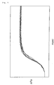
- Fig. 6 shows pressure changes in a tank in a 60-liter tank test, in which there is variations in pressure change with time.
- the details of a test method shown in Fig. 6 are similar to examples.
- JP-B No. 3001985 and JP-A 2000-508985 are known.
- an opening portion of a container including a pressurized medium 50 is closed by a burst disc 48, and a filter 108 is disposed in front of the burst disc.
- the filter 108 prevents fragments of the burst disc 108 from entering a valve assembly 40.
- a top member 30 formed with an outlet 40 is attached to an end portion of a pressure container 22 containing a pressurized medium and a disk 34 is further arranged.
- a perforated screen, a filter or a trap 42 is disposed between the outlet 40 and the disk 34. The screen 42 arrests particles contained in a discharged gas flow.
- An object of the present invention is to provide an inflator which can easily keep a flow amount of a pressurized gas constant at activation of the inflator, and a filter for an inflator suitable for the inflator.
- an inflator comprising an inflator housing which has an opening portion and is charged with a pressurized gas, a diffuser portion which is provided in the opening portion side of the inflator housing and has a gas discharging port for discharging outside a pressurized gas flowing from the opening portion at activation, and a first rupturable plate closing a pressurized gas flow path between the diffuser portion and the gas discharging port, wherein a filter is disposed between the first rupturable plate and the gas discharging port, the filter comprises a flat plate with many holes except for a wire mesh, and a surface of the filter in the first rupturable plate side has a concave portion and a convex portion.
- the filter by forming the filter to have a porous flat shape having a concave portion and a convex portion on the surface, even if plural fragments are produced and attached to the surface of the filter when the rupturable plate is ruptured, the filter surface is not covered with fragments and a flow path for the pressurized gas is always secured, because the filter surface is provided with the concave portion and the convex portion. Accordingly, a flow amount of the pressurized gas is kept constant.
- the above-described invention can employ such a constitution that a convex portion of the filter is formed continuously and a concave portion thereof forms a groove, or such a constitution that a convex portion of the filter is formed continuously and a concave portion thereof forms a single or double or more concentric grooves, or alternatively such a constitution that a convex portion of the filter includes plural independent projections.
- a flow amount of the pressurized gas is adjusted by the many holes formed in the filter.
- an inflator comprising an inflator housing which has an opening portion and is charged with a pressurized gas, a diffuser portion which is provided in the opening portion side of the inflator housing and has a gas discharging port for discharging outside a pressurized gas flowing from the opening portion at activation, and a first rupturable plate closing a pressurized gas flow path between the diffuser portion and the gas discharging port, wherein a screen is disposed between the first rupturable plate and the gas discharging port, a filter is disposed to contact the screen, the filter is porous and have a sectional configuration of an arc shape, and the filter is disposed such that an opening portion thereof is directed to the first rupturable plate side and a spherical surface thereof contacts with the screen.
- a filter having a sectional configuration of an arc shape that is, a filter having a shape like a cut hollow sphere, preferably, a semi-spherical shape or a shape similar thereto
- a filter having a sectional configuration of an arc shape that is, a filter having a shape like a cut hollow sphere, preferably, a semi-spherical shape or a shape similar thereto
- the filter acts in a manner similar to the filter of the invention described in claim 1.
- the filter since the filter is disposed such that its opening is directed to the first rupturable plate side and the spherical surface contacts with the screen, fragments tend to be stored in a bottom (a bottom of a sphere) of an inner surface of the filter.
- the holes on the peripheral surface of the filter are kept ventilated, the above action can be suitably obtained.
- an inflator comprising an inflator housing which has an opening portion and is charged with a pressurized gas, a diffuser portion which is provided in the opening portion side of the inflator housing and has a gas discharging port for discharging outside a pressurized gas flowing from the opening portion at activation, and a first rupturable plate closing a pressurized gas flow path between the diffuser portion and the gas discharging port, wherein a screen is disposed between the first rupturable plate and the gas discharging port, a filter is disposed to contact the screen, the filter is porous and have a sectional configuration of an arc shape, and the filter is disposed in a state that a spherical surface thereof is directed to the first rupturable plate side and a peripheral edge of an opening portion thereof contacts with the screen.
- a filter having a sectional configuration of an arc shape that is, a filter having a shape like a cut hollow sphere, preferably, a semi-spherical shape or a shape similar thereto
- the filter acts in a manner similar to the filter of the invention described in claim 1.
- the filter since the filter is disposed such that its spherical surface is directed to the first rupturable plate side and the peripheral edge of an opening portion thereof contacts with the screen, fragments tend to be stored not in the top of the sphere but in the vicinity of a portion between the filter peripheral surface and an inner wall surface of the diffuser portion.
- the holes on the peripheral surface of the filter are kept ventilated, the above action can be suitably obtained.
- plural independent projections, or one or two or more grooves can be formed on a surface of the filter having a semi-spherical shape or the like in the first rupturable plate side, and the grooves can be formed concentrically.
- the filter has an extension portion which is extended from a peripheral edge of the opening portion of the semi-spherical filter and the extension portion can be formed such that the more it is extended from the peripheral edge of the opening portion, the smaller an outer diameter of the extension portion becomes than the peripheral edge of the opening portion. Since the outer diameter of the filter having a semi-spherical shape or the like is substantially the same as the inner diameter of the diffuser portion, particularly, when the filter having a semi-spherical shape or the like is fitted into the diffuser portion from the opening portion, it is difficult to fit the same as it is.
- the outer diameter of the extension portion provided at the peripheral edge of the opening portion of the filter is made smaller as it extends from the peripheral edge of the opening portion of the filter, the diffuser portion is fitted easily. In this case, it is unnecessary to provide holes in the extension portion of the filter.
- such a constitution can be employed that a combustion chamber accommodating a solid gas generating agent which generates a combustion gas is provided in the inflator housing is provided and a second rupturable plate closes between the combustion chamber and a space in which the pressurized gas is charged, and such a constitution can further be employed that the combustion chamber is provided at an end portion of the inflator housing and an igniter is arranged in the combustion chamber.
- the invention described in claim 13 provides, as another means for solving the above problem, a filter for an inflator used in an inflator for using a pressurized gas to inflate a body to be inflated and preventing foreign matters from entering the body to be inflated, wherein the filter comprises a porous flat plate except for a wire mesh, and a surface of the filter facing a pressurized gas flow has a concave portion and a convex portion.
- the concave portion and the convex portion may be formed in a groove(s) or an independent projection(s).
- Such a filter can prevent foreign matters, such as fragments produced by rupture of the rupturable plate, from entering the body to be inflated such as an air bag or the like, and it functions to keep a flow amount of the pressurized gas stable as in the case of each of the above-described inventions when the inflator is used.
- the invention described in claim 14 provides, as another means for solving the above-described problem, an inflator comprising an inflator housing which has an opening portion and is charged with a pressurized gas, a diffuser portion which is provided in the opening portion side of the inflator housing and has a gas discharging port for discharging outside a pressurized gas flowing from the opening portion at activation, and a first rupturable plate closing a pressurized gas flow path between the diffuser portion and the gas discharging port, wherein a filter is provided in a gas flow path inside the diffuser portion, the filter is formed in a cap-like shape having one end portion closed and the other end portion opened, plural communication holes are formed in a side wall portion of the filter apart from the opened end portion of the filter, and the filter is disposed such that the closed end portion of the filter is directed to the first rupturable plate and the end portion of the filter on the opened side contacts with a wall portion provided with the gas discharging port.
- the filter in a cap-like shape to have plural communication holes at its portion far from the opened end portion and disposing the filter such that the opened end portion thereof contacts with the wall portion provided with the gas discharging port, a pocket portion is formed between the side wall surface of the filter and an inner wall surface of the gas passage. Since the pocket portion exists in a direction of flow of a gas discharged from the opening portion of the inflator housing, fragments of the rupturable plate included in the gas discharged are stored in the pocket portion. Thereby, the fragments of the rupturable plate are arrested in the pocket portion and the fragments is not discharged outside the inflator.
- the plural communication holes are formed in the side wall surface of the filter and the gas discharged from the opening portion of the inflator housing reaches the gas discharging port through the communication holes, and thereby, the degree of detour of a gas is increased and more (or smaller) fragments of the rupturable plate can be arrested in the pocket portion.
- the filter has a principal function for forming a pocket portion between the side wall portion and an inner wall surface defining a gas flow path in the diffuser portion. That is, the side wall portion of the filter is provided with the plural communication holes at a certain distance from the opened end portion, but the depth of the pocket portion corresponds to that certain distance. Therefore, the depth of the pocket portion can be adjusted by adjusting the position of the communication holes. Since a pressurized gas or a combustion gas (a gas generated by combustion of the solid gas generating agent) once flows along the depth direction of the pocket portion, fragments of the rupturable plate or combustion residue included the gases is easily stored in the pocket portion.
- a pressurized gas or a combustion gas a gas generated by combustion of the solid gas generating agent
- the filter in the inflator in which the pocket portion is formed by the filter, a flow direction of a gas is changed by the filter and fragments of the rupturable plate or the like included in a gas can be stored in the pocket portion, the filter surface is not covered with the fragments and the flow path for the pressurized gas is always secured, because the pocket portion collects fragments of the rupturable plate or the like, so that the an inflator in which a flow amount is kept constant is realized.
- the filter may have a filtering function if opening areas of the plural communication holes formed in the filter are large enough not to disturb passing-through of the pressurized gas in the housing and the combustion gas.
- the entire shape may be made cylindrical, or alternatively, its outer configuration may be formed in various prisms such as a square prism.
- the filter can be also formed with an expanded portion obtained by further expanding the side wall portion in the opened side.
- the expanded portion may be formed, for example, in an outward flange shape or it may be formed in a skirt shape expanded gradually outwardly toward the opening end portion of the filter.
- the filter can be prevented from moving in a flow direction of a gas with receiving a pressure of the gas. For example, when a distal end of the expanded portion abuts on an inner wall surface (a wall defining the gas flow path) of the diffuser portion and is fitted into the inner wall, the filter can securely be blocked from moving due to the flow of a gas.
- the pocket portion can be formed deeper, and even more fragments and smaller fragments can be captured. Therefore, it is preferable that the expanded portion is formed to gradually expand in a skirt shape.
- an inflator comprising an inflator housing which has an opening portion and is charged with a pressurized gas, a diffuser portion which is provided in the opening portion side of the inflator housing and has a gas discharging port for discharging outside a pressurized gas flowing from the opening portion at activation, and a first rupturable plate closing a pressurized gas flow path between the diffuser portion and the gas discharging port, wherein a filter is provided in a gas flow path inside the diffuser portion, the filter is formed in a cap-like shape having one end portion closed and the other end portion opened, plural communication holes are formed in a side wall portion of the filter apart from the closed end portion of the filter, and an expanded portion is formed by further expanding the opened side of the filter outwardly and the filter is arranged such that the opened end portion is directed to the first rupturable plate and the expanded portion is fitted to a step portion provided in the diffuser portion.
- the filter is formed into a cap-like shape to have plural communication holes at a portion apart from the closed end portion, is provided with the expanded portion in the opened side, and has the expanded portion fitted into the step portion provided in the diffuser portion in such a state that the end portion of the filter on the opened side is directed to the first rupturable plate, and consequently, the pocket portion is formed at the closed end portion in the filter.
- the pocket portion exists in a flow direction of a gas discharged from the opening portion of the inflator housing, fragments of the rupturable plate included in a discharged gas or combustion residues generated by combustion of the solid gas generating agent are stored in the pocket portion. Thereby, the fragments of the rupturable plate are collected at the pocket portion and the fragments of the rupturable plate are not discharged outside the inflator.
- the filter has a principal function for forming the pocket portion. That is, the side wall portion of the filter is provided with the plural communication holes at a certain distance from the closed end portion, but the depth of the pocket portion corresponds to that certain distance. Therefore, the depth of the pocket portion can be adjusted by adjusting the position of the communication holes.
- a pressurized gas or a combustion gas once flows along the depth direction of the pocket portion and then changes its direction largely, so that at this time, fragments of the rupturable plate or combustion residues are left in the pocket portion
- the filter may have a filtering function.
- the entire shape may be made cylindrical, or alternatively, its outer configuration may be formed in various prisms such as a square prism.
- the expanded portion is formed into a outward flange-like shape.
- a continuous projection can be formed on a wall surface having the gas discharging port inside the diffuser portion.
- grooves appearing between the projection and an inner surface of the side wall portion or between the projections also serve as a pocket portion for storing fragments of the rupturable plate, thereby securely arresting fragments of the rupturable plate.
- a projection formed inside the wall surface having the gas discharging port namely, inside the diffuser portion
- the groove exists in the course of a gas which has changes the flow direction after being discharged radially from the communication holes of the filter and striking against an inner surface of the side wall of the diffuser portion.
- the groove exists in a direction in which a gas directly flows after it strikes against the inner surface of the side wall in the diffuser portion and changes its flow direction.
- the filter By press-fitting the expanded portion into the step portion provided inside the diffuser portion or welding the former to the latter, the filter can be fixed easily.
- a resistance-welding is particularly preferable in view of easiness in performing a welding.
- the pocket portion or the groove in the present invention collects not only fragments of the rupturable plate but also combustion residues generated by combustion of a solid gas generating agent when the solid gas generating agent is contained in the inflator.
- the inflator of the present invention since the flow amount of the pressurized gas can be kept approximately constant, a stable operation performance can be obtained, and reliability of a product can be improved.
- Fig. 1 is shown as an inflator of a conventional art, which is different only in shape, structure or arrangement of a filter 20 from an inflator of the present invention, so that an inflator 10 of the present invention will be generally explained with reference to Fig. 1.
- An opening portion 13 is provided at one end of a cylindrical inflator housing 12, and the opening portion 13 is closed by a first rupturable plate 22.
- the first rupturable plate 22 is fixed to the inflator housing 12 or a diffuser portion 16 by resistance-welding or the like.
- a pressurized gas such as argon, helium, or nitrogen gas is charged in an internal space 14 of the inflator housing 12.
- a charging pressure of the pressurized medium is about 20,000 to 65,000 kPa.
- the diffuser portion 16 having a gas discharging port 18 is connected to the opening portion 13, a filter 20 is provided in a pressurized gas flow path 15 provided between the gas discharging port 18 and the first rupturable plate 22, and the pressurized gas flow path 15 is closed before activation.
- the inflator housing 12 and the diffuser portion 16 may be formed as different members or they may be formed as a single member.
- a combustion chamber 24 surrounded by a combustion chamber housing 26 is provided at the other end of the cylindrical inflator housing 12, and a required amount of solid gas generating agent 25 is accommodated in the combustion chamber 24.
- An igniter 28 for igniting and burning the gas generating agent 25 is provided in the combustion chamber 24.
- a combustion gas flow path 32 which makes the combustion chamber 24 communicate with the internal space 14 charged with a pressurized gas, is closed by a second rupturable plate 30.
- the second rupturable plate 30 is fixed to the combustion chamber housing 26 by resistance-welding or the like.
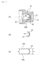
- Figs. 2 (a) to (f) are respectively axial sectional views of one portion including a filter
- Fig. 2 (f) are an axial sectional view of one portion including the filter, and a plan view of the filter.
- each of the filters 20 shown in Fig. 2 (a) to (f) is made of stainless steel and is formed by working and deforming a flat plate having a required number of holes (for example, 5 to 25 holes per 1cm 2 ).
- a filter 20 shown in Fig. 2 (a) has a convex portions 41, 42 and a concave portion 43 on a surface thereof in the first rupturable plate 22 side. Since the convex portion 42 is an annular projection, the concave portion 43 forms an annular groove. The convex portion 41 is a single independent projection.
- a filter 20 shown in Fig. 2(b) has a convex portion 41, and concave portions 43, 44 on a surface thereof in the first rupturable plate 22 side. Since the convex portion 41 is an annular projection, the concave portion 44 forms an annular groove. The concave portion 43 is a single independent recess.
- a filter 20 shown in Fig. 2(c) has a convex portion 41 and a concave portion 43 on a surface thereof in the first rupturable plate 22 side. Since the convex portion 41 is an annular projection, the concave portion 43 forms a single independent recess.
- a filter 20 shown in Fig. 2 (d) has a convex portion 41 and a concave portion 43 on a surface thereof in the first rupturable plate 22 side. Since the convex portion 41 is a cylindrical projection, the concave portion 43 forms an annular groove surrounding the projection 41.
- a filter 20 shown in Fig. 2 (e) has convex portions 41, 42 and concave portions 43, 44 on a surface thereof in the first rupturable plate 22 side. Since the convex portion 41 is a cylindrical projection and the convex portion 42 is an annular projection, the concave portion 43 forms an annular groove interposing between the convex portions 41 and 42, and the concave portion 44 forms an annular groove surrounding the convex portion 42.
- a filter 20 shown in Fig. 2 (f) has plural convex portions 41 on a surface thereof and the concave portion 43 on the remaining surface in the first rupturable plate 22 side.
- the projections 41 are respectively independent projections, as shown with the plan view.
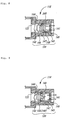
- Fig. 3 (a) is an axial sectional view of one portion including a filter
- Fig. 3(b) is a sectional view of a filter of another embodiment
- Fig. 3(c) is a sectional view of a filter of another embodiment.
- filters 20 shown in Figs. 3 (a) to (c) are made of stainless steel, and have a semi-spherical shape or a shape similar thereto with a required number of holes (for example, 10 to 20 holes per 1 cm 2 with a flat plate conversion).
- a screen 21 and a filter 20 are arranged in a pressurized gas flow path 15 inside the diffuser portion 16 in a state that they are in contact with each other.
- the screen 21 comprises a wire mesh made of stainless steel and it is fixed to an inner wall surface of the diffuser portion 16 by welding or the like.
- the filter 20 is arranged in a state that its opening portion is directed to the first rupturable plate 22 side and its spherical surface is in contact with the screen 21.
- the filter 20 is fitted into the pressurized flow path 15 before mounting the screen 21 and it is not fixed yet.
- Fig. 3(b) shows a semi-spherical filter 20 shown in Fig. 3(a) provided at its inner surface with a required number of projections 41.
- the projection may be arranged as shown in Figs. 2 (a) to (f), and, for example, it may be formed in an annular projection such as the convex portion 41 in Fig. 2 (b), or it may be formed in plural independent projections as the projections 41 in Fig. 2(f).
- the semi-spherical filter 20 shown in Figs. 3 (a) and (b) has an extension portion 20a in which a peripheral edge of the opening portion is extended, as shown in Fig. 3 (c), and an outer diameter d2 of the extension portion 20a may be smaller than an outer diameter d1 of the filter 20.
- an inner diameter of the pressurized gas flow path 15 is approximately equal to the diameter d1 of the filter 20.
- the filter 20 By providing the filter 20 with such an extension portion 20a as shown in Fig. 3(c), a work for fitting the filter 20 into the pressurized gas flow path 15 in the diffuser portion 16 before mounting the screen 21 can be facilitated, even from the screen 21 side or even from the opening portion side of the filter 20.
- the above relationship between the outer diameter d1 of the filter 20 and the outer diameter d2 of the extension portion 20a is preferable, because fitting is made easy.
- Fig. 4(a) is an axial sectional view of one portion including a filter
- Fig. 4(b) is a sectional view of a filter of another embodiment
- Fig. 4(c) is a sectional view for explaining a method of mounting a filter of another embodiment.
- the filters 20 shown in Figs. 4 (a) to (c) are made of stainless steel and have a semi-spherical shape or a shape similar thereto with a required number of holes (for example, 10 to 20 holes per 1 cm 2 if converted into a flat plate).
- a screen 21 and a filter 20 are arranged to be in contact with each other in a pressurized gas flow path 15 inside the diffuser portion 16.
- the screen 21 comprises a wire mesh made of stainless steel and it is fixed to an inner wall surface of the diffuser portion 16 by welding or the like.
- the filter 20 is arranged in such a state that its spherical surface is directed to the first rupturable plate 22 side and its peripheral edge of the opening portion is in contact with screen 21.
- the filter 20 has been fitted into the pressurized flow path 15 before mounting the first rupturable plate 22 and it is not fixed yet.
- Fig. 4(b) shows a filter 20 formed by providing an outer surface of the semi-spherical filter 20 shown in Fig. 4(a) with a required number of projections 41.
- the projection may be arranged as shown in Figs. 2 (a) to (f), and, for example, it may be formed in an annular projection such as the convex portion 41 in Fig. 2(b), or it may be formed in plural independent projections as the projections 41 in Fig. 2(f).
- the semi-spherical filter 20 shown in Fig. 4(a) and (b) has an extension portion 20a in which a peripheral edge of an opening portion is extended, as shown in Fig. 4(c), and an outer diameter of the extension portion 20a may be smaller than an outer diameter of the filter 20 as in the case of Fig. 3(c).
- the fragments are collected in the vicinity of a portion where an outer surface of the filter 20 and an inner wall surface 16a of the diffuser portion 16 come in contact with each other and a portion around a top of the filter is not in contact with fragments at this time, and thereby securing of a flow path for the pressurized gas is made easier. Further, since many holes formed in the filter 20 are not blocked, adjustment of a flow amount of the pressurized gas conducted by many holes is made easy.
- the opening portion 13 and the diffuser portion 16 are formed to be concentric with the center axis of the housing 12, but, for example, the opening portion 13 and the diffuser portion 16 may be formed to be eccentric with the center axis of the housing 12 at one end portion of the housing 12, or the opening portion 13 or the diffuser portion 16 may be formed in the peripheral wall portion of the housing 12.
- a shape of the housing 12 is not limited to that shown in Fig. 1 but it may be long in the radial direction.
- the inflator 10 is mounted as a system, being combined with an activation signal-outputting means comprising an impact sensor and a control unit and a module case or the like accommodating the inflator 10 and an air bag (for example, a curtain-like air bag) therein.
- the air bag is connected at an outer peripheral surface of the diffuser portion 16 in the gas discharging port 18 side.
- the igniter 28 Upon receiving a signal from the impact sensor in the above system when the vehicle receives an impact, the igniter 28 is activated, and a priming is ignited and burnt to ignite and burn the gas generating agent 25 in the combustion chamber 24, so that a combustion gas with a high temperature is generated.
- the second rupturable plate 30 is ruptured due to generation of the combustion gas, and the combustion gas flows into the internal space 14 through the combustion gas flow path 32 to increase a pressure. Since the first rupturable plate 22 is ruptured due to pressure rising in the internal space 14, so that the opening portion 13 is opened, the pressurized gas flows out from the gas discharging port 22 through the filter 20 to inflate the air bag. In this course, fragments of the first rupturable plate 22 are captured by the filter 20, as described above, and outflow of the pressurized gas is not blocked.
- FIG. 7 is a sectional view showing an inflator 110 according to the present invention, taken along an axial direction of a housing.
- the inflator 110 shown in Fig. 7 is different in shape, structure and arrangement of the filter 120 from the conventional inflator shown in Fig. 1, but the other constitution or structure thereof is substantially the same as that shown in Fig. 1.
- the inflator 110 will be described generally as follows.
- an opening portion 113 is provided at one end of a cylindrical inflator housing 112, and the opening portion 113 is closed by a first rupturable plate 122.
- the first rupturable plate 122 is fixed to the inflator housing 112 or a diffuser portion 116 by resistance-welding or the like.
- a pressurized gas such as argon, helium, or nitrogen gas is charged in an internal space 114 of the inflator housing 112.
- a charging pressure of the pressurized medium is about 20,000 to 65,000 kPa.
- a combustion chamber 124 surrounded by a combustion chamber housing 126 is provided in the cylindrical inflator housing 112 at an opposite side (hereinafter, referred to as in the other end side) to the side in which the opening portion 113 is provided, and a required amount of solid gas generating agent 125 is accommodated in the combustion chamber 124.
- An igniter 128 for igniting and burning the gas generating agent 125 is provided inside the combustion chamber 124.
- a combustion gas flow path 132 for communicating the combustion chamber 124 with the internal space 114 charged with the pressurized gas is closed by a second rupturable plate 130.
- the second rupturable plate 130 is fixed to the combustion chamber housing 126 by resistance-welding or the like.
- the diffuser portion 116 having a gas discharging port 141 is connected to the opening portion 113 provided in the inflator housing 112.
- the diffuser portion 116 may be formed integrally with the inflator housing, as shown in the drawing, or alternatively it may be formed as an independent member from the inflator housing, being separated at a certain portion.
- a diffuser portion 116 can be made as a member independent from the inflator housing 112, being separated along the chain line connecting A-A' portion in Fig. 7 or a portion thereabout.
- an amount of a gas to be discharged through the gas discharging port 141 is adjusted. That is, the total opening area of the gas discharging port 141 is smaller than the total opening area of the opening portion 113 or the total opening area of the communication holes 147.
- the interior of the diffuser portion 116 is formed to be hollow, a pressurized gas flow path 144 is defined between the gas discharging port 141 and the first rupturable plate 22, and the pressurized gas flow path 144 is closed before activation of the inflator.
- a filter 120 is provided in the interior of the pressurized gas flow path 144.
- the filter 120 shown in this embodiment is formed in a substantially cylindrical shape as a whole and in a cap shape having an axial one end portion closed and the other end portion opened, and the closed one end portion is defined as a closed portion 142 and the opened end portion opposite thereto is defined as an opened portion 143.
- a side wall portion namely, a peripheral wall portion 145
- plural communication holes 147 are provided in a range of the side wall portion spaced from an end portion in the opening side (namely, the opened portion 143).
- the filter 120 shown in this embodiment is formed with an expanded portion 148 obtained by expanding the peripheral wall portion 145 on the side of the opening portion 143 in the radial direction so as to increase the diameter thereof.
- the filter 120 is mounted by abutting a distal end (namely, the opened portion 143) of the expanded portion 148 against the wall 146 provided with the gas discharging port 141 to weld the distal end to the wall.
- a distal end namely, the opened portion 143
- the wall 146 provided with the gas discharging port 141
- fixation is conducted by resistance welding, because the fixation is easily performed.
- the diffuser portion 116 and the inflator housing 112 are formed as an independent member, being separated along the chain line connecting the A-A' portion in Fig.
- the filter 120 is arranged in the gas flow path 144 from the side in which the opening portion 113 is formed such that the opened portion 143 is directed to the gas discharging port 141 and the expanded portion 148 and the wall 146 are fixed to each other by resistance-welding.
- the communication holes 147 are formed in the portion other than the expanded portion 148 in a peripheral portion 145. Therefore, when the filter 120 is disposed in the gas flow path 144, a pocket portion 140 which can store fragments of the rupturable plate is formed between the an outer peripheral surface of the expanded portion 148 and an inner surface (namely, a surface defining a radial outer surface of the gas flow path 144) of the diffuser portion 116. Further, since no communication hole 147 is formed in the expanded portion 148, the pocket portion 140 with a depth corresponding to the length of the expanded portion 148 in its axial direction thereof is formed.
- the fragments of the rupturable plate or the like are stored in the pocket portion and a surface (particularly, the communication holes 147) of the filter is not covered with the fragments or the like, a flow path for the pressurized gas is always secured so that an inflator in which a flow amount is not changed is realized.
- Figs. 8 to 11 are respectively axial sectional views of one portions including a filter in an inflator, which shows states, particularly, at a time of activation, namely after the rupturable plate 122 has been ruptured.
- a thick arrow line in each drawing indicates a flow direction of a gas.
- the same members as those in Fig. 7 are attached with same numerals and explanation thereof will be omitted.
- a filter 120 constituted to include an expanded portion 148 is used, and particularly, the filter 120 is formed in a skirt shape having an inclining portion whose diameter is gradually increased.
- an outer diameter of the distal end (namely, the opened portion 143) of the expanded portion 148 is made slightly smaller than an inner diameter of the gas flow path 144 of a portion in which the opened portion 143 exists, so that positioning can be performed when the filter is disposed in the gas flow path 144.
- a gas discharging port 141 formed in the diffuser portion 116 is formed to comprise plural small holes, but the gas discharging port 141 may be formed as a single opening in the same manner as the inflator shown in Fig. 7 described above.
- the filter 120 is fixed by directing the closed portion 142 to the rupturable plate 122 side and resistance-welding a distal end (the opened portion 143) of the expanded portion 148 to a wall 146 provided with the gas discharging port 141.
- the pocket portion 140 with a depth corresponding to the axial length of the expanded portion 148 is formed.
- an inflator 120 in which the whole of the peripheral wall portion 145 corresponds to the expanded portion 148 can be used. Even in this case, by forming an outer diameter of an end portion of the opened portion 143 to be slightly smaller than an inner diameter of the gas flow path 144 in a portion where the opened portion 143 exists, positioning at a time of assembling the filter 120 can be performed easily.
- the communication holes 147 are necessarily provided in the peripheral wall portion 145 formed as the expanded portion 148, but they are formed in a portion far from the opened portion 143. Therefore, a pocket portion 140 which can store fragments of the rupturable plate therein is formed between an outer peripheral surface of the expanded portion 148 and an inner peripheral surface of the diffuser portion 116 in the vicinity of the opened portion 143. Thereby, due to that fragments or the like included in the gas are stored in the pocket portion 140 to be removed from the gas, and a flow path for the pressurized gas is always secured so that an inflator in which a flow amount is constant is realized.
- the expanded portion can be formed in an outward flange-like shape, as show in Fig. 10. That is, a filter 120 used in the inflator shown in Fig. 10 has such a structure that its peripheral wall portion 145 is reduced in diameter toward the opened portion 143 and an expanded portion 148 extending outwardly in the radial direction is formed at an end portion of the opened portion 143.
- the expanded portion 148 is formed in an outward flange shape, and therefore, if its outer diameter is formed to be slightly smaller than an inner diameter of the gas flow path 144 in a portion where the expanded portion 148 exits, positioning at a time of assembling the filter 120 into the gas flow path 144 can be made easily.
- the filter 120 is fixed by resistance-welding a portion of the flat expanded portion 148 to a wall 146 provided with the gas discharging port 141.
- the communication holes 147 are formed in a portion far from the opened portion 143 of the peripheral wall portion 145 reduced in diameter and the pocket portion 140 is formed between an outer peripheral surface of the peripheral wall portion 145 which is not formed with the communication holes 147 and an inner peripheral surface of the diffuser portion 116.
- fragments included in a gas and the like are stored in the pocket portion 140.
- the fragments and the like are removed from the gas and a flow path for the pressurized gas is always secured, so that an inflator in which a flow amount is constant is realized.
- Fig. 11 shows an inflator formed with a filter 120 having no expanded portion.
- the filter 12 is fixed by resistance-welding the distal end of the opened portion 143 to the wall 146 provided with the gas discharging port 141.
- the communication holes 147 are formed in a portion far from the opened portion 143 of the peripheral wall portion 145, and a pocket portion 140 is formed between an outer peripheral surface of the peripheral wall portion 145 in a portion where the communication holes 147 are not provided and an inner peripheral surface of the diffuser portion 116.
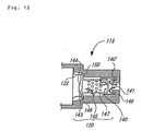
- Fig. 12 shows an inflator in which an opened portion 143 of the filter 120 is directed to the rupturable plate 122 side and the closed portion 142 is directed to the gas discharging port 141 side.
- the filter 120 shown in this drawing is formed at an end portion of the opened portion 143 with an expanded portion 148 extending outwardly in the radial direction, and the filter is fixed by engaging the expanded portion 148 with a step portion 150 formed inside the gas flow path 144.
- the filter 120 can be fixed by pressure-fitting the same into the gas flow path.
- the closed portion 142 of the filter 120 is directed to the gas discharging port 141 and the pressure-fitting is performed from the opened portion 143 side.
- the step portion 150 is formed to have a periphery which is gradually reduced in inner diameter toward the closed end, namely toward the gas discharging port 141, pressure-fitting of the filter 120 can be performed easily.
- the communication holes 147 are formed in a portion far from the closed portion 142 of the peripheral wall portion 145, and the pocket portion 140 is provided in the closed portion 142 side inside the filter 120.
- a continuous projection is formed on the wall surface 146 having the gas discharging port 141 inside the diffuser portion 116, so that a second pocket portion 140' can be defined between the projection and an inner wall surface of the diffuser portion.
- the second pocket portion is formed annularly outside the projection surrounding the gas discharging port 141.
- the direction of a gas discharged from the filter 120 is further changed largely at the second pocket portion 140', so that fragments and residues are further arrested in the second pocket portion 140'.
- the inflator including the solid gas generating agent has been described, but the present invention can be applied to a structure in which fragments of a rupturable plate are arrested in an inflator (for example, an inflator in which a rupturable plate is ruptured by an activation output of an electrical igniter) including only a pressurized gas as a gas generating source and having an opening portion closed by a rupturable plate.
- an inflator for example, an inflator in which a rupturable plate is ruptured by an activation output of an electrical igniter
- the inflator of the present invention can be employed as various inflators such as an inflator for a driver side, an inflator for a passenger side next to the driver, an air bag inflator for a side collision, an inflator for a curtain air bag, an inflator for a knee-bolster air bag, an inflator for an inflatable seat belt, an inflator for a tubular system and an inflator for a pretensioner, and the filter for an inflator of the present invention can be applied to the above-described various inflators.
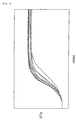
- a mixture of argon, oxygen and helium was used as the pressurized gas (a charging pressure of 30,000 kPa), and 1 g of nitramine based gas generating agent was used as the gas generating agent.
- a screen having 24 holes (a diameter of about 1.5mm) per 1cm 2 was used as the screen 21.
- 60L tank test was conducted with this inflator.
- the inflator was placed in a sealed pressure resistant container with a volume of 60 L (incidentally, the inflator was electrically connected outside the tank), and a pressure change when the inflator was activated in the atmosphere with a temperature of 23°C was measured. The test was conducted 10 times totally. A result thereof is shown in Fig. 5.
Landscapes
- Physics & Mathematics (AREA)
- Fluid Mechanics (AREA)
- Engineering & Computer Science (AREA)
- Mechanical Engineering (AREA)
- Air Bags (AREA)
Applications Claiming Priority (5)
| Application Number | Priority Date | Filing Date | Title |
|---|---|---|---|
| JP2002163908 | 2002-06-05 | ||
| JP2002163908 | 2002-06-05 | ||
| JP2002362784 | 2002-12-13 | ||
| JP2002362784A JP4209184B2 (ja) | 2002-06-05 | 2002-12-13 | インフレータ |
| PCT/JP2003/007151 WO2003104045A1 (ja) | 2002-06-05 | 2003-06-05 | インフレータ |
Publications (2)
| Publication Number | Publication Date |
|---|---|
| EP1510419A1 true EP1510419A1 (de) | 2005-03-02 |
| EP1510419A4 EP1510419A4 (de) | 2008-12-31 |
Family
ID=29738320
Family Applications (1)
| Application Number | Title | Priority Date | Filing Date |
|---|---|---|---|
| EP03736042A Withdrawn EP1510419A4 (de) | 2002-06-05 | 2003-06-05 | Aufblasvorrichtung |
Country Status (3)
| Country | Link |
|---|---|
| EP (1) | EP1510419A4 (de) |
| JP (1) | JP4209184B2 (de) |
| WO (1) | WO2003104045A1 (de) |
Families Citing this family (10)
| Publication number | Priority date | Publication date | Assignee | Title |
|---|---|---|---|---|
| GB2417066B (en) * | 2004-08-13 | 2006-12-06 | Autoliv Dev | Improvements in or relating to an inflator for an air-bag |
| JP2006111257A (ja) * | 2004-09-17 | 2006-04-27 | Daicel Chem Ind Ltd | ガス発生器 |
| JP2006160049A (ja) * | 2004-12-07 | 2006-06-22 | Daicel Chem Ind Ltd | エアバッグ用小型インフレータ |
| US20070176404A1 (en) * | 2006-01-30 | 2007-08-02 | Takata Corporation | Stored gas inflator |
| JP2013043595A (ja) | 2011-08-25 | 2013-03-04 | Takata Corp | インフレータ |
| JP6313031B2 (ja) * | 2013-02-22 | 2018-04-18 | 株式会社ダイセル | ガス発生器 |
| CN108602486B (zh) * | 2016-01-25 | 2021-05-04 | 株式会社大赛璐 | 气体发生器 |
| JP6691442B2 (ja) | 2016-06-27 | 2020-04-28 | 株式会社ダイセル | ガス発生器 |
| JP6934372B2 (ja) | 2017-09-05 | 2021-09-15 | 株式会社ダイセル | ガス発生器 |
| DE102022124029A1 (de) * | 2022-09-20 | 2024-03-21 | Zf Airbag Germany Gmbh | Gasgenerator |
Family Cites Families (8)
| Publication number | Priority date | Publication date | Assignee | Title |
|---|---|---|---|---|
| FR2589737A1 (fr) | 1985-11-12 | 1987-05-15 | Dow Corning Sa | Procedes de fabrication de pansements |
| US5031932A (en) * | 1990-04-05 | 1991-07-16 | Frantom Richard L | Single pyrotechnic hybrid inflator |
| EP0796179B1 (de) | 1994-12-12 | 2001-04-11 | Atlantic Research Corporation | Hybrid-gasgenerator |
| US5820162A (en) * | 1996-03-21 | 1998-10-13 | Airbelt Systems, Llc. | Airbag system inflator |
| JP2000225914A (ja) * | 1999-02-02 | 2000-08-15 | Nippon Kayaku Co Ltd | ガス発生器 |
| JP5050298B2 (ja) * | 2000-05-19 | 2012-10-17 | タカタ株式会社 | ガス発生装置 |
| US7252303B2 (en) * | 2000-08-29 | 2007-08-07 | Daicel Chemical Industries, Ltd. | Inflator |
| JP2002079902A (ja) * | 2000-09-08 | 2002-03-19 | Daicel Chem Ind Ltd | インフレータ |
-
2002
- 2002-12-13 JP JP2002362784A patent/JP4209184B2/ja not_active Expired - Lifetime
-
2003
- 2003-06-05 EP EP03736042A patent/EP1510419A4/de not_active Withdrawn
- 2003-06-05 WO PCT/JP2003/007151 patent/WO2003104045A1/ja not_active Ceased
Also Published As
| Publication number | Publication date |
|---|---|
| JP2004058984A (ja) | 2004-02-26 |
| WO2003104045A1 (ja) | 2003-12-18 |
| EP1510419A4 (de) | 2008-12-31 |
| JP4209184B2 (ja) | 2009-01-14 |
Similar Documents
| Publication | Publication Date | Title |
|---|---|---|
| US5882036A (en) | Hybrid inflator with reduced solid emissions | |
| CN100348443C (zh) | 用于气囊的气体发生器以及气囊装置 | |
| US5615912A (en) | Inflator for air bag | |
| US8011303B2 (en) | Gas generator | |
| US7390019B2 (en) | Inflator for airbag | |
| US5624133A (en) | Prefilter for gas generating air bag inflator | |
| WO2007032387A1 (ja) | ガス発生器 | |
| US6959649B2 (en) | Inflator | |
| US7052039B2 (en) | Inflator | |
| JP2012076608A (ja) | ガス発生器 | |
| EP1510419A1 (de) | Aufblasvorrichtung | |
| EP1479573A2 (de) | Gassackmodul mit Druckregler | |
| US6231080B1 (en) | Gas generator for air bag and air bag system | |
| JPH11217055A (ja) | ガス発生器 | |
| US6224098B1 (en) | Gas generator for air bag and air bag system | |
| US7222880B2 (en) | Inflator | |
| US20070001439A1 (en) | Gas generator for air bag | |
| US5199741A (en) | Method of assembling an inflator | |
| JPH1095302A (ja) | エアバッグ用ガス発生器及びエアバッグ装置 | |
| US6007098A (en) | Low cost pyrotechnic inflator | |
| JPWO2002024493A1 (ja) | ガス発生器 | |
| JP2007131077A (ja) | エアバッグ用ガス発生器 | |
| JP3742603B2 (ja) | 多段式エアバッグ用ガス発生器及びエアバッグ装置 | |
| JP3953300B2 (ja) | エアバッグ用ガス発生器のリテーナー及びこれを用いたエアバッグ用ガス発生器 | |
| CN120245910A (zh) | 一种单级圆柱形气体发生器 |
Legal Events
| Date | Code | Title | Description |
|---|---|---|---|
| PUAI | Public reference made under article 153(3) epc to a published international application that has entered the european phase |
Free format text: ORIGINAL CODE: 0009012 |
|
| 17P | Request for examination filed |
Effective date: 20041124 |
|
| AK | Designated contracting states |
Kind code of ref document: A1 Designated state(s): AT BE BG CH CY CZ DE DK EE ES FI FR GB GR HU IE IT LI LU MC NL PT RO SE SI SK TR |
|
| RBV | Designated contracting states (corrected) |
Designated state(s): DE FR |
|
| RIN1 | Information on inventor provided before grant (corrected) |
Inventor name: IWAI, YASUNORI C/O DAICEL CHEM IND. LTD Inventor name: TOKUDA, MASAKAZUDAICEL CHEM. IND. LTD Inventor name: SHIOJI,HIROSHI,DAICEL CHEM.IND LTD. |
|
| RAP1 | Party data changed (applicant data changed or rights of an application transferred) |
Owner name: DAICEL CHEMICAL INDUSTRIES, LTD. |
|
| A4 | Supplementary search report drawn up and despatched |
Effective date: 20081201 |
|
| STAA | Information on the status of an ep patent application or granted ep patent |
Free format text: STATUS: THE APPLICATION IS DEEMED TO BE WITHDRAWN |
|
| 18D | Application deemed to be withdrawn |
Effective date: 20090303 |