EP1510383A2 - Aus Kunststoff gespritzte Führungsschiene - Google Patents
Aus Kunststoff gespritzte Führungsschiene Download PDFInfo
- Publication number
- EP1510383A2 EP1510383A2 EP04018091A EP04018091A EP1510383A2 EP 1510383 A2 EP1510383 A2 EP 1510383A2 EP 04018091 A EP04018091 A EP 04018091A EP 04018091 A EP04018091 A EP 04018091A EP 1510383 A2 EP1510383 A2 EP 1510383A2
- Authority
- EP
- European Patent Office
- Prior art keywords
- guide rail
- connecting means
- guide groove
- guide
- arrangement according
- Prior art date
- Legal status (The legal status is an assumption and is not a legal conclusion. Google has not performed a legal analysis and makes no representation as to the accuracy of the status listed.)
- Granted
Links
Images


Classifications
-
- B—PERFORMING OPERATIONS; TRANSPORTING
- B60—VEHICLES IN GENERAL
- B60J—WINDOWS, WINDSCREENS, NON-FIXED ROOFS, DOORS, OR SIMILAR DEVICES FOR VEHICLES; REMOVABLE EXTERNAL PROTECTIVE COVERINGS SPECIALLY ADAPTED FOR VEHICLES
- B60J1/00—Windows; Windscreens; Accessories therefor
- B60J1/18—Windows; Windscreens; Accessories therefor arranged at the vehicle rear
-
- B—PERFORMING OPERATIONS; TRANSPORTING
- B60—VEHICLES IN GENERAL
- B60J—WINDOWS, WINDSCREENS, NON-FIXED ROOFS, DOORS, OR SIMILAR DEVICES FOR VEHICLES; REMOVABLE EXTERNAL PROTECTIVE COVERINGS SPECIALLY ADAPTED FOR VEHICLES
- B60J1/00—Windows; Windscreens; Accessories therefor
- B60J1/20—Accessories, e.g. wind deflectors, blinds
- B60J1/2011—Blinds; curtains or screens reducing heat or light intensity
- B60J1/2013—Roller blinds
- B60J1/2066—Arrangement of blinds in vehicles
- B60J1/2075—Arrangement of blinds in vehicles specially adapted for fixed windows
- B60J1/208—Arrangement of blinds in vehicles specially adapted for fixed windows for rear windows
-
- B—PERFORMING OPERATIONS; TRANSPORTING
- B60—VEHICLES IN GENERAL
- B60J—WINDOWS, WINDSCREENS, NON-FIXED ROOFS, DOORS, OR SIMILAR DEVICES FOR VEHICLES; REMOVABLE EXTERNAL PROTECTIVE COVERINGS SPECIALLY ADAPTED FOR VEHICLES
- B60J1/00—Windows; Windscreens; Accessories therefor
- B60J1/20—Accessories, e.g. wind deflectors, blinds
- B60J1/2011—Blinds; curtains or screens reducing heat or light intensity
- B60J1/2013—Roller blinds
- B60J1/2019—Roller blinds powered, e.g. by electric, hydraulic or pneumatic actuators
- B60J1/2027—Roller blinds powered, e.g. by electric, hydraulic or pneumatic actuators with a buckle-proof guided flexible actuating element acting on the draw bar for pushing or push-pulling, e.g. a Bowden cable
-
- B—PERFORMING OPERATIONS; TRANSPORTING
- B60—VEHICLES IN GENERAL
- B60J—WINDOWS, WINDSCREENS, NON-FIXED ROOFS, DOORS, OR SIMILAR DEVICES FOR VEHICLES; REMOVABLE EXTERNAL PROTECTIVE COVERINGS SPECIALLY ADAPTED FOR VEHICLES
- B60J1/00—Windows; Windscreens; Accessories therefor
- B60J1/20—Accessories, e.g. wind deflectors, blinds
- B60J1/2011—Blinds; curtains or screens reducing heat or light intensity
- B60J1/2013—Roller blinds
- B60J1/2036—Roller blinds characterised by structural elements
- B60J1/2052—Guides
Definitions
- DE 100 57 759 A1 shows a rear window blind for Motor vehicles.
- To the rear window blind is one below the hat rack rotatably mounted winding shaft on the with an edge of the roller blind is attached.
- the roller blind is roughly trapezoidal in shape and with its other, attached from the winding shaft edge attached to a pull rod.
- the tie rod is laterally in two guide rails guided, which glued to the inside of the rear window or hidden behind the C-pillar trim in the body are. In the guide rails flexurally elastic run Thrust members that are kink-proof in the guide rails are guided.
- the guide rails consist of an aluminum extruded profile, the one continuous undercut Groove contains.
- the groove is composed of a circular Cross-sectional portion and a rectangular, wherein the rectangular is narrower than the diameter of the circle corresponds.
- the rectangular section forms the slot over which the guide groove outwards is open.
- Sliding or guiding bodies run in the guide rails, which have a head which in cross section to the adjusted circular portion of the guide rail profile is.
- This head is either in the shape of a ball or a short cylindrical piece that is so sized is that it is in the curved sections of the guide rails not stuck.
- the diameter of the neck is like that Measure that it is free from jamming through the slot of the guide groove fits.
- the head of the guide part of the pull-out profile consists usually made of a molded plastic.
- the friction pairing from the plastic guide bodies and The aluminum rail is also not optimal.
- the guide rail assembly composed of two parts. Of the a part forms the outer part, which is made of an elastic deformable material is made. The other part serves as a support part and consists of a less malleable Material to make sure that the outer part, which contains the undercut guide groove, is stabilized so that over time the Slot width of the guide not changed.
- the outer part may have a narrow, elongated shape, the substantially the shape of the guide groove follows.
- the connecting means between the support member and the Outer part may be formed by locking means.
- This locking means include, for example, a hook, which is as behind-grip Bar can be executed. Complementary lanyards are provided on the support part. Also here In turn, an undercut bar can be used. An undercut bar puts at the support part no problem, as far as, for example, as an extruded profile is subsequently produced in the desired Shape is bent.
- the material of the outer part is preferably made of a Group of thermoplastics selected. This will be the desired yield generated, with the risk of possible deformation over time by the support member is encountered.
- the support part has an area which in the assembled state the guide groove, at least in sections, supported laterally on the flanks.
- the support part contains a groove which is U-shaped is and has parallel edges.
- the support member may be made of a light metal be.
- the guide rail assembly of a first and a second part is made, both made as a molded part are, with the fugue, where the two parts together are joined, extend in the longitudinal direction of the guide groove. This allows the two parts, each for themselves, free from Undercut be held. Only after joining the Both parts creates the undercut guide groove for the blind.
- each part is free from undercuts is again the possibility of one of the two parts with a section of the interior trim, for example integrally integrating the C-pillar, i. this part of the guide rail assembly with the plate-shaped Part of the side panel to inject in one piece.
- the connecting means can also be over the entire Length of the two parts extend.
- the connecting means can also be over the entire Length of the two parts extend.
- one of the connecting means in one Strip while the other connecting means a groove is.
- To a positioning in the longitudinal direction of the guide To reach the ledge can carry tenons, which in additional Engage opening in the groove.
- a support member may be provided, the made of a less deformable material and that on the two parts are put on. It serves a delay prevent the plastic moldings. This delay can be caused by aging or age-related wasting become.
- the support parts stabilize the groove and make sure that the slot of the guide groove over the Length maintained a constant width.
- the two parts can be together, at least in sections be connected cohesively.
- cohesive Joining come laser welding, ultrasonic welding, Gluing or other joining techniques in Question.
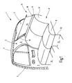
- Fig. 1 illustrates the broken, truncated rear area a car.
- the figure illustrates a Look at the right inside, which is not illustrated left inside is mirror image.
- the Presentation is simplified, for example, body Internal structures, such as stiffeners and fasteners not shown because of their representation for understanding the invention is not required.
- the illustrated body section 1 includes Roof 2, from the side of a B-pillar 3 down to a floor group, not shown leads. A corresponding B-pillar would be on the broken side of the vehicle too think.
- the roof 2 goes at its rear edge in a rear window 4 over. Laterally, the rear window 4 ends at one C-pillar 5, which is located at a distance from the B-pillar 3.
- the C-pillar 5 carries an inner lining 6.
- a rear seat 8 At the height of the rear, right side door 7 is located a rear seat 8, to which a seat 9 and a rear seat back 11 belong.
- the rear seat 9 lies on a base surface 12 leading to the floor assembly heard and trained in the front of the rear seat 9 foot wells 13 are.
- a rear window roller blind 14 On the inside in front of the rear window 4 is located a rear window roller blind 14. From the rear window roller blind 14 is its partially extended roller blind as well as one of the lateral To recognize guide rails 16. The guide rail 16 begins at an existing behind the rear seat back 11 Hat rack 17 and runs next to the side edge of the window. In addition, the hat rack 17 contains a continuous Pull-out slot 18 from which the roller blind 15 runs out.
- winding shaft 19 rotatably mounted on the with an edge of the blind sheet 15 is attached.
- the winding shaft 19 is by means of a schematically indicated spring motor 21 in the sense of winding the roller blind 15 on the winding shaft 19 biased.
- This is a coil spring provided anchored at one end of the body and the other end is set in the winding shaft 19.
- the roller blind 15 has an approximately trapezoidal blank on and is at their remote from the winding shaft 19 Edge provided with a tubular loop 22. Through the tubular loop 22 performs a pull-out profile or bow, in the guide pieces 23 and 24th are mounted telescopically.
- the guide pieces 23 and 24 have a neck portion 25 which has a smaller diameter has as an adjoining guide member 26, which has the shape of a short cylindrical Section has.
- the guide pieces 26 run in the Guide rails 16, next to the two side edges of the Rear window 4 are arranged. The structure of the guide rails 16 is explained below with reference to FIGS. 3 and 4.
- Each of the guide rails 16 includes a guide groove 27, which extends in the direction of the roller blind 15 in a guide slot 28 opens.
- each guide rail 16 is with a Guide tube 29, 30 connected, in which kink-resistant two flexible thrust members 31 and 32 are guided.
- the bendable Thrust members 31 and 32 are so-called Suflex waves. She consist of a cylindrical core, of a helically extending rib is surrounded. To this Way is a kind of flexible racks with all-round teeth receive.
- the guide tubes 29 and 30 connect the guide rails 16 with a gear motor 33.
- the geared motor 33 consists of a permanently excited DC motor 34 and a gear 35 together on the output shaft 36 a spur gear 37 rotatably seated.
- the gear 37 meshes with the two push members 31 and 32 positively. These Thrust members 31 and 32 tangentially to the diametrically opposite sides of the spur gear 37 over and are for this purpose in corresponding holes 38 and 39 guided.
- Thrust members 31, 32 By starting the geared motor 33 are the Thrust members 31, 32 selectively advanced or withdrawn. The movement of the push members 31, 32 follow the guide pieces 23 and 24. These are using the spring motor 21 against the free ends of the thrust members 31, 32nd held adjacent, which are located in the guide grooves 27.
- Fig. 3 shows in cross section the structure of the guide rails 16th
- Fig. 3 is the guide rail 16 of an outer part 41 and a Support member 42 together.
- the outer part 41 consists of a thermoplastic and goes in one piece in the Interior trim 6 of the C-pillar 5 via.
- the outer part 41 includes the undercut guide groove 27, which is about the slot 28 opens to the outside. Seen in cross-section mentally sets the guide groove 27 of a circular Section 43 and a rectangular section 44 together.
- the diameter of the circular portion 43 is adapted to the diameter of the guide pieces 26.
- the outer part 41 shows an outer or Sichseite 45th on, approximately parallel to a rear 46 runs.
- the Outside 45 is through the slot 28 in a section 45 a and a section 45 b divided.
- the outer part 41 forms a the rear 46 projecting wall portion 47, at its free end passes over a wall portion 48, the one Circle section follows.
- the wall section 48 closes again a straight wall section 49 which leads to the wall section 47 is parallel and in the wall section 45 b opens.
- the structure is at the rear 46 free of undercuts, i. the Both wall sections 47 and 49 are from on the outside bounded by two mutually parallel side walls.
- a first hook strip 51 In addition to the wall portion 47 extends parallel to the longitudinal extent of the slot 48 a first hook strip 51, the, together with the wall portion 47 at the inner corner a groove 52 is created. A mirror image of this is one second hook strip 53 provided in addition to the outside of the wall portion 49 is arranged and together with the Outside of the wall portion 49 forms a groove 54.
- the dimensions of the two hook strips 51 and 53 are selected so that the outer part 41 after spraying readily from the complementary mold cavity of the injection mold can be subtracted by the elasticity of the Hook strips 51 and 53 is utilized. That way is the use of complicated tools with moving Cores for creating undercuts in this respect dispensable.
- the wall thickness in the region of the wall section 48, the cylindrical portion 43 of the cross-sectional profile surrounds, in relation to the width of the Slot 28 is chosen so that the finished molded outer part 41 of the mold core for generating the cross section 43rd and the cross-section 44 can be deducted in Direction perpendicular to the plane passing through the outside 45 a and 45 b is formed.
- the outer part 41 is in the region of the guide groove widened until the corresponding part of the mold core can slide out through the slot 28. Due to the inherent elasticity can the outer part 41 then in the original spring back planned form.
- the support member 42 is provided.
- the Support member 42 is disposed on the body, like this one schematically indicated section 55 of the inside of the Body panel reveals.
- the support member 42 sets composed of a mounting plate 56, of the two Lean legs 57 and 58.
- the legs 57 and 58 limit an interior that is suitable to play the Structure to absorb the back contour of the outer part 41 forms in the region of the guide groove 27.
- This U-shaped opening consists of an arcuate Part together, where the wall section 48 abuts, and two parallel surfaces, where the Create outside of the wall sections 47 and 49.
- the free ends of the two legs 57 and 58 are provided with flat hook noses 59 and 61, which are the hook strips 51 and 53 are complementary.
- the support member 52 consists of a relatively solid and relatively inelastic material that is capable the forces that occur in operation, the widening of the slot 28, sufficient resistance opposes.
- the support member 42 consists of an aluminum extruded profile, if applicable, below still according to the desired course, to be bent can.
- a guide rail 16 get over a great length made of plastic, with no moving core is required in the injection molding tool.
- Such Shape would be very difficult to produce and extremely expensive because at a diameter of the nikfömigen part 43 of the guide groove 27 of about 8 mm it is very difficult, this core as a movable core to a length of about 50 cm position correct to hold.
- the guide rail 16 avoids such a movable Core. Rather, the core can be rigidly attached to a bridge be who molds the slot 28.
- Another advantage of the solution according to the invention consists in that the color visible to the viewer the guide rail 16 exactly the color of the inner lining 6 corresponds. No provision needs to be made to hide a shiny aluminum rail, like this is required in the prior art.
- thermoplastic material shows more favorable Sliding properties in connection with the guide body 26. There is no longer a need for the guide body 26 necessarily made of plastic or with - To coat plastic, to favorable sliding properties to get as required when the Guide rail would consist of aluminum profile.
- the plastic surface tends to be due the compliance much less to rattling noises, than a hard metal surface.
- the metal is limited to the support member 42.
- the undeformable support member 42 ensures a long time the dimensional accuracy of the guide groove 27th
- the guide groove 27 the already explained shape in the sense that they are made of a circular section and a rectangular one Section exists, which corresponds to the slot 28.
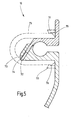
- the guide rail 16 according to FIG. 4 is in two parts, wherein a first part 63 integral with the portion 45 a and another part 64 integral with the portion 45 b connected is.
- the visible side portion 45 a is part of a flange 65, which extends to the slot 28 and there in one Wall section 66 passes.
- the wall portion 66 a terminates a surface 67 which is at an angle of about 30 to 60 Degree opposite the visible side 45 a runs.
- the flange 45 forms together with the wall portion 66 about a right-angled rail, on its side the wall portion or leg 66 on the outside, from the inner corner away side, as the figure 4 recognize makes part of the wall that forms the circular one Section section 43 corresponds and a wall section, the right-angled cross-sectional profile section 44 limited.
- the wall 67 ends approximately at the height of a plane that Referring to Fig. 4 of the upper boundary wall of the slot 28 corresponds. From this point, the wall or the Leg 66 into a narrow ledge 68 over which, as shown, protrudes beyond a plane through the center of the circular section 43 and the middle of the Slot 28 is defined.
- the other part 64 of the guide rail 16 is integrally Part of the interior trim 6 and shows in Basically a similar complementary shape as the Part 63.
- the visible side section 45 b is followed Leg 69, which is parallel to the leg 66.
- the in the leg 66 facing side of the leg 69 has an outer contour, the outer contour of the leg 66th added to the complete guide groove 67.
- the leg 69 On the opposite side of the slot 68 is the leg 69, which is a bit far above the Slot 28 surmounted, provided with a groove 71 which mounted in the Condition, as shown, the bar 68 receives. Either the bar 68 and the groove 71 extend over the entire length of the guide rail 16.
- Ribs 74 may be provided on tabs 72, which make it possible to locally the wall of the To weld opening 73 with the rib 74.
- This welding can be an ultrasonic welding by there corresponding sonotrodes are pressed, or it exists also the possibility here the parts with each other laser to weld.
- the stabilization carrier 75 is shorter than the Guide rail 16 and has a substantially U-shaped Shape up and out at its free ends pointing hooked noses 76 and 77 provided with hook strips 51 and 53 cooperate, as in a similar way is explained with reference to FIG. 3.
- the slot 28 can not expand, still reduce in width.
- stabilizers 75 can be spaced apart be plugged from each other.
- FIGS. 4 and 5 respectively, FIGS Both parts 63 and 64 in turn virtually undercut.
- the hook strips 51 and 53 have, if they are present, so slight undercuts, that without further the inherent elasticity of these hook strips 51 and 53 would suffice for them from the injection mold to take out without requiring a draggable core.
- the structure shown makes it possible to use a guide rail plastic injection using very inexpensive injection molding tools. The advantages, the with a plastic guide rail were already connected in connection with FIG. 3 explained in detail, so a repetition dispensable here is.
- the guide rails 16 according to FIGS. 3 and 4 were each explained as if they were, at least in sections, Part of the interior trim, for example the C-pillar. It goes without saying, however, that also the guide rails 16 may be formed separately from this and with not shown tabs or other locking members with correspondingly complementary locking members of the Side panel or the body can be connected. The visible side portion 45 B would then be approximately at the End point, at the in the figures shown the arcuate Course begins.
- the tabs for locking the guide rail 16 would, for example, in the case of execution according to Figures 4 and 5 in extension of the slot 28 may be arranged on the leg 69.
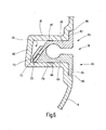
- Fig. 6 shows an embodiment of the guide rail assembly 16, which is basically the execution which Fig. 4 and 5 corresponds. However, here is the Guide rail assembly 16 inserted into a groove 78, the is formed in the side trim part 6. The side panel part 6 is thus integrally over the Groove 78 continues.
- the groove 78 is laterally of two walls 79 and 81 limited.
- the groove 78 is parallelepiped in this area.
- the two side walls 81 and 79 are through a floor 82 integrally connected.
- the guide rail arrangement 16 corresponds, as already mentioned, the guide rail assembly 16 according to FIGS. 4 and 5 and sits down from the two parts 64 and 65 together. They are training the outside of the side panel part short strip-like Flanges 83 and 84, which are in corresponding recesses 85 and 86 of the side trim part 6 flush sunk are.
- creases 87 and 88 are provided, which have a sawtooth-shaped profile and the creases on the inside of the walls 81 and 79 are complementary.
- a window blind for motor vehicles has plastic existing guide rails on.
- the guide rails are specifically designed such that injection molding tools can be used to generate the Guide groove without moving cores get along.
Landscapes
- Engineering & Computer Science (AREA)
- Mechanical Engineering (AREA)
- Window Of Vehicle (AREA)
- Operating, Guiding And Securing Of Roll- Type Closing Members (AREA)
- Support Devices For Sliding Doors (AREA)
- Moulds For Moulding Plastics Or The Like (AREA)
Abstract
Description
- Fig. 1
- eine teilweise aufgebrochene Heckpartie eines Kraftfahrzeuges, in einer perspektivischen Darstellung mit Blick gegen die Innenseite der Heckscheibe,
- Fig. 2
- den prinzipiellen Aufbau des Heckscheibenrollos nach Fig. 1,
- Fig. 3
- eine erste Führungsschienenanordnung bestehend aus einem Stützteil und einem Außenteil, in einem Schnitt quer zur Längserstreckung der Führungsnut,
- Fig. 4
- ein zweites Ausführungsbeispiel der erfindungsgemäßen Führungsschienenanordnung aus zwei miteinander gefügten Teilen, die gemeinsam die Führungsnut begrenzen, in einer ersten Höhe geschnitten quer zur Längserstreckung der Führungsnut,
- Fig. 5
- die Führungsschienenanordnung nach Figur 4, geschnitten in einer anderen Höhe, und
- Fig. 6
- eine Ausführungsform einer Führungsschienenanordnung ähnlich der nach Fig. 4, jedoch eingesetzt in eine Nut einer Seitenverkleidung.
Claims (37)
- Führungsschienenanordnung (16) für Rollos (14) und dergleichen in Kraftfahrzeugen,
mit einem Außenteil (41), das als Spritzgussteil aus elastisch verformbaren Material hergestellt ist, das erste Verbindungsmittel (51,53) aufweist und das eine hinterschnittene Führungsnut (27) enthält, die zumindest über einen Teil der Länge des Außenteils (41) durchläuft, und
mit einem Stützteil (42), das aus einem weniger verformbaren Material als das Außenteil (41) hergestellt ist und zweite Verbindungsmittel (59,61) aufweist, die mit den ersten Verbindungsmitteln (51,53) des Außenteils (41) verbindbar sind. - Führungsschienenanordnung nach Anspruch 1, dadurch gekennzeichnet, dass das Außenteil (41) überwiegend konstante Wanddicke aufweist.
- Führungsschienenanordnung nach Anspruch 1, dadurch gekennzeichnet, dass das Außenteil (41) eine schmale längliche Form aufweist, die im Wesentlichen dem Verlauf der Führungsnut (27) folgt.
- Führungsschienenanordnung nach Anspruch 1, dadurch gekennzeichnet, dass das Außenteil (41) eine flächige Gestalt aufweist, derart, dass die Abmessungen quer zu der Führungsnut (27) groß sind gegenüber der Führungsnut (27).
- Führungsschienenanordnung nach Anspruch 1, dadurch gekennzeichnet, dass das Außenteil (41) einen Teil einer Innenverkleidung (6) eines Kraftfahrzeugs bildet.
- Führungsschienenanordnung nach Anspruch 1, dadurch gekennzeichnet, dass sich der Querschnitt der Führungsnut (27) aus einem schmalen Abschnitt (44) und einem demgegenüber erweiterten Abschnitt (43) zusammensetzt, wobei der schmale Abschnitt (44) den Nutenschlitz (28) bildet.
- Führungsschienenanordnung nach Anspruch 6, dadurch gekennzeichnet, dass der schmale Abschnitt (44) parallelflankig ist.
- Führungsschienenanordnung nach Anspruch 6, dadurch gekennzeichnet, dass der erweiterte Abschnitt (43) in der Nachbarschaft zu dem schmalen Abschnitt (44) Schultern bildet, die verrundet sind oder in einem stumpfen Winkel in den schmalen Abschnitt (44) übergehen.
- Führungsschienenanordnung nach Anspruch 6, dadurch gekennzeichnet, dass der erweiterte Abschnitt (43) kreisförmig ist.
- Führungsschienenanordnung nach Anspruch 1, dadurch gekennzeichnet, dass die Führungsnut (27) und die Umgebung der Führungsnut (27) derart gestaltet sind, dass das Außenteil (41) von einem Formkern trennbar ist, der unbeweglich in einem Formnest zum Spritzen des Außenteils (41) angeordnet ist.
- Führungsschienenanordnung nach Anspruch 1, dadurch gekennzeichnet, dass die ersten Verbindungsmittel (51,53) als Rastmittel ausgebildet sind.
- Führungsschienenanordnung nach Anspruch 1, dadurch gekennzeichnet, dass die ersten Verbindungsmittel (51, 53) von wenigstens einen Haken umfassen.
- Führungsschienenanordnung nach Anspruch 1, dadurch gekennzeichnet, dass die ersten Verbindungsmittel (51,53) wenigstens eine hintergriffige Leiste umfassen, die im montierten Zustand in Richtung auf das Stützteil (42) zeigen.
- Führungsschienenanordnung nach Anspruch 1, dadurch gekennzeichnet, dass das Material des Außenteils (41) aus einer Gruppe von Thermoplasten ausgewählt ist, zu der PVC, Polypropylen, Polyethylen, Polyamid gehören.
- Führungsschienenanordnung nach Anspruch 1, dadurch gekennzeichnet, dass der Stützteil (42) einen Bereich aufweist, der im montierten Zustand die Führungsnut (27) zumindest abschnittsweise an den Flanken seitlich stützt, derart, dass der Bereich einem Aufweiten der Führungsnut (27) entgegenwirkt.
- Führungsschienenanordnung nach Anspruch 1, dadurch gekennzeichnet, dass der Stützteil (42) einen Bereich aufweist, der im montierten Zustand die Führungsnut (27) zumindest abschnittsweise in Richtung parallel zu einer Ebene unterstützt, die durch den Schlitz (28) und in die Führungsnut (27) verläuft.
- Führungsschienenanordnung nach Anspruch 16, dadurch gekennzeichnet, dass der Bereich von einem Steg gebildet ist.
- Führungsschienenanordnung nach Anspruch 1, dadurch gekennzeichnet, dass der Stützteil (42) einen über die Länge konstanten Querschnitt aufweist.
- Führungsschienenanordnung nach Anspruch 1, dadurch gekennzeichnet, dass der Stützteil (42) im wesentliche steif ist.
- Führungsschienenanordnung nach Anspruch 1, dadurch gekennzeichnet, dass der Stützteil (42) mit Leisten (57,58) versehen ist, die an ihren freien Enden Haken (59,60) tragen, die die zweiten Verbindungsmittel bilden.
- Führungsschienenanordnung nach Anspruch 1, dadurch gekennzeichnet, dass der Stützteil (42) als Spritzgussteil hergestellt ist,
- Führungsschienenanordnung nach Anspruch 1, dadurch gekennzeichnet, dass das Stützteil (42) frei von Hinterschneidungen ist, die bezogen auf ein Spritzgusswerkzeug zur Herstellung des Stützteils (41) nicht an den Formspalt angrenzen, derart, dass das Spritzgusswerkzeug frei von ziehbaren Kernen bleiben kann.
- Führungsschienenanordnung nach Anspruch 1, dadurch gekennzeichnet, dass das Stützteil (42) ein Abschnitt eines Strangpressteils ist.
- Führungsschienenanordnung (16) für Rollos (14) und dergleichen in Kraftfahrzeugen,
mit einem ersten Teil (63), das als Formteil hergestellt ist, das erste Verbindungsmittel (68) aufweist und das einen im Wesentlichen hinterschneidungsfreien Abschnitt einer Führungsnut (27) enthält, der zumindest über einen Teil der Länge Führungsschienenanordnung (16) durchläuft,
mit einem zweiten Teil (64), das als Formteil hergestellt ist, das zweite Verbindungsmittel (71) aufweist und das einen im Wesentlichen hinterschneidungsfreien Längsabschnitt einer Führungsnut (27) enthält, der zumindest über einen Teil der Länge Führungsschienenanordnung (16) durchläuft und mit dem Längsabschnitt des ersten Teils (63) zusammen eine hinterschnittige Führungsnut (27) ergibt,
wobei die beiden Verbindungsmittel (68,71) miteinander verbindbar sind um die beiden Teile (63,64) relativ zu einander zu positionieren. - Führungsschienenanordnung nach Anspruch 24, dadurch gekennzeichnet, dass das eine der beiden Verbindungsmittel (68,71) eine Leiste aufweist.
- Führungsschienenanordnung nach Anspruch 24, dadurch gekennzeichnet, dass das eine der beiden Verbindungsmittel (68,71) eine Nut aufweist.
- Führungsschienenanordnung nach Anspruch 24, dadurch gekennzeichnet, dass die Leiste (72) Fortsätze (72) trägt.
- Führungsschienenanordnung nach Anspruch 27, dadurch gekennzeichnet, dass die Nut (71) Öffnungen (73) zur Aufnahme der Fortsätze (72) trägt.
- Führungsschienenanordnung nach Anspruch 25, dadurch gekennzeichnet, dass die Leiste (68) eine Ebene definiert, die unter einem von 90° verschiedenen Winkel zu einer Ebene verläuft, die durch den Schlitz (28) der Führungsnut (27) definiert ist.
- Führungsschienenanordnung nach Anspruch 24, dadurch gekennzeichnet, dass ein Stützteil (75) vorgesehen ist, das aus einem weniger verformbaren Material als das erste und das zweite Teil (63,64) hergestellt ist und mit den beiden Teilen (63,64) verbindbar ist, um den Schlitz (28) der Führungsnut (27) zu stabilisieren.
- Führungsschienenanordnung nach Anspruch 24, dadurch gekennzeichnet, dass das erste und oder das zweite Teil (63,64) aus einem Thermoplasten bestehen.
- Führungsschienenanordnung nach Anspruch 24, dadurch gekennzeichnet, dass die beiden Teile (63,64) zumindest abschnittsweise miteinander stoffschlüssig verbunden sind, beispielsweise durch Laserschweißen, Ultraschallschweißen, Kleben und ähnliches.
- Führungsschienenanordnung nach Anspruch 24, dadurch gekennzeichnet, dass eines der beiden Teile (63,64) einstückiger Bestandteil eines Abschnitts der Innenverkleidung (6) eines Kraftfahrzeugs ist.
- Fensterrollo (14) für Kraftfahrzeuge,
mit einer drehbar gelagerten Rollowelle (19),
mit einer Rollobahn (15), die mit einer Kante an der Rollowelle (15) befestigt ist und die eine von der Rollowelle (15) abliegende Kante (22) aufweist,
mit einem Spriegel (23,24), der mit der Rollobahn (15) an einer von der Rollowelle (19) abliegenden Stelle verbunden ist, und
mit wenigstens einer Führungsschiene (16), in der mit einem Ende der Spriegel (23,24) geführt ist und die aufweist:ein Außenteil (41), das als Spritzgussteil aus elastisch verformbaren Material hergestellt ist, das erste Verbindungsmittel (51,53) aufweist und das eine hinterschnittene Führungsnut (27) enthält, die zumindest über einen Teil der Länge des Außenteils (41) durchläuft, undein Stützteil (42), das aus einem weniger verformbaren Material als das Außenteil (41) hergestellt ist und zweite Verbindungsmittel (59,61) aufweist, die mit den ersten Verbindungsmitteln (51,53) des Außenteils (41) verbindbar sind. - Fensterrollo nach Anspruch 34, dadurch gekennzeichnet, dass die Führungsschiene (16) nach einem oder mehreren der Ansprüche 1 bis 23 ausgeführt ist.
- Fensterrollo (14) für Kraftfahrzeuge,
mit einer drehbar gelagerten Rollowelle (19),
mit einer Rollobahn (15), die mit einer Kante an der Rollowelle (19) befestigt ist und die eine von der Rollowelle (19) abliegende Kante (22) aufweist,
mit einem Spriegel (23,24), der mit der Rollobahn (15) an einer von der Rollowelle (19) abliegenden Stelle verbunden ist, und
mit wenigstens einer Führungsschiene (16), in der mit einem Ende der Spriegel (23,24) geführt ist und die aufweist:wobei die beiden Verbindungsmittel (68,71) miteinander verbindbar sind um die beiden Teile (63,64) relativ zu einander zu positionieren.ein erstes Teil (63), das als Formteil hergestellt ist, das erste Verbindungsmittel (68) aufweist und das einen im Wesentlichen hinterschneidungsfreien Längsabschnitt einer Führungsnut (27) enthält, der zumindest über einen Teil der Länge Führungsschiene (16) durchläuft,ein zweites Teil (64), das als Formteil hergestellt ist, das zweite Verbindungsmittel (71) aufweist und das einen im Wesentlichen hinterschneidungsfreien Längsabschnitt einer Führungsnut (27) enthält, der zumindest über einen Teil der Länge Führungsschiene (16) durchläuft und mit dem Längsabschnitt des ersten Teils (63) zusammen eine hinterschnittige Führungsnut (27) ergibt, - Fensterrollo nach Anspruch 34, dadurch gekennzeichnet, dass die Führungsschiene nach einem oder mehreren der Ansprüche 24 bis 33 ausgeführt ist.
Priority Applications (1)
| Application Number | Priority Date | Filing Date | Title |
|---|---|---|---|
| EP11159045A EP2338714B1 (de) | 2003-08-28 | 2004-07-30 | Aus Kunststoff gespritzte Führungsschiene |
Applications Claiming Priority (3)
| Application Number | Priority Date | Filing Date | Title |
|---|---|---|---|
| DE10339583 | 2003-08-28 | ||
| DE10339583A DE10339583B4 (de) | 2003-08-28 | 2003-08-28 | Aus Kunststoff gespritzte Führungsschiene |
| DE10362017A DE10362017B4 (de) | 2003-08-28 | 2003-08-28 | Aus Kunststoff gespritzte Führungsschiene und ein Fensterrollo für Kraftfahrzeuge |
Related Child Applications (2)
| Application Number | Title | Priority Date | Filing Date |
|---|---|---|---|
| EP11159045A Division EP2338714B1 (de) | 2003-08-28 | 2004-07-30 | Aus Kunststoff gespritzte Führungsschiene |
| EP11159045.1 Division-Into | 2011-03-21 |
Publications (3)
| Publication Number | Publication Date |
|---|---|
| EP1510383A2 true EP1510383A2 (de) | 2005-03-02 |
| EP1510383A3 EP1510383A3 (de) | 2008-05-07 |
| EP1510383B1 EP1510383B1 (de) | 2011-11-30 |
Family
ID=49000625
Family Applications (2)
| Application Number | Title | Priority Date | Filing Date |
|---|---|---|---|
| EP11159045A Expired - Lifetime EP2338714B1 (de) | 2003-08-28 | 2004-07-30 | Aus Kunststoff gespritzte Führungsschiene |
| EP04018091A Expired - Lifetime EP1510383B1 (de) | 2003-08-28 | 2004-07-30 | Aus Kunststoff gespritzte Führungsschiene |
Family Applications Before (1)
| Application Number | Title | Priority Date | Filing Date |
|---|---|---|---|
| EP11159045A Expired - Lifetime EP2338714B1 (de) | 2003-08-28 | 2004-07-30 | Aus Kunststoff gespritzte Führungsschiene |
Country Status (7)
| Country | Link |
|---|---|
| US (1) | US7188659B2 (de) |
| EP (2) | EP2338714B1 (de) |
| JP (1) | JP4166737B2 (de) |
| KR (1) | KR100633277B1 (de) |
| CN (4) | CN101172457B (de) |
| AT (1) | ATE535409T1 (de) |
| DE (2) | DE10362017B4 (de) |
Cited By (1)
| Publication number | Priority date | Publication date | Assignee | Title |
|---|---|---|---|---|
| EP3892809A1 (de) | 2020-04-08 | 2021-10-13 | Ensinger GmbH | Verfahren zur herstellung eines verbundprofils |
Families Citing this family (28)
| Publication number | Priority date | Publication date | Assignee | Title |
|---|---|---|---|---|
| DE10351040B3 (de) * | 2003-10-31 | 2005-05-25 | Bos Gmbh & Co. Kg | Fensterrollo für Kraftfahrzeuge und Seitenverkleidung mit integrierter Führungsschiene |
| DE102004033982A1 (de) * | 2004-07-14 | 2006-02-02 | Arvinmeritor Gmbh | Führungsschiene für einen Rollo eines Schiebedachsystems |
| DE102005029559B4 (de) * | 2005-06-23 | 2007-05-03 | Bos Gmbh & Co. Kg | Heckfensterrollo mit vollständiger Schlitzabdeckung durch das Auszugsprofil |
| DE102005030707A1 (de) * | 2005-06-29 | 2007-01-04 | Bos Gmbh & Co. Kg | Fensterrollo für Kraftfahrzeuge mit formschlüssigem Anschlag auf dem Betätigungsglied |
| US7413000B2 (en) * | 2005-09-14 | 2008-08-19 | Macauto Industrial Co., Ltd. | Sun screen device |
| DE102005052618A1 (de) * | 2005-11-02 | 2007-05-03 | Bos Gmbh & Co. Kg | Heckfensterrollo ohne Restlichtspalt |
| DE102006017883B4 (de) * | 2006-04-13 | 2014-11-06 | Fkt Gmbh | Heckfensterrollo |
| JP4247753B2 (ja) * | 2006-08-10 | 2009-04-02 | トヨタ紡織株式会社 | サンシェード装置 |
| DE102007010825A1 (de) * | 2006-12-21 | 2008-06-26 | Wilhelm Karmann Gmbh | Verfahren zur Anbindung einer Kunststoffscheibe an einen Verdeckbezug und Verdeck eines Cabriolet-Fahrzeugs |
| DE102007034693A1 (de) | 2007-07-11 | 2009-01-15 | Bos Gmbh & Co. Kg | Seitenführung für Beschattungsrollo und Beschattungsrollo für Kraftfahrzeuge |
| CN101626672A (zh) * | 2008-07-11 | 2010-01-13 | 深圳富泰宏精密工业有限公司 | 滑盖机构 |
| FR2953768B1 (fr) * | 2009-12-15 | 2012-11-23 | Acs France Sas | Dispositif d'occultation, vehicule et procede de fabrication correspondants. |
| US20120175066A1 (en) * | 2011-01-06 | 2012-07-12 | Macauto Industrial Co., Ltd. | Track rail for a sunshade device |
| TW201238797A (en) * | 2011-03-24 | 2012-10-01 | Macauto Ind Co Ltd | Side strip device of sunshade |
| US8540008B2 (en) * | 2012-02-14 | 2013-09-24 | Ing-Wen Chen | Lift guiding system for a car curtain |
| TW201515613A (zh) * | 2013-10-30 | 2015-05-01 | Macauto Ind Co Ltd | 模造導軌裝置 |
| JP6159230B2 (ja) * | 2013-11-06 | 2017-07-05 | 林テレンプ株式会社 | 巻取装置 |
| US20150144278A1 (en) * | 2013-11-28 | 2015-05-28 | Macauto Industrial Co., Ltd. | Molded Guide Rail |
| CN103624933B (zh) * | 2013-12-13 | 2016-01-06 | 宁波润佳汽车安全系统有限公司 | 一种模具镶件 |
| TWM492363U (zh) * | 2014-04-15 | 2014-12-21 | Yin-Wen Chen | 汽車遮陽簾之導引軌結構 |
| EP2987667B1 (de) | 2014-08-18 | 2019-10-09 | Inalfa Roof Systems Group B.V. | Führung und damit ausgerüstete Sonnenschutzanordnung |
| EP2987668B1 (de) | 2014-08-18 | 2019-04-24 | Inalfa Roof Systems Group B.V. | Sonnenschutzanordnung |
| DE102017103175B4 (de) | 2017-02-16 | 2026-04-30 | Webasto SE | Halteanordnung für ein Rollo für ein Fahrzeugdach, Rollosystem sowie Verfahren zum Herstellen einer Halteanordnung für ein Rollo |
| CN106945493B (zh) * | 2017-03-14 | 2019-10-18 | 福耀玻璃工业集团股份有限公司 | 一种车窗玻璃的包边总成 |
| CN111577761B (zh) * | 2019-02-19 | 2025-03-14 | 北自所(北京)科技发展股份有限公司 | 铝型材导轨以及包括该铝型材导轨的导轨移动机构 |
| CN112440697B (zh) | 2019-08-27 | 2023-11-24 | 英纳法天窗系统集团有限公司 | 遮阳系统及其部件的制造方法 |
| US12358349B2 (en) | 2021-09-30 | 2025-07-15 | Magna Mirrors Of America, Inc. | Vehicle window assembly with bonded perimeter frame |
| CN114347389B (zh) * | 2021-12-31 | 2023-08-11 | 昆山市鸿毅达精密模具有限公司 | 汽车车前门导轨的注塑模具 |
Citations (1)
| Publication number | Priority date | Publication date | Assignee | Title |
|---|---|---|---|---|
| DE10057759A1 (de) | 2000-11-22 | 2002-06-06 | Bos Gmbh | Fensterscheibe mit daran befestigtem Fensterrollo |
Family Cites Families (12)
| Publication number | Priority date | Publication date | Assignee | Title |
|---|---|---|---|---|
| CH455231A (de) * | 1967-10-18 | 1968-06-28 | Engler & Co Ag H | Storeführung |
| US4357978A (en) * | 1980-06-02 | 1982-11-09 | Keller Products, Inc. | Roller shade seal system |
| DE3612165A1 (de) * | 1986-04-11 | 1987-10-22 | Baumeister & Ostler | Fuehrungsloses fensterrollo, insbesondere fuer kraftfahrzeuge |
| DE9010440U1 (de) * | 1990-07-11 | 1990-09-13 | Westfalia-Werke Franz Knöbel & Söhne KG, 4840 Rheda-Wiedenbrück | Halterung für Abschirmungen, wie z.B. Rollos, Vorhänge, Gardinen usw. in Wohn- und Reisemobilen o.dgl. |
| JP3289223B2 (ja) * | 1991-05-23 | 2002-06-04 | 日本発条株式会社 | 遮蔽装置 |
| US5482104A (en) * | 1993-06-04 | 1996-01-09 | Lichy; Dale M. | Guide system for vertically moveable flexible door |
| DE4406267C2 (de) * | 1994-02-25 | 1997-11-20 | Guenter Dipl Ing Lenze | In Führungen führbarer Vorhang |
| DE10057760B4 (de) * | 2000-11-22 | 2004-08-12 | Bos Gmbh & Co. Kg | Fensterrollo mit Zentriereinrichtung für den Zugstab |
| DE10062690A1 (de) * | 2000-12-16 | 2002-07-04 | Bos Gmbh | Fensterrollo mit vereinfachter Montage |
| CN2494769Y (zh) * | 2001-06-21 | 2002-06-12 | 李志英 | 汽车遮阳篷 |
| DE10228027B4 (de) * | 2002-06-24 | 2006-04-13 | Bos Gmbh & Co. Kg | Fensterrollo mit klapperfreier Führung |
| CN2564398Y (zh) * | 2002-07-23 | 2003-08-06 | 连建平 | 汽车遮阳帘 |
-
2003
- 2003-08-28 DE DE10362017A patent/DE10362017B4/de not_active Revoked
- 2003-08-28 DE DE10339583A patent/DE10339583B4/de not_active Expired - Fee Related
-
2004
- 2004-07-30 AT AT04018091T patent/ATE535409T1/de active
- 2004-07-30 EP EP11159045A patent/EP2338714B1/de not_active Expired - Lifetime
- 2004-07-30 EP EP04018091A patent/EP1510383B1/de not_active Expired - Lifetime
- 2004-08-27 CN CN2007101866707A patent/CN101172457B/zh not_active Expired - Lifetime
- 2004-08-27 CN CN2007101866711A patent/CN101173595B/zh not_active Expired - Fee Related
- 2004-08-27 JP JP2004248934A patent/JP4166737B2/ja not_active Expired - Fee Related
- 2004-08-27 CN CNB2004100644698A patent/CN100439139C/zh not_active Expired - Fee Related
- 2004-08-27 CN CN2007101866726A patent/CN101173596B/zh not_active Expired - Fee Related
- 2004-08-27 KR KR1020040067776A patent/KR100633277B1/ko not_active Expired - Fee Related
- 2004-09-02 US US10/932,758 patent/US7188659B2/en not_active Expired - Lifetime
Patent Citations (1)
| Publication number | Priority date | Publication date | Assignee | Title |
|---|---|---|---|---|
| DE10057759A1 (de) | 2000-11-22 | 2002-06-06 | Bos Gmbh | Fensterscheibe mit daran befestigtem Fensterrollo |
Cited By (2)
| Publication number | Priority date | Publication date | Assignee | Title |
|---|---|---|---|---|
| EP3892809A1 (de) | 2020-04-08 | 2021-10-13 | Ensinger GmbH | Verfahren zur herstellung eines verbundprofils |
| DE102020109830A1 (de) | 2020-04-08 | 2021-10-14 | Ensinger Gmbh | Verfahren zur Herstellung eines Verbundprofils |
Also Published As
| Publication number | Publication date |
|---|---|
| ATE535409T1 (de) | 2011-12-15 |
| KR20050021878A (ko) | 2005-03-07 |
| DE10362017B4 (de) | 2007-06-28 |
| CN101172457A (zh) | 2008-05-07 |
| CN101173595B (zh) | 2011-08-03 |
| US20050045287A1 (en) | 2005-03-03 |
| DE10339583A1 (de) | 2005-03-31 |
| CN101172457B (zh) | 2010-06-09 |
| CN101173596A (zh) | 2008-05-07 |
| EP1510383A3 (de) | 2008-05-07 |
| DE10339583B4 (de) | 2006-05-11 |
| KR100633277B1 (ko) | 2006-10-13 |
| EP2338714B1 (de) | 2012-09-19 |
| EP2338714A1 (de) | 2011-06-29 |
| CN1590146A (zh) | 2005-03-09 |
| CN101173595A (zh) | 2008-05-07 |
| JP2005075346A (ja) | 2005-03-24 |
| US7188659B2 (en) | 2007-03-13 |
| CN101173596B (zh) | 2011-07-13 |
| EP1510383B1 (de) | 2011-11-30 |
| JP4166737B2 (ja) | 2008-10-15 |
| CN100439139C (zh) | 2008-12-03 |
| DE10362017A1 (de) | 2005-05-25 |
Similar Documents
| Publication | Publication Date | Title |
|---|---|---|
| EP2338714B1 (de) | Aus Kunststoff gespritzte Führungsschiene | |
| DE10062690A1 (de) | Fensterrollo mit vereinfachter Montage | |
| EP0096188A2 (de) | Tür, insbesondere Fahrzeugtür | |
| EP1736335A2 (de) | Heckfensterrollo mit vollständiger Schlitzabdeckung durch das Auszugsprofil | |
| EP1995096A2 (de) | Heckfensterrollo mit Hutablage als Trägerelement | |
| DE69731729T2 (de) | Flexible gleitschiene für glassscheiben mit angeformtem versteifungsteil | |
| DE2715986A1 (de) | Flexible blende an stossfaengern fuer kraftfahrzeuge | |
| DE19803402A1 (de) | Anordnung zur Befestigung eines Formteils an einem Karosseriekörper | |
| EP2028030B1 (de) | Heckscheibenrollo mit Winkeltragschine | |
| DE10351040B3 (de) | Fensterrollo für Kraftfahrzeuge und Seitenverkleidung mit integrierter Führungsschiene | |
| DE29920487U1 (de) | Fahrzeuginnenraumbeleuchtung | |
| DE102007019858B4 (de) | Dachfensterrollo mit vorgespannten Gleitern | |
| DE102005062427A1 (de) | Rollo zur Vollbeschattung einer Heckscheibe | |
| DE102008060486A1 (de) | Stützrahmen zur Integration in die Rückenlehne eines Kraftfahrzeugsitzes und Kraftfahrzeugsitz mit einem solchen Stützrahmen | |
| DE102006014719B4 (de) | Trägerprofil und Befestigungsanordnung eines Sitzuntergestells an einer Bodenanlage eines Omnibusses | |
| EP0314119A1 (de) | Bordwandprofil mit daran angeordneter Zurrschiene und damit hergestellte Bordwand | |
| EP1738942B1 (de) | Fensterrollo für Kraftfahrzeuge mit formschlüssigem Anschlag auf dem Betätigungsglied | |
| DE10340745B3 (de) | Kraftfahrzeug-Dachmodul mit integrierter Befestigungseinrichtung | |
| EP0633167B1 (de) | Lastenträger für Kraftfahrzeuge | |
| EP1520740B1 (de) | Rollo mit zweiteiligem Auszugsprofil | |
| DE4445250A1 (de) | Dachverkleidungsplatte in einem Fahrzeuginnenraum | |
| WO2024183836A1 (de) | Baugruppe der laderaumabdeckung und personenkraftfahrzeug mit dieser baugruppe | |
| DE2846600C2 (de) | Leiste, insbesondere Zier- oder Schutzleiste an Fahrzeugen | |
| WO2006042609A1 (de) | Profilelement | |
| DE202005020696U1 (de) | Fensterrollo für Kraftfahrzeuge mit formschlüssigem Anschlag auf dem Betätigungsglied |
Legal Events
| Date | Code | Title | Description |
|---|---|---|---|
| PUAI | Public reference made under article 153(3) epc to a published international application that has entered the european phase |
Free format text: ORIGINAL CODE: 0009012 |
|
| AK | Designated contracting states |
Kind code of ref document: A2 Designated state(s): AT BE BG CH CY CZ DE DK EE ES FI FR GB GR HU IE IT LI LU MC NL PL PT RO SE SI SK TR |
|
| AX | Request for extension of the european patent |
Extension state: AL HR LT LV MK |
|
| PUAL | Search report despatched |
Free format text: ORIGINAL CODE: 0009013 |
|
| AK | Designated contracting states |
Kind code of ref document: A3 Designated state(s): AT BE BG CH CY CZ DE DK EE ES FI FR GB GR HU IE IT LI LU MC NL PL PT RO SE SI SK TR |
|
| AX | Request for extension of the european patent |
Extension state: AL HR LT LV MK |
|
| 17P | Request for examination filed |
Effective date: 20080528 |
|
| AKX | Designation fees paid |
Designated state(s): AT BE BG CH CY CZ DE DK EE ES FI FR GB GR HU IE IT LI LU MC NL PL PT RO SE SI SK TR |
|
| 17Q | First examination report despatched |
Effective date: 20101122 |
|
| GRAP | Despatch of communication of intention to grant a patent |
Free format text: ORIGINAL CODE: EPIDOSNIGR1 |
|
| GRAS | Grant fee paid |
Free format text: ORIGINAL CODE: EPIDOSNIGR3 |
|
| GRAA | (expected) grant |
Free format text: ORIGINAL CODE: 0009210 |
|
| AK | Designated contracting states |
Kind code of ref document: B1 Designated state(s): AT BE BG CH CY CZ DE DK EE ES FI FR GB GR HU IE IT LI LU MC NL PL PT RO SE SI SK TR |
|
| REG | Reference to a national code |
Ref country code: GB Ref legal event code: FG4D Free format text: NOT ENGLISH Ref country code: CH Ref legal event code: EP |
|
| REG | Reference to a national code |
Ref country code: IE Ref legal event code: FG4D Free format text: LANGUAGE OF EP DOCUMENT: GERMAN |
|
| REG | Reference to a national code |
Ref country code: DE Ref legal event code: R096 Ref document number: 502004013102 Country of ref document: DE Effective date: 20120126 |
|
| REG | Reference to a national code |
Ref country code: SE Ref legal event code: TRGR |
|
| REG | Reference to a national code |
Ref country code: NL Ref legal event code: VDEP Effective date: 20111130 |
|
| PG25 | Lapsed in a contracting state [announced via postgrant information from national office to epo] |
Ref country code: PT Free format text: LAPSE BECAUSE OF FAILURE TO SUBMIT A TRANSLATION OF THE DESCRIPTION OR TO PAY THE FEE WITHIN THE PRESCRIBED TIME-LIMIT Effective date: 20120330 Ref country code: NL Free format text: LAPSE BECAUSE OF FAILURE TO SUBMIT A TRANSLATION OF THE DESCRIPTION OR TO PAY THE FEE WITHIN THE PRESCRIBED TIME-LIMIT Effective date: 20111130 Ref country code: GR Free format text: LAPSE BECAUSE OF FAILURE TO SUBMIT A TRANSLATION OF THE DESCRIPTION OR TO PAY THE FEE WITHIN THE PRESCRIBED TIME-LIMIT Effective date: 20120301 Ref country code: SI Free format text: LAPSE BECAUSE OF FAILURE TO SUBMIT A TRANSLATION OF THE DESCRIPTION OR TO PAY THE FEE WITHIN THE PRESCRIBED TIME-LIMIT Effective date: 20111130 |
|
| REG | Reference to a national code |
Ref country code: IE Ref legal event code: FD4D |
|
| PG25 | Lapsed in a contracting state [announced via postgrant information from national office to epo] |
Ref country code: CY Free format text: LAPSE BECAUSE OF FAILURE TO SUBMIT A TRANSLATION OF THE DESCRIPTION OR TO PAY THE FEE WITHIN THE PRESCRIBED TIME-LIMIT Effective date: 20111130 |
|
| PG25 | Lapsed in a contracting state [announced via postgrant information from national office to epo] |
Ref country code: EE Free format text: LAPSE BECAUSE OF FAILURE TO SUBMIT A TRANSLATION OF THE DESCRIPTION OR TO PAY THE FEE WITHIN THE PRESCRIBED TIME-LIMIT Effective date: 20111130 Ref country code: CZ Free format text: LAPSE BECAUSE OF FAILURE TO SUBMIT A TRANSLATION OF THE DESCRIPTION OR TO PAY THE FEE WITHIN THE PRESCRIBED TIME-LIMIT Effective date: 20111130 Ref country code: BG Free format text: LAPSE BECAUSE OF FAILURE TO SUBMIT A TRANSLATION OF THE DESCRIPTION OR TO PAY THE FEE WITHIN THE PRESCRIBED TIME-LIMIT Effective date: 20120229 Ref country code: DK Free format text: LAPSE BECAUSE OF FAILURE TO SUBMIT A TRANSLATION OF THE DESCRIPTION OR TO PAY THE FEE WITHIN THE PRESCRIBED TIME-LIMIT Effective date: 20111130 Ref country code: SK Free format text: LAPSE BECAUSE OF FAILURE TO SUBMIT A TRANSLATION OF THE DESCRIPTION OR TO PAY THE FEE WITHIN THE PRESCRIBED TIME-LIMIT Effective date: 20111130 Ref country code: IE Free format text: LAPSE BECAUSE OF FAILURE TO SUBMIT A TRANSLATION OF THE DESCRIPTION OR TO PAY THE FEE WITHIN THE PRESCRIBED TIME-LIMIT Effective date: 20111130 |
|
| PG25 | Lapsed in a contracting state [announced via postgrant information from national office to epo] |
Ref country code: IT Free format text: LAPSE BECAUSE OF FAILURE TO SUBMIT A TRANSLATION OF THE DESCRIPTION OR TO PAY THE FEE WITHIN THE PRESCRIBED TIME-LIMIT Effective date: 20111130 Ref country code: RO Free format text: LAPSE BECAUSE OF FAILURE TO SUBMIT A TRANSLATION OF THE DESCRIPTION OR TO PAY THE FEE WITHIN THE PRESCRIBED TIME-LIMIT Effective date: 20111130 Ref country code: PL Free format text: LAPSE BECAUSE OF FAILURE TO SUBMIT A TRANSLATION OF THE DESCRIPTION OR TO PAY THE FEE WITHIN THE PRESCRIBED TIME-LIMIT Effective date: 20111130 |
|
| PLBE | No opposition filed within time limit |
Free format text: ORIGINAL CODE: 0009261 |
|
| STAA | Information on the status of an ep patent application or granted ep patent |
Free format text: STATUS: NO OPPOSITION FILED WITHIN TIME LIMIT |
|
| 26N | No opposition filed |
Effective date: 20120831 |
|
| REG | Reference to a national code |
Ref country code: DE Ref legal event code: R097 Ref document number: 502004013102 Country of ref document: DE Effective date: 20120831 |
|
| BERE | Be: lapsed |
Owner name: BOS G.M.B.H. & CO. KG Effective date: 20120731 |
|
| PG25 | Lapsed in a contracting state [announced via postgrant information from national office to epo] |
Ref country code: MC Free format text: LAPSE BECAUSE OF NON-PAYMENT OF DUE FEES Effective date: 20120731 |
|
| REG | Reference to a national code |
Ref country code: CH Ref legal event code: PL |
|
| GBPC | Gb: european patent ceased through non-payment of renewal fee |
Effective date: 20120730 |
|
| PG25 | Lapsed in a contracting state [announced via postgrant information from national office to epo] |
Ref country code: LI Free format text: LAPSE BECAUSE OF NON-PAYMENT OF DUE FEES Effective date: 20120731 Ref country code: CH Free format text: LAPSE BECAUSE OF NON-PAYMENT OF DUE FEES Effective date: 20120731 Ref country code: GB Free format text: LAPSE BECAUSE OF NON-PAYMENT OF DUE FEES Effective date: 20120730 Ref country code: ES Free format text: LAPSE BECAUSE OF FAILURE TO SUBMIT A TRANSLATION OF THE DESCRIPTION OR TO PAY THE FEE WITHIN THE PRESCRIBED TIME-LIMIT Effective date: 20120311 |
|
| PG25 | Lapsed in a contracting state [announced via postgrant information from national office to epo] |
Ref country code: BE Free format text: LAPSE BECAUSE OF NON-PAYMENT OF DUE FEES Effective date: 20120731 |
|
| PG25 | Lapsed in a contracting state [announced via postgrant information from national office to epo] |
Ref country code: FI Free format text: LAPSE BECAUSE OF FAILURE TO SUBMIT A TRANSLATION OF THE DESCRIPTION OR TO PAY THE FEE WITHIN THE PRESCRIBED TIME-LIMIT Effective date: 20111130 |
|
| REG | Reference to a national code |
Ref country code: AT Ref legal event code: MM01 Ref document number: 535409 Country of ref document: AT Kind code of ref document: T Effective date: 20120731 |
|
| PG25 | Lapsed in a contracting state [announced via postgrant information from national office to epo] |
Ref country code: AT Free format text: LAPSE BECAUSE OF NON-PAYMENT OF DUE FEES Effective date: 20120731 |
|
| PG25 | Lapsed in a contracting state [announced via postgrant information from national office to epo] |
Ref country code: TR Free format text: LAPSE BECAUSE OF FAILURE TO SUBMIT A TRANSLATION OF THE DESCRIPTION OR TO PAY THE FEE WITHIN THE PRESCRIBED TIME-LIMIT Effective date: 20111130 |
|
| PG25 | Lapsed in a contracting state [announced via postgrant information from national office to epo] |
Ref country code: LU Free format text: LAPSE BECAUSE OF NON-PAYMENT OF DUE FEES Effective date: 20120730 |
|
| PG25 | Lapsed in a contracting state [announced via postgrant information from national office to epo] |
Ref country code: HU Free format text: LAPSE BECAUSE OF FAILURE TO SUBMIT A TRANSLATION OF THE DESCRIPTION OR TO PAY THE FEE WITHIN THE PRESCRIBED TIME-LIMIT Effective date: 20040730 |
|
| REG | Reference to a national code |
Ref country code: FR Ref legal event code: PLFP Year of fee payment: 13 |
|
| REG | Reference to a national code |
Ref country code: FR Ref legal event code: PLFP Year of fee payment: 14 |
|
| REG | Reference to a national code |
Ref country code: DE Ref legal event code: R082 Ref document number: 502004013102 Country of ref document: DE Representative=s name: PATENTANWAELTE RUFF, WILHELM, BEIER, DAUSTER &, DE |
|
| REG | Reference to a national code |
Ref country code: FR Ref legal event code: PLFP Year of fee payment: 15 |
|
| PGFP | Annual fee paid to national office [announced via postgrant information from national office to epo] |
Ref country code: SE Payment date: 20190725 Year of fee payment: 16 Ref country code: FR Payment date: 20190724 Year of fee payment: 16 |
|
| REG | Reference to a national code |
Ref country code: SE Ref legal event code: EUG |
|
| PG25 | Lapsed in a contracting state [announced via postgrant information from national office to epo] |
Ref country code: FR Free format text: LAPSE BECAUSE OF NON-PAYMENT OF DUE FEES Effective date: 20200731 |
|
| PG25 | Lapsed in a contracting state [announced via postgrant information from national office to epo] |
Ref country code: SE Free format text: LAPSE BECAUSE OF NON-PAYMENT OF DUE FEES Effective date: 20200731 |
|
| PGFP | Annual fee paid to national office [announced via postgrant information from national office to epo] |
Ref country code: DE Payment date: 20210722 Year of fee payment: 18 |
|
| REG | Reference to a national code |
Ref country code: DE Ref legal event code: R119 Ref document number: 502004013102 Country of ref document: DE |
|
| PG25 | Lapsed in a contracting state [announced via postgrant information from national office to epo] |
Ref country code: DE Free format text: LAPSE BECAUSE OF NON-PAYMENT OF DUE FEES Effective date: 20230201 |