EP1510383A2 - Moulded plastic guide rail - Google Patents
Moulded plastic guide rail Download PDFInfo
- Publication number
- EP1510383A2 EP1510383A2 EP04018091A EP04018091A EP1510383A2 EP 1510383 A2 EP1510383 A2 EP 1510383A2 EP 04018091 A EP04018091 A EP 04018091A EP 04018091 A EP04018091 A EP 04018091A EP 1510383 A2 EP1510383 A2 EP 1510383A2
- Authority
- EP
- European Patent Office
- Prior art keywords
- guide rail
- connecting means
- guide groove
- guide
- arrangement according
- Prior art date
- Legal status (The legal status is an assumption and is not a legal conclusion. Google has not performed a legal analysis and makes no representation as to the accuracy of the status listed.)
- Granted
Links
Images


Classifications
-
- B—PERFORMING OPERATIONS; TRANSPORTING
- B60—VEHICLES IN GENERAL
- B60J—WINDOWS, WINDSCREENS, NON-FIXED ROOFS, DOORS, OR SIMILAR DEVICES FOR VEHICLES; REMOVABLE EXTERNAL PROTECTIVE COVERINGS SPECIALLY ADAPTED FOR VEHICLES
- B60J1/00—Windows; Windscreens; Accessories therefor
- B60J1/18—Windows; Windscreens; Accessories therefor arranged at the vehicle rear
-
- B—PERFORMING OPERATIONS; TRANSPORTING
- B60—VEHICLES IN GENERAL
- B60J—WINDOWS, WINDSCREENS, NON-FIXED ROOFS, DOORS, OR SIMILAR DEVICES FOR VEHICLES; REMOVABLE EXTERNAL PROTECTIVE COVERINGS SPECIALLY ADAPTED FOR VEHICLES
- B60J1/00—Windows; Windscreens; Accessories therefor
- B60J1/20—Accessories, e.g. wind deflectors, blinds
- B60J1/2011—Blinds; curtains or screens reducing heat or light intensity
- B60J1/2013—Roller blinds
- B60J1/2066—Arrangement of blinds in vehicles
- B60J1/2075—Arrangement of blinds in vehicles specially adapted for fixed windows
- B60J1/208—Arrangement of blinds in vehicles specially adapted for fixed windows for rear windows
-
- B—PERFORMING OPERATIONS; TRANSPORTING
- B60—VEHICLES IN GENERAL
- B60J—WINDOWS, WINDSCREENS, NON-FIXED ROOFS, DOORS, OR SIMILAR DEVICES FOR VEHICLES; REMOVABLE EXTERNAL PROTECTIVE COVERINGS SPECIALLY ADAPTED FOR VEHICLES
- B60J1/00—Windows; Windscreens; Accessories therefor
- B60J1/20—Accessories, e.g. wind deflectors, blinds
- B60J1/2011—Blinds; curtains or screens reducing heat or light intensity
- B60J1/2013—Roller blinds
- B60J1/2019—Roller blinds powered, e.g. by electric, hydraulic or pneumatic actuators
- B60J1/2027—Roller blinds powered, e.g. by electric, hydraulic or pneumatic actuators with a buckle-proof guided flexible actuating element acting on the draw bar for pushing or push-pulling, e.g. a Bowden cable
-
- B—PERFORMING OPERATIONS; TRANSPORTING
- B60—VEHICLES IN GENERAL
- B60J—WINDOWS, WINDSCREENS, NON-FIXED ROOFS, DOORS, OR SIMILAR DEVICES FOR VEHICLES; REMOVABLE EXTERNAL PROTECTIVE COVERINGS SPECIALLY ADAPTED FOR VEHICLES
- B60J1/00—Windows; Windscreens; Accessories therefor
- B60J1/20—Accessories, e.g. wind deflectors, blinds
- B60J1/2011—Blinds; curtains or screens reducing heat or light intensity
- B60J1/2013—Roller blinds
- B60J1/2036—Roller blinds characterised by structural elements
- B60J1/2052—Guides
Definitions
- DE 100 57 759 A1 shows a rear window blind for Motor vehicles.
- To the rear window blind is one below the hat rack rotatably mounted winding shaft on the with an edge of the roller blind is attached.
- the roller blind is roughly trapezoidal in shape and with its other, attached from the winding shaft edge attached to a pull rod.
- the tie rod is laterally in two guide rails guided, which glued to the inside of the rear window or hidden behind the C-pillar trim in the body are. In the guide rails flexurally elastic run Thrust members that are kink-proof in the guide rails are guided.
- the guide rails consist of an aluminum extruded profile, the one continuous undercut Groove contains.
- the groove is composed of a circular Cross-sectional portion and a rectangular, wherein the rectangular is narrower than the diameter of the circle corresponds.
- the rectangular section forms the slot over which the guide groove outwards is open.
- Sliding or guiding bodies run in the guide rails, which have a head which in cross section to the adjusted circular portion of the guide rail profile is.
- This head is either in the shape of a ball or a short cylindrical piece that is so sized is that it is in the curved sections of the guide rails not stuck.
- the diameter of the neck is like that Measure that it is free from jamming through the slot of the guide groove fits.
- the head of the guide part of the pull-out profile consists usually made of a molded plastic.
- the friction pairing from the plastic guide bodies and The aluminum rail is also not optimal.
- the guide rail assembly composed of two parts. Of the a part forms the outer part, which is made of an elastic deformable material is made. The other part serves as a support part and consists of a less malleable Material to make sure that the outer part, which contains the undercut guide groove, is stabilized so that over time the Slot width of the guide not changed.
- the outer part may have a narrow, elongated shape, the substantially the shape of the guide groove follows.
- the connecting means between the support member and the Outer part may be formed by locking means.
- This locking means include, for example, a hook, which is as behind-grip Bar can be executed. Complementary lanyards are provided on the support part. Also here In turn, an undercut bar can be used. An undercut bar puts at the support part no problem, as far as, for example, as an extruded profile is subsequently produced in the desired Shape is bent.
- the material of the outer part is preferably made of a Group of thermoplastics selected. This will be the desired yield generated, with the risk of possible deformation over time by the support member is encountered.
- the support part has an area which in the assembled state the guide groove, at least in sections, supported laterally on the flanks.
- the support part contains a groove which is U-shaped is and has parallel edges.
- the support member may be made of a light metal be.
- the guide rail assembly of a first and a second part is made, both made as a molded part are, with the fugue, where the two parts together are joined, extend in the longitudinal direction of the guide groove. This allows the two parts, each for themselves, free from Undercut be held. Only after joining the Both parts creates the undercut guide groove for the blind.
- each part is free from undercuts is again the possibility of one of the two parts with a section of the interior trim, for example integrally integrating the C-pillar, i. this part of the guide rail assembly with the plate-shaped Part of the side panel to inject in one piece.
- the connecting means can also be over the entire Length of the two parts extend.
- the connecting means can also be over the entire Length of the two parts extend.
- one of the connecting means in one Strip while the other connecting means a groove is.
- To a positioning in the longitudinal direction of the guide To reach the ledge can carry tenons, which in additional Engage opening in the groove.
- a support member may be provided, the made of a less deformable material and that on the two parts are put on. It serves a delay prevent the plastic moldings. This delay can be caused by aging or age-related wasting become.
- the support parts stabilize the groove and make sure that the slot of the guide groove over the Length maintained a constant width.
- the two parts can be together, at least in sections be connected cohesively.
- cohesive Joining come laser welding, ultrasonic welding, Gluing or other joining techniques in Question.
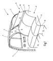
- Fig. 1 illustrates the broken, truncated rear area a car.
- the figure illustrates a Look at the right inside, which is not illustrated left inside is mirror image.
- the Presentation is simplified, for example, body Internal structures, such as stiffeners and fasteners not shown because of their representation for understanding the invention is not required.
- the illustrated body section 1 includes Roof 2, from the side of a B-pillar 3 down to a floor group, not shown leads. A corresponding B-pillar would be on the broken side of the vehicle too think.
- the roof 2 goes at its rear edge in a rear window 4 over. Laterally, the rear window 4 ends at one C-pillar 5, which is located at a distance from the B-pillar 3.
- the C-pillar 5 carries an inner lining 6.
- a rear seat 8 At the height of the rear, right side door 7 is located a rear seat 8, to which a seat 9 and a rear seat back 11 belong.
- the rear seat 9 lies on a base surface 12 leading to the floor assembly heard and trained in the front of the rear seat 9 foot wells 13 are.
- a rear window roller blind 14 On the inside in front of the rear window 4 is located a rear window roller blind 14. From the rear window roller blind 14 is its partially extended roller blind as well as one of the lateral To recognize guide rails 16. The guide rail 16 begins at an existing behind the rear seat back 11 Hat rack 17 and runs next to the side edge of the window. In addition, the hat rack 17 contains a continuous Pull-out slot 18 from which the roller blind 15 runs out.
- winding shaft 19 rotatably mounted on the with an edge of the blind sheet 15 is attached.
- the winding shaft 19 is by means of a schematically indicated spring motor 21 in the sense of winding the roller blind 15 on the winding shaft 19 biased.
- This is a coil spring provided anchored at one end of the body and the other end is set in the winding shaft 19.
- the roller blind 15 has an approximately trapezoidal blank on and is at their remote from the winding shaft 19 Edge provided with a tubular loop 22. Through the tubular loop 22 performs a pull-out profile or bow, in the guide pieces 23 and 24th are mounted telescopically.
- the guide pieces 23 and 24 have a neck portion 25 which has a smaller diameter has as an adjoining guide member 26, which has the shape of a short cylindrical Section has.
- the guide pieces 26 run in the Guide rails 16, next to the two side edges of the Rear window 4 are arranged. The structure of the guide rails 16 is explained below with reference to FIGS. 3 and 4.
- Each of the guide rails 16 includes a guide groove 27, which extends in the direction of the roller blind 15 in a guide slot 28 opens.
- each guide rail 16 is with a Guide tube 29, 30 connected, in which kink-resistant two flexible thrust members 31 and 32 are guided.
- the bendable Thrust members 31 and 32 are so-called Suflex waves. She consist of a cylindrical core, of a helically extending rib is surrounded. To this Way is a kind of flexible racks with all-round teeth receive.
- the guide tubes 29 and 30 connect the guide rails 16 with a gear motor 33.
- the geared motor 33 consists of a permanently excited DC motor 34 and a gear 35 together on the output shaft 36 a spur gear 37 rotatably seated.
- the gear 37 meshes with the two push members 31 and 32 positively. These Thrust members 31 and 32 tangentially to the diametrically opposite sides of the spur gear 37 over and are for this purpose in corresponding holes 38 and 39 guided.
- Thrust members 31, 32 By starting the geared motor 33 are the Thrust members 31, 32 selectively advanced or withdrawn. The movement of the push members 31, 32 follow the guide pieces 23 and 24. These are using the spring motor 21 against the free ends of the thrust members 31, 32nd held adjacent, which are located in the guide grooves 27.
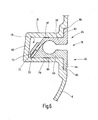
- Fig. 3 shows in cross section the structure of the guide rails 16th
- Fig. 3 is the guide rail 16 of an outer part 41 and a Support member 42 together.
- the outer part 41 consists of a thermoplastic and goes in one piece in the Interior trim 6 of the C-pillar 5 via.
- the outer part 41 includes the undercut guide groove 27, which is about the slot 28 opens to the outside. Seen in cross-section mentally sets the guide groove 27 of a circular Section 43 and a rectangular section 44 together.
- the diameter of the circular portion 43 is adapted to the diameter of the guide pieces 26.
- the outer part 41 shows an outer or Sichseite 45th on, approximately parallel to a rear 46 runs.
- the Outside 45 is through the slot 28 in a section 45 a and a section 45 b divided.
- the outer part 41 forms a the rear 46 projecting wall portion 47, at its free end passes over a wall portion 48, the one Circle section follows.
- the wall section 48 closes again a straight wall section 49 which leads to the wall section 47 is parallel and in the wall section 45 b opens.
- the structure is at the rear 46 free of undercuts, i. the Both wall sections 47 and 49 are from on the outside bounded by two mutually parallel side walls.
- a first hook strip 51 In addition to the wall portion 47 extends parallel to the longitudinal extent of the slot 48 a first hook strip 51, the, together with the wall portion 47 at the inner corner a groove 52 is created. A mirror image of this is one second hook strip 53 provided in addition to the outside of the wall portion 49 is arranged and together with the Outside of the wall portion 49 forms a groove 54.
- the dimensions of the two hook strips 51 and 53 are selected so that the outer part 41 after spraying readily from the complementary mold cavity of the injection mold can be subtracted by the elasticity of the Hook strips 51 and 53 is utilized. That way is the use of complicated tools with moving Cores for creating undercuts in this respect dispensable.
- the wall thickness in the region of the wall section 48, the cylindrical portion 43 of the cross-sectional profile surrounds, in relation to the width of the Slot 28 is chosen so that the finished molded outer part 41 of the mold core for generating the cross section 43rd and the cross-section 44 can be deducted in Direction perpendicular to the plane passing through the outside 45 a and 45 b is formed.
- the outer part 41 is in the region of the guide groove widened until the corresponding part of the mold core can slide out through the slot 28. Due to the inherent elasticity can the outer part 41 then in the original spring back planned form.
- the support member 42 is provided.
- the Support member 42 is disposed on the body, like this one schematically indicated section 55 of the inside of the Body panel reveals.
- the support member 42 sets composed of a mounting plate 56, of the two Lean legs 57 and 58.
- the legs 57 and 58 limit an interior that is suitable to play the Structure to absorb the back contour of the outer part 41 forms in the region of the guide groove 27.
- This U-shaped opening consists of an arcuate Part together, where the wall section 48 abuts, and two parallel surfaces, where the Create outside of the wall sections 47 and 49.
- the free ends of the two legs 57 and 58 are provided with flat hook noses 59 and 61, which are the hook strips 51 and 53 are complementary.
- the support member 52 consists of a relatively solid and relatively inelastic material that is capable the forces that occur in operation, the widening of the slot 28, sufficient resistance opposes.
- the support member 42 consists of an aluminum extruded profile, if applicable, below still according to the desired course, to be bent can.
- a guide rail 16 get over a great length made of plastic, with no moving core is required in the injection molding tool.
- Such Shape would be very difficult to produce and extremely expensive because at a diameter of the nikfömigen part 43 of the guide groove 27 of about 8 mm it is very difficult, this core as a movable core to a length of about 50 cm position correct to hold.
- the guide rail 16 avoids such a movable Core. Rather, the core can be rigidly attached to a bridge be who molds the slot 28.
- Another advantage of the solution according to the invention consists in that the color visible to the viewer the guide rail 16 exactly the color of the inner lining 6 corresponds. No provision needs to be made to hide a shiny aluminum rail, like this is required in the prior art.
- thermoplastic material shows more favorable Sliding properties in connection with the guide body 26. There is no longer a need for the guide body 26 necessarily made of plastic or with - To coat plastic, to favorable sliding properties to get as required when the Guide rail would consist of aluminum profile.
- the plastic surface tends to be due the compliance much less to rattling noises, than a hard metal surface.
- the metal is limited to the support member 42.
- the undeformable support member 42 ensures a long time the dimensional accuracy of the guide groove 27th
- the guide groove 27 the already explained shape in the sense that they are made of a circular section and a rectangular one Section exists, which corresponds to the slot 28.
- the guide rail 16 according to FIG. 4 is in two parts, wherein a first part 63 integral with the portion 45 a and another part 64 integral with the portion 45 b connected is.
- the visible side portion 45 a is part of a flange 65, which extends to the slot 28 and there in one Wall section 66 passes.
- the wall portion 66 a terminates a surface 67 which is at an angle of about 30 to 60 Degree opposite the visible side 45 a runs.
- the flange 45 forms together with the wall portion 66 about a right-angled rail, on its side the wall portion or leg 66 on the outside, from the inner corner away side, as the figure 4 recognize makes part of the wall that forms the circular one Section section 43 corresponds and a wall section, the right-angled cross-sectional profile section 44 limited.
- the wall 67 ends approximately at the height of a plane that Referring to Fig. 4 of the upper boundary wall of the slot 28 corresponds. From this point, the wall or the Leg 66 into a narrow ledge 68 over which, as shown, protrudes beyond a plane through the center of the circular section 43 and the middle of the Slot 28 is defined.
- the other part 64 of the guide rail 16 is integrally Part of the interior trim 6 and shows in Basically a similar complementary shape as the Part 63.
- the visible side section 45 b is followed Leg 69, which is parallel to the leg 66.
- the in the leg 66 facing side of the leg 69 has an outer contour, the outer contour of the leg 66th added to the complete guide groove 67.
- the leg 69 On the opposite side of the slot 68 is the leg 69, which is a bit far above the Slot 28 surmounted, provided with a groove 71 which mounted in the Condition, as shown, the bar 68 receives. Either the bar 68 and the groove 71 extend over the entire length of the guide rail 16.
- Ribs 74 may be provided on tabs 72, which make it possible to locally the wall of the To weld opening 73 with the rib 74.
- This welding can be an ultrasonic welding by there corresponding sonotrodes are pressed, or it exists also the possibility here the parts with each other laser to weld.
- the stabilization carrier 75 is shorter than the Guide rail 16 and has a substantially U-shaped Shape up and out at its free ends pointing hooked noses 76 and 77 provided with hook strips 51 and 53 cooperate, as in a similar way is explained with reference to FIG. 3.
- the slot 28 can not expand, still reduce in width.
- stabilizers 75 can be spaced apart be plugged from each other.
- FIGS. 4 and 5 respectively, FIGS Both parts 63 and 64 in turn virtually undercut.
- the hook strips 51 and 53 have, if they are present, so slight undercuts, that without further the inherent elasticity of these hook strips 51 and 53 would suffice for them from the injection mold to take out without requiring a draggable core.
- the structure shown makes it possible to use a guide rail plastic injection using very inexpensive injection molding tools. The advantages, the with a plastic guide rail were already connected in connection with FIG. 3 explained in detail, so a repetition dispensable here is.
- the guide rails 16 according to FIGS. 3 and 4 were each explained as if they were, at least in sections, Part of the interior trim, for example the C-pillar. It goes without saying, however, that also the guide rails 16 may be formed separately from this and with not shown tabs or other locking members with correspondingly complementary locking members of the Side panel or the body can be connected. The visible side portion 45 B would then be approximately at the End point, at the in the figures shown the arcuate Course begins.
- the tabs for locking the guide rail 16 would, for example, in the case of execution according to Figures 4 and 5 in extension of the slot 28 may be arranged on the leg 69.
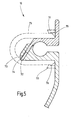
- Fig. 6 shows an embodiment of the guide rail assembly 16, which is basically the execution which Fig. 4 and 5 corresponds. However, here is the Guide rail assembly 16 inserted into a groove 78, the is formed in the side trim part 6. The side panel part 6 is thus integrally over the Groove 78 continues.
- the groove 78 is laterally of two walls 79 and 81 limited.
- the groove 78 is parallelepiped in this area.
- the two side walls 81 and 79 are through a floor 82 integrally connected.
- the guide rail arrangement 16 corresponds, as already mentioned, the guide rail assembly 16 according to FIGS. 4 and 5 and sits down from the two parts 64 and 65 together. They are training the outside of the side panel part short strip-like Flanges 83 and 84, which are in corresponding recesses 85 and 86 of the side trim part 6 flush sunk are.
- creases 87 and 88 are provided, which have a sawtooth-shaped profile and the creases on the inside of the walls 81 and 79 are complementary.
- a window blind for motor vehicles has plastic existing guide rails on.
- the guide rails are specifically designed such that injection molding tools can be used to generate the Guide groove without moving cores get along.
Landscapes
- Engineering & Computer Science (AREA)
- Mechanical Engineering (AREA)
- Window Of Vehicle (AREA)
- Operating, Guiding And Securing Of Roll- Type Closing Members (AREA)
- Support Devices For Sliding Doors (AREA)
- Moulds For Moulding Plastics Or The Like (AREA)
Abstract
Description
Die DE 100 57 759 A1 zeigt ein Heckscheibenrollo für Kraftfahrzeuge. Zu dem Heckscheibenrollo gehört eine unterhalb der Hutablage drehbar gelagerte Wickelwelle, an der mit einer Kante die Rollobahn befestigt ist. Die Rollobahn ist etwa trapezförmig zugeschnitten und mit ihrer anderen, von der Wickelwelle abliegenden Kante an einem Zugstab befestigt. Der Zugstab wird seitlich in zwei Führungsschienen geführt, die an der Innenseite der Heckscheibe aufgeklebt bzw. hinter der C-Säulenverkleidung in der Karosserie verborgen sind. In den Führungsschienen laufen biegeelastische Schubglieder, die ausknicksicher in den Führungsschienen geführt sind.DE 100 57 759 A1 shows a rear window blind for Motor vehicles. To the rear window blind is one below the hat rack rotatably mounted winding shaft on the with an edge of the roller blind is attached. The roller blind is roughly trapezoidal in shape and with its other, attached from the winding shaft edge attached to a pull rod. The tie rod is laterally in two guide rails guided, which glued to the inside of the rear window or hidden behind the C-pillar trim in the body are. In the guide rails flexurally elastic run Thrust members that are kink-proof in the guide rails are guided.
Die Führungsschienen bestehen aus einem Aluminiumstrangpressprofil, das eine durchgehende hinterschnittene Nut enthält. Die Nut setzt sich zusammen aus einem kreisförmigen Querschnittsabschnitt und einem rechteckförmigen, wobei der rechteckförmige schmäler ist als es dem Duchmesser des Kreises entspricht. Der rechteckförmige Abschnitt bildet den Schlitz, über den die Führungsnut nach außen hin offen ist.The guide rails consist of an aluminum extruded profile, the one continuous undercut Groove contains. The groove is composed of a circular Cross-sectional portion and a rectangular, wherein the rectangular is narrower than the diameter of the circle corresponds. The rectangular section forms the slot over which the guide groove outwards is open.
In den Führungsschienen laufen Gleit- oder Führungskörper, die einen Kopf aufweisen, der im Querschnitt an den kreisförmigen Abschnitt des Führungsschienenprofils angepasst ist. Dieser Kopf hat entweder die Gestalt einer Kugel oder eines kurzen zylindrischen Stückes, das so bemessen ist, dass es in den gekrümmten Abschnitten der Führungsschienen nicht klemmt. Der Durchmesser des Halses ist so bemessen, dass er klemmfrei durch den Schlitz der Führungsnut passt.Sliding or guiding bodies run in the guide rails, which have a head which in cross section to the adjusted circular portion of the guide rail profile is. This head is either in the shape of a ball or a short cylindrical piece that is so sized is that it is in the curved sections of the guide rails not stuck. The diameter of the neck is like that Measure that it is free from jamming through the slot of the guide groove fits.
Der Kopf des Führungsteils des Auszugprofils besteht üblicherweise aus einem gespritzten Kunststoffs.The head of the guide part of the pull-out profile consists usually made of a molded plastic.
Es hat sich im Laufe der Zeit herausgestellt, dass die Paarung aus dem Kunststoff und der Aluminiumschiene nicht unter allen Bedingungen klapperfrei ist.It has been proven over time that the Mating of the plastic and the aluminum rail is not rattle-free in all conditions.
Die Reibpaarung aus den Kunststoffführungskörpern und der Aluminiumschiene ist ebenfalls nicht optimal.The friction pairing from the plastic guide bodies and The aluminum rail is also not optimal.
Schließlich bestehen gewisse Schwierigkeiten die Führungsschiene mit der Innenverkleidung zu kombinieren.Finally, there are some difficulties the guide rail to combine with the interior trim.
Ausgehend hiervon ist es Aufgabe der Erfindung eine neue Führungsschienenanordnung zu schaffen, die die Nachteile nach dem Stand der Technik vermeidet.Based on this, it is an object of the invention new guide rail assembly to create the disadvantages avoids the prior art.
Diese Aufgabe wird erfindungsgemäß durch die Führungsschiene
mit den Merkmalen des Anspruches 1 oder 35 gelöst. This object is achieved by the guide rail
solved with the features of
Bei der einen Lösung ist vorgesehen, die Führungsschienenanordnung aus zwei Teilen zusammen zu setzen. Der eine Teil bildet den Außenteil, der aus einem elastisch verformbaren Material hergestellt ist. Der andere Teil dient als Stützteil und besteht aus einem weniger verformbarem Material um auf alle Fälle sicher zu stellen, dass der Außenteil, der die hinterschnittene Führungsnut enthält, stabilisiert wird, damit im Laufe der Zeit sich die Schlitzweite der Führungsnut nicht verändert.In one solution is provided, the guide rail assembly composed of two parts. Of the a part forms the outer part, which is made of an elastic deformable material is made. The other part serves as a support part and consists of a less malleable Material to make sure that the outer part, which contains the undercut guide groove, is stabilized so that over time the Slot width of the guide not changed.
Der wesentliche Vorteil dieser Anordnung besteht unter anderem darin, dass bei einer Reihe von Gestaltungen des Außenteils zur Herstellung keine Spritzwerkzeuge mit einem ziehbaren Kern benötigt werden. Da das Material des Außenteils elastisch verformbar ist, kann das fertig gespritzte Teil von dem Kern, der die hinterschnittene Führungsnut beim Spritzen frei hält, einfach abgezogen werden. Hierdurch verbilligt sich das Herstellungsverfahren erheblich. Insbesondere ist es möglich auf diese Weise einfach das Außenteil einstückig mit einem daran angeformten Abschnitt der Innenverkleidung des Kraftfahrzeuges zu integrieren. Der Stützteil selbst besitzt keine hinterschnittenen Nuten und benötigt so auf keinen Fall irgend welche Spritzgusswerkzeuge mit beweglichen Kernen.The main advantage of this arrangement is below Another is that in a number of designs of the Outer part for making no injection molds with a draggable core needed. Because the material of the outer part is elastically deformable, the finished sprayed Part of the core, the undercut guide groove kept free during spraying, simply peeled off. hereby the manufacturing process is considerably cheaper. In particular, it is possible in this way simply the Outer part in one piece with a molded-on section to integrate the interior trim of the motor vehicle. The support member itself has no undercut grooves and does not need any injection molding tools in any way with moving cores.
Der Außenteil kann eine schmale, längliche Form aufweisen, die im Wesentlichen dem Formverlauf der Führungsnut folgt.The outer part may have a narrow, elongated shape, the substantially the shape of the guide groove follows.
Die Verbindungsmittel zwischen dem Stützteil und dem Außenteil können von Rastmitteln gebildet sein. Diese Rastmittel umfassen beispielsweise einen Haken, der als hintergriffige Leiste ausgeführt sein kann. Komplementäre Verbindungsmittel sind an dem Stützteil vorgesehen. Auch hierbei kann wiederum eine hinterschnittene Leiste verwendet werden. Eine hinterschnittene Leiste stellt bei dem Stützteil kein Problem dar, soweit beispielsweise als Strangpressprofil hergestellt wird, das nachträglich in die gewünschte Form gebogen wird.The connecting means between the support member and the Outer part may be formed by locking means. This locking means include, for example, a hook, which is as behind-grip Bar can be executed. Complementary lanyards are provided on the support part. Also here In turn, an undercut bar can be used. An undercut bar puts at the support part no problem, as far as, for example, as an extruded profile is subsequently produced in the desired Shape is bent.
Das Material des Außenteils ist vorzugsweise aus einer Gruppe von Thermoplasten ausgewählt. Hierdurch wird die gewünschte Nachgiebigkeit erzeugt, wobei die Gefahr einer eventuellen Verformung im Laufe der Zeit durch das Stützteil begegnet wird.The material of the outer part is preferably made of a Group of thermoplastics selected. This will be the desired yield generated, with the risk of possible deformation over time by the support member is encountered.
Der Stützteil weist hierzu einen Bereich auf, der im montierten Zustand die Führungsnut, zumindest abschnittsweise, an den Flanken seitlich stützt. Im einfachsten Falle enthält das Stützteil hierzu eine Nut, die U-förmig gestaltet ist und Parallelflanken aufweist.For this purpose, the support part has an area which in the assembled state the guide groove, at least in sections, supported laterally on the flanks. In the simplest case For this purpose, the support part contains a groove which is U-shaped is and has parallel edges.
Der Stützteil kann aus einem Leichtmetall hergestellt sein.The support member may be made of a light metal be.
Bei der anderen Ausführungsform ist vorgesehen, dass die Führungsschienenanordnung aus einem ersten und einem zweiten Teil besteht, die beide als Formteil hergestellt sind, wobei die Fuge, an denen die beiden Teile miteinander gefügt sind, in Längsrichtung der Führungsnut verlaufen. Dadurch können die beiden Teile, jedes für sich, frei von Hinterschneidungen gehalten sein. Erst nach dem Fügen der beiden Teile entsteht die hinterschnittene Führungsnut für das Rollo. In the other embodiment it is provided that the guide rail assembly of a first and a second part is made, both made as a molded part are, with the fugue, where the two parts together are joined, extend in the longitudinal direction of the guide groove. This allows the two parts, each for themselves, free from Undercut be held. Only after joining the Both parts creates the undercut guide groove for the blind.
Da jedes Teil für sich frei von Hinterschneidungen ist, besteht auch hier wieder die Möglichkeit eines der beiden Teile mit einem Abschnitt der Innenverkleidung, beispielsweise der C-Säule einstückig zu integrieren, d.h. diesen Teil der Führungsschienenanordnung mit dem plattenförmigen Teil der Seitenverkleidung einstückig zu spritzen.Because each part is free from undercuts is again the possibility of one of the two parts with a section of the interior trim, for example integrally integrating the C-pillar, i. this part of the guide rail assembly with the plate-shaped Part of the side panel to inject in one piece.
An beiden Teilen sind Verbindungsmittel vorgesehen um die beiden Teile relativ zueinander zu positionieren.On both parts connecting means are provided to to position the two parts relative to each other.
Die Verbindungsmittel können sich auch über die gesamte Länge der beiden Teile erstrecken. Beispielsweise besteht in diesem Falle eines der Verbindungsmittel in einer Leiste, während das andere Verbindungsmittel eine Nut ist. Um eine Positionierung in Längsrichtung der Führungsnut zu erreichen kann die Leiste Zapfen tragen, die in zusätzliche Öffnung in die Nut eingreifen.The connecting means can also be over the entire Length of the two parts extend. For example consists in this case one of the connecting means in one Strip, while the other connecting means a groove is. To a positioning in the longitudinal direction of the guide To reach the ledge can carry tenons, which in additional Engage opening in the groove.
Um einen günstigen Kräfteverlauf zu erzielen, der keine ungünstige Sprengwirkung auf die beiden Teile ausübt, wenn das Führungsstück des Rollos durch die Führungsnut läuft, ist es von Vorteil, wenn die Leiste unter einem spitzen Winkel zu einer Ebene verläuft, die durch den Schlitz definiert ist und durch den Schlitz hindurch führt.To achieve a favorable flow of forces that no unfavorable explosive effect on the two parts, when the guide piece of the roller blind through the guide groove running, it is beneficial if the bar under one acute angle to a plane passing through the Slot is defined and passes through the slot.
Zusätzlich zu den beiden Teilen, die miteinander verbunden sind, kann noch ein Stützteil vorgesehen sein, das aus einem weniger verformbaren Material besteht und das auf die beiden Teile aufgesetzt wird. Es dient dazu einen Verzug der Kunststoffformteile zu verhindern. Dieser Verzug kann durch Alterungen oder alterungsbedingten Schwund hervorgerufen werden. Die Stützteile stablisieren die Nut und sorgen dafür, dass der Schlitz der Führungsnut über die Länge gesehen eine konstante Weite beibehält.In addition to the two parts connected to each other are still a support member may be provided, the made of a less deformable material and that on the two parts are put on. It serves a delay prevent the plastic moldings. This delay can be caused by aging or age-related wasting become. The support parts stabilize the groove and make sure that the slot of the guide groove over the Length maintained a constant width.
Die beiden Teile können miteinander, zumindest Abschnittsweise stoffschlüssig verbunden sein. Zum stoffschlüssigen Verbinden kommen Laserschweißen, Ultraschallschweißen, Kleben oder sonstige Verbindungstechniken in Frage.The two parts can be together, at least in sections be connected cohesively. For cohesive Joining come laser welding, ultrasonic welding, Gluing or other joining techniques in Question.
Im Übrigen sind Weiterbildungen Gegenstand von Unteransprüchen.For the rest, further developments are the subject of dependent claims.
Nach dem Lesen der Beschreibung wird dem Fachmann klar, dass eine Reihe von Abwandlungen möglich sind.After reading the description will become the skilled person Clear that a number of modifications are possible.
In der Zeichnung sind Ausführungsbeispiele des Gegenstandes der Erfindung dargestellt. Es zeigen:
- Fig. 1
- eine teilweise aufgebrochene Heckpartie eines Kraftfahrzeuges, in einer perspektivischen Darstellung mit Blick gegen die Innenseite der Heckscheibe,
- Fig. 2
- den prinzipiellen Aufbau des Heckscheibenrollos nach Fig. 1,
- Fig. 3
- eine erste Führungsschienenanordnung bestehend aus einem Stützteil und einem Außenteil, in einem Schnitt quer zur Längserstreckung der Führungsnut,
- Fig. 4
- ein zweites Ausführungsbeispiel der erfindungsgemäßen Führungsschienenanordnung aus zwei miteinander gefügten Teilen, die gemeinsam die Führungsnut begrenzen, in einer ersten Höhe geschnitten quer zur Längserstreckung der Führungsnut,
- Fig. 5
- die Führungsschienenanordnung nach Figur 4, geschnitten in einer anderen Höhe, und
- Fig. 6
- eine Ausführungsform einer Führungsschienenanordnung ähnlich der nach Fig. 4, jedoch eingesetzt in eine Nut einer Seitenverkleidung.
- Fig. 1
- a partially broken rear end of a motor vehicle, in a perspective view looking towards the inside of the rear window,
- Fig. 2
- the basic structure of the rear window roller blind of FIG. 1,
- Fig. 3
- a first guide rail arrangement consisting of a support part and an outer part, in a section transverse to the longitudinal extent of the guide groove,
- Fig. 4
- a second embodiment of the guide rail assembly according to the invention of two parts joined together, which together define the guide groove, cut at a first height transverse to the longitudinal extent of the guide groove,
- Fig. 5
- the guide rail assembly of Figure 4, cut at a different height, and
- Fig. 6
- an embodiment of a guide rail assembly similar to that of FIG. 4, but inserted into a groove of a side panel.
Fig. 1 stellt den aufgebrochenen, abgeschnitten Fondbereich eines PKW dar. Die Figur veranschaulicht einen Blick auf die rechte Innenseite, die zu der nicht veranschaulichten linken Innenseite spiegelbildlich ist. Die Darstellung ist vereinfacht, so sind beispielsweise Karosserie Innenstrukturen, wie Versteifungen und Befestigungsmittel nicht gezeigt, da ihre Darstellung für das Verständnis der Erfindung nicht erforderlich ist.Fig. 1 illustrates the broken, truncated rear area a car. The figure illustrates a Look at the right inside, which is not illustrated left inside is mirror image. The Presentation is simplified, for example, body Internal structures, such as stiffeners and fasteners not shown because of their representation for understanding the invention is not required.
Der veranschaulichte Karosserieabschnitt 1 weist ein
Dach 2 auf, von dem seitlich eine B-Säule 3 nach unten zu
einer nicht gezeigten Bodengruppe führt. Eine entsprechende
B-Säule wäre auf der weggebrochenen Seite des Fahrzeugs zu
denken. Das Dach 2 geht an seiner Hinterkante in ein Heckfenster
4 über. Seitlich endet das Heckfenster 4 an einer
C-Säule 5, die sich im Abstand zu der B-Säule 3 befindet.
Die C-Säule 5 trägt eine Innenverkleidung 6.The illustrated body section 1 includes
Zwischen der B-Säule 3 und der C-Säule 5 ist an der B-Säule
3 eine hintere, reche Seitentür 7 in der bekannten
Weise anscharniert. Between the B-
Auf der Höhe der hinteren, rechten Seitentür 7 befindet
sich eine Rücksitzbank 8, zu der eine Sitzfläche 9 sowie
eine Rücksitzlehne 11 gehören. Die Rücksitzfläche 9
liegt auf einer Sockelfläche 12, die zu der Bodengruppe
gehört und in der vor der Rücksitzfläche 9 Fußräume 13 ausgebildet
sind.At the height of the rear, right side door 7 is located
a
Auf der Innenseite vor dem Heckfenster 4 befindet sich
ein Heckscheibenrollo 14. Von dem Heckscheibenrollo 14 ist
dessen teilweise ausgezogene Rollobahn sowie eine der seitlichen
Führungsschienen 16 zu erkennen. Die Führungsschiene
16 beginnt an einer hinter der Rücksitzlehne 11 vorhandenen
Hutablage 17 und verläuft neben der seitlichen Fensterkante.
Außerdem enthält die Hutablage 17 einen durchgehendenden
Auszugsschlitz 18, aus dem die Rollobahn 15 herausläuft.On the inside in front of the rear window 4 is located
a rear
Der prinzipelle Aufbau des Heckscheibenrollos 14 ergibt
sich aus Fig. 2.The basic structure of the rear
Unterhalb der Hutablage 17 ist, wie sich aus Fig. 2
ergibt, eine Wickelwelle 19 drehbar gelagert, an der mit
einer Kante die Rollobahn 15 befestigt ist. Die Wickelwelle
19 ist mit Hilfe eines schematisch angedeuteten Federmotors
21 im Sinne des Aufwickelns der Rollobahn 15 auf die Wickelwelle
19 vorgespannt. Hierzu ist eine Schraubenfeder
vorgesehen, die einends karosseriefest verankert und andernends
in der Wickelwelle 19 festgelegt ist.Below the
Die Rollobahn 15 weist einen etwa trapezförmigen Zuschnitt
auf und ist an ihrer von der Wickelwelle 19 abliegenden
Kante mit einer schlauchförmigen Schlaufe 22 versehen.
Durch die schlauchförmige Schlaufe 22 führt ein Auszugsprofil
oder Spriegel, in dem Führungsstücke 23 und 24
teleskopartig gelagert sind. Die Führungsstücke 23 und 24
weisen einen Halsteil 25 auf, der einen kleineren Durchmesser
aufweist als ein sich daran anschließendes Führungsglied
26, das die Gestalt eines kurzen zylinderförmigen
Abschnitts aufweist. Die Führungsstücke 26 laufen in den
Führungsschienen 16, die neben den beiden Seitenkanten des
Heckfensters 4 angeordnet sind. Der Aufbau der Führungsschienen
16 ist weiter unten anhand der Fig. 3 und 4 erläutert.The
Jede der Führungsschienen 16 enthält eine Führungsnut
27, die sich in Richtung auf die Rollobahn 15 in einem Führungsschlitz
28 öffnet.Each of the guide rails 16 includes a
Das untere Ende jeder Führungsschiene 16 ist mit einem
Führungsrohr 29, 30 verbunden, in denen knicksteif zwei
biegsame Schubglieder 31 und 32 geführt sind. Die biegsamen
Schubglieder 31 und 32 sind sogenannte Suflexwellen. Sie
bestehen aus einem zylinderförmigen Kern, der von einer
schraubenförmig verlaufenden Rippe umgeben ist. Auf diese
Weise wird eine Art flexibler Zahnstangen mit Rundumverzahnung
erhalten.The lower end of each
Die Führungsrohre 29 und 30 verbinden die Führungsschienen
16 mit einem Getriebemotor 33. Der Getriebemotor
33 setzt sich aus einem permanent erregten Gleichstrommotor
34 und einem Getriebe 35 zusammen auf dessen Ausgangswelle
36 ein Stirnzahnrad 37 drehfest sitzt. Das Zahnrad 37 kämmt
mit den beiden Schubgliedern 31 und 32 formschlüssig. Diese
Schubglieder 31 und 32 laufen tangential an die an diametral
gegenüberliegenden Seiten an dem Stirnzahnrad 37 vorbei
und sind hierzu in entsprechenden Bohrungen 38 und 39
geführt.The
Durch Ingangsetzen des Getriebemotors 33 werden die
Schubglieder 31, 32 wahlweise vorgeschoben oder zurückgezogen.
Der Bewegung der Schubglieder 31, 32 folgen die Führungsstücke
23 und 24. Diese werden mit Hilfe des Federmotors
21 gegen die freien Enden der Schubglieder 31, 32
anliegend gehalten, die sich in den Führungsnuten 27 befinden.By starting the geared
Fig. 3 zeigt im Querschnitt den Aufbau der Führungsschienen 16.Fig. 3 shows in cross section the structure of the guide rails 16th
Entsprechend dem Querschnitt nach Fig. 3 setzt sich
die Führungsschiene 16 aus einem Außenteil 41 und einen
Stützteil 42 zusammen. Das Außenteil 41 besteht aus einem
thermoplastischen Kunststoff und geht einstückig in die
Innenverkleidung 6 der C-Säule 5 über. Das Außenteil 41
enthält die hinterschnittene Führungsnut 27, die sich über
den Schlitz 28 nach außen öffnet. Im Querschnitt gesehen
setzt sich die Führungnut 27 gedanklich aus einem kreisförmigen
Abschnitt 43 und einem rechteckigen Abschnitt 44 zusammen.
Der Durchmesser des kreisförmigen Abschnitts 43 ist
an den Durchmesser der Führungstücke 26 angepasst.According to the cross section of Fig. 3 is
the
Das Außenteil 41 zeigt eine Außen- oder Sichseite 45
auf, zu der etwa parallel eine Rückseite 46 verläuft. Die
Außenseite 45 wird durch den Schlitz 28 in einen Abschnitt
45 a und einen Abschnitt 45 b aufgeteilt.The
Neben dem Schlitz 28 bildet das Außenteil 41 einen aus
der Rückseite 46 vorstehenden Wandabschnitt 47, der an seinem
freien Ende einen Wandbereich 48 übergeht, der einem
Kreisabschnitt folgt. An den Wandabschnitt 48 schließt sich
wieder ein gerader Wandabschnitt 49 an, der zu dem Wandabschnitt
47 parallel ist und in den Wandabschnitt 45 b
einmündet.In addition to the
Wie der Querschnitt erkennen lässt, ist die Struktur
an der Rückseite 46 frei von Hinterschneidungen, d.h. die
beiden Wandabschnitte 47 und 49 werden von an der Außenseite
von zwei zueinander parallelen Seitenwänden begrenzt.As the cross section reveals, the structure is
at the rear 46 free of undercuts, i. the
Both
Neben dem Wandabschnitt 47 verläuft parallel zur Längserstreckung
des Schlitzes 48 eine erste Hakenleiste 51,
die, zusammen mit dem Wandabschnitt 47 an der Innenecke
eine Nut 52 entstehen lässt. Spiegelbildlich dazu ist eine
zweiten Hakenleiste 53 vorgesehen, die neben der Außenseite
des Wandabschnitts 49 angeordnet ist und zusammen mit der
Außenseite des Wandabschnitts 49 eine Nut 54 bildet.In addition to the
Die Dimensionierungen der beiden Hakenleisten 51 und
53 sind so gewählt, dass das Außenteil 41 nach dem Spritzen
ohne weiteres von dem komplementären Formnest der Spritzgussform
abgezogen werden kann, indem die Elastizität der
Hakenleisten 51 und 53 ausgenutzt wird. Auf diese Weise ist
die Verwendung von komplizierten Werkzeugen mit beweglichen
Kernen zum Erzeugen von Hinterschneidungen insoweit entbehrlich.The dimensions of the two
Außerdem ist die Wandstärke im Bereich des Wandabschnitts
48, der den zylindrischen Bereich 43 des Querschnittsprofils
umgibt, in Relation zu der Weite des
Schlitzes 28 so gewählt, dass das fertig gespritzte Außenteil
41 von dem Formkern zum Erzeugen des Querschnitts 43
und des Querschnitts 44 abgezogen werden kann, und zwar in
Richtung senkrecht zu der Ebene, die durch die Außenseite
45 a bzw. 45 b gebildet ist. Beim Abziehen von dem Spritzgusswerkzeug
wird das Außenteil 41 im Bereich der Führungsnut
aufgeweitet, bis der entsprechende Teil des Formkerns
durch den Schlitz 28 herausgleiten kann. Aufgrund der Eigenelastizität
kann das Außenteil 41 anschließend in die ursprünglich
geplante Gestalt zurückfedern.In addition, the wall thickness in the region of the
Da eine solche Struktur für sich genommen unter Umständen
zu nachgiebig wäre, um einwandfrei die Führungsglieder
26 zu führen, ohne dass diese aus der Führungsnut
27 freikommen könnten, ist das Stützteil 42 vorgesehen. Das
Stützteil 42 ist karosseriefest angeordnet, wie dies eine
schematisch angedeuteter Abschnitt 55 der Innenseite des
Karosseriebleches erkennen lässt. Das Stützteil 42 setzt
sich aus einer Befestigungsplatte 56 zusammen, von der zwei
Schenkel 57 und 58 aufragen. Die Schenkel 57 und 58 begrenzen
einen Innenraum, der dazu geeignet ist, spielfrei die
Struktur aufzunehmen, die die rückseitige Kontur des Außenteils
41 im Bereich der Führungsnut 27 bildet. Im Einzelnen
setzt sich diese U-förmige Öffnung aus einem bogenförmigen
Teil zusammen, an dem sich der Wandabschnitt 48 anlegt,
sowie zwei zueinander parallelen Flächen, an denen sich die
Außenseiten der Wandabschnitte 47 und 49 anlegen.Because such a structure in itself may under circumstances
would be too forgiving to properly guide
Die freien Enden der beiden Schenkel 57 und 58 sind
mit flachen Hakennasen 59 und 61 versehen, die zu den Hakenleisten
51 und 53 komplementär sind.The free ends of the two
Das Stützteil 52 besteht aus einem relativ festen und
verhältnismäßig unelastischem Material, das in der Lage ist
den in Betrieb auftretenden Kräften, die eine Aufweitung
des Schlitzes 28 bewirken wollen, hinreichenden Widerstand
entgegensetzt.The
Beispielsweise besteht das Stützteil 42 aus einem Aluminiumstrangpressprofil,
das gegebenenfalls nachfolgend
noch entsprechend dem gewünschten Verlauf, gebogen werden
kann.For example, the
Im montierten Zustand greifen die beiden freien Schenkel
57 und 58 in die Nuten 52 und 54 ein und werden dort,
wie gezeigt, verrastet. Hierdurch wird gleichzeitig eine
Verankerung der Innenverkleidung 6 im Bereich der Führungsschiene
16 erreicht.When assembled, the two
Aufgrund der erfindungsgemäßen Lösung wird eine Führungsschiene
16 erhalten, die sich über eine große Länge
aus Kunststoff fertigen lässt, wobei kein beweglicher Kern
in dem Spritzgusswerkzeug erforderlich ist. Eine solche
Form wäre sehr schwer herzustellen und extrem teuer, denn
bei einem Durchmesser des kreisfömigen Teils 43 der Führungsnut
27 von ca. 8 mm ist es nur sehr schwer möglich,
diesen Kern als beweglichen Kern auf eine Länge von ca. 50
cm positionsrichtig zu halten. Der erfindungsgemäße Aufbau
der Führungsschiene 16 vermeidet einen solchen beweglichen
Kern. Vielmehr kann der Kern starr an einem Steg befestigt
werden, der den Schlitz 28 abformt.Due to the solution according to the invention is a
Ein weiterer Vorteil der erfindungsgemäßen Lösung besteht
darin, dass die für den Betrachter sichtbare Farbe
der Führungsschiene 16 exakt der Farbe der Innenverkleidung
6 entspricht. Es müssen keine Vorkehrungen getroffen werden,
um eine glänzende Aluminiumschiene zu verbergen, wie
diese beim Stand der Technik erforderlich ist. Another advantage of the solution according to the invention consists
in that the color visible to the viewer
the
Ferner zeigt das thermoplastische Material günstigere
Gleiteigenschaften in Verbindung mit dem Führungskörper 26.
Es besteht keine Notwendigkeit mehr den Führungskörper 26
unbedingt aus Kunststoff herstellen zu müssen oder mit
- Kunststoff beschichten zu müssen, um günstige Gleiteigenschaften
zu erhalten, wie dies erforderlich ist, wenn die
Führungsschiene aus Aluminiumprofil bestehen würde.Furthermore, the thermoplastic material shows more favorable
Sliding properties in connection with the
Schließlich neigt die Kunststoffoberfläche aufgrund der Nachgiebigkeit weit weniger zu Klappergeräuschen, als eine harte Metalloberfläche.Finally, the plastic surface tends to be due the compliance much less to rattling noises, than a hard metal surface.
Das Metall beschränkt sich auf den Stützteil 42. Der
unverformbare Stützteil 42 gewährleistet über lange Zeit
die Formtreue der Führungsnut 27.The metal is limited to the
In den Fig. 4 und 5 ist ein weiteres Ausführungsbeispiel
einer aus Kunststoff bestehenden Führungsschiene 16
gezeigt. Soweit an diesem Ausführungsbeispiel Strukturelemente
wiederkehren, die mit Strukturelementen identisch
oder gleichwertig sind, wie sie bereits im Zusammenhang mit
Figur 3 erläutert wurden, so wird hierfür dasselbe Bezugszeichen
verwendet ohne eine weitere ausführliche Erläuterung
zu geben.4 and 5 is another embodiment
a
Wie die Figuren erkennen lassen, weist die Führungsnut
27 die bereits erläuterte Gestalt auf in dem Sinne, dass
sie aus einem kreisförmigen Abschnitt und einem rechteckförmigen
Abschnitt besteht, der dem Schlitz 28 entspricht.As the figures show, the
Die Führungsschiene 16 gemäß Fig. 4 ist zweiteilig,
wobei ein erstes Teil 63 einstückig mit dem Abschnitt 45 a
und ein anderes Teil 64 einstückig mit dem Abschnitt 45 b
verbunden ist.The
Der Sichtseitenabschnitt 45 a ist Teil eines Flansches
65, der bis zu dem Schlitz 28 reicht und dort in einen
Wandabschnitt 66 übergeht. Der Wandabschnitt 66 a endet an
einer Fläche 67, die unter einem Winkel von ca. 30 bis 60
Grad gegenüber der Sichtseite 45 a verläuft.The
Der Flansch 45 bildet zusammen mit dem Wandabschnitt
66 etwa eine rechtwinklige Profilschiene, die auf ihre Seite
des Wandabschnittes oder Schenkels 66 auf dessen außen,
von der Innenecke weg zeigenden Seite, wie die Figur 4 erkennen
lässt, einen Teil der Wand bildet, die dem kreisförmigen
Querschnittsabschnitt 43 entspricht sowie einen Wandabschnitt,
der dem rechtseckigen Querschnittsprofilabschnitt
44 begrenzt.The flange 45 forms together with the
Die Wand 67 endet etwa auf der Höhe einer Ebene, die
bezogen auf Fig. 4 der oberen Begrenzungswand des Schlitzes
28 entspricht. Ab dieser Stelle geht die Wand oder der
Schenkel 66 in eine schmale Leiste 68 über die, wie gezeigt,
über eine Ebene hinausragt, die durch den Mittelpunkt
des kreisförmigen Abschnittes 43 und die Mitte des
Schlitzes 28 definiert ist.The
Die Übergangsstelle zwischen der Wand 67 zu der Leiste
68, die an der Außenseite im Übrigen glatt ist, liegt, wenn
man den kreisförmigen Abschnitt 43 als Uhr auffasst, zwischen
10 Uhr und 11 Uhr.The transition point between the
Der andere Teil 64 der Führungsschiene 16 ist einstückiger
Bestandteil der Innenverkleidung 6 und zeigt im
Grunde genommen eine Ähnliche komplementäre Gestalt wie der
Teil 63. An den Sichtseitenabschnitt 45 b schließt sich ein
Schenkel 69 an, der zu dem Schenkel 66 parallel liegt. Die
in dem Schenkel 66 zugekehrte Seite des Schenkels 69 weist
eine Außenkontur auf, die die Außenkontur des Schenkels 66
zu der vollständigen Führungsnut 67 ergänzt.The
Auf der dem Schlitz 68 gegenüberliegenden Seite ist
der Schenkel 69, der ein Stück weit nach oben über den
Schlitz 28 überragt, mit einer Nut 71 versehen, die im montierten
Zustand, wie gezeigt, die Leiste 68 aufnimmt. Sowohl
die Leiste 68 als auch die Nut 71 erstrecken sich über
die gesamte Länge der Führungsschiene 16.On the opposite side of the
Um in Längsrichtung der Führungsschiene 16 die beiden
Teile 63 und 64 positionsrichtig zu halten, trägt die Leiste
68, wie Figur 5 zeigt, in Abständen von ca. 5 cm bis 10
cm Laschen 72. Diese Laschen 72 stecken im montierten Zustand
in rechteckförmigen Öffnungen 73, die im Grund der
Nut 71 in deren Verlängerung angebracht sind.In the longitudinal direction of the
Auf den Laschen 72 können Rippen 74 vorgesehen sein,
die es ermöglichen, dort lokal die betreffende Wand der
Öffnung 73 mit der Rippe 74 zu verschweißen. Dieses Verschweißen
kann ein Ultraschallschweißen sein, indem dort
entsprechende Sonotroden aufgedrückt werden, oder es besteht
auch die Möglichkeit hier die Teile miteinander Laser
zu schweißen.
Sollte die Gefahr bestehen, dass die aus Thermoplast
bestehenden Teile 63 und 64 langfristig nicht hinreichend
formstabil sind, was zu einem Ändern der Weite des Spaltes
28 führen könnte, kann zusätzlich ein Stabilierungsträger
verwendet werden, wie er bei 75 in Fig. 5 gestrichelt angedeutet
ist. Der Stabilisierungsträger 75 ist kürzer als die
Führungsschiene 16 und weist im Wesentlichen eine U-förmige
Gestalt auf und ist an seinen freien Enden mit nach außen
weisenden Hakennasen 76 und 77 versehen, die mit Hakenleisten
51 und 53 zusammenwirken, wie dies in ähnlicher Weise
anhand von Fig. 3 erläutert ist.If there is a risk that the thermoplastic
existing
Da das Stabilisierungsteil 75 gleichzeitig mit der
Innenseite seiner Schenkel an der Außenseite der Schenkel
66 und 69 anliegt, kann sich der Schlitz 28 weder erweitern,
noch in der Breite verringern.Since the stabilizing
Mehrere solche Stabilisierungsträger 75 können im Abstand
voneinander aufgesteckt sein.Several
Wie die Fig. 4 bzw. Fig. 5 erkennen lässt, sind die
beiden Teile 63 und 64 wiederum praktisch hinterschneidungsfrei.
Die Hakenleisten 51 und 53 weisen, wenn
sie vorhanden sind, so geringfügig Hinterschneidungen auf,
dass ohne weiteres die Eigenelastizität dieser Hakenleisten
51 und 53 ausreichen würde um sie aus dem Spritzwerkzeug
herauszunehmen, ohne einen ziehbaren Kern zu erfordern. Die
gezeigte Struktur ermöglicht es wiederum, eine Führungsschiene
aus Kunststoff zu spritzen unter Verwendung von
sehr kostengünstigen Spritzgusswerkzeugen. Die Vorteile,
die mit einer aus Kunststoff bestehenden Führungsschiene
verbunden sind, wurden bereits im Zusammenhang mit Fig. 3
ausführlich erläutert, so dass eine Wiederholung hier entbehrlich
ist.As can be seen in FIGS. 4 and 5, respectively, FIGS
Both
Die Führungsschienen 16 nach den Fig. 3 und Fig. 4
wurden jeweils so erläutert, als seien sie, zumindest abschnittsweise,
Teil der Innenverkleidung, beispielsweise
der C-Säule. Es versteht sich jedoch, dass auch die Führungsschienen
16 hiervon getrennt ausgebildet sein können
und mit nicht weiter gezeigten Laschen oder sonstigen Rastgliedern
mit entsprechend komplementären Rastgliedern der
Seitenverkleidung oder der Karosserie verbunden werden können.
Der Sichtseitenabschnitt 45 B würde dann etwa an der
Stelle enden, an der in den gezeigten Figuren der bogenförmige
Verlauf beginnt. Die Laschen zum verrasten der Führungsschiene
16 würden beispielsweise im Falle der Ausführung
nach den Figuren 4 und 5 in Verlängerung des Schlitzes
28 auf dem Schenkel 69 angeordnet sein.The guide rails 16 according to FIGS. 3 and 4
were each explained as if they were, at least in sections,
Part of the interior trim, for example
the C-pillar. It goes without saying, however, that also the guide rails
16 may be formed separately from this
and with not shown tabs or other locking members
with correspondingly complementary locking members of the
Side panel or the body can be connected.
The visible side portion 45 B would then be approximately at the
End point, at the in the figures shown the arcuate
Course begins. The tabs for locking the
Fig. 6 zeigt eine Ausführungsform der Führungsschienenanordnung
16, die im Grunde genommen der Ausführung nach
denen Fig. 4 und 5 entspricht. Allerdings ist hierbei die
Führungsschienenanordnung 16 in eine Nut 78 eingesetzt, die
in dem Seitenverkleidungsteil 6 ausgebildet ist. Das Seitenverkleidungsteil
6 setzt sich somit einstückig über die
Nut 78 hinaus fort.Fig. 6 shows an embodiment of the
Die Nut 78 wird seitlich von zwei Wänden 79 und 81
begrenzt. Die Nut 78 ist in diesem Bereich parallelflankig.
Die beiden Seitenwände 81 und 79 werden durch einen Boden
82 einstückig miteinander verbunden. Die Führungsschienenanordnung
16 entspricht, wie bereits erwähnt, der Führungsschienenanordnung
16 nach den Fig. 4 und 5 und setzt sich
aus den beiden Teilen 64 und 65 zusammen. Sie bilden auf
der Außenseite des Seitenverkleidungsteiles kurze leistenartige
Flansche 83 und 84, die in entsprechenden Vertiefungen
85 und 86 des Seitenverkleidungsteils 6 bündig versenkt
sind.The
Um die Führungsschienenanordnung 16 in der Nut 78
formschlüssig zu halten, sind auf der Außenseite des Schenkels
66 und auf der Außenseite des Schenkels 69 Rillungen
87 und 88 vorgesehen, die ein sägezahnförmiges Profil aufweisen
und die zu Rillungen auf der Innenseite der Wände 81
und 79 komplementär sind.To the
Ein Fensterrollo für Kraftfahrzeuge weist aus Kunststoff bestehende Führungsschienen auf. Die Führungsschienen sind in spezieller Weise derart gestaltet, dass Spritzgusswerkzeuge verwendet werden können, die zum Erzeugen der Führungsnut ohne bewegliche Kerne auskommen.A window blind for motor vehicles has plastic existing guide rails on. The guide rails are specifically designed such that injection molding tools can be used to generate the Guide groove without moving cores get along.
Claims (37)
mit einem Außenteil (41), das als Spritzgussteil aus elastisch verformbaren Material hergestellt ist, das erste Verbindungsmittel (51,53) aufweist und das eine hinterschnittene Führungsnut (27) enthält, die zumindest über einen Teil der Länge des Außenteils (41) durchläuft, und
mit einem Stützteil (42), das aus einem weniger verformbaren Material als das Außenteil (41) hergestellt ist und zweite Verbindungsmittel (59,61) aufweist, die mit den ersten Verbindungsmitteln (51,53) des Außenteils (41) verbindbar sind.Guide rail assembly (16) for blinds (14) and the like in motor vehicles,
an outer part (41) made of an elastically deformable material as an injection molded part, which has first connecting means (51, 53) and which contains an undercut guide groove (27) which runs through at least part of the length of the outer part (41), and
a support member (42) made of a less deformable material than the outer member (41) and having second connecting means (59, 61) connectable to the first connecting means (51, 53) of the outer member (41).
mit einem ersten Teil (63), das als Formteil hergestellt ist, das erste Verbindungsmittel (68) aufweist und das einen im Wesentlichen hinterschneidungsfreien Abschnitt einer Führungsnut (27) enthält, der zumindest über einen Teil der Länge Führungsschienenanordnung (16) durchläuft,
mit einem zweiten Teil (64), das als Formteil hergestellt ist, das zweite Verbindungsmittel (71) aufweist und das einen im Wesentlichen hinterschneidungsfreien Längsabschnitt einer Führungsnut (27) enthält, der zumindest über einen Teil der Länge Führungsschienenanordnung (16) durchläuft und mit dem Längsabschnitt des ersten Teils (63) zusammen eine hinterschnittige Führungsnut (27) ergibt,
wobei die beiden Verbindungsmittel (68,71) miteinander verbindbar sind um die beiden Teile (63,64) relativ zu einander zu positionieren.Guide rail assembly (16) for blinds (14) and the like in motor vehicles,
a first part (63), which is produced as a molded part, which has first connecting means (68) and which contains a substantially undercut-free section of a guide groove (27), which passes through guide rail arrangement (16) over at least part of the length,
a second part (64), which is produced as a molded part, which has a second connecting means (71) and which contains a substantially undercut-free longitudinal section of a guide groove (27) which runs through at least part of the length guide rail arrangement (16) and with the Longitudinal portion of the first part (63) together gives an undercut guide groove (27),
wherein the two connecting means (68,71) are connectable to each other to position the two parts (63,64) relative to each other.
mit einer drehbar gelagerten Rollowelle (19),
mit einer Rollobahn (15), die mit einer Kante an der Rollowelle (15) befestigt ist und die eine von der Rollowelle (15) abliegende Kante (22) aufweist,
mit einem Spriegel (23,24), der mit der Rollobahn (15) an einer von der Rollowelle (19) abliegenden Stelle verbunden ist, und
mit wenigstens einer Führungsschiene (16), in der mit einem Ende der Spriegel (23,24) geführt ist und die aufweist:
with a rotatably mounted roller shaft (19),
with a roller blind (15), which is fastened with one edge to the roller shaft (15) and which has an edge (22) remote from the roller shaft (15),
with a bow (23,24) which is connected to the roller blind (15) at a location remote from the roller blind shaft (19), and
with at least one guide rail (16) in which the bow (23, 24) is guided at one end and has:
mit einer drehbar gelagerten Rollowelle (19),
mit einer Rollobahn (15), die mit einer Kante an der Rollowelle (19) befestigt ist und die eine von der Rollowelle (19) abliegende Kante (22) aufweist,
mit einem Spriegel (23,24), der mit der Rollobahn (15) an einer von der Rollowelle (19) abliegenden Stelle verbunden ist, und
mit wenigstens einer Führungsschiene (16), in der mit einem Ende der Spriegel (23,24) geführt ist und die aufweist:
with a rotatably mounted roller shaft (19),
with a roller blind (15) which is fastened with one edge to the roller shaft (19) and which has an edge (22) remote from the roller shaft (19),
with a bow (23,24) which is connected to the roller blind (15) at a location remote from the roller blind shaft (19), and
with at least one guide rail (16) in which the bow (23, 24) is guided at one end and has:
Priority Applications (1)
| Application Number | Priority Date | Filing Date | Title |
|---|---|---|---|
| EP11159045A EP2338714B1 (en) | 2003-08-28 | 2004-07-30 | Moulded plastic guide rail |
Applications Claiming Priority (3)
| Application Number | Priority Date | Filing Date | Title |
|---|---|---|---|
| DE10362017A DE10362017B4 (en) | 2003-08-28 | 2003-08-28 | Molded plastic guide rail and a window blind for motor vehicles |
| DE10339583 | 2003-08-28 | ||
| DE10339583A DE10339583B4 (en) | 2003-08-28 | 2003-08-28 | Plastic injection molded guide rail |
Related Child Applications (2)
| Application Number | Title | Priority Date | Filing Date |
|---|---|---|---|
| EP11159045A Division EP2338714B1 (en) | 2003-08-28 | 2004-07-30 | Moulded plastic guide rail |
| EP11159045.1 Division-Into | 2011-03-21 |
Publications (3)
| Publication Number | Publication Date |
|---|---|
| EP1510383A2 true EP1510383A2 (en) | 2005-03-02 |
| EP1510383A3 EP1510383A3 (en) | 2008-05-07 |
| EP1510383B1 EP1510383B1 (en) | 2011-11-30 |
Family
ID=49000625
Family Applications (2)
| Application Number | Title | Priority Date | Filing Date |
|---|---|---|---|
| EP11159045A Expired - Lifetime EP2338714B1 (en) | 2003-08-28 | 2004-07-30 | Moulded plastic guide rail |
| EP04018091A Expired - Lifetime EP1510383B1 (en) | 2003-08-28 | 2004-07-30 | Moulded plastic guide rail |
Family Applications Before (1)
| Application Number | Title | Priority Date | Filing Date |
|---|---|---|---|
| EP11159045A Expired - Lifetime EP2338714B1 (en) | 2003-08-28 | 2004-07-30 | Moulded plastic guide rail |
Country Status (7)
| Country | Link |
|---|---|
| US (1) | US7188659B2 (en) |
| EP (2) | EP2338714B1 (en) |
| JP (1) | JP4166737B2 (en) |
| KR (1) | KR100633277B1 (en) |
| CN (4) | CN101173595B (en) |
| AT (1) | ATE535409T1 (en) |
| DE (2) | DE10339583B4 (en) |
Cited By (1)
| Publication number | Priority date | Publication date | Assignee | Title |
|---|---|---|---|---|
| EP3892809A1 (en) | 2020-04-08 | 2021-10-13 | Ensinger GmbH | Method for producing a composite profile |
Families Citing this family (27)
| Publication number | Priority date | Publication date | Assignee | Title |
|---|---|---|---|---|
| DE10351040B3 (en) * | 2003-10-31 | 2005-05-25 | Bos Gmbh & Co. Kg | Window roller blind for motor vehicles and side paneling with integrated guide rail |
| DE102004033982A1 (en) * | 2004-07-14 | 2006-02-02 | Arvinmeritor Gmbh | Guide rail for a roller blind of a sunroof system |
| DE102005029559B4 (en) * | 2005-06-23 | 2007-05-03 | Bos Gmbh & Co. Kg | Rear window blind with complete slot cover through the pull-out profile |
| DE102005030707A1 (en) * | 2005-06-29 | 2007-01-04 | Bos Gmbh & Co. Kg | Window roller blind for motor vehicles with positive stop on the actuator |
| US7413000B2 (en) * | 2005-09-14 | 2008-08-19 | Macauto Industrial Co., Ltd. | Sun screen device |
| DE102005052618A1 (en) * | 2005-11-02 | 2007-05-03 | Bos Gmbh & Co. Kg | Rear window curtain without residuary gap for motor vehicles to reduce heating up on the inside has contour plate, fitted on pull out rail, which runs in such a manner that in functional position almost no residuary gap remains |
| DE102006017883B4 (en) * | 2006-04-13 | 2014-11-06 | Fkt Gmbh | Rear window shade |
| JP4247753B2 (en) * | 2006-08-10 | 2009-04-02 | トヨタ紡織株式会社 | Sunshade equipment |
| DE102007010825A1 (en) * | 2006-12-21 | 2008-06-26 | Wilhelm Karmann Gmbh | Plastic pane attaching method for motor vehicle i.e. cabriolet vehicle, involves connecting plastic pane with folding top cover in edge area by using laser device during laser welding process, where device is arranged opposite to cover |
| DE202007016319U1 (en) * | 2007-07-11 | 2008-02-07 | Bos Gmbh & Co. Kg | Side guide for shading and shading for motor vehicles |
| CN101626672A (en) * | 2008-07-11 | 2010-01-13 | 深圳富泰宏精密工业有限公司 | Slip cover mechanism |
| FR2953768B1 (en) * | 2009-12-15 | 2012-11-23 | Acs France Sas | OCCULTATION DEVICE, VEHICLE AND METHOD OF MANUFACTURING THE SAME |
| US20120175066A1 (en) * | 2011-01-06 | 2012-07-12 | Macauto Industrial Co., Ltd. | Track rail for a sunshade device |
| TW201238797A (en) * | 2011-03-24 | 2012-10-01 | Macauto Ind Co Ltd | Side strip device of sunshade |
| US8540008B2 (en) * | 2012-02-14 | 2013-09-24 | Ing-Wen Chen | Lift guiding system for a car curtain |
| TW201515613A (en) | 2013-10-30 | 2015-05-01 | Macauto Ind Co Ltd | Molded guide rail |
| JP6159230B2 (en) * | 2013-11-06 | 2017-07-05 | 林テレンプ株式会社 | Winding device |
| US20150144278A1 (en) * | 2013-11-28 | 2015-05-28 | Macauto Industrial Co., Ltd. | Molded Guide Rail |
| CN103624933B (en) * | 2013-12-13 | 2016-01-06 | 宁波润佳汽车安全系统有限公司 | A kind of inlaid piece of mould |
| TWM492363U (en) * | 2014-04-15 | 2014-12-21 | Yin-Wen Chen | Guide rail structure of automobile sunshade curtain |
| EP2987667B1 (en) | 2014-08-18 | 2019-10-09 | Inalfa Roof Systems Group B.V. | Guide and sunshade assembly provided therewith |
| EP2987668B1 (en) | 2014-08-18 | 2019-04-24 | Inalfa Roof Systems Group B.V. | Sunshade assembly |
| DE102017103175A1 (en) | 2017-02-16 | 2018-08-16 | Webasto SE | Retaining arrangement for a blind for a vehicle roof, roller blind system and method for producing a holding arrangement for a roller blind |
| CN106945493B (en) * | 2017-03-14 | 2019-10-18 | 福耀玻璃工业集团股份有限公司 | A kind of hemming assembly of glass for vehicle window |
| CN111577761A (en) * | 2019-02-19 | 2020-08-25 | 北自所(北京)科技发展有限公司 | Aluminum profile guide rail and guide rail moving mechanism comprising same |
| CN112440697B (en) | 2019-08-27 | 2023-11-24 | 英纳法天窗系统集团有限公司 | Sunshade system and method for manufacturing components thereof |
| CN114347389B (en) * | 2021-12-31 | 2023-08-11 | 昆山市鸿毅达精密模具有限公司 | Injection mold for front door guide rail of automobile |
Citations (1)
| Publication number | Priority date | Publication date | Assignee | Title |
|---|---|---|---|---|
| DE10057759A1 (en) | 2000-11-22 | 2002-06-06 | Bos Gmbh | Window pane with attached window roller blind |
Family Cites Families (12)
| Publication number | Priority date | Publication date | Assignee | Title |
|---|---|---|---|---|
| CH455231A (en) * | 1967-10-18 | 1968-06-28 | Engler & Co Ag H | Store management |
| US4357978A (en) * | 1980-06-02 | 1982-11-09 | Keller Products, Inc. | Roller shade seal system |
| DE3612165A1 (en) * | 1986-04-11 | 1987-10-22 | Baumeister & Ostler | LEADER-FREE WINDOW ROLLER, IN PARTICULAR FOR MOTOR VEHICLES |
| DE9010440U1 (en) * | 1990-07-11 | 1990-09-13 | Westfalia-Werke Franz Knöbel & Söhne KG, 4840 Rheda-Wiedenbrück | Holder for screens such as blinds, curtains, drapes, etc. in mobile homes and motor homes etc. |
| JP3289223B2 (en) * | 1991-05-23 | 2002-06-04 | 日本発条株式会社 | Shielding device |
| US5482104A (en) * | 1993-06-04 | 1996-01-09 | Lichy; Dale M. | Guide system for vertically moveable flexible door |
| DE4406267C2 (en) * | 1994-02-25 | 1997-11-20 | Guenter Dipl Ing Lenze | Curtain that can be guided |
| DE10057760B4 (en) * | 2000-11-22 | 2004-08-12 | Bos Gmbh & Co. Kg | Window roller blind with centering device for the tension rod |
| DE10062690A1 (en) * | 2000-12-16 | 2002-07-04 | Bos Gmbh | Window roller blind with simplified assembly |
| CN2494769Y (en) * | 2001-06-21 | 2002-06-12 | 李志英 | Sun visor for vehicle |
| DE10228027B4 (en) * | 2002-06-24 | 2006-04-13 | Bos Gmbh & Co. Kg | Window blind with rattle-free guide |
| CN2564398Y (en) * | 2002-07-23 | 2003-08-06 | 连建平 | Automobile sunshade curtain |
-
2003
- 2003-08-28 DE DE10339583A patent/DE10339583B4/en not_active Expired - Fee Related
- 2003-08-28 DE DE10362017A patent/DE10362017B4/en not_active Revoked
-
2004
- 2004-07-30 AT AT04018091T patent/ATE535409T1/en active
- 2004-07-30 EP EP11159045A patent/EP2338714B1/en not_active Expired - Lifetime
- 2004-07-30 EP EP04018091A patent/EP1510383B1/en not_active Expired - Lifetime
- 2004-08-27 JP JP2004248934A patent/JP4166737B2/en not_active Expired - Fee Related
- 2004-08-27 CN CN2007101866711A patent/CN101173595B/en not_active Expired - Fee Related
- 2004-08-27 CN CNB2004100644698A patent/CN100439139C/en not_active Expired - Fee Related
- 2004-08-27 CN CN2007101866726A patent/CN101173596B/en not_active Expired - Fee Related
- 2004-08-27 CN CN2007101866707A patent/CN101172457B/en not_active Expired - Lifetime
- 2004-08-27 KR KR1020040067776A patent/KR100633277B1/en active IP Right Grant
- 2004-09-02 US US10/932,758 patent/US7188659B2/en active Active
Patent Citations (1)
| Publication number | Priority date | Publication date | Assignee | Title |
|---|---|---|---|---|
| DE10057759A1 (en) | 2000-11-22 | 2002-06-06 | Bos Gmbh | Window pane with attached window roller blind |
Cited By (2)
| Publication number | Priority date | Publication date | Assignee | Title |
|---|---|---|---|---|
| EP3892809A1 (en) | 2020-04-08 | 2021-10-13 | Ensinger GmbH | Method for producing a composite profile |
| DE102020109830A1 (en) | 2020-04-08 | 2021-10-14 | Ensinger Gmbh | Process for the production of a composite profile |
Also Published As
| Publication number | Publication date |
|---|---|
| JP2005075346A (en) | 2005-03-24 |
| DE10339583B4 (en) | 2006-05-11 |
| US7188659B2 (en) | 2007-03-13 |
| KR20050021878A (en) | 2005-03-07 |
| CN101173595B (en) | 2011-08-03 |
| EP2338714A1 (en) | 2011-06-29 |
| CN1590146A (en) | 2005-03-09 |
| CN101172457B (en) | 2010-06-09 |
| EP1510383B1 (en) | 2011-11-30 |
| ATE535409T1 (en) | 2011-12-15 |
| CN100439139C (en) | 2008-12-03 |
| CN101173596A (en) | 2008-05-07 |
| DE10339583A1 (en) | 2005-03-31 |
| DE10362017B4 (en) | 2007-06-28 |
| EP1510383A3 (en) | 2008-05-07 |
| DE10362017A1 (en) | 2005-05-25 |
| CN101172457A (en) | 2008-05-07 |
| KR100633277B1 (en) | 2006-10-13 |
| CN101173595A (en) | 2008-05-07 |
| US20050045287A1 (en) | 2005-03-03 |
| JP4166737B2 (en) | 2008-10-15 |
| EP2338714B1 (en) | 2012-09-19 |
| CN101173596B (en) | 2011-07-13 |
Similar Documents
| Publication | Publication Date | Title |
|---|---|---|
| EP2338714B1 (en) | Moulded plastic guide rail | |
| DE10062690A1 (en) | Window roller blind with simplified assembly | |
| EP0096188A2 (en) | Door, especially a vehicle door | |
| EP1736335A2 (en) | Roller blind for rear window with complete slot cover by the pull-out element | |
| DE69731729T2 (en) | FLEXIBLE SLIDING RAIL FOR GLASS WASHERS WITH SHAPED STEELING PART | |
| DE102005062427A1 (en) | Roller blind for full shading of a rear window | |
| DE2715986A1 (en) | FLEXIBLE TRIM ON BUMPER FOR VEHICLES | |
| EP2028030B1 (en) | Rear window roller with an angle profile mounting rail | |
| DE19803402A1 (en) | Device for fastening moulding to vehicle chassis body | |
| DE29920487U1 (en) | Vehicle interior lighting | |
| DE102007019858B4 (en) | Roof window roller blind with preloaded glides | |
| DE102006014719B4 (en) | Carrier profile and mounting arrangement of a seat underframe on a ground system of a bus | |
| DE10351040B3 (en) | Window roller blind for motor vehicles and side paneling with integrated guide rail | |
| EP1738942B1 (en) | Motor vehicle window blind with a stop rigidly fixed to the drive linkage | |
| DE102008060486A1 (en) | Support frame for integration into backrest of motor vehicle seat, has support part for reinforcing side part, which is projected in seat direction, of backrest, and fastened to side bars in form-fit and/or force-fit manner | |
| EP0314119B1 (en) | Profile for side walls with a lashing rail and side wall made with such profiles | |
| DE10340745B3 (en) | Motor vehicle roof module with integrated fastening device | |
| EP0633167B1 (en) | Luggage carrier for vehicles | |
| EP1520740B1 (en) | Roller blind with two-part pull-out element | |
| EP1802841A1 (en) | Profiled element | |
| DE4445250A1 (en) | Roof lining panel for vehicle interior | |
| WO2024183836A1 (en) | Assembly for trunk cover and passenger motor vehicle having said assembly | |
| DE202005020696U1 (en) | Window roller blind for motor vehicles has spring motor coupled to winding shaft and pretensions it in sense of winding-on of roller blind web onto winding shaft, and guide rail is inserted into one end of extension profile | |
| DE4407531A1 (en) | Process for the production of sealing frames from elastic strand seals for windows, doors or the like, and corner pieces for forming frame corners for use in this process | |
| DE202005020688U1 (en) | Roller blind arrangement for rear window of motor vehicle, has roller track whose side edge is held behind interior lining, where width of track is larger than distance of guide bars from each other in one position |
Legal Events
| Date | Code | Title | Description |
|---|---|---|---|
| PUAI | Public reference made under article 153(3) epc to a published international application that has entered the european phase |
Free format text: ORIGINAL CODE: 0009012 |
|
| AK | Designated contracting states |
Kind code of ref document: A2 Designated state(s): AT BE BG CH CY CZ DE DK EE ES FI FR GB GR HU IE IT LI LU MC NL PL PT RO SE SI SK TR |
|
| AX | Request for extension of the european patent |
Extension state: AL HR LT LV MK |
|
| PUAL | Search report despatched |
Free format text: ORIGINAL CODE: 0009013 |
|
| AK | Designated contracting states |
Kind code of ref document: A3 Designated state(s): AT BE BG CH CY CZ DE DK EE ES FI FR GB GR HU IE IT LI LU MC NL PL PT RO SE SI SK TR |
|
| AX | Request for extension of the european patent |
Extension state: AL HR LT LV MK |
|
| 17P | Request for examination filed |
Effective date: 20080528 |
|
| AKX | Designation fees paid |
Designated state(s): AT BE BG CH CY CZ DE DK EE ES FI FR GB GR HU IE IT LI LU MC NL PL PT RO SE SI SK TR |
|
| 17Q | First examination report despatched |
Effective date: 20101122 |
|
| GRAP | Despatch of communication of intention to grant a patent |
Free format text: ORIGINAL CODE: EPIDOSNIGR1 |
|
| GRAS | Grant fee paid |
Free format text: ORIGINAL CODE: EPIDOSNIGR3 |
|
| GRAA | (expected) grant |
Free format text: ORIGINAL CODE: 0009210 |
|
| STAA | Information on the status of an ep patent application or granted ep patent |
Free format text: STATUS: THE PATENT HAS BEEN GRANTED |
|
| AK | Designated contracting states |
Kind code of ref document: B1 Designated state(s): AT BE BG CH CY CZ DE DK EE ES FI FR GB GR HU IE IT LI LU MC NL PL PT RO SE SI SK TR |
|
| REG | Reference to a national code |
Ref country code: GB Ref legal event code: FG4D Free format text: NOT ENGLISH Ref country code: CH Ref legal event code: EP |
|
| REG | Reference to a national code |
Ref country code: IE Ref legal event code: FG4D Free format text: LANGUAGE OF EP DOCUMENT: GERMAN |
|
| REG | Reference to a national code |
Ref country code: DE Ref legal event code: R096 Ref document number: 502004013102 Country of ref document: DE Effective date: 20120126 |
|
| REG | Reference to a national code |
Ref country code: SE Ref legal event code: TRGR |
|
| REG | Reference to a national code |
Ref country code: NL Ref legal event code: VDEP Effective date: 20111130 |
|
| PG25 | Lapsed in a contracting state [announced via postgrant information from national office to epo] |
Ref country code: PT Free format text: LAPSE BECAUSE OF FAILURE TO SUBMIT A TRANSLATION OF THE DESCRIPTION OR TO PAY THE FEE WITHIN THE PRESCRIBED TIME-LIMIT Effective date: 20120330 Ref country code: NL Free format text: LAPSE BECAUSE OF FAILURE TO SUBMIT A TRANSLATION OF THE DESCRIPTION OR TO PAY THE FEE WITHIN THE PRESCRIBED TIME-LIMIT Effective date: 20111130 Ref country code: GR Free format text: LAPSE BECAUSE OF FAILURE TO SUBMIT A TRANSLATION OF THE DESCRIPTION OR TO PAY THE FEE WITHIN THE PRESCRIBED TIME-LIMIT Effective date: 20120301 Ref country code: SI Free format text: LAPSE BECAUSE OF FAILURE TO SUBMIT A TRANSLATION OF THE DESCRIPTION OR TO PAY THE FEE WITHIN THE PRESCRIBED TIME-LIMIT Effective date: 20111130 |
|
| REG | Reference to a national code |
Ref country code: IE Ref legal event code: FD4D |
|
| PG25 | Lapsed in a contracting state [announced via postgrant information from national office to epo] |
Ref country code: CY Free format text: LAPSE BECAUSE OF FAILURE TO SUBMIT A TRANSLATION OF THE DESCRIPTION OR TO PAY THE FEE WITHIN THE PRESCRIBED TIME-LIMIT Effective date: 20111130 |
|
| PG25 | Lapsed in a contracting state [announced via postgrant information from national office to epo] |
Ref country code: EE Free format text: LAPSE BECAUSE OF FAILURE TO SUBMIT A TRANSLATION OF THE DESCRIPTION OR TO PAY THE FEE WITHIN THE PRESCRIBED TIME-LIMIT Effective date: 20111130 Ref country code: CZ Free format text: LAPSE BECAUSE OF FAILURE TO SUBMIT A TRANSLATION OF THE DESCRIPTION OR TO PAY THE FEE WITHIN THE PRESCRIBED TIME-LIMIT Effective date: 20111130 Ref country code: BG Free format text: LAPSE BECAUSE OF FAILURE TO SUBMIT A TRANSLATION OF THE DESCRIPTION OR TO PAY THE FEE WITHIN THE PRESCRIBED TIME-LIMIT Effective date: 20120229 Ref country code: DK Free format text: LAPSE BECAUSE OF FAILURE TO SUBMIT A TRANSLATION OF THE DESCRIPTION OR TO PAY THE FEE WITHIN THE PRESCRIBED TIME-LIMIT Effective date: 20111130 Ref country code: SK Free format text: LAPSE BECAUSE OF FAILURE TO SUBMIT A TRANSLATION OF THE DESCRIPTION OR TO PAY THE FEE WITHIN THE PRESCRIBED TIME-LIMIT Effective date: 20111130 Ref country code: IE Free format text: LAPSE BECAUSE OF FAILURE TO SUBMIT A TRANSLATION OF THE DESCRIPTION OR TO PAY THE FEE WITHIN THE PRESCRIBED TIME-LIMIT Effective date: 20111130 |
|
| PG25 | Lapsed in a contracting state [announced via postgrant information from national office to epo] |
Ref country code: IT Free format text: LAPSE BECAUSE OF FAILURE TO SUBMIT A TRANSLATION OF THE DESCRIPTION OR TO PAY THE FEE WITHIN THE PRESCRIBED TIME-LIMIT Effective date: 20111130 Ref country code: RO Free format text: LAPSE BECAUSE OF FAILURE TO SUBMIT A TRANSLATION OF THE DESCRIPTION OR TO PAY THE FEE WITHIN THE PRESCRIBED TIME-LIMIT Effective date: 20111130 Ref country code: PL Free format text: LAPSE BECAUSE OF FAILURE TO SUBMIT A TRANSLATION OF THE DESCRIPTION OR TO PAY THE FEE WITHIN THE PRESCRIBED TIME-LIMIT Effective date: 20111130 |
|
| PLBE | No opposition filed within time limit |
Free format text: ORIGINAL CODE: 0009261 |
|
| STAA | Information on the status of an ep patent application or granted ep patent |
Free format text: STATUS: NO OPPOSITION FILED WITHIN TIME LIMIT |
|
| 26N | No opposition filed |
Effective date: 20120831 |
|
| REG | Reference to a national code |
Ref country code: DE Ref legal event code: R097 Ref document number: 502004013102 Country of ref document: DE Effective date: 20120831 |
|
| BERE | Be: lapsed |
Owner name: BOS G.M.B.H. & CO. KG Effective date: 20120731 |
|
| PG25 | Lapsed in a contracting state [announced via postgrant information from national office to epo] |
Ref country code: MC Free format text: LAPSE BECAUSE OF NON-PAYMENT OF DUE FEES Effective date: 20120731 |
|
| REG | Reference to a national code |
Ref country code: CH Ref legal event code: PL |
|
| GBPC | Gb: european patent ceased through non-payment of renewal fee |
Effective date: 20120730 |
|
| PG25 | Lapsed in a contracting state [announced via postgrant information from national office to epo] |
Ref country code: LI Free format text: LAPSE BECAUSE OF NON-PAYMENT OF DUE FEES Effective date: 20120731 Ref country code: CH Free format text: LAPSE BECAUSE OF NON-PAYMENT OF DUE FEES Effective date: 20120731 Ref country code: GB Free format text: LAPSE BECAUSE OF NON-PAYMENT OF DUE FEES Effective date: 20120730 Ref country code: ES Free format text: LAPSE BECAUSE OF FAILURE TO SUBMIT A TRANSLATION OF THE DESCRIPTION OR TO PAY THE FEE WITHIN THE PRESCRIBED TIME-LIMIT Effective date: 20120311 |
|
| PG25 | Lapsed in a contracting state [announced via postgrant information from national office to epo] |
Ref country code: BE Free format text: LAPSE BECAUSE OF NON-PAYMENT OF DUE FEES Effective date: 20120731 |
|
| PG25 | Lapsed in a contracting state [announced via postgrant information from national office to epo] |
Ref country code: FI Free format text: LAPSE BECAUSE OF FAILURE TO SUBMIT A TRANSLATION OF THE DESCRIPTION OR TO PAY THE FEE WITHIN THE PRESCRIBED TIME-LIMIT Effective date: 20111130 |
|
| REG | Reference to a national code |
Ref country code: AT Ref legal event code: MM01 Ref document number: 535409 Country of ref document: AT Kind code of ref document: T Effective date: 20120731 |
|
| PG25 | Lapsed in a contracting state [announced via postgrant information from national office to epo] |
Ref country code: AT Free format text: LAPSE BECAUSE OF NON-PAYMENT OF DUE FEES Effective date: 20120731 |
|
| PG25 | Lapsed in a contracting state [announced via postgrant information from national office to epo] |
Ref country code: TR Free format text: LAPSE BECAUSE OF FAILURE TO SUBMIT A TRANSLATION OF THE DESCRIPTION OR TO PAY THE FEE WITHIN THE PRESCRIBED TIME-LIMIT Effective date: 20111130 |
|
| PG25 | Lapsed in a contracting state [announced via postgrant information from national office to epo] |
Ref country code: LU Free format text: LAPSE BECAUSE OF NON-PAYMENT OF DUE FEES Effective date: 20120730 |
|
| PG25 | Lapsed in a contracting state [announced via postgrant information from national office to epo] |
Ref country code: HU Free format text: LAPSE BECAUSE OF FAILURE TO SUBMIT A TRANSLATION OF THE DESCRIPTION OR TO PAY THE FEE WITHIN THE PRESCRIBED TIME-LIMIT Effective date: 20040730 |
|
| REG | Reference to a national code |
Ref country code: FR Ref legal event code: PLFP Year of fee payment: 13 |
|
| REG | Reference to a national code |
Ref country code: FR Ref legal event code: PLFP Year of fee payment: 14 |
|
| REG | Reference to a national code |
Ref country code: DE Ref legal event code: R082 Ref document number: 502004013102 Country of ref document: DE Representative=s name: PATENTANWAELTE RUFF, WILHELM, BEIER, DAUSTER &, DE |
|
| REG | Reference to a national code |
Ref country code: FR Ref legal event code: PLFP Year of fee payment: 15 |
|
| PGFP | Annual fee paid to national office [announced via postgrant information from national office to epo] |
Ref country code: SE Payment date: 20190725 Year of fee payment: 16 Ref country code: FR Payment date: 20190724 Year of fee payment: 16 |
|
| REG | Reference to a national code |
Ref country code: SE Ref legal event code: EUG |
|
| PG25 | Lapsed in a contracting state [announced via postgrant information from national office to epo] |
Ref country code: FR Free format text: LAPSE BECAUSE OF NON-PAYMENT OF DUE FEES Effective date: 20200731 |
|
| PG25 | Lapsed in a contracting state [announced via postgrant information from national office to epo] |
Ref country code: SE Free format text: LAPSE BECAUSE OF NON-PAYMENT OF DUE FEES Effective date: 20200731 |
|
| PGFP | Annual fee paid to national office [announced via postgrant information from national office to epo] |
Ref country code: DE Payment date: 20210722 Year of fee payment: 18 |
|
| REG | Reference to a national code |
Ref country code: DE Ref legal event code: R119 Ref document number: 502004013102 Country of ref document: DE |
|
| PG25 | Lapsed in a contracting state [announced via postgrant information from national office to epo] |
Ref country code: DE Free format text: LAPSE BECAUSE OF NON-PAYMENT OF DUE FEES Effective date: 20230201 |