EP1510377B1 - Heizungs-Lüftungs- und/oder Klimaanlage mit einer in einem Gehäuse angeordneten Luftregelklappe - Google Patents
Heizungs-Lüftungs- und/oder Klimaanlage mit einer in einem Gehäuse angeordneten Luftregelklappe Download PDFInfo
- Publication number
- EP1510377B1 EP1510377B1 EP04013749A EP04013749A EP1510377B1 EP 1510377 B1 EP1510377 B1 EP 1510377B1 EP 04013749 A EP04013749 A EP 04013749A EP 04013749 A EP04013749 A EP 04013749A EP 1510377 B1 EP1510377 B1 EP 1510377B1
- Authority
- EP
- European Patent Office
- Prior art keywords
- flap
- wall
- elastic strip
- housing
- arm
- Prior art date
- Legal status (The legal status is an assumption and is not a legal conclusion. Google has not performed a legal analysis and makes no representation as to the accuracy of the status listed.)
- Expired - Lifetime
Links
Images


Classifications
-
- B—PERFORMING OPERATIONS; TRANSPORTING
- B60—VEHICLES IN GENERAL
- B60H—ARRANGEMENTS OF HEATING, COOLING, VENTILATING OR OTHER AIR-TREATING DEVICES SPECIALLY ADAPTED FOR PASSENGER OR GOODS SPACES OF VEHICLES
- B60H1/00—Heating, cooling or ventilating devices
- B60H1/00642—Control systems or circuits; Control members or indication devices for heating, cooling or ventilating devices
- B60H1/00664—Construction or arrangement of damper doors
- B60H1/00671—Damper doors moved by rotation; Grilles
-
- B—PERFORMING OPERATIONS; TRANSPORTING
- B60—VEHICLES IN GENERAL
- B60H—ARRANGEMENTS OF HEATING, COOLING, VENTILATING OR OTHER AIR-TREATING DEVICES SPECIALLY ADAPTED FOR PASSENGER OR GOODS SPACES OF VEHICLES
- B60H1/00—Heating, cooling or ventilating devices
- B60H1/00642—Control systems or circuits; Control members or indication devices for heating, cooling or ventilating devices
- B60H1/00664—Construction or arrangement of damper doors
- B60H2001/00707—Details of pivots of damper doors
Definitions
- the invention relates to a heating-ventilation and / or air conditioning device, especially for a motor vehicle.
- Devices of this type which comprise an air adjustment flap housed in a housing, the flap having a body integral with a rotation shaft, and the housing having a first wall and a second opposite wall which are traversed by the shaft of the shutter and between which the body of the flap extends.
- the housing is traversed by a flow of air passing between the first wall and the second wall, the flap for adjusting the flow and / or the flow direction of the air flow according to its angular position.
- This adjustment flap can be made in various forms, including flag type, butterfly type, drum type, etc.
- the shutter body is provided with at least one seal which seals with the first wall and the second wall above, and optionally with other walls of the housing.
- the object of the invention is in particular to overcome the aforementioned drawbacks.
- the invention proposes for this purpose a device according to claim 1, wherein the flap is provided with at least one elastic tongue arranged to bear against at least one contact zone of the first wall and urge the body of the flap in a direction opposite to the force exerted by the elastic tongue on the contact zone.
- This elastic tongue also called flexible tab, keeps permanently the body of the flap in contact with the housing, for example with the second wall of the housing and / or another wall that extends between the first wall and the second wall .
- the existing games mount which can be axial and / or radial, are compensated permanently, which allows to control these games and remove air leaks and noise inherent in such games.
- This elastic tongue provides other functions than those of controlling the assembly game.
- the contact area of the first wall comprises indexing means adapted to cooperate with the elastic tongue to maintain the flap in defined angular positions.
- the resilient tongue is arranged to bear against the contact area of the first wall and urge the body of the flap against the second wall in an axial direction. This arrangement thus makes it possible to compensate axial clearances, ie in the direction of the axis of rotation of the flap.
- the resilient tongue is arranged to bear against the contact area of the first wall and urge the body of the flap in a radial direction. This arrangement thus makes it possible to compensate the radial clearances, that is to say in a direction perpendicular to the direction of the axis of rotation of the flap.
- the resilient tongue includes an arm extending radially relative to the flap shaft.
- This arm may be provided with a curved end, which bears against the contact zone of the first wall.
- the arm may also be provided with a non-curved end, that is to say extending in the extension of the arm, which abuts against the contact zone of the first wall.
- the arm is secured to a hub formed at the junction of the body and the shaft of the flap.
- the resilient tongue is formed integrally with the flap by molding a plastic material.
- the resilient tongue is formed at least in part integrally with the flap by molding a plastic material.
- the resilient tongue comprises a part formed integrally with the flap and an overmolded portion.
- This overmoulded portion may be made of a different material and provide a better elastic effect.
- the overmoulded portion comprises the curved end of the tongue.
- the body of the flap is advantageously surrounded by a seal ensuring sealing with the first wall and the second wall.
- FIG. 1 shows schematically a housing 10 being part of a heating-ventilation device and / or air conditioning, in the example for a motor vehicle.
- This housing is limited in particular by a first wall 12 and a second wall 14 substantially parallel to each other and mutually opposite.
- These two walls possibly in combination with at least one other wall (not shown), define a passageway to be traversed by a flow of air as represented by the arrow A.
- This air flow can be in particular a flow of air. temperature controlled air intended to be sent into the passenger compartment of a motor vehicle.
- an air regulating flap 16 which has a body 18 integral with a rotation shaft 20, which defines an axis of rotation XX.
- the flap 16 is here a flap of the butterfly type, the body 18 of the flap having two wings of generally rectangular shape extending on either side of the shaft 20.
- the body 18 of the flap is surrounded by a seal 22 which ensures sealing, in particular with the walls 12 and 14 of the housing, and possibly with another wall of the housing.
- the flap 16 comprises two hubs 24 passing through respective openings 26 of the walls 12 and 14.
- One of the hubs 24 terminates in a nozzle 28 intended to be connected to a drive mechanism (not shown ).
- Such a flap can be placed in a plurality of angular positions to adjust the flow rate of the air flow in the housing and / or to direct the direction of the air flow.
- the invention provides that the flap 16 is provided with an elastic tongue 30 arranged to bear against a contact zone 31 of the first wall 12 in the axial direction XX.
- This contact zone is here formed directly on the inner face of the wall 12 which is opposite the wall 14.
- the elastic tongue 30 exerts a bearing force F1 in a direction parallel to the axis XX and in the left-right direction in FIG. 1. This results in a reaction force which tends to urge the body 18 of the flap in a D1 direction opposite the force F1.
- the body 18 of the flap is thus biased against the wall 14, thus eliminating any axial play between the wall 14 and the hub 24 which passes therethrough.
- the resilient tongue 30 includes an arm 32 extending radially through relative to the shaft and provided with a curved end 34.
- the arm 32 is integral with the hub 24, which hub is formed at the junction of the body 18 and the shaft 20 of the flap.
- the tip 28 which has a blind hole 36 defining splines for receiving a splined shaft (not shown) of conjugate form for driving the flap about the axis of rotation XX.
- the arm 32 and the bent end 34 may be made in one piece with the flap, by molding a plastic material.
- the end 34 is also advantageous, as shown in FIG. 2, for the end 34 to be part of an overmoulded part 38 which is applied by overmoulding on the arm 32. This makes it possible to obtain a greater elastic effect than that due to the simple arm 32.
- the overmolded portion 38 is formed at least in part of the curved end 34. In the example, it is overmolded also on the greater part of the arm 32.
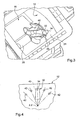
- FIG. 3 shows how the elastic tongue 30 bears against the contact zone 31 of the wall 12 of the housing 10. It can also be seen in this figure that the arm 32 is connected to two elements 40 forming a counter-support which are also connected to the shutter shaft. This results in a reinforcement of the arm 32 and, consequently, of the elastic tongue 30.
- the wall 12 is internally provided with several recesses or notches 42 located equidistant from the axis of rotation XX and in defined angular positions. These recesses 42 form notches intended to receive the curved end 34 of the elastic tongue 30 in a multiplicity of angular positions. selected.
- the elastic tongue ensures not only compensation of the play of the flap, but also a function of indexing the positions of the flap.
- Figure 5 The embodiment of Figure 5 is similar to that of Figure 1 and the common elements are designated by the same reference numerals.
- the elastic tongue 30 has here an end 44, not curved as in the previous embodiment, but extending in the extension of the arm 32.
- the elastic tongue 30 is arranged to bear against a contact zone 46 of the first wall 12, which is formed by the internal face of a cylindrical rib 48 projecting from the wall 12 and extending towards the inside of the housing.
- the cylindrical rib 48 is made in one piece with the wall 12, for example by molding a plastic material, and it is centered on the axis XX. It can constitute a complete circle or an arc of a circle.
- the resilient tongue 30 exerts a bearing force F2 in a radial direction YY, perpendicular to the axis XX, and in the downward direction in FIG. 5.
- This produces a reaction force which tends to bias the body 18 of the flap in a direction D2 opposite the force F2.
- the body 18 of the flap is thus biased in a radial direction, thus eliminating any radial clearance between the body of the flap and the housing.
- the contact zone 46 (internal face of the rib 48 of FIG. 5) is internally provided with several recesses or notches 50 located equidistant from the axis of rotation XX and in defined angular positions. These recesses 50 form notches intended to receive the end 44 of the resilient tongue 30 in a multiplicity of selected angular positions.
- the elastic tongue not only provides compensation for the clearance of component, but also an indexing function for the shutter positions.
- the flap can be equipped with several tabs cooperating with respective contact areas to compensate for different types of games.
- the invention is particularly applicable to heating-ventilation devices and / or air conditioning of the passenger compartment of motor vehicles.
Landscapes
- Physics & Mathematics (AREA)
- Thermal Sciences (AREA)
- Engineering & Computer Science (AREA)
- Mechanical Engineering (AREA)
- Air-Conditioning For Vehicles (AREA)
- Air-Flow Control Members (AREA)
- Lift Valve (AREA)
- Catching Or Destruction (AREA)
- Cooling Or The Like Of Electrical Apparatus (AREA)
Claims (11)
- Heizungs- und/oder Belüftungseinrichtung, vor allem für Kraftfahrzeuge, bestehend aus einer Luftregelungsklappe (16), welche in einem Gehäuse (10) gelagert ist, wobei die Klappe ein mit der Drehwelle (20) formschlüssig verbundenes Hauptstück (18) aufweist, und das Gehäuse (10) eine erste Wand (12) und eine zweite entgegengesetzte Wand (14) aufweist, zwischen denen sich das Hauptstück (18) der Klappe erstreckt, wobei die Klappe (16) mit mindestens einer elastischen Zunge (30) versehen ist, welche so angeordnet ist, dass sie gegen mindestens einen Kontaktbereich (31, 46) der ersten Wand (12) aufliegt und das Hauptstück (18) der Klappe in einer der von der elastischen Zunge auf den Kontaktbereich ausgeübten Kraft (F1, F2) entgegengesetzten Richtung (D1, D2) beansprucht, dadurch gekennzeichnet, dass die Wände (12, 14) von der Welle (20) der Klappe durchdrungen sind, wobei der Kontaktbereich (31, 46) der ersten Wand (12) Indexierungsmittel (42, 50) umfasst; welche geeignet sind, mit der elastischen Zunge (30) zusammenzuwirken, um die Klappe (16) in festgelegten winkeligen Stellungen zu halten.
- Einrichtung nach Anspruch 1, dadurch gekennzeichnet, dass die elastische Zunge (30) derart angeordnet ist, dass sie gegen den Kontaktbereich (31) der ersten Wand (12) aufliegen kann und das Hauptstück (18) der Klappe in einer axialen Richtung (XX) gegen die zweite Wand (14) beansprucht.
- Einrichtung nach Anspruch 1, dadurch gekennzeichnet, dass die elastische Zunge (30) derart angeordnet ist, dass sie gegen den Kontaktbereich (46) der ersten Wand (12) aufliegen kann und das Hauptstück (18) der Klappe in einer radialen Richtung (YY) beansprucht.
- Einrichtung nach einem der Ansprüche 1 bis 3, dadurch gekennzeichnet, dass die elastische Zunge (30) einen sich zu der Welle (20) radial erstreckenden Arm (32) aufweist.
- Einrichtung nach Anspruch 4, dadurch gekennzeichnet, dass der Arm (32) der elastischen Zunge (30) mit einem gebogenen Ende (34) versehen ist.
- Einrichtung nach einem der Ansprüche 1 bis 5, dadurch gekennzeichnet, dass der Arm (32) mit einer an der Verbindungsstelle zwischen dem Hauptstück (18) und der Welle (20) der Klappe gebildeten Nabe (24) formschlüssig verbunden ist.
- Einrichtung nach einem der Ansprüche 1 bis 6, dadurch gekennzeichnet, dass die elastische Zunge (30) mit der Klappe (16) aus einem einzigen Stück durch Formen eines Kunststoffes gebildet ist.
- Einrichtung g nach einem der Ansprüche 1 bis 6, dadurch gekennzeichnet, dass die elastische Zunge mindestens teilweise mit der Klappe (16) aus einem einzigen Stück durch Formen eines Kunststoffes gebildet ist.
- Einrichtung nach Anspruch 8, dadurch gekennzeichnet, dass die elastische Zunge (30) aus einem Teil, welcher mit der Klappe aus einem einzigen Teil gebildet ist und einem eingespritzten Teil (38) besteht.
- Einrichtung nach den Ansprüchen 5 bis 9, als Kombinationen verstanden, dadurch gekennzeichnet, dass der eingespritzte Teil (38) das gebogene Ende (34) der Zunge umfasst.
- Einrichtung nach einem der Ansprüche 1 bis 10, dadurch gekennzeichnet, dass das Hauptstück (18) der Klappe von einer Dichtung (22) umgeben ist, welche die Dichtheit mit der ersten Wand (12) und der zweiten Wand (14) gewährleistet.
Applications Claiming Priority (2)
| Application Number | Priority Date | Filing Date | Title |
|---|---|---|---|
| FR0310140A FR2859135B1 (fr) | 2003-08-25 | 2003-08-25 | Dispositif de chauffage -ventilation et/ou climatisation comprenant un volet de reglage d'air loge dans un boitier |
| FR0310140 | 2003-08-25 |
Publications (2)
| Publication Number | Publication Date |
|---|---|
| EP1510377A1 EP1510377A1 (de) | 2005-03-02 |
| EP1510377B1 true EP1510377B1 (de) | 2007-12-12 |
Family
ID=34089853
Family Applications (1)
| Application Number | Title | Priority Date | Filing Date |
|---|---|---|---|
| EP04013749A Expired - Lifetime EP1510377B1 (de) | 2003-08-25 | 2004-06-11 | Heizungs-Lüftungs- und/oder Klimaanlage mit einer in einem Gehäuse angeordneten Luftregelklappe |
Country Status (7)
| Country | Link |
|---|---|
| EP (1) | EP1510377B1 (de) |
| CN (1) | CN100431862C (de) |
| AT (1) | ATE380693T1 (de) |
| BR (1) | BRPI0402575A (de) |
| DE (1) | DE602004010582T2 (de) |
| ES (1) | ES2297301T3 (de) |
| FR (1) | FR2859135B1 (de) |
Families Citing this family (2)
| Publication number | Priority date | Publication date | Assignee | Title |
|---|---|---|---|---|
| DE102013211833A1 (de) * | 2013-06-21 | 2014-12-24 | Behr Gmbh & Co. Kg | Luftverteilungseinrichtung für eine Heiz- oder Klimaanlage, insbesondere für ein Kraftfahrzeug |
| DE102014226952A1 (de) * | 2014-12-23 | 2016-06-23 | Mahle International Gmbh | Lüftungs-/Klimatisierungssystem eines Kraftfahrzeugs |
Family Cites Families (3)
| Publication number | Priority date | Publication date | Assignee | Title |
|---|---|---|---|---|
| DE3818565A1 (de) * | 1988-06-01 | 1989-12-07 | Bosch Gmbh Robert | Schwenkbares leitelement, insbesondere fuer eine zu einem kraftfahrzeug gehoerende anlage zur klimatisierung dessen fahrgastraumes |
| DE19530003C2 (de) * | 1995-08-16 | 1998-06-04 | Behr Gmbh & Co | Drehbewegliche Strömungssteuerklappe |
| DE10053850A1 (de) * | 2000-10-30 | 2002-05-08 | Bosch Gmbh Robert | Exzenterventil |
-
2003
- 2003-08-25 FR FR0310140A patent/FR2859135B1/fr not_active Expired - Fee Related
-
2004
- 2004-06-11 DE DE602004010582T patent/DE602004010582T2/de not_active Expired - Fee Related
- 2004-06-11 EP EP04013749A patent/EP1510377B1/de not_active Expired - Lifetime
- 2004-06-11 AT AT04013749T patent/ATE380693T1/de not_active IP Right Cessation
- 2004-06-11 ES ES04013749T patent/ES2297301T3/es not_active Expired - Lifetime
- 2004-06-30 BR BR0402575-0A patent/BRPI0402575A/pt not_active IP Right Cessation
- 2004-08-04 CN CNB2004100558334A patent/CN100431862C/zh not_active Expired - Fee Related
Also Published As
| Publication number | Publication date |
|---|---|
| ATE380693T1 (de) | 2007-12-15 |
| EP1510377A1 (de) | 2005-03-02 |
| BRPI0402575A (pt) | 2005-05-17 |
| DE602004010582T2 (de) | 2008-12-04 |
| DE602004010582D1 (de) | 2008-01-24 |
| FR2859135B1 (fr) | 2006-02-24 |
| FR2859135A1 (fr) | 2005-03-04 |
| ES2297301T3 (es) | 2008-05-01 |
| CN100431862C (zh) | 2008-11-12 |
| CN1590143A (zh) | 2005-03-09 |
Similar Documents
| Publication | Publication Date | Title |
|---|---|---|
| EP0635651B1 (de) | Lageranordnung für eine rotierende Welle einer Scheibenwischeranlage | |
| EP2456053B1 (de) | Motorbefestigungsvorrichtung, insbesondere für eine kühlerventilatorgruppe | |
| FR2629159A1 (fr) | Dispositif de debrayage pour un embrayage de vehicule automobile | |
| EP1510377B1 (de) | Heizungs-Lüftungs- und/oder Klimaanlage mit einer in einem Gehäuse angeordneten Luftregelklappe | |
| EP1136342B1 (de) | Druckstückelementenanordnung für eine Kraftfahrzeug- Zahnstangenlenkung | |
| FR2797013A1 (fr) | Appareil d'accouplement hydrocinetique, notamment pour vehicule automobile | |
| EP1919724B1 (de) | Lufttechnisches querglied für ein kraftfahrzeug | |
| FR2892993A1 (fr) | Dispositif aerodynamique pour un vehicule automobile et vehicule automobile comportant au moins un tel dispositif aerodynamique. | |
| FR2571458A1 (fr) | Butee d'embrayage | |
| EP3599404A1 (de) | Regulierbare befestigungshalterung für die montage eines rohrförmigen artikels auf einem externen organ | |
| EP2780198B1 (de) | Verkleidungsteil für kraftfahrzeuglenksäule | |
| EP0704356A1 (de) | Trägerstruktur einer Scheibenwischeranlage | |
| EP1707843B1 (de) | Zweimassenschwungrad für ein Kraftfahrzeug | |
| WO2020016356A1 (fr) | Coupelle de butée de suspension à insert métallique et butée de suspension associée | |
| EP1679447B1 (de) | Wälzlagereinheit | |
| EP2148804B1 (de) | Einheit bestehend aus einem Kraftfahrzeug-Karosserieelement, in welchem wenigstens ein Loch gebildet ist, und einer Vorrichtung zum Verschliessen des wenigstens einen Lochs | |
| FR2511738A1 (fr) | Verin a depression | |
| EP1749682A1 (de) | Luftdüse, insbesondere für ein Kraftfahrzeug, mit schwenkbaren Luftleitlamellen, die auf einem drehbaren Gehäuse montiert sind | |
| EP1127773B1 (de) | Zahnstangenführung für eine Kraftfahrzeuglenkung | |
| WO2024165800A1 (fr) | Montage de bavettes de roue sur un élément de carrosserie | |
| FR2894677A1 (fr) | Dispositif pour la mesure de mouvements de rotation d'un roulement de moyeu | |
| FR2810949A1 (fr) | Ensemble de buse de degivrage et equipement correspondant | |
| FR3089271A1 (fr) | Soufflet de protection et joint de transmission équipé d'un tel soufflet | |
| FR2850719A1 (fr) | Agrafe de fixation d'un element de carrosserie sur une structure d'un vehicule automobile | |
| FR2764950A1 (fr) | Dispositif anti-boitement et anti-extraction d'un ensemble coulissant |
Legal Events
| Date | Code | Title | Description |
|---|---|---|---|
| PUAI | Public reference made under article 153(3) epc to a published international application that has entered the european phase |
Free format text: ORIGINAL CODE: 0009012 |
|
| AK | Designated contracting states |
Kind code of ref document: A1 Designated state(s): AT BE BG CH CY CZ DE DK EE ES FI FR GB GR HU IE IT LI LU MC NL PL PT RO SE SI SK TR |
|
| AX | Request for extension of the european patent |
Extension state: AL HR LT LV MK |
|
| 17P | Request for examination filed |
Effective date: 20050805 |
|
| RAP1 | Party data changed (applicant data changed or rights of an application transferred) |
Owner name: VALEO SYSTEMES THERMIQUES |
|
| AKX | Designation fees paid |
Designated state(s): AT BE BG CH CY CZ DE DK EE ES FI FR GB GR HU IE IT LI LU MC NL PL PT RO SE SI SK TR |
|
| GRAP | Despatch of communication of intention to grant a patent |
Free format text: ORIGINAL CODE: EPIDOSNIGR1 |
|
| GRAS | Grant fee paid |
Free format text: ORIGINAL CODE: EPIDOSNIGR3 |
|
| GRAA | (expected) grant |
Free format text: ORIGINAL CODE: 0009210 |
|
| RIN1 | Information on inventor provided before grant (corrected) |
Inventor name: BECK, PATRICK |
|
| AK | Designated contracting states |
Kind code of ref document: B1 Designated state(s): AT BE BG CH CY CZ DE DK EE ES FI FR GB GR HU IE IT LI LU MC NL PL PT RO SE SI SK TR |
|
| REG | Reference to a national code |
Ref country code: GB Ref legal event code: FG4D Free format text: NOT ENGLISH |
|
| REG | Reference to a national code |
Ref country code: CH Ref legal event code: EP |
|
| REG | Reference to a national code |
Ref country code: IE Ref legal event code: FG4D Free format text: LANGUAGE OF EP DOCUMENT: FRENCH |
|
| REF | Corresponds to: |
Ref document number: 602004010582 Country of ref document: DE Date of ref document: 20080124 Kind code of ref document: P |
|
| PG25 | Lapsed in a contracting state [announced via postgrant information from national office to epo] |
Ref country code: SE Free format text: LAPSE BECAUSE OF FAILURE TO SUBMIT A TRANSLATION OF THE DESCRIPTION OR TO PAY THE FEE WITHIN THE PRESCRIBED TIME-LIMIT Effective date: 20080312 |
|
| REG | Reference to a national code |
Ref country code: ES Ref legal event code: FG2A Ref document number: 2297301 Country of ref document: ES Kind code of ref document: T3 |
|
| PG25 | Lapsed in a contracting state [announced via postgrant information from national office to epo] |
Ref country code: PL Free format text: LAPSE BECAUSE OF FAILURE TO SUBMIT A TRANSLATION OF THE DESCRIPTION OR TO PAY THE FEE WITHIN THE PRESCRIBED TIME-LIMIT Effective date: 20071212 Ref country code: SI Free format text: LAPSE BECAUSE OF FAILURE TO SUBMIT A TRANSLATION OF THE DESCRIPTION OR TO PAY THE FEE WITHIN THE PRESCRIBED TIME-LIMIT Effective date: 20071212 Ref country code: FI Free format text: LAPSE BECAUSE OF FAILURE TO SUBMIT A TRANSLATION OF THE DESCRIPTION OR TO PAY THE FEE WITHIN THE PRESCRIBED TIME-LIMIT Effective date: 20071212 Ref country code: NL Free format text: LAPSE BECAUSE OF FAILURE TO SUBMIT A TRANSLATION OF THE DESCRIPTION OR TO PAY THE FEE WITHIN THE PRESCRIBED TIME-LIMIT Effective date: 20071212 |
|
| NLV1 | Nl: lapsed or annulled due to failure to fulfill the requirements of art. 29p and 29m of the patents act | ||
| PG25 | Lapsed in a contracting state [announced via postgrant information from national office to epo] |
Ref country code: AT Free format text: LAPSE BECAUSE OF FAILURE TO SUBMIT A TRANSLATION OF THE DESCRIPTION OR TO PAY THE FEE WITHIN THE PRESCRIBED TIME-LIMIT Effective date: 20071212 |
|
| GBV | Gb: ep patent (uk) treated as always having been void in accordance with gb section 77(7)/1977 [no translation filed] | ||
| PGFP | Annual fee paid to national office [announced via postgrant information from national office to epo] |
Ref country code: CZ Payment date: 20080602 Year of fee payment: 5 Ref country code: ES Payment date: 20080620 Year of fee payment: 5 |
|
| PG25 | Lapsed in a contracting state [announced via postgrant information from national office to epo] |
Ref country code: RO Free format text: LAPSE BECAUSE OF FAILURE TO SUBMIT A TRANSLATION OF THE DESCRIPTION OR TO PAY THE FEE WITHIN THE PRESCRIBED TIME-LIMIT Effective date: 20071212 Ref country code: SK Free format text: LAPSE BECAUSE OF FAILURE TO SUBMIT A TRANSLATION OF THE DESCRIPTION OR TO PAY THE FEE WITHIN THE PRESCRIBED TIME-LIMIT Effective date: 20071212 |
|
| PG25 | Lapsed in a contracting state [announced via postgrant information from national office to epo] |
Ref country code: PT Free format text: LAPSE BECAUSE OF FAILURE TO SUBMIT A TRANSLATION OF THE DESCRIPTION OR TO PAY THE FEE WITHIN THE PRESCRIBED TIME-LIMIT Effective date: 20080512 |
|
| PGFP | Annual fee paid to national office [announced via postgrant information from national office to epo] |
Ref country code: IT Payment date: 20080621 Year of fee payment: 5 |
|
| REG | Reference to a national code |
Ref country code: IE Ref legal event code: FD4D |
|
| PLBE | No opposition filed within time limit |
Free format text: ORIGINAL CODE: 0009261 |
|
| STAA | Information on the status of an ep patent application or granted ep patent |
Free format text: STATUS: NO OPPOSITION FILED WITHIN TIME LIMIT |
|
| PG25 | Lapsed in a contracting state [announced via postgrant information from national office to epo] |
Ref country code: IE Free format text: LAPSE BECAUSE OF FAILURE TO SUBMIT A TRANSLATION OF THE DESCRIPTION OR TO PAY THE FEE WITHIN THE PRESCRIBED TIME-LIMIT Effective date: 20071212 Ref country code: DK Free format text: LAPSE BECAUSE OF FAILURE TO SUBMIT A TRANSLATION OF THE DESCRIPTION OR TO PAY THE FEE WITHIN THE PRESCRIBED TIME-LIMIT Effective date: 20071212 |
|
| PGFP | Annual fee paid to national office [announced via postgrant information from national office to epo] |
Ref country code: DE Payment date: 20080613 Year of fee payment: 5 |
|
| 26N | No opposition filed |
Effective date: 20080915 |
|
| PG25 | Lapsed in a contracting state [announced via postgrant information from national office to epo] |
Ref country code: GB Free format text: LAPSE BECAUSE OF FAILURE TO SUBMIT A TRANSLATION OF THE DESCRIPTION OR TO PAY THE FEE WITHIN THE PRESCRIBED TIME-LIMIT Effective date: 20071212 |
|
| BERE | Be: lapsed |
Owner name: VALEO SYSTEMES THERMIQUES Effective date: 20080630 |
|
| PG25 | Lapsed in a contracting state [announced via postgrant information from national office to epo] |
Ref country code: GR Free format text: LAPSE BECAUSE OF FAILURE TO SUBMIT A TRANSLATION OF THE DESCRIPTION OR TO PAY THE FEE WITHIN THE PRESCRIBED TIME-LIMIT Effective date: 20080313 Ref country code: MC Free format text: LAPSE BECAUSE OF NON-PAYMENT OF DUE FEES Effective date: 20080630 |
|
| REG | Reference to a national code |
Ref country code: CH Ref legal event code: PL |
|
| PG25 | Lapsed in a contracting state [announced via postgrant information from national office to epo] |
Ref country code: BE Free format text: LAPSE BECAUSE OF NON-PAYMENT OF DUE FEES Effective date: 20080630 |
|
| REG | Reference to a national code |
Ref country code: FR Ref legal event code: ST Effective date: 20090228 |
|
| PG25 | Lapsed in a contracting state [announced via postgrant information from national office to epo] |
Ref country code: BG Free format text: LAPSE BECAUSE OF FAILURE TO SUBMIT A TRANSLATION OF THE DESCRIPTION OR TO PAY THE FEE WITHIN THE PRESCRIBED TIME-LIMIT Effective date: 20080312 Ref country code: EE Free format text: LAPSE BECAUSE OF FAILURE TO SUBMIT A TRANSLATION OF THE DESCRIPTION OR TO PAY THE FEE WITHIN THE PRESCRIBED TIME-LIMIT Effective date: 20071212 |
|
| PG25 | Lapsed in a contracting state [announced via postgrant information from national office to epo] |
Ref country code: CH Free format text: LAPSE BECAUSE OF NON-PAYMENT OF DUE FEES Effective date: 20080630 Ref country code: LI Free format text: LAPSE BECAUSE OF NON-PAYMENT OF DUE FEES Effective date: 20080630 |
|
| PG25 | Lapsed in a contracting state [announced via postgrant information from national office to epo] |
Ref country code: CY Free format text: LAPSE BECAUSE OF FAILURE TO SUBMIT A TRANSLATION OF THE DESCRIPTION OR TO PAY THE FEE WITHIN THE PRESCRIBED TIME-LIMIT Effective date: 20071212 |
|
| PG25 | Lapsed in a contracting state [announced via postgrant information from national office to epo] |
Ref country code: FR Free format text: LAPSE BECAUSE OF NON-PAYMENT OF DUE FEES Effective date: 20080630 |
|
| PG25 | Lapsed in a contracting state [announced via postgrant information from national office to epo] |
Ref country code: CZ Free format text: LAPSE BECAUSE OF NON-PAYMENT OF DUE FEES Effective date: 20090611 |
|
| PG25 | Lapsed in a contracting state [announced via postgrant information from national office to epo] |
Ref country code: DE Free format text: LAPSE BECAUSE OF NON-PAYMENT OF DUE FEES Effective date: 20100101 |
|
| PG25 | Lapsed in a contracting state [announced via postgrant information from national office to epo] |
Ref country code: HU Free format text: LAPSE BECAUSE OF FAILURE TO SUBMIT A TRANSLATION OF THE DESCRIPTION OR TO PAY THE FEE WITHIN THE PRESCRIBED TIME-LIMIT Effective date: 20080613 Ref country code: LU Free format text: LAPSE BECAUSE OF NON-PAYMENT OF DUE FEES Effective date: 20080611 |
|
| REG | Reference to a national code |
Ref country code: ES Ref legal event code: FD2A Effective date: 20090612 |
|
| PG25 | Lapsed in a contracting state [announced via postgrant information from national office to epo] |
Ref country code: TR Free format text: LAPSE BECAUSE OF FAILURE TO SUBMIT A TRANSLATION OF THE DESCRIPTION OR TO PAY THE FEE WITHIN THE PRESCRIBED TIME-LIMIT Effective date: 20071212 |
|
| PG25 | Lapsed in a contracting state [announced via postgrant information from national office to epo] |
Ref country code: ES Free format text: LAPSE BECAUSE OF NON-PAYMENT OF DUE FEES Effective date: 20090612 |
|
| PG25 | Lapsed in a contracting state [announced via postgrant information from national office to epo] |
Ref country code: IT Free format text: LAPSE BECAUSE OF NON-PAYMENT OF DUE FEES Effective date: 20090611 |