EP1510338A1 - Reinigungsvorrichtung für eine Beschichtungseinheit in einer Verarbeitungsmaschine - Google Patents
Reinigungsvorrichtung für eine Beschichtungseinheit in einer Verarbeitungsmaschine Download PDFInfo
- Publication number
- EP1510338A1 EP1510338A1 EP04018909A EP04018909A EP1510338A1 EP 1510338 A1 EP1510338 A1 EP 1510338A1 EP 04018909 A EP04018909 A EP 04018909A EP 04018909 A EP04018909 A EP 04018909A EP 1510338 A1 EP1510338 A1 EP 1510338A1
- Authority
- EP
- European Patent Office
- Prior art keywords
- cleaning
- cleaning device
- coupled
- spray
- doctor blade
- Prior art date
- Legal status (The legal status is an assumption and is not a legal conclusion. Google has not performed a legal analysis and makes no representation as to the accuracy of the status listed.)
- Withdrawn
Links
Images

Classifications
-
- B—PERFORMING OPERATIONS; TRANSPORTING
- B41—PRINTING; LINING MACHINES; TYPEWRITERS; STAMPS
- B41F—PRINTING MACHINES OR PRESSES
- B41F23/00—Devices for treating the surfaces of sheets, webs, or other articles in connection with printing
- B41F23/08—Print finishing devices, e.g. for glossing prints
-
- B—PERFORMING OPERATIONS; TRANSPORTING
- B41—PRINTING; LINING MACHINES; TYPEWRITERS; STAMPS
- B41F—PRINTING MACHINES OR PRESSES
- B41F35/00—Cleaning arrangements or devices
- B41F35/04—Cleaning arrangements or devices for inking rollers
Definitions
- the invention relates to a cleaning device for a coating unit in a processing machine according to the preamble of claim 1.
- a cleaning device can be used in coating units, in particular of printing or coating machines, including painting machines, or in processing machines combined in printing and coating units.
- a cleaning device of this type is known from EP 1 097 813 B1 known.
- Each coating unit has a substrate leading cylinder, a form cylinder and a dosing system with an applicator roll on.
- the applicator roll is the with a feed and a return system for a circulating Cleaning fluid coupled cleaning device on and allocated assignable.
- the cleaning device as a to applicator roller over the roll width extending Cleaning doctor blade system is formed and is in the direction of rotation the applicator roller upstream of the metering system.
- the Cleaning doctor blade system is a chamber doctor blade with two squeegee blades and lateral seals which seal the doctoring chamber, educated. Supply and return system for the Cleaning fluid open into the interior of the doctor blade chamber.
- the invention is based on the object, a cleaning device to create the type described above, the one improved cleaning of a neighboring assigned applicator roll allowed and the cleaning time further shortened.
- a first advantage is due to the fact that the cleaning device to improve the coating quality in contributes a coating unit.
- the application roller remains always in a process-stable state by these continuously or discontinuously from contamination is cleaned within the coating unit. Likewise is If necessary, the application roller by means of the cleaning device cleanable after each change of order. It is also advantageous that when cleaning the applicator roll as needed at the same time the respective dosing system cleaned or replaced can be.
- a second advantage is that at least one cleaning fluid be fed by pressure to the applicator roll and on the lateral surface is sprayable and improved Cleaning result, the cleaning time is shortened.
- the cleaning device is preferred as extending across the width of the applicator roll Cleaning doctor blade system with roller surface paraxial doctor blades and side seals formed is, so that the blade chamber sufficiently sealed off is.
- Inside the squeegee chamber is for the supplied under pressure Cleaning fluid arranged a spray.
- the Spraying here leads at least one cleaning fluid each of the doctor chamber associated portion of the applicator roll to.
- any supplied cleaning fluid is heated.
- the application roller is depending on the training with a relative smooth as well as a gridded, with wells and bars provided lateral surface cleanable.
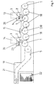
- a processing machine for example a sheet material processing printing machine, has in the conveying direction 5 of Substrate a first and a second coating unit 13, 14 on. Between the coating units 13, 14 a dryer unit 15 is preferably arranged.
- the second Coating unit 14 is a boom 19 downstream, the et al is formed by circulating conveyor systems 21, which the sheet-shaped substrates on a delivery stack 22nd interpret. For the transport of sheet-shaped substrates are within the processing machine more pressure cylinder 1 and transfer cylinder 18 in a conventional manner intended.
- the first coating unit 13 is for example as Lackwerk or flexographic printing formed and consists of a leading the substrate, here sheet-guiding, pressure cylinder 1, one can be brought into contact with the printing cylinder 1 in contact Form cylinder 2 and a metering system 20 for the coating medium.
- the forme cylinder bears 2 is a flexible high pressure plate, alternatively, for example a blanket can be arranged.
- the dosing system 20 has in this training a to the form cylinder 2 on and Ab ause applicator roll 3, which with a chambered doctor blade 4 is coupled.
- the application roller 3 is preferably a through Cups and webs formed anilox roller.
- the second coating unit 14 is also as a coating unit or flexographic printing formed and in turn consists of the Printing material leading impression cylinder 1, forme cylinder 2 and Dosing system 20.
- the dosing system 20 for the coating medium by a to the forme cylinder 2 adjustable / off applicator roller 3 and a metering roller 23 formed.
- the form cylinder 2 to the impression cylinder 1 in a gap 6 on or off.
- the coating unit 13 and / or 14 has a cleaning device arranged separately from the dosing system 20 on the applicator roll 3 on / off and this is cleans.
- the cleaning device consists of one of rasterized application roller 3 on / ab suit assigned, about the roll width extending cleaning blade system 8, which with a feed system 9 and a return system 10 is coupled for at least one cleaning fluid.
- the Cleaning doctor blade 8 is in the direction of rotation 7 of the applicator roll 3 before the on / off dosing system 20 arranged.
- the Cleaning device is preferably with the machine control connected by circuitry and is by means of predetermined Washing programs automatically activated, including on the application roller 3 on / off
- the cleaning doctor blade system 8 has a first doctor blade 11 and a second doctor blade 12 and side seals, so that in conjunction with the lateral surface of the applicator roll 3 forms a doctor chamber 16.
- In the doctoring chamber 16 is a directed to the applicator roller 3 spray 17th arranged.
- the spray device 17 is preferably by means of a detachable Coupling 24 coupled to the feed system 9.
- About the feeding system 9 is at least one cleaning fluid under pressure be fed to the spray 17 (and by means of the spray 17 on the respective section of the applicator roll 3 applicable).
- the delivery system 9 is provided with at least one Reservoir coupled for at least one cleaning fluid.
- the doctor chamber 16 is preferably by means of a detachable Coupling 25 with the return system 10 for contaminated Cleaning fluid or paint / ink residues etc. coupled, which is coupled with at least one reservoir.
- At the bottom Area of the doctor chamber 16 is preferably one with the Return system 10 coupled drain arranged.
- the feeding system 9 and the return system 10 and, if necessary, the spray device 17 are with multiple circuits for separate funded cleaning fluids executable. For example a cycle for dispersion varnish or another cycle for UV varnish and possibly an additional water circuit designed.
- the circuits are correspondingly separate containers assigned. In the respective cycle is at least a separate row of nozzles of the spray 17 included.
- the individual circuits are preferably from the control station off automatically preselected.
- the cleaning doctor system 8 is fast by the couplings 24,25 from the supply or Return system 9,10 separable and thus is the cleaning blade system 8 easily from the respective coating unit 13th or 14 removable or exchangeable for a second.
- the spraying device 17 can be executed in various configurations.
- the spraying device 17 is equipped with a plurality of nozzles directed onto the applicator roller 3 and extends substantially over the roller width of the applicator roller 3.
- the spray device 17 is formed from at least one spray tube extending substantially over the roll width of the application roller 3.
- Each spray tube has a plurality of nozzles distributed over the length distributed at intervals, directed onto the application roller 3 and each spray tube is coupled within the delivery system 9 with its own supply line.
- the spraying device 17 has a spraying head (with nozzles) directed axially parallel to the applicator roller 3 within the doctoring chamber 16 and directed onto the applicator roller 3.
- all nozzles are low-pressure nozzles with a formed relatively high volume flow of cleaning fluid. It was found that a volume throughput of about 0.75 to 3.5 liters / minute is favorable.
- sprayers 17 are for example with a first cleaning fluid, For example, detergent for dispersion varnish, as well as with a second cleaning fluid, for example water, operated.
- a second cleaning fluid for example water
- the sprayers 17 are additional with another cleaning fluid, for example Detergent for UV coatings (UV inks) operable.
- Feeding system 9 and return system 10 are coupled to at least one pumping device.
- the feed system 9 is coupled with at least one feed pump and the return system 10 with a suction pump.
- the feed system 9 is coupled to at least one feed pump and the return system 10 is operated by gravity.
- the cleaning doctor blade system 8 of the application roller 3 is preferred arranged opposite to the dosing system 20.
- a Processing machine for sheet-shaped substrates is preferably the dosing system 20, for example the Chamber doctor blade 4, on the boom side and the cleaning doctor blade system 8 assigned on the investor side of the applicator roll 3 ( Figure 2).
- a heat source in particular a heater, associated with heating the cleaning fluid.
- the heating takes place in the feed system 9.
- a further improvement of the cleaning effect on the Application roller 3 is at cleaning cleaning doctor 8 (and activated spray device 17) thereby achievable, by the applicator roller 3 periodically with changing direction of rotation 7, 7 'is drivable.
- the spray device 17 itself as a blowing device usable by the feeding of cleaning fluid of the spray 17th Blowing air is supplied.
- the blast air line is separate or integrated into the feed system 9 and is preferably by means of a coupling with the cleaning blade system 8 releasably coupled, so that analogously to the feed / return system 9,10 a fast separation is feasible.
- the blowing direction of Blower is not limited to the applicator roll 3. Rather, by means of a suitable Blasdüsenan note - after Emptying the doctor chamber 16 of cleaning fluid - also the Drying inside this doctoring chamber 16 are supported.
- the operation of the cleaning device is as follows: If, for example, on the applicator roll 3 soiling or an order change is provided, the cleaning doctor blade system 8 is set to the applicator roller 3 and at least one cleaning fluid to the sprayer manually or via a stored in a machine control washing program Supplied 17 and applied to the rotatable (rotational direction 7, 7 ') driven applicator roll 3.
- the dosing system 20 is inactive in this case, for example, the chambered doctor blade 4 is turned off by the applicator roller 3.
- the respective cleaning fluid dissolves the paint, the paint or other impurities on the applicator roll 3 and supplies them via the return system 10 to a container. Depending on the degree of soiling or the surface of the applicator roll 3, the process is repeated several times.
- cleaning fluids can be fed successively to the application roller. If necessary, the surface of the application roller 3 by means of blowing air dried. Thereafter, the cleaning doctor blade system 8 is stopped by the application roller 3 and the dosing system 20 can be reactivated.
Landscapes
- Engineering & Computer Science (AREA)
- Mechanical Engineering (AREA)
- Inking, Control Or Cleaning Of Printing Machines (AREA)
- Coating Apparatus (AREA)
- Cleaning By Liquid Or Steam (AREA)
Abstract
Description
Eine derartige Reinigungsvorrichtung ist in Beschichtungseinheiten insbesondere von Druck- bzw. Beschichtungsmaschinen, einschließlich Lackiermaschinen, bzw. in aus Druck- und Lackiereinheiten kombinierten Verarbeitungsmaschinen einsetzbar.
- Fig. 1
- eine Verarbeitungsmaschine mit zwei Beschichtungseinheiten,
- Fig. 2
- eine Beschichtungseinheit mit einem Reinigungsrakelsystem.
In einer ersten Ausbildung ist die Sprüheinrichtung 17 mit mehreren, auf die Auftragwalze 3 gerichteten Düsen bestückt und erstreckt sich im Wesentlichen über die Walzenbreite der Auftragwalze 3.
In zweiter Ausbildung ist die Sprüheinrichtung 17 aus wenigstens einem sich im Wesentlichen über die Walzenbreite der Auftragwalze 3 erstreckenden Sprührohr gebildet. Jedes Sprührohr weist mehrere über die Länge in Abständen verteilt angeordnete, auf die Auftragwalze 3 gerichtete Düsen auf und jedes Sprührohr ist innerhalb des Zuführsystems 9 mit einer eigenen Zuführleitung gekoppelt.
In einer weiteren Ausbildung weist die Sprüheinrichtung 17 einen innerhalb der Rakelkammer 16 achsparallel zur Auftragwalze 3 traversierbaren, auf die Auftragwalze 3 gerichteten Sprühkopf (mit Düsen) auf.
In einer Weiterbildung ist das Zuführsystem 9 mit wenigstens einer Förderpumpe und das Rücklaufsystem 10 mit einer Saugpumpe gekoppelt.
In einer Weiterbildung ist das Zuführsystem 9 mit wenigstens einer Förderpumpe gekoppelt und das Rücklaufsystem 10 ist mittels Schwerkraft betreibbar.
getrocknet. Danach wird das Reinigungsrakelsystem 8 von der Auftragwalze 3 abgestellt und das Dosiersystem 20 kann wieder aktiviert werden.
- 1 -
- Druckzylinder
- 2 -
- Formzylinder
- 3 -
- Auftragwalze
- 4 -
- Kammerrakel
- 5 -
- Förderrichtung
- 6 -
- Spalt
- 7 -
- Drehrichtung
- 8 -
- Reinigungsrakelsystem
- 9 -
- Zuführsystem
- 10 -
- Rücklaufsystem
- 11 -
- erstes Rakelblatt
- 12 -
- zweites Rakelblatt
- 13 -
- Beschichtungseinheit
- 14 -
- Beschichtungseinheit
- 15 -
- Trocknereinheit
- 16 -
- Rakelkammer
- 17 -
- Sprüheinrichtung
- 18 -
- Transferzylinder
- 19 -
- Ausleger
- 20 -
- Dosiersystem
- 21 -
- Fördersystem
- 22 -
- Auslegerstapel
- 23 -
- Dosierwalze
- 24 -
- Kupplung (Zuführsystem)
- 25 -
- Kupplung (Rücklaufsystem)
Claims (10)
- Reinigungsvorrichtung für eine Beschichtungseinheit in einer Verarbeitungsmaschine, wobei die Beschichtungseinheit einen den Bedruckstoff führenden Zylinder, einen Formzylinder und ein Dosiersystem mit einer Auftragwalze für das Beschichtungsmedium sowie ein der Auftragwalze an-/abstellbar zugeordnetes, über deren Walzenbreite sich erstreckendes Reinigungsrakelsystem mit einem Zuführsystem und einem Rücklaufsystem für Reinigungsfluid aufweist, wobei das Reinigungsrakelsystem in Drehrichtung der Auftragwalze vor dem Dosiersystem angeordnet ist,
dadurch gekennzeichnet, dass in einer Rakelkammer (16) des Reinigungsrakelsystems (8) eine auf die Auftragwalze (3) gerichtete Sprüheinrichtung (17) für Reinigungsfluid angeordnet ist,
dass die Sprüheinrichtung (17) mit dem Zuführsystem (9) gekoppelt und über das Zuführsystem (9) wenigstens ein Reinigungsfluid unter Druck zuführbar ist und dass im unteren Bereich der Rakelkammer (16) ein Ablauf des Rücklaufsystems (10) angeordnet ist. - Reinigungsvorrichtung nach Anspruch 1,
dadurch gekennzeichnet, dass die Sprüheinrichtung (17) mit Düsen bestückt ist und sich im Wesentlichen über die Walzenbreite der Auftragwalze (3) erstreckt. - Reinigungsvorrichtung nach Anspruch 1,
dadurch gekennzeichnet, dass die Sprüheinrichtung (17) aus wenigstens einem sich im Wesentlichen über die Walzenbreite der Auftragwalze (3) erstreckenden Sprührohr gebildet ist,
dass jedes Sprührohr mehrere über die Länge in Abständen verteilt angeordnete Düsen aufweist und jedes Sprührohr mit einer eigenen Zuführleitung innerhalb des Zuführsystems (9) gekoppelt ist. - Reinigungsvorrichtung nach Anspruch 1,
dadurch gekennzeichnet, dass die Sprüheinrichtung (17) einen innerhalb der Rakelkammer (16) achsparallel zur Auftragwalze (3) traversierbaren Sprühkopf aufweist. - Reinigungsvorrichtung nach wenigstens Anspruch 1,
dadurch gekennzeichnet, dass das Zuführsystem (9) und das Rücklaufsystem (10) mit wenigstens einer Pumpeneinrichtung gekoppelt ist. - Reinigungsvorrichtung nach wenigstens Anspruch 1, dadurch gekennzeichnet, dass das Zuführsystem (9) mit wenigstens einer Förderpumpe und das Rücklaufsystem mit einer Saugpumpe gekoppelt ist.
- Reinigungsvorrichtung nach wenigstens Anspruch 1,
dadurch gekennzeichnet, dass das Zuführsystem (9) mit wenigstens einer Förderpumpe gekoppelt ist und das Rücklaufsystem (10) mittels Schwerkraft betreibbar ist. - Reinigungsvorrichtung nach wenigstens Anspruch 1,
dadurch gekennzeichnet, dass das Reinigungsrakelsystem (8) der Auftragwalze (3) gegenüberliegend zum Dosiersystem (20) angeordnet ist. - Reinigungsvorrichtung nach wenigstens Anspruch 1,
dadurch gekennzeichnet, dass dem Zuführsystem (9) und/oder dem Rücklaufsystem (10) eine Wärmequelle zum Erwärmen des Reinigungsfluides zugeordnet ist. - Reinigungsvorrichtung nach wenigstens Anspruch 1,
dadurch gekennzeichnet, dass die Auftragwalze (3) bei angestelltem Reinigungsrakelsystem (8) periodisch mit wechselnder Drehrichtung (7, 7') antreibbar ist.
Applications Claiming Priority (2)
| Application Number | Priority Date | Filing Date | Title |
|---|---|---|---|
| DE20313262U | 2003-08-27 | ||
| DE20313262U DE20313262U1 (de) | 2003-08-27 | 2003-08-27 | Reinigungsvorrichtung für eine Beschichtungseinheit in einer Verarbeitungsmaschine |
Publications (1)
| Publication Number | Publication Date |
|---|---|
| EP1510338A1 true EP1510338A1 (de) | 2005-03-02 |
Family
ID=29432940
Family Applications (1)
| Application Number | Title | Priority Date | Filing Date |
|---|---|---|---|
| EP04018909A Withdrawn EP1510338A1 (de) | 2003-08-27 | 2004-08-10 | Reinigungsvorrichtung für eine Beschichtungseinheit in einer Verarbeitungsmaschine |
Country Status (3)
| Country | Link |
|---|---|
| EP (1) | EP1510338A1 (de) |
| JP (1) | JP2005067202A (de) |
| DE (1) | DE20313262U1 (de) |
Cited By (1)
| Publication number | Priority date | Publication date | Assignee | Title |
|---|---|---|---|---|
| EP2298566A1 (de) * | 2009-09-03 | 2011-03-23 | Fujifilm Corporation | Reinigungsvorrichtung, Flüssigkeitsanwendungsvorrichtung und Bilderzeugungsvorrichtung |
Families Citing this family (6)
| Publication number | Priority date | Publication date | Assignee | Title |
|---|---|---|---|---|
| DE102005008937B4 (de) | 2005-02-26 | 2023-11-09 | manroland sheetfed GmbH | Beschichtungseinheit in einer Druckmaschine |
| JP2006256197A (ja) * | 2005-03-18 | 2006-09-28 | Toppan Printing Co Ltd | 版洗浄装置 |
| DE202011101109U1 (de) * | 2011-05-26 | 2012-08-28 | Weros Technology Gmbh | Farbwerk einer Druckmaschine |
| DE102015005535A1 (de) | 2015-05-03 | 2016-11-03 | Harris & Bruno Europe GmbH | Reinigungsvorrichtung für eine Walze, Druck- oder Beschichtungswerk sowie Verfahren zum Reinigen einer Walze |
| DE102016207398B3 (de) * | 2015-09-09 | 2016-08-18 | Koenig & Bauer Ag | Maschinenanordnung zum sequentiellen Bearbeiten mehrerer bogenförmiger jeweils eine Vorderseite und eine Rückseite aufweisender Substrate |
| FR3068642A1 (fr) | 2017-07-07 | 2019-01-11 | Bobst Lyon | Corps principal de chambre a racles, chambre a racles associee et procedes de fabrication associes. |
Citations (4)
| Publication number | Priority date | Publication date | Assignee | Title |
|---|---|---|---|---|
| US5067193A (en) * | 1990-07-26 | 1991-11-26 | Container Graphics Corporation | Rotary printing plate washing apparatus |
| DE29703074U1 (de) * | 1997-02-21 | 1997-04-30 | Goebel Gmbh Maschf | Einrichtung zum Reinigen |
| EP1155862A2 (de) | 2000-05-19 | 2001-11-21 | Riccardo Fumagalli | Vorrichtung und Verfahren zum Reinigen der Gummituchzylinder von Druckmaschinen |
| US6371024B1 (en) * | 1999-10-20 | 2002-04-16 | Man Roland Druckmaschinen Ag | Sheet-fed printing machine with cleaning system |
-
2003
- 2003-08-27 DE DE20313262U patent/DE20313262U1/de not_active Expired - Lifetime
-
2004
- 2004-08-10 EP EP04018909A patent/EP1510338A1/de not_active Withdrawn
- 2004-08-23 JP JP2004242971A patent/JP2005067202A/ja active Pending
Patent Citations (5)
| Publication number | Priority date | Publication date | Assignee | Title |
|---|---|---|---|---|
| US5067193A (en) * | 1990-07-26 | 1991-11-26 | Container Graphics Corporation | Rotary printing plate washing apparatus |
| DE29703074U1 (de) * | 1997-02-21 | 1997-04-30 | Goebel Gmbh Maschf | Einrichtung zum Reinigen |
| US6371024B1 (en) * | 1999-10-20 | 2002-04-16 | Man Roland Druckmaschinen Ag | Sheet-fed printing machine with cleaning system |
| EP1097813B1 (de) | 1999-10-20 | 2003-07-09 | MAN Roland Druckmaschinen AG | Bogenrotationsdruckmaschine mit Druckeinheiten für den Mehrfarbendruck und wenigstens einer Beschichtungseinheit |
| EP1155862A2 (de) | 2000-05-19 | 2001-11-21 | Riccardo Fumagalli | Vorrichtung und Verfahren zum Reinigen der Gummituchzylinder von Druckmaschinen |
Cited By (1)
| Publication number | Priority date | Publication date | Assignee | Title |
|---|---|---|---|---|
| EP2298566A1 (de) * | 2009-09-03 | 2011-03-23 | Fujifilm Corporation | Reinigungsvorrichtung, Flüssigkeitsanwendungsvorrichtung und Bilderzeugungsvorrichtung |
Also Published As
| Publication number | Publication date |
|---|---|
| JP2005067202A (ja) | 2005-03-17 |
| DE20313262U1 (de) | 2003-11-06 |
Similar Documents
| Publication | Publication Date | Title |
|---|---|---|
| EP1097813B1 (de) | Bogenrotationsdruckmaschine mit Druckeinheiten für den Mehrfarbendruck und wenigstens einer Beschichtungseinheit | |
| EP1968794B1 (de) | Verfahren zum steuern einer verarbeitungsmaschine für bogenmaterial | |
| DE19526574C1 (de) | Verfahren und Vorrichtung zum Waschen eines Formzylinders und einer zugeordneten Auftragwalze in einer Druckmaschine | |
| DE102004055749B4 (de) | Versorgungseinrichtung für eine Reinigungsvorrichtung in einer Verarbeitungsmaschine | |
| DE19729985C2 (de) | Vorrichtung zum Lackieren von Bedruckstoffen in einem Offsetdruckwerk einer Rotationsdruckmaschine | |
| EP1510338A1 (de) | Reinigungsvorrichtung für eine Beschichtungseinheit in einer Verarbeitungsmaschine | |
| DE19829095C2 (de) | Bogenführungseinrichtung in einer Druckmaschine | |
| EP1200261B1 (de) | Beschichtungseinrichtung in einer druckmaschine | |
| EP1441908B1 (de) | Druckmaschinenwalzen-reinigungsverfahren und -vorrichtung | |
| DE19757094A1 (de) | Einrichtung zum Beschichten von Bedruckstoffen in einer Druckmaschine | |
| EP0576907B1 (de) | Einrichtung zum Reinigen eines Walzenspaltes in Rotationsdruckmaschinen | |
| EP2397328A1 (de) | Traversierende Farbkastenreinigung | |
| DE19516456C2 (de) | Vorrichtung zur Reinigung einer Rakelvorrichtung für ein Spülfarbwerk einer Rotationsdruckmaschine | |
| EP0878304B1 (de) | Reinigungsvorrichtung für einen Zylinder oder eine Walze einer Druckmaschine | |
| DE102018104534B3 (de) | Sprührohr und druckmaschinenwalzen-reinigungsvorrichtung mit einem sprührohr | |
| EP1389523B1 (de) | Druck- oder Beschichtungsmachine | |
| EP1502740A2 (de) | Einrichtung zur Farbwerksabsaugung | |
| EP0924074B1 (de) | Einrichtung zum Dosieren einer Beschichtungsflüssigkeit für Bedruckstoffe in einer Druckmaschine | |
| EP0924073B1 (de) | Einrichtung zum Dosieren einer Beschichtungsflüssigkeit für Bedruckstoffe in einer Druckmaschine | |
| DE19729977C2 (de) | Offsetdruckwerk zum Lackieren von Bedruckstoffen in einer Rotationsdruckmaschine | |
| EP1110728A1 (de) | Dosiersystem für Beschichtungsflüssigkeiten in einer Beschichtungseinheit | |
| WO2014154873A2 (de) | Verfahren und vorrichtung zum bedrucken eines substrats | |
| EP0378180B1 (de) | Verfahren und Vorrichtung zum Reinigen von Gummituchzylindern einer Rollenrotationsdruckmaschine | |
| DE102014204007B4 (de) | Farbwerk einer Rotationsdruckmaschine | |
| DE19752492C2 (de) | Bogenführungseinrichtung in einer Druckmaschine |
Legal Events
| Date | Code | Title | Description |
|---|---|---|---|
| PUAI | Public reference made under article 153(3) epc to a published international application that has entered the european phase |
Free format text: ORIGINAL CODE: 0009012 |
|
| 17P | Request for examination filed |
Effective date: 20041123 |
|
| AK | Designated contracting states |
Kind code of ref document: A1 Designated state(s): AT BE BG CH CY CZ DE DK EE ES FI FR GB GR HU IE IT LI LU MC NL PL PT RO SE SI SK TR |
|
| AX | Request for extension of the european patent |
Extension state: AL HR LT LV MK |
|
| AKX | Designation fees paid |
Designated state(s): AT BE BG CH CY CZ DE DK EE ES FI FR GB GR HU IE IT LI LU MC NL PL PT RO SE SI SK TR |
|
| RAP1 | Party data changed (applicant data changed or rights of an application transferred) |
Owner name: MANROLAND AG |
|
| 17Q | First examination report despatched |
Effective date: 20090603 |
|
| GRAP | Despatch of communication of intention to grant a patent |
Free format text: ORIGINAL CODE: EPIDOSNIGR1 |
|
| RTI1 | Title (correction) |
Free format text: COATING UNIT WITH A CLEANING DEVICE IN A PROCESSING MACHINE. |
|
| STAA | Information on the status of an ep patent application or granted ep patent |
Free format text: STATUS: THE APPLICATION HAS BEEN WITHDRAWN |
|
| 18W | Application withdrawn |
Effective date: 20100429 |