EP1510282A1 - Vorrichtung zum Remote-Bearbeiten von Werkstücken mittels eines Laserbearbeitungsstrahls - Google Patents
Vorrichtung zum Remote-Bearbeiten von Werkstücken mittels eines Laserbearbeitungsstrahls Download PDFInfo
- Publication number
- EP1510282A1 EP1510282A1 EP03019721A EP03019721A EP1510282A1 EP 1510282 A1 EP1510282 A1 EP 1510282A1 EP 03019721 A EP03019721 A EP 03019721A EP 03019721 A EP03019721 A EP 03019721A EP 1510282 A1 EP1510282 A1 EP 1510282A1
- Authority
- EP
- European Patent Office
- Prior art keywords
- pointer
- marking
- processing point
- scanner optics
- processing
- Prior art date
- Legal status (The legal status is an assumption and is not a legal conclusion. Google has not performed a legal analysis and makes no representation as to the accuracy of the status listed.)
- Granted
Links
- 238000003754 machining Methods 0.000 title description 15
- 238000011156 evaluation Methods 0.000 claims description 19
- 230000003287 optical effect Effects 0.000 claims description 16
- 238000001514 detection method Methods 0.000 claims description 7
- 239000003550 marker Substances 0.000 abstract 2
- 238000003466 welding Methods 0.000 description 5
- 230000004913 activation Effects 0.000 description 2
- 230000001427 coherent effect Effects 0.000 description 1
- 230000001419 dependent effect Effects 0.000 description 1
- 230000000694 effects Effects 0.000 description 1
- 238000010330 laser marking Methods 0.000 description 1
Images
Classifications
-
- B—PERFORMING OPERATIONS; TRANSPORTING
- B23—MACHINE TOOLS; METAL-WORKING NOT OTHERWISE PROVIDED FOR
- B23K—SOLDERING OR UNSOLDERING; WELDING; CLADDING OR PLATING BY SOLDERING OR WELDING; CUTTING BY APPLYING HEAT LOCALLY, e.g. FLAME CUTTING; WORKING BY LASER BEAM
- B23K26/00—Working by laser beam, e.g. welding, cutting or boring
- B23K26/02—Positioning or observing the workpiece, e.g. with respect to the point of impact; Aligning, aiming or focusing the laser beam
- B23K26/04—Automatically aligning, aiming or focusing the laser beam, e.g. using the back-scattered light
Definitions
- the invention relates to a device for remote processing of workpieces by means of a laser processing beam, with a Scanner optics using a numerically controlled Adjusting device is adjustable, wherein the laser processing beam by means of the set scanner optics on at least one Machining point on the workpiece is directable and where the numerical control of the setting device for the scanner optics is programmable by means of a teaching device.
- Such devices are about laser welding or laser marking used by workpieces.
- the scanner optics known devices includes moving scanner mirrors, the adjustable by means of a CNC-controlled adjusting device are that they the laser processing beam on the respective Direct the machining point to the workpiece.
- the laser processing beam is focused with a large focal length.
- Corresponding far is the scanner optics of the workpiece to be machined spaced.
- Previously known scanner optics is before the actual workpiece machining a guided over the scanner optics concerned Directional laser beam by adjusting the scanner optics by means of Joystick or keyboard moved to the future processing station.
- the set value of the CNC control for the adjusting device the scanner optics, which the target course of the Directional laser beam is assigned in the CNC control deposited.
- the subsequent workpiece machining by means of of the laser processing beam is set to the stored setting value resorted.
- the accordingly provided as a marking device Pointer provides an easy way to quickly, easy to handle and exact definition of the workpiece to be included. To capture is the Pointer mark that defines the machining point defined and their location is accordingly the location of the Machining point reproduces itself. Due to the detection the pointer mark that marks a workstation becomes Setting value for the control of the adjusting device for the Scanner optics defined. This set value is mentioned in the Control deposited. In the subsequent workpiece machining the positioning of the scanner optics takes place with recourse on the stored setting value such that they Laser processing beam on the previously by means of the marking device Marked processing point.
- the Pointer mark continuously and thus also detected when she marks no editing point. Takes the pointer mark a situation in which they are the location of a processing station reproduces on the workpiece, so is the evaluation for defining a setting value for the control of Actuator for scanner optics activated.
- the evaluation device is therefore in constant readiness and it only needs to define a set value a triggering measure. For programming the numeric Control for the adjusting device of the scanner optics results Consequently, a very small amount of time.
- the switching signal can be used to activate the evaluation device by means of a manual switch provided on the pointer to generate.
- the generated switching signal can be different Be nature.
- Conceivable are electrical or acoustic Switching signals as well as optical switching signals at the inventive Device produced according to claim 4 Art.
- optical devices for detecting the a processing point marking pointer mark are more preferred in the case Erfindungsbauart optical devices for detecting the a processing point marking pointer mark, in particular Such optical devices with a camera as a detector intended for the pointer mark. Such devices have proven in practice many times. In conjunction with a optical device for detecting the pointer mark recommends in particular the generation of an optical switching signal to activate the evaluation device.
- the device is preferred according to claim 10. After the pointer marking a machining point with the processing point and the optical axis of Device for detecting the pointer mark between the scanner optics and the workpiece with the beam axis of the laser processing beam coincide, can be used to program the Control for the setting device of the scanner optics immediately the set value of said control at the time of detection the pointer marking a processing point take.
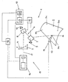
- scanner welding To create the workpiece 2 are four welding points at the processing points 3a, 3b, 3c, 3d.
- the laser processing beam 4 is generated in a CO 2 laser, not shown, and guided for workpiece machining via a partially transparent mirror 5 and a scanner optics 6 to the workpiece 2.
- Other types of lasers such as YAG lasers, can also be used for laser beam generation.
- a perforated mirror would be conceivable.
- the scanner optics 6 is of conventional design and comprises two scanner mirrors 7, 8. These are movable about adjusting axes 9, 10 and thus adjustable. The adjustment of the scanner mirrors 7, 8 or of the scanner optics 6 takes place by means of an electromotive adjusting device 11, which in turn has a numerical control 12.
- the numerical control 12 of the actuator 11 Before machining the workpiece 2 with the laser processing beam 4 is the numerical control 12 of the actuator 11 to be programmed by means of a teaching device.
- a marking device in the form of a hand-held tactile pointer 13 ("Teachpointer") with a pointer mark formed by a pointer tip 14.
- the teaching device is further a device 15 for Detection of the pointer tip 14.
- the device 15 comprises a CCD camera 16 as well as other components the partially transparent Mirror 5 and scanner optics 6.
- Alternative to the CCD camera 16 could, for example, a four-quadrant diode or a PSD (Position Sensitive Detector).
- An optical axis 17 of the means 15 for detecting the Pointer point 14 is shown dotted. Between the semi-permeable Mirror 5 and the scanner optics 6 and the scanner optics 6 and the workpiece 2 fall the beam axis of the laser processing beam 4 and the optical axis 17 of the device 15 together. This circumstance is determined by the dot-dash line between the partially transmissive mirror. 5 and the pointer tip 14 illustrates. The pointer tip 14 is in a good approximation in the processing station 3a.
- An evaluation device 18 is on the one hand with the pointer 13th and on the other hand with the numerical control 12 of the actuator 11 connected.
- the connection between the evaluation device 18 and the pointer 13 is by means of a switch 19th switchable.
- the evaluation device 18 is part of the teaching device for the controller 12.
- the operator For programming the numerical control 12 of the adjusting device 11, the operator manually guides the pointer 13 at the Surface of the workpiece 2 along. At the processing points 3a, 3b, 3c, 3d, at which weld points are to be created, the operator places the pointer 13 with the pointer tip 14 to the Workpiece 2. During the movement of the pointer 13 between the processing points 3a, 3b, 3c, 3d, the pointer tip 14th by means of the CCD camera 16 via the scanner mirrors 7, 8 of the Scanner optics 6 observed. The peak recognition is done by means of Image processing. By appropriate control of the numerical Control 12 of the actuator 11 are the scanner mirrors 7, 8 automatically adjusted so that the pointer tip 14 is always displayed in the center of the picture.
- the evaluation device 18 also activated by an optical switching signal become.
- This switching signal can be, for example, by means of generate a switchable LED at the pointer tip 14. It may be from the pointer tip detection device 15 14 are detected.
- the optical activation of the evaluation device 18 is shown by the dashed line in the illustration between the CCD camera 16 and the evaluation device 18 illustrated.
- the numerical Control 12 of the adjusting device 11 via a not Connection shown coupled to the laser control.
- the laser processing beam 4 is always directed to the workpiece 2, when the scanner optics 6 is set such that the laser beam 4 at the relevant processing point 3a, 3b, 3c, 3d impinges on the workpiece 2.
Landscapes
- Physics & Mathematics (AREA)
- Optics & Photonics (AREA)
- Engineering & Computer Science (AREA)
- Plasma & Fusion (AREA)
- Mechanical Engineering (AREA)
- Laser Beam Processing (AREA)
- Mechanical Optical Scanning Systems (AREA)
- Length Measuring Devices By Optical Means (AREA)
- Numerical Control (AREA)
Abstract
Description
Claims (10)
- Vorrichtung zum Remote-Bearbeiten von Werkstücken (2) mittels eines Laserbearbeitungsstrahls (4), mit einer Scanneroptik (6), die mittels einer numerisch gesteuerten Stellvorrichtung (11) einstellbar ist, wobei der Laserbearbeitungsstrahl (4) mittels der eingestellten Scanneroptik (6) an wenigstens einer Bearbeitungsstelle (3a, 3b, 3c, 3d) auf das Werkstück (2) richtbar ist und wobei die numerische Steuerung (12) der Stellvorrichtung (11) für die Scanneroptik (6) mittels einer Teacheinrichtung programmierbar ist, dadurch gekennzeichnet, dass die Teacheinrichtungwobei mittels der Auswerteeinrichtung (18) aufgrund der Erfassung der eine Bearbeitungsstelle (3a, 3b, 3c, 3d) markierenden Zeigermarke (14) ein Einstellwert für die Steuerung (12) der Stellvorrichtung (11) für die Scanneroptik (6) definierbar ist, der in der genannten Steuerung (12) hinterlegbar ist und aufgrund dessen die Scanneroptik (6) bei der Werkstückbearbeitung derart eingestellt ist, dass sie den Laserbearbeitungsstrahl (4) auf die markierte Bearbeitungsstelle (3a, 3b, 3c, 3d) richtet.eine Markiervorrichtung in Form eines Zeigers (13) mit einer Zeigermarke (14) zum Markieren wenigstens einer Bearbeitungsstelle (3a, 3b, 3c, 3d) an dem Werkstück (2),eine Einrichtung (15) zur Erfassung der eine Bearbeitungsstelle (3a, 3b, 3c, 3d) markierenden Zeigermarke (14) sowieeine Auswerteeinrichtung (18) umfasst, die mit der Steuerung (12) der Stellvorrichtung (11) für die Scanneroptik (6) in Verbindung steht,
- Vorrichtung nach Anspruch 1, dadurch gekennzeichnet, dass die Zeigermarke (14) mittels der Einrichtung (15) zur Erfassung der eine Bearbeitungsstelle (3a, 3b, 3c, 3d) markierenden Zeigermarke (14) fortlaufend detektierbar ist und dass die Auswerteeinrichtung (18) zur Definition eines Einstellwertes für die Steuerung (12) der Stellvorrichtung (11) für die Scanneroptik (6) aktivierbar ist, sobald die Zeigermarke (14) eine Bearbeitungsstelle (3a, 3b, 3c, 3d) markiert.
- Vorrichtung nach einem der vorhergehenden Ansprüche, dadurch gekennzeichnet, dass die Auswerteeinrichtung (18) durch ein an dem Zeiger (13) generierbares Schaltsignal zur Definition eines Einstellwertes aktivierbar ist.
- Vorrichtung nach einem der vorhergehenden Ansprüche, dadurch gekennzeichnet, dass die Auswerteeinrichtung (18) durch ein an dem Zeiger (13) generierbares optisches Schaltsignal zur Definition eines Einstellwertes aktivierbar ist.
- Vorrichtung nach einem der vorhergehenden Ansprüche, dadurch gekennzeichnet, dass als Markiervorrichtung ein an das Werkstück (2) anlegbarer taktiler Zeiger (13) vorgesehen ist.
- Vorrichtung nach einem der vorhergehenden Ansprüche, dadurch gekennzeichnet, dass als Markiervorrichtung ein Lichtzeiger mit einer Zeigermarke in Form einer Lichtmarke vorgesehen ist.
- Vorrichtung nach einem der vorhergehenden Ansprüche, dadurch gekennzeichnet, dass als Einrichtung (15) zur Erfassung der eine Bearbeitungsstelle (3a, 3b, 3c, 3d) markierenden Zeigermarke (14) eine optische Einrichtung vorgesehen ist.
- Vorrichtung nach einem der vorhergehenden Ansprüche, dadurch gekennzeichnet, dass die optische Einrichtung (15) zur Erfassung der eine Bearbeitungsstelle (3a, 3b, 3c, 3d) markierenden Zeigermarke (14) als Detektor für die Zeigermarke (14) eine Kamera (16) umfasst.
- Vorrichtung nach einem der vorhergehenden Ansprüche, dadurch gekennzeichnet, dass die Scanneroptik (6) einen Teil der optischen Einrichtung (15) zur Erfassung der eine Bearbeitungsstelle (3a, 3b, 3c, 3d) markierenden Zeigermarke (14) bildet.
- Vorrichtung nach einem der vorhergehenden Ansprüche, dadurch gekennzeichnet, dass die eine Bearbeitungsstelle (3a, 3b, 3c, 3d) markierende Zeigermarke (14) mit der Bearbeitungsstelle (3a, 3b, 3c, 3d) und eine optische Achse (17) der optischen Einrichtung (15) zur Erfassung der eine Bearbeitungsstelle (3a, 3b, 3c, 3d) markierenden Zeigermarke (14) zwischen der Scanneroptik (6) und der Zeigermarke (14)/Bearbeitungsstelle (3a, 3b, 3c, 3d) mit der Strahlachse des Laserbearbeitungsstrahls (4) zusammenfallen und dass mittels der Auswerteeinrichtung (18) aufgrund der Erfassung der eine Bearbeitungsstelle (3a, 3b, 3c, 3d) markierenden Zeigermarke (14) als hinterlegbarer Einstellwert für die Steuerung (12) der Stellvorrichtung (11) für die Scanneroptik (6) der Einstellwert der genannten Steuerung (12) zum Zeitpunkt der Erfassung der eine Bearbeitungsstelle (3a, 3b, 3c, 3d) markierenden Zeigermarke (14) definierbar ist.
Priority Applications (7)
| Application Number | Priority Date | Filing Date | Title |
|---|---|---|---|
| AT03019721T ATE400394T1 (de) | 2003-08-29 | 2003-08-29 | Vorrichtung zum remote-bearbeiten von werkstücken mittels eines laserbearbeitungsstrahls |
| ES03019721T ES2309259T3 (es) | 2003-08-29 | 2003-08-29 | Dispositivo para el mecanizado remoto de piezas de trabajo mediante un rayo laser de mecanizado. |
| EP03019721A EP1510282B1 (de) | 2003-08-29 | 2003-08-29 | Vorrichtung zum Remote-Bearbeiten von Werkstücken mittels eines Laserbearbeitungsstrahls |
| DE50310111T DE50310111D1 (de) | 2003-08-29 | 2003-08-29 | Vorrichtung zum Remote-Bearbeiten von Werkstücken mittels eines Laserbearbeitungsstrahls |
| PCT/EP2004/009564 WO2005021206A1 (en) | 2003-08-29 | 2004-08-27 | Device for remote processing of workpieces using a laser processing beam |
| JP2006524333A JP2007504004A (ja) | 2003-08-29 | 2004-08-27 | レーザ加工ビームを用いてワークピースを遠隔処理する装置 |
| US11/363,544 US8084708B2 (en) | 2003-08-29 | 2006-02-24 | Remote processing of workpieces |
Applications Claiming Priority (1)
| Application Number | Priority Date | Filing Date | Title |
|---|---|---|---|
| EP03019721A EP1510282B1 (de) | 2003-08-29 | 2003-08-29 | Vorrichtung zum Remote-Bearbeiten von Werkstücken mittels eines Laserbearbeitungsstrahls |
Publications (2)
| Publication Number | Publication Date |
|---|---|
| EP1510282A1 true EP1510282A1 (de) | 2005-03-02 |
| EP1510282B1 EP1510282B1 (de) | 2008-07-09 |
Family
ID=34089639
Family Applications (1)
| Application Number | Title | Priority Date | Filing Date |
|---|---|---|---|
| EP03019721A Expired - Lifetime EP1510282B1 (de) | 2003-08-29 | 2003-08-29 | Vorrichtung zum Remote-Bearbeiten von Werkstücken mittels eines Laserbearbeitungsstrahls |
Country Status (7)
| Country | Link |
|---|---|
| US (1) | US8084708B2 (de) |
| EP (1) | EP1510282B1 (de) |
| JP (1) | JP2007504004A (de) |
| AT (1) | ATE400394T1 (de) |
| DE (1) | DE50310111D1 (de) |
| ES (1) | ES2309259T3 (de) |
| WO (1) | WO2005021206A1 (de) |
Cited By (2)
| Publication number | Priority date | Publication date | Assignee | Title |
|---|---|---|---|---|
| WO2007071736A1 (de) * | 2005-12-20 | 2007-06-28 | Technische Universität München | Verfahren und vorrichtung zum einrichten einer bahnkurve einer robotervorrichtung |
| US12235630B2 (en) | 2019-10-11 | 2025-02-25 | Panasonic Intellectual Property Management Co., Ltd. | Reading device and method to read identification signs assigned to original workpieces for a welding process |
Families Citing this family (9)
| Publication number | Priority date | Publication date | Assignee | Title |
|---|---|---|---|---|
| JP5013699B2 (ja) * | 2005-10-21 | 2012-08-29 | 株式会社キーエンス | 3次元加工データ設定装置、3次元加工データ設定方法、3次元加工データ設定プログラム、コンピュータで読み取り可能な記録媒体及び記録した機器並びにレーザ加工装置 |
| JP5132900B2 (ja) * | 2006-06-28 | 2013-01-30 | 株式会社キーエンス | レーザ加工条件設定装置、レーザ加工装置、レーザ加工条件設定方法、レーザ加工条件設定プログラム |
| JP4958489B2 (ja) * | 2006-06-30 | 2012-06-20 | 株式会社キーエンス | レーザ加工装置、レーザ加工条件設定装置、レーザ加工条件設定方法、レーザ加工条件設定プログラム |
| JP4795886B2 (ja) | 2006-07-27 | 2011-10-19 | 株式会社キーエンス | レーザ加工装置、レーザ加工条件設定装置、レーザ加工条件設定方法、レーザ加工条件設定プログラム |
| JP4956107B2 (ja) * | 2006-09-15 | 2012-06-20 | 株式会社キーエンス | レーザ加工データ生成装置、レーザ加工データ生成方法、コンピュータプログラム及びレーザマーキングシステム |
| US8923602B2 (en) * | 2008-07-22 | 2014-12-30 | Comau, Inc. | Automated guidance and recognition system and method of the same |
| JP5459255B2 (ja) * | 2011-04-08 | 2014-04-02 | 株式会社安川電機 | ロボットシステム |
| JP6348149B2 (ja) * | 2016-07-08 | 2018-06-27 | ファナック株式会社 | ロボットを用いてレーザ加工を行うレーザ加工ロボットシステム |
| JP6464213B2 (ja) * | 2017-02-09 | 2019-02-06 | ファナック株式会社 | レーザ加工ヘッドおよび撮影装置を備えるレーザ加工システム |
Citations (3)
| Publication number | Priority date | Publication date | Assignee | Title |
|---|---|---|---|---|
| US5380978A (en) * | 1991-07-12 | 1995-01-10 | Pryor; Timothy R. | Method and apparatus for assembly of car bodies and other 3-dimensional objects |
| JPH11156578A (ja) * | 1997-12-01 | 1999-06-15 | Honda Motor Co Ltd | レーザ加工装置およびレーザ加工装置における集束位置決定方法 |
| US20020162973A1 (en) * | 2001-03-29 | 2002-11-07 | Cordingley James J. | Methods and systems for processing a device, methods and systems for modeling same and the device |
Family Cites Families (22)
| Publication number | Priority date | Publication date | Assignee | Title |
|---|---|---|---|---|
| US4608651A (en) * | 1982-10-28 | 1986-08-26 | Kabushiki Kaisha Kobe Seiko Sho | Control system for direct teaching/playback type robots |
| US4825394A (en) * | 1985-05-07 | 1989-04-25 | General Dynamics Corporation | Vision metrology system |
| DE4026759A1 (de) * | 1989-09-14 | 1991-03-28 | Gen Electric | Mit schweissstossverfolgung arbeitendes laserschweisssystem |
| US5233191A (en) * | 1990-04-02 | 1993-08-03 | Hitachi, Ltd. | Method and apparatus of inspecting foreign matters during mass production start-up and mass production line in semiconductor production process |
| JP2722287B2 (ja) * | 1991-05-15 | 1998-03-04 | ファナック株式会社 | レーザセンサにおける位置検出方法 |
| JPH0534149A (ja) * | 1991-07-30 | 1993-02-09 | Mazda Motor Corp | 間隔調整用確認装置 |
| JP3010125B2 (ja) | 1994-10-25 | 2000-02-14 | イースタン技研株式会社 | 枚葉シート打抜き製造機 |
| JP2887656B2 (ja) * | 1995-03-07 | 1999-04-26 | 住友重機械工業株式会社 | レーザ加工装置 |
| US5666577A (en) * | 1995-08-31 | 1997-09-09 | Eastman Kodak Company | System for switching pointing indices in laser aimed cameras |
| US5727433A (en) * | 1995-09-08 | 1998-03-17 | Gerber Garment Technology, Inc. | Method for cutting sheet material |
| US5932119A (en) * | 1996-01-05 | 1999-08-03 | Lazare Kaplan International, Inc. | Laser marking system |
| JPH10240332A (ja) * | 1997-02-21 | 1998-09-11 | Mitsubishi Heavy Ind Ltd | ロボット教示器 |
| JP3269005B2 (ja) * | 1997-05-12 | 2002-03-25 | 川崎重工業株式会社 | ロボット制御装置 |
| JP3984683B2 (ja) * | 1997-05-29 | 2007-10-03 | 芝浦メカトロニクス株式会社 | レーザ加工装置および加工対象物の位置測定方法 |
| US6091074A (en) * | 1998-05-11 | 2000-07-18 | Astroterra Corporation | System for directing a laser beam toward an active area |
| US6536553B1 (en) * | 2000-04-25 | 2003-03-25 | The United States Of America As Represented By The Secretary Of The Army | Method and apparatus using acoustic sensor for sub-surface object detection and visualization |
| JP3394750B2 (ja) * | 2000-10-02 | 2003-04-07 | ファナック株式会社 | ワーク押し付け装置 |
| JP2002137081A (ja) * | 2000-10-26 | 2002-05-14 | Sunx Ltd | レーザーマーキング装置 |
| CN1261275C (zh) * | 2001-09-28 | 2006-06-28 | 三菱电机株式会社 | 三维激光加工机 |
| US7067763B2 (en) * | 2002-05-17 | 2006-06-27 | Gsi Group Corporation | High speed, laser-based marking method and system for producing machine readable marks on workpieces and semiconductor devices with reduced subsurface damage produced thereby |
| EP2012221A3 (de) * | 2002-11-20 | 2009-05-13 | Koninklijke Philips Electronics N.V. | Benutzerschnittstellensystem auf der basis eines zeigegeräts |
| US7038661B2 (en) * | 2003-06-13 | 2006-05-02 | Microsoft Corporation | Pointing device and cursor for use in intelligent computing environments |
-
2003
- 2003-08-29 DE DE50310111T patent/DE50310111D1/de not_active Expired - Lifetime
- 2003-08-29 EP EP03019721A patent/EP1510282B1/de not_active Expired - Lifetime
- 2003-08-29 ES ES03019721T patent/ES2309259T3/es not_active Expired - Lifetime
- 2003-08-29 AT AT03019721T patent/ATE400394T1/de not_active IP Right Cessation
-
2004
- 2004-08-27 WO PCT/EP2004/009564 patent/WO2005021206A1/en not_active Ceased
- 2004-08-27 JP JP2006524333A patent/JP2007504004A/ja active Pending
-
2006
- 2006-02-24 US US11/363,544 patent/US8084708B2/en not_active Expired - Fee Related
Patent Citations (3)
| Publication number | Priority date | Publication date | Assignee | Title |
|---|---|---|---|---|
| US5380978A (en) * | 1991-07-12 | 1995-01-10 | Pryor; Timothy R. | Method and apparatus for assembly of car bodies and other 3-dimensional objects |
| JPH11156578A (ja) * | 1997-12-01 | 1999-06-15 | Honda Motor Co Ltd | レーザ加工装置およびレーザ加工装置における集束位置決定方法 |
| US20020162973A1 (en) * | 2001-03-29 | 2002-11-07 | Cordingley James J. | Methods and systems for processing a device, methods and systems for modeling same and the device |
Non-Patent Citations (1)
| Title |
|---|
| PATENT ABSTRACTS OF JAPAN vol. 1999, no. 11 30 September 1999 (1999-09-30) * |
Cited By (2)
| Publication number | Priority date | Publication date | Assignee | Title |
|---|---|---|---|---|
| WO2007071736A1 (de) * | 2005-12-20 | 2007-06-28 | Technische Universität München | Verfahren und vorrichtung zum einrichten einer bahnkurve einer robotervorrichtung |
| US12235630B2 (en) | 2019-10-11 | 2025-02-25 | Panasonic Intellectual Property Management Co., Ltd. | Reading device and method to read identification signs assigned to original workpieces for a welding process |
Also Published As
| Publication number | Publication date |
|---|---|
| US8084708B2 (en) | 2011-12-27 |
| US20060180582A1 (en) | 2006-08-17 |
| EP1510282B1 (de) | 2008-07-09 |
| ES2309259T3 (es) | 2008-12-16 |
| DE50310111D1 (de) | 2008-08-21 |
| ATE400394T1 (de) | 2008-07-15 |
| JP2007504004A (ja) | 2007-03-01 |
| WO2005021206A1 (en) | 2005-03-10 |
Similar Documents
| Publication | Publication Date | Title |
|---|---|---|
| AT517185B1 (de) | Verfahren zum Gravieren, Markieren und/oder Beschriften eines Werkstückes () mit einem | |
| DE102018102333B4 (de) | Laserbearbeitungssystem mit laserbearbeitungskopf und abbildungsvorrichtung | |
| DE102017115922B4 (de) | Verfahren und Vorrichtung zur Messung und Einstellung eines Abstands zwischen einem Bearbeitungskopf und einem Werkstück sowie dazugehöriges Verfahren zur Regelung | |
| DE102006030130B3 (de) | Verfahren und Vorrichtung zum Bearbeiten eines Werkstücks mittels eines Energiestrahls, insbesondere Laserstrahls | |
| EP0520396B1 (de) | Automatische Werkzeugvermessung | |
| EP0707920A2 (de) | Kompakter Laserbearbeitungskopf zur Lasermaterialbearbeitung mit integrierter on-line-Bahnkontrolle | |
| WO2012163545A1 (de) | Verfahren zum überwachen der bearbeitung sowie vorrichtung zum bearbeiten eines werkstücks mit einem hochenergetischen bearbeitungsstrahl | |
| DE102005060967A1 (de) | Verfahren und Vorrichtung zum Einrichten einer Bahnkurve einer Robotervorrichtung | |
| DE102011009345B3 (de) | Verfahren und Vorrichtung zur Erfassung einer Partikeldichteverteilung im Strahl einer Düse | |
| WO2009083122A1 (de) | Verfahren zum herstellen eines dreidimensionalen objekts | |
| EP1510282B1 (de) | Vorrichtung zum Remote-Bearbeiten von Werkstücken mittels eines Laserbearbeitungsstrahls | |
| DE102010005896A1 (de) | Laserschweißroboter und -verfahren sowie damit hergestelltes Bauteil | |
| EP3225322B1 (de) | Verfahren und biegemaschine zur herstellung eines mehrdimensional gebogenen biegeteils | |
| EP1640101A2 (de) | Verfahren und Vorrichtung zur Regelung eines automatischen Bearbeitungsprozesses | |
| AT515839A1 (de) | Verfahren und Einrichtung zum Bearbeiten von Werkstücken | |
| EP3528993A1 (de) | Bild-basierte technologiewahl beim laserschweissen | |
| DE102018217940A1 (de) | Verfahren und Bearbeitungsmaschine zum Bearbeiten eines Werkstücks | |
| DE202012012817U1 (de) | Mehrachsroboter zur Laserbearbeitung von Werkstücken | |
| EP2091699A2 (de) | Verfahren und vorrichtung zur feinpositionierung eines werkzeugs mit einer handhabungseinrichtung | |
| EP4408604B1 (de) | Verfahren zum ermitteln einer position eines werkstücks in einem bearbeitungsraum eines laserplotter zum schneiden, gravieren, markieren und/oder beschriften des werkstückes, sowie verfahren zum kalibrieren und laserplotter hierfür | |
| DE102018124208A1 (de) | Verfahren und Vorrichtung zur Überwachung eines Bearbeitungsprozesses eines Werkstücks mittels eines Laserstrahls | |
| DE102015115803A1 (de) | Verfahren zum Führen eines Bearbeitungskopfes entlang einer zu bearbeitenden Spur | |
| DE102005045854B3 (de) | Verfahren und System zur Kalibrierung einer Kamera in Produktionsmaschinen | |
| EP2288463B1 (de) | Verfahren zum betrieb einer stichsäge. | |
| DE102004001168A1 (de) | Verfahren und Vorrichtung zur Nahtführung beim Laserschweissen |
Legal Events
| Date | Code | Title | Description |
|---|---|---|---|
| PUAI | Public reference made under article 153(3) epc to a published international application that has entered the european phase |
Free format text: ORIGINAL CODE: 0009012 |
|
| AK | Designated contracting states |
Kind code of ref document: A1 Designated state(s): AT BE BG CH CY CZ DE DK EE ES FI FR GB GR HU IE IT LI LU MC NL PT RO SE SI SK TR |
|
| AX | Request for extension of the european patent |
Extension state: AL LT LV MK |
|
| 17P | Request for examination filed |
Effective date: 20050810 |
|
| AKX | Designation fees paid |
Designated state(s): AT BE BG CH CY CZ DE DK EE ES FI FR GB GR HU IE IT LI LU MC NL PT RO SE SI SK TR |
|
| GRAP | Despatch of communication of intention to grant a patent |
Free format text: ORIGINAL CODE: EPIDOSNIGR1 |
|
| GRAS | Grant fee paid |
Free format text: ORIGINAL CODE: EPIDOSNIGR3 |
|
| GRAA | (expected) grant |
Free format text: ORIGINAL CODE: 0009210 |
|
| AK | Designated contracting states |
Kind code of ref document: B1 Designated state(s): AT BE BG CH CY CZ DE DK EE ES FI FR GB GR HU IE IT LI LU MC NL PT RO SE SI SK TR |
|
| REG | Reference to a national code |
Ref country code: GB Ref legal event code: FG4D Free format text: NOT ENGLISH |
|
| RIN1 | Information on inventor provided before grant (corrected) |
Inventor name: KAUPP, PETER Inventor name: ANDREASCH, WOLFGANG Inventor name: HORN, ARMIN |
|
| REG | Reference to a national code |
Ref country code: CH Ref legal event code: EP |
|
| REF | Corresponds to: |
Ref document number: 50310111 Country of ref document: DE Date of ref document: 20080821 Kind code of ref document: P |
|
| REG | Reference to a national code |
Ref country code: IE Ref legal event code: FG4D Free format text: LANGUAGE OF EP DOCUMENT: GERMAN |
|
| PGFP | Annual fee paid to national office [announced via postgrant information from national office to epo] |
Ref country code: ES Payment date: 20080828 Year of fee payment: 6 |
|
| REG | Reference to a national code |
Ref country code: ES Ref legal event code: FG2A Ref document number: 2309259 Country of ref document: ES Kind code of ref document: T3 |
|
| NLV1 | Nl: lapsed or annulled due to failure to fulfill the requirements of art. 29p and 29m of the patents act | ||
| PG25 | Lapsed in a contracting state [announced via postgrant information from national office to epo] |
Ref country code: NL Free format text: LAPSE BECAUSE OF FAILURE TO SUBMIT A TRANSLATION OF THE DESCRIPTION OR TO PAY THE FEE WITHIN THE PRESCRIBED TIME-LIMIT Effective date: 20080709 Ref country code: PT Free format text: LAPSE BECAUSE OF FAILURE TO SUBMIT A TRANSLATION OF THE DESCRIPTION OR TO PAY THE FEE WITHIN THE PRESCRIBED TIME-LIMIT Effective date: 20081209 |
|
| PG25 | Lapsed in a contracting state [announced via postgrant information from national office to epo] |
Ref country code: SI Free format text: LAPSE BECAUSE OF FAILURE TO SUBMIT A TRANSLATION OF THE DESCRIPTION OR TO PAY THE FEE WITHIN THE PRESCRIBED TIME-LIMIT Effective date: 20080709 Ref country code: FI Free format text: LAPSE BECAUSE OF FAILURE TO SUBMIT A TRANSLATION OF THE DESCRIPTION OR TO PAY THE FEE WITHIN THE PRESCRIBED TIME-LIMIT Effective date: 20080709 Ref country code: BG Free format text: LAPSE BECAUSE OF FAILURE TO SUBMIT A TRANSLATION OF THE DESCRIPTION OR TO PAY THE FEE WITHIN THE PRESCRIBED TIME-LIMIT Effective date: 20081009 |
|
| REG | Reference to a national code |
Ref country code: IE Ref legal event code: FD4D |
|
| PG25 | Lapsed in a contracting state [announced via postgrant information from national office to epo] |
Ref country code: MC Free format text: LAPSE BECAUSE OF NON-PAYMENT OF DUE FEES Effective date: 20080831 |
|
| REG | Reference to a national code |
Ref country code: CH Ref legal event code: PL |
|
| PG25 | Lapsed in a contracting state [announced via postgrant information from national office to epo] |
Ref country code: EE Free format text: LAPSE BECAUSE OF FAILURE TO SUBMIT A TRANSLATION OF THE DESCRIPTION OR TO PAY THE FEE WITHIN THE PRESCRIBED TIME-LIMIT Effective date: 20080709 Ref country code: DK Free format text: LAPSE BECAUSE OF FAILURE TO SUBMIT A TRANSLATION OF THE DESCRIPTION OR TO PAY THE FEE WITHIN THE PRESCRIBED TIME-LIMIT Effective date: 20080709 Ref country code: IE Free format text: LAPSE BECAUSE OF FAILURE TO SUBMIT A TRANSLATION OF THE DESCRIPTION OR TO PAY THE FEE WITHIN THE PRESCRIBED TIME-LIMIT Effective date: 20080709 |
|
| PLBE | No opposition filed within time limit |
Free format text: ORIGINAL CODE: 0009261 |
|
| STAA | Information on the status of an ep patent application or granted ep patent |
Free format text: STATUS: NO OPPOSITION FILED WITHIN TIME LIMIT |
|
| PG25 | Lapsed in a contracting state [announced via postgrant information from national office to epo] |
Ref country code: SK Free format text: LAPSE BECAUSE OF FAILURE TO SUBMIT A TRANSLATION OF THE DESCRIPTION OR TO PAY THE FEE WITHIN THE PRESCRIBED TIME-LIMIT Effective date: 20080709 Ref country code: RO Free format text: LAPSE BECAUSE OF FAILURE TO SUBMIT A TRANSLATION OF THE DESCRIPTION OR TO PAY THE FEE WITHIN THE PRESCRIBED TIME-LIMIT Effective date: 20080709 |
|
| 26N | No opposition filed |
Effective date: 20090414 |
|
| GBPC | Gb: european patent ceased through non-payment of renewal fee |
Effective date: 20081009 |
|
| PG25 | Lapsed in a contracting state [announced via postgrant information from national office to epo] |
Ref country code: LI Free format text: LAPSE BECAUSE OF NON-PAYMENT OF DUE FEES Effective date: 20080831 Ref country code: CH Free format text: LAPSE BECAUSE OF NON-PAYMENT OF DUE FEES Effective date: 20080831 |
|
| PG25 | Lapsed in a contracting state [announced via postgrant information from national office to epo] |
Ref country code: BE Free format text: LAPSE BECAUSE OF NON-PAYMENT OF DUE FEES Effective date: 20080831 |
|
| PG25 | Lapsed in a contracting state [announced via postgrant information from national office to epo] |
Ref country code: AT Free format text: LAPSE BECAUSE OF NON-PAYMENT OF DUE FEES Effective date: 20080829 |
|
| PG25 | Lapsed in a contracting state [announced via postgrant information from national office to epo] |
Ref country code: GB Free format text: LAPSE BECAUSE OF NON-PAYMENT OF DUE FEES Effective date: 20081009 |
|
| PG25 | Lapsed in a contracting state [announced via postgrant information from national office to epo] |
Ref country code: SE Free format text: LAPSE BECAUSE OF FAILURE TO SUBMIT A TRANSLATION OF THE DESCRIPTION OR TO PAY THE FEE WITHIN THE PRESCRIBED TIME-LIMIT Effective date: 20081009 |
|
| PG25 | Lapsed in a contracting state [announced via postgrant information from national office to epo] |
Ref country code: CY Free format text: LAPSE BECAUSE OF FAILURE TO SUBMIT A TRANSLATION OF THE DESCRIPTION OR TO PAY THE FEE WITHIN THE PRESCRIBED TIME-LIMIT Effective date: 20080709 Ref country code: HU Free format text: LAPSE BECAUSE OF FAILURE TO SUBMIT A TRANSLATION OF THE DESCRIPTION OR TO PAY THE FEE WITHIN THE PRESCRIBED TIME-LIMIT Effective date: 20090110 Ref country code: LU Free format text: LAPSE BECAUSE OF NON-PAYMENT OF DUE FEES Effective date: 20080829 |
|
| REG | Reference to a national code |
Ref country code: ES Ref legal event code: FD2A Effective date: 20090831 |
|
| PG25 | Lapsed in a contracting state [announced via postgrant information from national office to epo] |
Ref country code: GR Free format text: LAPSE BECAUSE OF FAILURE TO SUBMIT A TRANSLATION OF THE DESCRIPTION OR TO PAY THE FEE WITHIN THE PRESCRIBED TIME-LIMIT Effective date: 20081010 |
|
| PG25 | Lapsed in a contracting state [announced via postgrant information from national office to epo] |
Ref country code: ES Free format text: LAPSE BECAUSE OF NON-PAYMENT OF DUE FEES Effective date: 20090830 |
|
| PGFP | Annual fee paid to national office [announced via postgrant information from national office to epo] |
Ref country code: TR Payment date: 20080821 Year of fee payment: 6 |
|
| PG25 | Lapsed in a contracting state [announced via postgrant information from national office to epo] |
Ref country code: TR Free format text: LAPSE BECAUSE OF NON-PAYMENT OF DUE FEES Effective date: 20090829 |
|
| REG | Reference to a national code |
Ref country code: FR Ref legal event code: PLFP Year of fee payment: 14 |
|
| REG | Reference to a national code |
Ref country code: FR Ref legal event code: PLFP Year of fee payment: 15 |
|
| REG | Reference to a national code |
Ref country code: FR Ref legal event code: PLFP Year of fee payment: 16 |
|
| PGFP | Annual fee paid to national office [announced via postgrant information from national office to epo] |
Ref country code: DE Payment date: 20200819 Year of fee payment: 18 Ref country code: FR Payment date: 20200821 Year of fee payment: 18 Ref country code: CZ Payment date: 20200828 Year of fee payment: 18 |
|
| PGFP | Annual fee paid to national office [announced via postgrant information from national office to epo] |
Ref country code: IT Payment date: 20200826 Year of fee payment: 18 |
|
| REG | Reference to a national code |
Ref country code: DE Ref legal event code: R119 Ref document number: 50310111 Country of ref document: DE |
|
| PG25 | Lapsed in a contracting state [announced via postgrant information from national office to epo] |
Ref country code: CZ Free format text: LAPSE BECAUSE OF NON-PAYMENT OF DUE FEES Effective date: 20210829 |
|
| PG25 | Lapsed in a contracting state [announced via postgrant information from national office to epo] |
Ref country code: IT Free format text: LAPSE BECAUSE OF NON-PAYMENT OF DUE FEES Effective date: 20210829 Ref country code: FR Free format text: LAPSE BECAUSE OF NON-PAYMENT OF DUE FEES Effective date: 20210831 Ref country code: DE Free format text: LAPSE BECAUSE OF NON-PAYMENT OF DUE FEES Effective date: 20220301 |