EP1509727B1 - Bride pour l'observation d'une flamme - Google Patents
Bride pour l'observation d'une flamme Download PDFInfo
- Publication number
- EP1509727B1 EP1509727B1 EP03735711A EP03735711A EP1509727B1 EP 1509727 B1 EP1509727 B1 EP 1509727B1 EP 03735711 A EP03735711 A EP 03735711A EP 03735711 A EP03735711 A EP 03735711A EP 1509727 B1 EP1509727 B1 EP 1509727B1
- Authority
- EP
- European Patent Office
- Prior art keywords
- flange
- observation
- flame
- intermediate space
- bore
- Prior art date
- Legal status (The legal status is an assumption and is not a legal conclusion. Google has not performed a legal analysis and makes no representation as to the accuracy of the status listed.)
- Expired - Lifetime
Links
Images
Classifications
-
- F—MECHANICAL ENGINEERING; LIGHTING; HEATING; WEAPONS; BLASTING
- F23—COMBUSTION APPARATUS; COMBUSTION PROCESSES
- F23M—CASINGS, LININGS, WALLS OR DOORS SPECIALLY ADAPTED FOR COMBUSTION CHAMBERS, e.g. FIREBRIDGES; DEVICES FOR DEFLECTING AIR, FLAMES OR COMBUSTION PRODUCTS IN COMBUSTION CHAMBERS; SAFETY ARRANGEMENTS SPECIALLY ADAPTED FOR COMBUSTION APPARATUS; DETAILS OF COMBUSTION CHAMBERS, NOT OTHERWISE PROVIDED FOR
- F23M11/00—Safety arrangements
- F23M11/04—Means for supervising combustion, e.g. windows
- F23M11/042—Viewing ports of windows
Definitions
- the present invention relates to a flange for optical flame observation in a gas turbine.
- the flange in this case comprises at least one bore for optical observation, in which bore at least one disc is arranged to the flame-side space, which is in substantially immediate connection with a combustion chamber in which the observable at least one flame is arranged, from the outer space from which the observation of the at least one flame can take place.
- the flames in the combustion chamber of a gas turbine must be monitored and monitored. This happens inter alia in Ringbrennkammem, in which to some extent a single, circumferential, of a plurality of on the circumference arranged burner supplied flame is present, for example, by at least one observation tube is passed through the housing of the gas turbine to the outside of the gas turbine.
- the tube leads through arranged in the housing cavities, which serve, for example, the supply of cooling air, additional combustion air or the inclusion of fuel supply lines, etc.
- the tube is usually open to the combustion chamber, that is, in the pipe usually there is a pressure which substantially corresponds to the pressure in the combustion chamber, and a temperature which is also in the region of the temperature in the combustion chamber, but due to the weak convection in the pipe with respect to the temperature sets a decreasing gradient towards the outside of the gas turbine.
- monitoring means in the form of flame detectors with optical detectors are arranged, which allow an automated and continuous observation and control of the flame activity.
- These monitoring means are arranged outside the gas turbine, that is, essentially at room temperature and normal pressure, this on the one hand, so as not to overburden these observation means thermally and mechanically, and to replace them on the other hand easier and wait.
- at least one suitable i. E.
- the optical path of the flame observation not impairing disc provided, which is inserted either at the end of the observation tube or in a patch on the observation tube flange.
- the at least one disc is installed in the flange for this purpose, ie. z. B. welded in the flange.
- the present invention is therefore based on the object to provide a flange with at least one recessed disc available which z.
- the flange proposed according to the invention is characterized in that, with respect to the optical axis one behind the other, preferably parallel and perpendicular to the optical axis, two discs are arranged, which delimit a sealed space in the bore, and means for dehumidifying the sealed gap are arranged are.
- the arrangement of two slices in succession has the advantage that it creates a redundant system.
- the presence of two slices one behind the other results in increased safety, since advantageously each slice alone is able to withstand the entire temperature and pressure difference between the outside environment and the inside of the observation tube.
- a defect in one of the two discs does not directly lead to a failure of the gas turbine (which at an open connection between the combustion chamber and
- the means are accordingly designed in the form of at least one drying cartridge.
- the drying cartridge can then be arranged in accordance with the flange in an area which is in communication with the gap between the two discs, so that a dehumidification of this gap is ensured. It is also possible to arrange the drying cartridge directly in the intermediate space, provided that the optical path for observation is not disturbed.
- Particularly suitable as dry cartridges are products which can be used for dehumidification after absorption of moisture by simply baking. This usually involves hygroscopic substances stored, for example, in a porous aluminum container, which have the property of releasing the absorbed water again when an elevated temperature is applied. Thus, such dry cartridges after absorption of moisture can be simply dried in an oven by heating again, and then in turn be used to dehumidify the gap.
- the dehumidifying means are arranged in the flange so that they can be used, replaced or removed from the outside of the flange facing away from the intermediate space.
- This arrangement z. B. a dry cartridge in the flange allows replacement of these dehumidifying, without one of the two successive discs must be removed from the flange. Maintenance of the flange becomes particularly easy and efficient. Preference is given here so that at least one, with respect to the optical axis arranged laterally to the gap cavity for the means for dehumidification is provided, which is in communication with the gap, said compound in particular via at least one opening between the cavity and the gap is ensured.
- the flange has at least one hole arranged substantially perpendicular to the optical axis, which hole communicates with the gap via at least one opening, which hole provides a cavity for receiving the means , And which can be sealed to the outside of the flange via closure means, in particular in the form of a seal screw.
- the hole may have an arbitrary cross-section, but advantageously it is cylindrically shaped (with the diameter being particularly preferably reduced shortly before the intermediate space, so that the cartridge is held in the region of large diameter without falling into the intermediate space), and his the space remote from the area provided with an internal thread so that z.
- a sealing screw (optionally provided with sealing rings) allows easy sealing of this hole after insertion of the drying agent.
- observation-side disc can be inserted, replaced, or removed from the observation-side end of the flange, and / or that the flame-side disc can be inserted, exchanged, or removed from the flame-side end of the flange ,
- This simple interchangeability of the discs from the respective side also ensures a simple and associated with little effort maintenance of the observation flange.
- the discs can be simply taken out or cleaned in case of breakage or contamination.
- the mechanical design of the interchangeability of the two sides is designed identically, so that both the two discs and their attachment means in the flange are identical and thus present as few different parts as possible.
- grub screws are advantageously used with a central bore, that is, at least one of the discs is held at least one grub screw with external thread and axial hole from the side facing away from the gap in a flange disposed inside thread. It also proves to be advantageous to provide second means available, which a Fixation of the grub screw in relation to their rotation in the internal thread allowed. This, in order to prevent the vibration occurring in gas turbines, that I solve the grub screws during operation, and thus the tightness of the gap can be reduced due to relaxation of the contact pressure of the discs. Usually, the tightness on the side facing the gap of the discs is ensured by sealing rings (O-rings). Also on the grub screw side facing sealing rings may be arranged, optionally in combination with a washer.
- a preferred embodiment of the grub screw is characterized in that it has on the side facing away from the disc at least one, substantially parallel to the optical axis and laterally offset to this arranged bore, in particular in the form of a blind hole, and that the flange on the corresponding End side at least one, in addition substantially parallel, with respect to the optical axis axially outside the internal thread arranged bore, in particular in the form of a blind hole, wherein the fixing of the grub screw can be done via a protruding into the two holes mounting bracket.
- the mounting bracket which z. B. can be easily realized by a U-shaped wire is so easy and to some extent automatically fixed by firing the flange on the housing and / or observation tube combustion chamber side, respectively equally by the attachment of an observation means on the outside.
- Another preferred embodiment is characterized in that the observation of the flame via a flame detector with optical detector, and in particular the flange is struck on the housing of a gas turbine via a flange plate, wherein the observation of the at least one flame in the combustion chamber of the gas turbine via a Observation tube takes place, which projects through the housing of the gas turbine on the optical axis to the combustion chamber and thus connects the combustion chamber via the interior of the observation tube.
- Yet another preferred embodiment of the invention comprises disks of quartz glass having a thickness in the range of 0.5 to 2 cm, in particular in the range of 1 cm, wherein the discs have a diameter of in the range of 1.5 to 4 cm, in particular in the range of 3 cm.
- the two slices are advantageously in the A range of 2 to 10 cm, in particular in the range of 3 to 5 cm apart from each other along the optical axis, and there are provided in the direction of the gap and / or to the gap facing away from the fastening means seals, in particular in the form of Teflon or graphite gaskets.
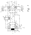
- FIG. 1 shows an observation flange, which is to serve as an embodiment of the present invention.
- the flange 1 has a flange plate 2, via which the observation flange can be struck against a housing 4 of a gas turbine.
- the flange plate 2 is provided with holes through which corresponding fastening screws 3 can be guided and screwed to the housing 4.
- the flange 1 has a body which is cylindrical in this case, wherein the body tapers between the housing 4 remote from the part 4 and the flange plate 2 in a region, so that the screws 3 can be inserted and fixed without problems.
- a flame detector 6 is arranged, which has an optical detector 7. This optical detector 7 is electronically connected directly to the control of the gas turbine, and serves to continuously monitor the flame in the combustion chamber.
- the flange 1 has a bore in its central area along the optical axis 8, which serves to observe the flame.
- this hole is cylindrical.
- the bore may also have rectangular or polygonal cross-section.
- the hole is stepped from both sides of the flange, so that the two discs 9 and 10 are inserted from both sides to a stop can. Between the stop and discs 9 and 10, a sealing ring 11 is arranged, which seals when pressed the discs 9 and 10 to the stop the interspace between the discs 22.
- the bore widens to the end of the flange on both sides subsequent to the discs 9 and 10 on, with an internal thread 15 is provided in the outermost region.
- a further seal 11 is initially arranged, and between this seal 11 and grub screw 13 respectively 14 preferably additionally a washer 12, which is intended to prevent inter alia that when screwing the grub screw of the sealing ring 11 is damaged.
- the grub screw 13 respectively 14 is cylindrical in its disk-facing portion 19, while in the outer region 20 of the inner cross-section of the grub screw 13 respectively 14 is formed polygonal or similar, so that this nut from the outside with a corresponding tool to be inserted (eg Allen key) can be easily screwed into the flange 1.
- the grub screw 13 and 14 also has one or more blind holes 17, and the flange 1 has corresponding blind holes 16 at its end faces.
- the blind holes 16 and 17 are provided to receive a mounting bracket 18, so that the mother after insertion of the mounting bracket 18 can not be rotated relative to the flange 1.
- a blind hole 16 since it is through the plurality of holes 17 in the grub screws 13, respectively. 14 is always a favorable distance to the introduction of the wire 18 without disturbing the optical axis. This fixation prevents the grub screw 13 respectively 14 in the thread 15 is released in the customary in gas turbines during operation vibrations and accordingly the seal of the discs 9 respectively 10 is no longer guaranteed in the long term.
- the flange 1 now has a substantially perpendicular to the axis 8 extending additional bore, which tapers step-like shortly before the gap 22 to a connection opening 23. Through the opening 23 of the resulting cavity in the bore 21 with the gap 22 in connection. From the transverse outer side of the flange, a drying cartridge 24 can now be introduced into this bore, and then a seal screw 25 are tightened in a corresponding provided in the bore thread 26, wherein the screw 25 seals in optionally stepped manner with sealing rings the cavity 21 to the outside ,
- the opening 23 has a diameter of 10 mm, the space 21 corresponds to a 3 ⁇ 4 "thread.
- the drying cartridge 24 is thus in operative connection with the intermediate space 22, and can thus dehumidify this intermediate space 22.
- this drying cartridge 24 can also be easily replaced or replaced, since it is easily accessible from the outside of the flange by simply screwing on the sealing screw 25 (possibly even during operation of the gas turbine).
- dry cartridges 24 are, for example, products of the type A3 Süd Chemie AG, Cologne, DE. Such cartridges are made of aluminum sheet, have a filling of about 3g molecular sieves and are regenerable. The moisture absorption is done by a non-woven disc over a hole in the bottom. They have a diameter of 23mm and a height of 11mm.
- the molecular sieves are synthetically produced zeolites.
- the water absorption is about 18 weight percent, regardless of the relative humidity.
- the regeneration temperature is between 250 and 300 degrees Celsius (the moisture stored in desiccants is released again at these temperatures).
- silica gel or blue gel would also be conceivable as a desiccant.
- such cartridges have the advantage that they can be regenerated by simple heating, and thus need not be replaced as a whole.
- the cartridges additionally have a humidity indicator, which may be inserted into the housing and which allows control or monitoring of the state of the cartridge.
- observation tubes 5 have a diameter which is usually at least as large as the bore in the region of the intermediate space 22, d. H. z. B. 3 cm.
- Such an observation tube is in direct communication with the combustion chamber (usually the observation is about 1 meter from the flame), and serves as a channel through the housing 4 of the gas turbine.
- d. H. usually pressures in the range of z. B. about 30 bar.
- a pressure in the outer region of 1 bar prevails thus at the discs a pressure difference of in the range of 29 bar.
- temperatures that are comparable to temperatures in the combustion chamber.
- the flange 1 is usually at a total temperature of over 100 degrees Celsius.
- the gaskets 11 should be made of graphite or Teflon or similar heat-resistant materials, and the disks 9 and 10 are usually formed of quartz glass having a thickness of about 1 cm. The discs are separated by about 3 cm, and have an outer diameter of about 3 cm. The diameter of the bore in the region of the intermediate space 22 is 2 cm. Order also in terms of observation redundancy and
Landscapes
- Engineering & Computer Science (AREA)
- Chemical & Material Sciences (AREA)
- Combustion & Propulsion (AREA)
- Mechanical Engineering (AREA)
- General Engineering & Computer Science (AREA)
- Investigating Or Analysing Materials By Optical Means (AREA)
- Photometry And Measurement Of Optical Pulse Characteristics (AREA)
Claims (10)
- Bride (1) pour l'observation optique d'une flamme dans une turbine à gaz, comprenant au moins un perçage pour l'observation optique, dans lequel est disposée au moins une vitre (9, 10) pour séparer l'espace côté flamme, qui est en relation essentiellement immédiate avec une chambre de combustion, dans laquelle se trouve au moins une flamme à observer, de l'espace extérieur, à partir duquel on effectue l'observation de ladite au moins une flamme, dans laquelle deux vitres (9, 10) sont disposées à distance l'une derrière l'autre par rapport à l'axe optique (8) et de préférence essentiellement perpendiculairement à celui-ci, et délimitent un espace intermédiaire étanche (22) dans le perçage, caractérisée en ce qu'elle comporte des moyens (24) pour déshumidifier l'espace intermédiaire étanche (22).
- Bride (1) selon la revendication 1, caractérisée en ce que les moyens (24) se présentent sous la forme d'au moins une cartouche de séchage (24), qui est réutilisable pour la déshumidification en particulier de préférence après reprise de l'humidité par un simple chauffage.
- Bride (1) selon l'une quelconque des revendications précédentes, caractérisée en ce que les moyens (24) sont disposés dans la bride (1) de telle manière qu'ils peuvent être introduits, remplacés ou enlevés par le côté extérieur de la bride (1) situé à l'opposé de l'espace intermédiaire (22).
- Bride (1) selon la revendication 3, caractérisée en ce qu'elle comporte au moins un espace creux (21) pour les moyens (24) de déshumidification, disposé latéralement à l'espace intermédiaire (22) par rapport à l'axe optique (8), et qui est en communication avec l'espace intermédiaire (22), cette communication étant garantie en particulier par au moins une ouverture (23) entre l'espace creux (21) et l'espace intermédiaire (22).
- Bride (1) selon la revendication 4, caractérisée en ce que la bride (1) présente au moins un trou essentiellement perpendiculaire à l'axe optique (8), qui est en communication avec l'espace intermédiaire (22) par au moins une ouverture (23), qui présente un espace creux (21) destiné à recevoir les moyens (24), et qui peut être obturé vers le côté extérieur de la bride (1) par des moyens de fermeture, en particulier sous la forme d'une vis d'étanchéité (25).
- Bride (1) selon l'une quelconque des revendications précédentes, caractérisée en ce que la vitre côté observation (10) peut être introduite, remplacée, ou enlevée par l'extrémité de la bride (1) côté observation, et/ou en ce que la vitre côté flamme (9) peut être introduite, remplacée ou enlevée par l'extrémité de la bride (1) côté flamme.
- Bride (1) selon la revendication 6, caractérisée en ce qu'au moins une des vitres (9, 10) est maintenue par au moins une vis sans tête (13, 14) avec un filet extérieur (15) et un trou axial à partir du côté situé à l'opposé de l'espace intermédiaire (22) dans un filet intérieur (15) disposé dans la bride (1), dans laquelle il se trouve en particulier de préférence des deuxièmes moyens (16, 17, 18) qui permettent une fixation de la vis sans tête (13, 14) pour empêcher sa rotation dans le filet intérieur (15).
- Bride (1) selon la revendication 7, caractérisée en ce que la vis sans tête (13, 14) présente, sur le côté situé à l'opposé de la vitre (9, 10), au moins un perçage (17), en particulier en forme de trou borgne, essentiellement parallèle à l'axe optique (8) et décalé latéralement par rapport à celui-ci, et en ce que la bride (1) présente, sur la face frontale correspondante, un perçage (16), en particulier en forme de trou borgne, essentiellement parallèle au premier et disposé axialement à l'extérieur du filet intérieur (15) par rapport à l'axe optique (8), la fixation de la vis sans tête (13, 14) pouvant être effectuée par une attache de fixation (18) pénétrant dans les deux perçages (16, 17).
- Bride (1) selon l'une quelconque des revendications précédentes, caractérisée en ce que l'observation de la flamme est effectuée par un contrôleur de flamme (6) avec un détecteur optique (7), et en ce que notamment la bride (1) est attachée à l'enceinte d'une turbine à gaz (4) par une plaque de bride (2), dans laquelle l'observation de ladite au moins une flamme est effectuée dans la chambre de combustion de la turbine à gaz par l'intermédiaire d'un tube d'observation (5), qui pénètre jusqu'à la chambre de combustion à travers l'enceinte de la turbine à gaz (4) sur l'axe optique (8) et qui relie la chambre de combustion à celle-ci par l'espace intérieur du tube d'observation (5).
- Bride (1) selon l'une quelconque des revendications précédentes, caractérisée en ce que les vitres (9, 10) en verre de quartz présentent une épaisseur de l'ordre de 0,5 à 2 cm, en particulier de l'ordre de 1 cm, en ce qu'elles présentent un diamètre de l'ordre de 1,5 à 4 cm, en particulier de l'ordre de 3 cm, en ce que les deux vitres (9, 10) sont espacées l'une de l'autre le long de l'axe optique (8) de l'ordre de 2 à 10 cm, en particulier de l'ordre de 3 à 5 cm, et en ce que les vitres (9, 10) sont étanches en direction de l'espace intermédiaire (22) et/ou en direction des moyens de fixation (13, 14) situés à l'opposé de l'espace intermédiaire (22) avec des joints d'étanchéité (11), en particulier sous forme de joints d'étanchéité en téflon ou en graphite.
Applications Claiming Priority (3)
| Application Number | Priority Date | Filing Date | Title |
|---|---|---|---|
| CH8882002 | 2002-05-28 | ||
| CH8882002 | 2002-05-28 | ||
| PCT/EP2003/050179 WO2003100322A1 (fr) | 2002-05-28 | 2003-05-20 | Bride pour l'observation d'une flamme |
Publications (2)
| Publication Number | Publication Date |
|---|---|
| EP1509727A1 EP1509727A1 (fr) | 2005-03-02 |
| EP1509727B1 true EP1509727B1 (fr) | 2007-11-21 |
Family
ID=29555535
Family Applications (1)
| Application Number | Title | Priority Date | Filing Date |
|---|---|---|---|
| EP03735711A Expired - Lifetime EP1509727B1 (fr) | 2002-05-28 | 2003-05-20 | Bride pour l'observation d'une flamme |
Country Status (4)
| Country | Link |
|---|---|
| EP (1) | EP1509727B1 (fr) |
| AU (1) | AU2003238079A1 (fr) |
| DE (1) | DE50308651D1 (fr) |
| WO (1) | WO2003100322A1 (fr) |
Family Cites Families (4)
| Publication number | Priority date | Publication date | Assignee | Title |
|---|---|---|---|---|
| GB343580A (en) * | 1929-11-22 | 1931-02-23 | Herbert George Basil Mahon | Improvements in and relating to furnace observation windows |
| GB927646A (en) * | 1960-10-13 | 1963-05-29 | Marconi Wireless Telegraph Co | Improvements in or relating to inspection window arrangements |
| US4210120A (en) * | 1978-08-15 | 1980-07-01 | Branco Ritopecki | Furnace peep sight |
| US6024084A (en) * | 1999-02-22 | 2000-02-15 | Engineered Glass Products, Llc | Double sided heat barrier glass with clear CVD coating and method of making the same |
-
2003
- 2003-05-20 DE DE50308651T patent/DE50308651D1/de not_active Expired - Lifetime
- 2003-05-20 EP EP03735711A patent/EP1509727B1/fr not_active Expired - Lifetime
- 2003-05-20 AU AU2003238079A patent/AU2003238079A1/en not_active Abandoned
- 2003-05-20 WO PCT/EP2003/050179 patent/WO2003100322A1/fr not_active Ceased
Also Published As
| Publication number | Publication date |
|---|---|
| WO2003100322A1 (fr) | 2003-12-04 |
| EP1509727A1 (fr) | 2005-03-02 |
| DE50308651D1 (de) | 2008-01-03 |
| AU2003238079A1 (en) | 2003-12-12 |
Similar Documents
| Publication | Publication Date | Title |
|---|---|---|
| EP2046478B1 (fr) | Filtre à filetage conique | |
| EP3375968B1 (fr) | Fenêtre de visualisation pour installation rlt et boîtiers de climatisation | |
| EP0946258A1 (fr) | Recipient d'une installation de sechage par un agent d'adsorption | |
| EP2024710A1 (fr) | Protege membrane pour un capteur muni d'une membrane et capteur muni d'une membrane et protege membrane | |
| EP1509727B1 (fr) | Bride pour l'observation d'une flamme | |
| EP3701109B1 (fr) | Fenêtre d'inspection pour systèmes de cvc et chambres climatiques | |
| DE3301886C2 (de) | Vorrichtung zur Messung der Temperatur in einem mit Staub beladenen Gasstrom | |
| EP3199207A2 (fr) | Dispositif de décharge de pression, module décharge de pression et dispositif de protection contre les incendies | |
| DE69906370T2 (de) | Gastrockner | |
| EP3867567B1 (fr) | Fenêtre d'inspection pour des installations rlt et des chambres climatisées | |
| DE102012004505B3 (de) | Pyrometerrohr für eine Vakuumbehandlungsanlage sowie Vakuumbehandlungsanlage | |
| EP2593209B1 (fr) | Sécheur à adsorption compact | |
| US7240673B2 (en) | Flange for flame observation | |
| DE3702205A1 (de) | Staubdichte befestigung von filterelementen in einem filterbehaelter fuer die entstaubung von insbesondere unter hoeherem druck stehenden heissgasen | |
| EP1030289A2 (fr) | Dispositif de support pour un capteur | |
| DE2804779C3 (de) | Mehrscheiben-Drehfilter | |
| EP0104420A1 (fr) | Dispositif pour l'aération ou la ventilation de corps ou de réservoirs fermés | |
| EP0112984A1 (fr) | Galette chauffante | |
| CH624785A5 (en) | Fire detection system, in particular for a road tunnel | |
| DE4040640C2 (fr) | ||
| DE3872654T2 (de) | Ventil. | |
| AT517849B1 (de) | Kondensationspartikelzähler mit Sättigungsabschnitt | |
| EP0009628B1 (fr) | Dispositif pour la surveillance de tuyaux en matière synthétique | |
| DE1884140U (de) | Entgasungsventil. | |
| DE1607676C (de) | Vorrichtung zum Auswechseln von kastenförmigen Filterzellen bei Luftfiltern für die Abscheidung gesundheitsschädlicher Stäube |
Legal Events
| Date | Code | Title | Description |
|---|---|---|---|
| PUAI | Public reference made under article 153(3) epc to a published international application that has entered the european phase |
Free format text: ORIGINAL CODE: 0009012 |
|
| 17P | Request for examination filed |
Effective date: 20041122 |
|
| AK | Designated contracting states |
Kind code of ref document: A1 Designated state(s): AT BE BG CH CY CZ DE DK EE ES FI FR GB GR HU IE IT LI LU MC NL PT RO SE SI SK TR |
|
| AX | Request for extension of the european patent |
Extension state: AL LT LV MK |
|
| DAX | Request for extension of the european patent (deleted) | ||
| RBV | Designated contracting states (corrected) |
Designated state(s): DE GB |
|
| GRAP | Despatch of communication of intention to grant a patent |
Free format text: ORIGINAL CODE: EPIDOSNIGR1 |
|
| GRAS | Grant fee paid |
Free format text: ORIGINAL CODE: EPIDOSNIGR3 |
|
| GRAA | (expected) grant |
Free format text: ORIGINAL CODE: 0009210 |
|
| AK | Designated contracting states |
Kind code of ref document: B1 Designated state(s): DE GB |
|
| REG | Reference to a national code |
Ref country code: GB Ref legal event code: FG4D Free format text: NOT ENGLISH |
|
| REF | Corresponds to: |
Ref document number: 50308651 Country of ref document: DE Date of ref document: 20080103 Kind code of ref document: P |
|
| GBT | Gb: translation of ep patent filed (gb section 77(6)(a)/1977) |
Effective date: 20080206 |
|
| PLBE | No opposition filed within time limit |
Free format text: ORIGINAL CODE: 0009261 |
|
| STAA | Information on the status of an ep patent application or granted ep patent |
Free format text: STATUS: NO OPPOSITION FILED WITHIN TIME LIMIT |
|
| 26N | No opposition filed |
Effective date: 20080822 |
|
| REG | Reference to a national code |
Ref country code: DE Ref legal event code: R082 Ref document number: 50308651 Country of ref document: DE Representative=s name: ROESLER, UWE, DIPL.-PHYS.UNIV., DE Ref country code: DE Ref legal event code: R081 Ref document number: 50308651 Country of ref document: DE Owner name: GENERAL ELECTRIC TECHNOLOGY GMBH, CH Free format text: FORMER OWNER: ALSTOM TECHNOLOGY LTD., BADEN, CH Ref country code: DE Ref legal event code: R081 Ref document number: 50308651 Country of ref document: DE Owner name: ANSALDO ENERGIA SWITZERLAND AG, CH Free format text: FORMER OWNER: ALSTOM TECHNOLOGY LTD., BADEN, CH |
|
| PGFP | Annual fee paid to national office [announced via postgrant information from national office to epo] |
Ref country code: DE Payment date: 20170523 Year of fee payment: 15 Ref country code: GB Payment date: 20170519 Year of fee payment: 15 |
|
| REG | Reference to a national code |
Ref country code: GB Ref legal event code: 732E Free format text: REGISTERED BETWEEN 20170727 AND 20170802 |
|
| REG | Reference to a national code |
Ref country code: DE Ref legal event code: R082 Ref document number: 50308651 Country of ref document: DE Representative=s name: ROESLER, UWE, DIPL.-PHYS.UNIV., DE Ref country code: DE Ref legal event code: R081 Ref document number: 50308651 Country of ref document: DE Owner name: ANSALDO ENERGIA SWITZERLAND AG, CH Free format text: FORMER OWNER: GENERAL ELECTRIC TECHNOLOGY GMBH, BADEN, CH |
|
| REG | Reference to a national code |
Ref country code: DE Ref legal event code: R119 Ref document number: 50308651 Country of ref document: DE |
|
| GBPC | Gb: european patent ceased through non-payment of renewal fee |
Effective date: 20180520 |
|
| PG25 | Lapsed in a contracting state [announced via postgrant information from national office to epo] |
Ref country code: DE Free format text: LAPSE BECAUSE OF NON-PAYMENT OF DUE FEES Effective date: 20181201 Ref country code: GB Free format text: LAPSE BECAUSE OF NON-PAYMENT OF DUE FEES Effective date: 20180520 |