EP1509727B1 - Flame observation flange - Google Patents
Flame observation flange Download PDFInfo
- Publication number
- EP1509727B1 EP1509727B1 EP03735711A EP03735711A EP1509727B1 EP 1509727 B1 EP1509727 B1 EP 1509727B1 EP 03735711 A EP03735711 A EP 03735711A EP 03735711 A EP03735711 A EP 03735711A EP 1509727 B1 EP1509727 B1 EP 1509727B1
- Authority
- EP
- European Patent Office
- Prior art keywords
- flange
- observation
- flame
- intermediate space
- bore
- Prior art date
- Legal status (The legal status is an assumption and is not a legal conclusion. Google has not performed a legal analysis and makes no representation as to the accuracy of the status listed.)
- Expired - Lifetime
Links
Images
Classifications
-
- F—MECHANICAL ENGINEERING; LIGHTING; HEATING; WEAPONS; BLASTING
- F23—COMBUSTION APPARATUS; COMBUSTION PROCESSES
- F23M—CASINGS, LININGS, WALLS OR DOORS SPECIALLY ADAPTED FOR COMBUSTION CHAMBERS, e.g. FIREBRIDGES; DEVICES FOR DEFLECTING AIR, FLAMES OR COMBUSTION PRODUCTS IN COMBUSTION CHAMBERS; SAFETY ARRANGEMENTS SPECIALLY ADAPTED FOR COMBUSTION APPARATUS; DETAILS OF COMBUSTION CHAMBERS, NOT OTHERWISE PROVIDED FOR
- F23M11/00—Safety arrangements
- F23M11/04—Means for supervising combustion, e.g. windows
- F23M11/042—Viewing ports of windows
Definitions
- the present invention relates to a flange for optical flame observation in a gas turbine.
- the flange in this case comprises at least one bore for optical observation, in which bore at least one disc is arranged to the flame-side space, which is in substantially immediate connection with a combustion chamber in which the observable at least one flame is arranged, from the outer space from which the observation of the at least one flame can take place.
- the flames in the combustion chamber of a gas turbine must be monitored and monitored. This happens inter alia in Ringbrennkammem, in which to some extent a single, circumferential, of a plurality of on the circumference arranged burner supplied flame is present, for example, by at least one observation tube is passed through the housing of the gas turbine to the outside of the gas turbine.
- the tube leads through arranged in the housing cavities, which serve, for example, the supply of cooling air, additional combustion air or the inclusion of fuel supply lines, etc.
- the tube is usually open to the combustion chamber, that is, in the pipe usually there is a pressure which substantially corresponds to the pressure in the combustion chamber, and a temperature which is also in the region of the temperature in the combustion chamber, but due to the weak convection in the pipe with respect to the temperature sets a decreasing gradient towards the outside of the gas turbine.
- monitoring means in the form of flame detectors with optical detectors are arranged, which allow an automated and continuous observation and control of the flame activity.
- These monitoring means are arranged outside the gas turbine, that is, essentially at room temperature and normal pressure, this on the one hand, so as not to overburden these observation means thermally and mechanically, and to replace them on the other hand easier and wait.
- at least one suitable i. E.
- the optical path of the flame observation not impairing disc provided, which is inserted either at the end of the observation tube or in a patch on the observation tube flange.
- the at least one disc is installed in the flange for this purpose, ie. z. B. welded in the flange.
- the present invention is therefore based on the object to provide a flange with at least one recessed disc available which z.
- the flange proposed according to the invention is characterized in that, with respect to the optical axis one behind the other, preferably parallel and perpendicular to the optical axis, two discs are arranged, which delimit a sealed space in the bore, and means for dehumidifying the sealed gap are arranged are.
- the arrangement of two slices in succession has the advantage that it creates a redundant system.
- the presence of two slices one behind the other results in increased safety, since advantageously each slice alone is able to withstand the entire temperature and pressure difference between the outside environment and the inside of the observation tube.
- a defect in one of the two discs does not directly lead to a failure of the gas turbine (which at an open connection between the combustion chamber and
- the means are accordingly designed in the form of at least one drying cartridge.
- the drying cartridge can then be arranged in accordance with the flange in an area which is in communication with the gap between the two discs, so that a dehumidification of this gap is ensured. It is also possible to arrange the drying cartridge directly in the intermediate space, provided that the optical path for observation is not disturbed.
- Particularly suitable as dry cartridges are products which can be used for dehumidification after absorption of moisture by simply baking. This usually involves hygroscopic substances stored, for example, in a porous aluminum container, which have the property of releasing the absorbed water again when an elevated temperature is applied. Thus, such dry cartridges after absorption of moisture can be simply dried in an oven by heating again, and then in turn be used to dehumidify the gap.
- the dehumidifying means are arranged in the flange so that they can be used, replaced or removed from the outside of the flange facing away from the intermediate space.
- This arrangement z. B. a dry cartridge in the flange allows replacement of these dehumidifying, without one of the two successive discs must be removed from the flange. Maintenance of the flange becomes particularly easy and efficient. Preference is given here so that at least one, with respect to the optical axis arranged laterally to the gap cavity for the means for dehumidification is provided, which is in communication with the gap, said compound in particular via at least one opening between the cavity and the gap is ensured.
- the flange has at least one hole arranged substantially perpendicular to the optical axis, which hole communicates with the gap via at least one opening, which hole provides a cavity for receiving the means , And which can be sealed to the outside of the flange via closure means, in particular in the form of a seal screw.
- the hole may have an arbitrary cross-section, but advantageously it is cylindrically shaped (with the diameter being particularly preferably reduced shortly before the intermediate space, so that the cartridge is held in the region of large diameter without falling into the intermediate space), and his the space remote from the area provided with an internal thread so that z.
- a sealing screw (optionally provided with sealing rings) allows easy sealing of this hole after insertion of the drying agent.
- observation-side disc can be inserted, replaced, or removed from the observation-side end of the flange, and / or that the flame-side disc can be inserted, exchanged, or removed from the flame-side end of the flange ,
- This simple interchangeability of the discs from the respective side also ensures a simple and associated with little effort maintenance of the observation flange.
- the discs can be simply taken out or cleaned in case of breakage or contamination.
- the mechanical design of the interchangeability of the two sides is designed identically, so that both the two discs and their attachment means in the flange are identical and thus present as few different parts as possible.
- grub screws are advantageously used with a central bore, that is, at least one of the discs is held at least one grub screw with external thread and axial hole from the side facing away from the gap in a flange disposed inside thread. It also proves to be advantageous to provide second means available, which a Fixation of the grub screw in relation to their rotation in the internal thread allowed. This, in order to prevent the vibration occurring in gas turbines, that I solve the grub screws during operation, and thus the tightness of the gap can be reduced due to relaxation of the contact pressure of the discs. Usually, the tightness on the side facing the gap of the discs is ensured by sealing rings (O-rings). Also on the grub screw side facing sealing rings may be arranged, optionally in combination with a washer.
- a preferred embodiment of the grub screw is characterized in that it has on the side facing away from the disc at least one, substantially parallel to the optical axis and laterally offset to this arranged bore, in particular in the form of a blind hole, and that the flange on the corresponding End side at least one, in addition substantially parallel, with respect to the optical axis axially outside the internal thread arranged bore, in particular in the form of a blind hole, wherein the fixing of the grub screw can be done via a protruding into the two holes mounting bracket.
- the mounting bracket which z. B. can be easily realized by a U-shaped wire is so easy and to some extent automatically fixed by firing the flange on the housing and / or observation tube combustion chamber side, respectively equally by the attachment of an observation means on the outside.
- Another preferred embodiment is characterized in that the observation of the flame via a flame detector with optical detector, and in particular the flange is struck on the housing of a gas turbine via a flange plate, wherein the observation of the at least one flame in the combustion chamber of the gas turbine via a Observation tube takes place, which projects through the housing of the gas turbine on the optical axis to the combustion chamber and thus connects the combustion chamber via the interior of the observation tube.
- Yet another preferred embodiment of the invention comprises disks of quartz glass having a thickness in the range of 0.5 to 2 cm, in particular in the range of 1 cm, wherein the discs have a diameter of in the range of 1.5 to 4 cm, in particular in the range of 3 cm.
- the two slices are advantageously in the A range of 2 to 10 cm, in particular in the range of 3 to 5 cm apart from each other along the optical axis, and there are provided in the direction of the gap and / or to the gap facing away from the fastening means seals, in particular in the form of Teflon or graphite gaskets.
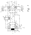
- FIG. 1 shows an observation flange, which is to serve as an embodiment of the present invention.
- the flange 1 has a flange plate 2, via which the observation flange can be struck against a housing 4 of a gas turbine.
- the flange plate 2 is provided with holes through which corresponding fastening screws 3 can be guided and screwed to the housing 4.
- the flange 1 has a body which is cylindrical in this case, wherein the body tapers between the housing 4 remote from the part 4 and the flange plate 2 in a region, so that the screws 3 can be inserted and fixed without problems.
- a flame detector 6 is arranged, which has an optical detector 7. This optical detector 7 is electronically connected directly to the control of the gas turbine, and serves to continuously monitor the flame in the combustion chamber.
- the flange 1 has a bore in its central area along the optical axis 8, which serves to observe the flame.
- this hole is cylindrical.
- the bore may also have rectangular or polygonal cross-section.
- the hole is stepped from both sides of the flange, so that the two discs 9 and 10 are inserted from both sides to a stop can. Between the stop and discs 9 and 10, a sealing ring 11 is arranged, which seals when pressed the discs 9 and 10 to the stop the interspace between the discs 22.
- the bore widens to the end of the flange on both sides subsequent to the discs 9 and 10 on, with an internal thread 15 is provided in the outermost region.
- a further seal 11 is initially arranged, and between this seal 11 and grub screw 13 respectively 14 preferably additionally a washer 12, which is intended to prevent inter alia that when screwing the grub screw of the sealing ring 11 is damaged.
- the grub screw 13 respectively 14 is cylindrical in its disk-facing portion 19, while in the outer region 20 of the inner cross-section of the grub screw 13 respectively 14 is formed polygonal or similar, so that this nut from the outside with a corresponding tool to be inserted (eg Allen key) can be easily screwed into the flange 1.
- the grub screw 13 and 14 also has one or more blind holes 17, and the flange 1 has corresponding blind holes 16 at its end faces.
- the blind holes 16 and 17 are provided to receive a mounting bracket 18, so that the mother after insertion of the mounting bracket 18 can not be rotated relative to the flange 1.
- a blind hole 16 since it is through the plurality of holes 17 in the grub screws 13, respectively. 14 is always a favorable distance to the introduction of the wire 18 without disturbing the optical axis. This fixation prevents the grub screw 13 respectively 14 in the thread 15 is released in the customary in gas turbines during operation vibrations and accordingly the seal of the discs 9 respectively 10 is no longer guaranteed in the long term.
- the flange 1 now has a substantially perpendicular to the axis 8 extending additional bore, which tapers step-like shortly before the gap 22 to a connection opening 23. Through the opening 23 of the resulting cavity in the bore 21 with the gap 22 in connection. From the transverse outer side of the flange, a drying cartridge 24 can now be introduced into this bore, and then a seal screw 25 are tightened in a corresponding provided in the bore thread 26, wherein the screw 25 seals in optionally stepped manner with sealing rings the cavity 21 to the outside ,
- the opening 23 has a diameter of 10 mm, the space 21 corresponds to a 3 ⁇ 4 "thread.
- the drying cartridge 24 is thus in operative connection with the intermediate space 22, and can thus dehumidify this intermediate space 22.
- this drying cartridge 24 can also be easily replaced or replaced, since it is easily accessible from the outside of the flange by simply screwing on the sealing screw 25 (possibly even during operation of the gas turbine).
- dry cartridges 24 are, for example, products of the type A3 Süd Chemie AG, Cologne, DE. Such cartridges are made of aluminum sheet, have a filling of about 3g molecular sieves and are regenerable. The moisture absorption is done by a non-woven disc over a hole in the bottom. They have a diameter of 23mm and a height of 11mm.
- the molecular sieves are synthetically produced zeolites.
- the water absorption is about 18 weight percent, regardless of the relative humidity.
- the regeneration temperature is between 250 and 300 degrees Celsius (the moisture stored in desiccants is released again at these temperatures).
- silica gel or blue gel would also be conceivable as a desiccant.
- such cartridges have the advantage that they can be regenerated by simple heating, and thus need not be replaced as a whole.
- the cartridges additionally have a humidity indicator, which may be inserted into the housing and which allows control or monitoring of the state of the cartridge.
- observation tubes 5 have a diameter which is usually at least as large as the bore in the region of the intermediate space 22, d. H. z. B. 3 cm.
- Such an observation tube is in direct communication with the combustion chamber (usually the observation is about 1 meter from the flame), and serves as a channel through the housing 4 of the gas turbine.
- d. H. usually pressures in the range of z. B. about 30 bar.
- a pressure in the outer region of 1 bar prevails thus at the discs a pressure difference of in the range of 29 bar.
- temperatures that are comparable to temperatures in the combustion chamber.
- the flange 1 is usually at a total temperature of over 100 degrees Celsius.
- the gaskets 11 should be made of graphite or Teflon or similar heat-resistant materials, and the disks 9 and 10 are usually formed of quartz glass having a thickness of about 1 cm. The discs are separated by about 3 cm, and have an outer diameter of about 3 cm. The diameter of the bore in the region of the intermediate space 22 is 2 cm. Order also in terms of observation redundancy and
Landscapes
- Engineering & Computer Science (AREA)
- Chemical & Material Sciences (AREA)
- Combustion & Propulsion (AREA)
- Mechanical Engineering (AREA)
- General Engineering & Computer Science (AREA)
- Investigating Or Analysing Materials By Optical Means (AREA)
- Photometry And Measurement Of Optical Pulse Characteristics (AREA)
Description
Die vorliegende Erfindung betrifft einen Flansch zur optischen Flammenbeobachtung bei einer Gasturbine. Der Flansch umfasst dabei wenigstens eine Bohrung zur optischen Beobachtung, in welcher Bohrung wenigstens eine Scheibe angeordnet ist, um den flammenseitigen Raum, welcher in im wesentlichen unmittelbarer Verbindung mit einer Brennkammer, in welcher die zu beobachtende wenigstens eine Flamme angeordnet ist, steht, vom Aussenraum, aus welchem die Beobachtung der wenigstens einen Flamme stattfinden kann, zu trennen.The present invention relates to a flange for optical flame observation in a gas turbine. The flange in this case comprises at least one bore for optical observation, in which bore at least one disc is arranged to the flame-side space, which is in substantially immediate connection with a combustion chamber in which the observable at least one flame is arranged, from the outer space from which the observation of the at least one flame can take place.
Aus Sicherheitsgründen müssen die Flammen in der Brennkammer einer Gasturbine beobachtet und überwacht werden. Dies geschieht u.a. bei Ringbrennkammem, bei welchen gewissermassen eine einzige, umlaufende, von einer Mehrzahl von auf dem Kreisumfang angeordneten Brennern versorgte Flamme vorliegt, indem zum Beispiel wenigstens ein Beobachtungsrohr durch das Gehäuse der Gasturbine zur Aussenseite der Gasturbine geführt wird. Das Rohr führt dabei durch im Gehäuse angeordnete Hohlräume, welche zum Beispiel der Zuführung von Kühlluft, zusätzlicher Verbrennungsluft oder der Aufnahme von Brennstoffzuführungsleitungen etc. dienen. Das Rohr ist dabei üblicherweise zur Brennkammer hin offen, das heisst im Rohr herrscht üblicherweise ein Druck, welcher im wesentlichen dem Druck in der Brennkammer entspricht, und eine Temperatur, welche ebenfalls in der Region der Temperatur in der Brennkammer liegt, wobei sich aber infolge der schwachen Konvektion im Rohr in Bezug auf die Temperatur ein abnehmender Gradient zur Aussenseite der Gasturbine hin einstellt.For safety reasons, the flames in the combustion chamber of a gas turbine must be monitored and monitored. This happens inter alia in Ringbrennkammem, in which to some extent a single, circumferential, of a plurality of on the circumference arranged burner supplied flame is present, for example, by at least one observation tube is passed through the housing of the gas turbine to the outside of the gas turbine. The tube leads through arranged in the housing cavities, which serve, for example, the supply of cooling air, additional combustion air or the inclusion of fuel supply lines, etc. The tube is usually open to the combustion chamber, that is, in the pipe usually there is a pressure which substantially corresponds to the pressure in the combustion chamber, and a temperature which is also in the region of the temperature in the combustion chamber, but due to the weak convection in the pipe with respect to the temperature sets a decreasing gradient towards the outside of the gas turbine.
Auf der Aussenseite der Gasturbine sind üblicherweise Beobachtungsmittel in Form von Flammenwächtern mit optischen Detektoren angeordnet, welche eine automatisierte und kontinuierliche Beobachtung und Kontrolle der Flammenaktivität erlauben. Diese Beobachtungsmittel sind dabei ausserhalb der Gasturbine angeordnet, das heisst im wesentlichen bei Raumtemperatur und Normaldruck, dies auf der einen Seite, um diese Beobachtungsmittel nicht übermässig thermisch und mechanisch zu beanspruchen, und um sie auf der anderen Seite leichter austauschen und warten zu können. Um entsprechend das Rohr zur Aussenseite, wo im wesentlichen Raumtemperatur und Normaldruck herrschen, abzudichten, ohne dabei den optischen Pfad zur Beobachtung zu beeinträchtigen, wird üblicherweise wenigstens eine geeignete, d.h. den optischen Pfad der Flammenbeobachtung nicht beeinträchtigende Scheibe vorgesehen, welche entweder am Ende des Beobachtungsrohres oder aber in einem auf das Beobachtungsrohr aufgesetzten Flansch eingesetzt ist. Infolge der hohen Temperaturdifferenzen und Druckdifferenzen zwischen dem Inneren des Beobachtungsrohres und der Umgebung der Gasturbine muss diese Scheibe hohen mechanischen Anforderungen gerecht werden und gut abgedichtet sein. Üblicherweise wird dafür die wenigstens eine Scheibe in den Flansch eingebaut, d.h. z. B. in den Flansch eingeschweisst.On the outside of the gas turbine usually monitoring means in the form of flame detectors with optical detectors are arranged, which allow an automated and continuous observation and control of the flame activity. These monitoring means are arranged outside the gas turbine, that is, essentially at room temperature and normal pressure, this on the one hand, so as not to overburden these observation means thermally and mechanically, and to replace them on the other hand easier and wait. Accordingly, in order to seal the tube to the outside, where substantially room temperature and normal pressure prevail, without impairing the optical path for observation, at least one suitable, i. E. The optical path of the flame observation not impairing disc provided, which is inserted either at the end of the observation tube or in a patch on the observation tube flange. Due to the high temperature differences and pressure differences between the interior of the observation tube and the environment of the gas turbine, this disc must meet high mechanical requirements and be well sealed. Usually, the at least one disc is installed in the flange for this purpose, ie. z. B. welded in the flange.
Beobachtungsmittel, die in Bezug auf die optische Achse hintereinander zwei Scheiben aufweisen, die einen abgedichteten Zwischenraum begrenzen, sind dem Stand der Technik bekannt (
Der vorliegenden Erfindung liegt demnach die Aufgabe zu Grunde, einen Flansch mit wenigstens einer eingelassenen Scheibe zur Verfügung zu stellen, welcher z. B. die Beobachtung von Flammen in der Brennkammer einer Gasturbine erlaubt. Es handelt sich dabei um einen Flansch zur optischen Flammenbeobachtung, umfassend wenigstens eine Bohrung zur optischen Beobachtung, in welcher Bohrung wenigstens eine Scheibe angeordnet ist, um den flammenseitigen Raum, welcher in im wesentlichen unmittelbarer Verbindung mit einer Brennkammer, in welcher die zu beobachtende wenigstens eine Flamme angeordnet ist, steht, vom Aussenraum, aus welchem die Beobachtung der wenigstens einen Flamme stattfinden kann, zu trennen.The present invention is therefore based on the object to provide a flange with at least one recessed disc available which z. B. the Observation of flames in the combustion chamber of a gas turbine allowed. It is a flange for optical flame observation, comprising at least one bore for optical observation, in which bore at least one disc is arranged around the flame-side space, which in substantially immediate connection with a combustion chamber in which the observed at least one Flame is, is to separate from the outside space, from which the observation of the at least one flame can take place.
Der erfindungsgemäss vorgeschlagene Flansch zeichnet sich nun dadurch aus, dass in Bezug auf die optische Achse hintereinander, bevorzugt parallel und senkrecht zur optischen Achse, zwei Scheiben angeordnet sind, welche einen abgedichteten Zwischenraum in der Bohrung begrenzen, und dass Mittel zur Entfeuchtung des abgedichteten Zwischenraumes angeordnet sind. Die Anordnung von zwei Scheiben hintereinander weist den Vorteil auf, dass damit ein redundantes System geschaffen wird. Mit anderen Worten ergibt sich durch das Vorhandensein von zwei Scheiben hintereinander eine erhöhte Sicherheit, da vorteilhafterweise jede Scheibe allein in der Lage ist, die gesamte Temperatur- und Druckdifferenz zwischen Aussenumgebung und dem Inneren des Beobachtungsrohres auszuhalten. Damit führt ein Defekt an einer der beiden Scheiben nicht unmittelbar zu einem Ausfall der Gasturbine (welcher bei einer offenen Verbindung zwischen Brennkammer undThe flange proposed according to the invention is characterized in that, with respect to the optical axis one behind the other, preferably parallel and perpendicular to the optical axis, two discs are arranged, which delimit a sealed space in the bore, and means for dehumidifying the sealed gap are arranged are. The arrangement of two slices in succession has the advantage that it creates a redundant system. In other words, the presence of two slices one behind the other results in increased safety, since advantageously each slice alone is able to withstand the entire temperature and pressure difference between the outside environment and the inside of the observation tube. Thus, a defect in one of the two discs does not directly lead to a failure of the gas turbine (which at an open connection between the combustion chamber and
Aussenumgebung unvermeidbar ist), da die zweite Scheibe sofort die vollständige Funktion der ersten allein übernehmen kann. Die Anordnung von zwei Scheiben hintereinander ist dabei aber insofern problematisch, als feuchte Luft, welche im Zwischenraum zwischen den beiden Scheiben eingeschlossen sein kann, die Tendenz hat, oberhalb einer gewissen Feuchtigkeit an der kalten Scheibe, das heisst an der den Beobachtungsmitteln zugewandten Scheibe, zu kondensieren. Ein Beschlagen dieser Scheibe verunmöglicht oder zumindest erschwert aber die Beobachtung der Flamme mit den Beobachtungsmitteln, da dadurch der optische Pfad wesentlich behindert und damit die Messung verfälscht wird. Dieses Problem wird erfindungsgemäss dadurch gelöst, dass Mittel zur Entfeuchtung des Zwischenraumes zwischen den beiden Scheiben vorgesehen werden. Dies kann zum Beispiel durch Anlegen eines Vakuums geschehen. Anlegen eines Vakuums weist aber den Nachteil auf, dass der Zwischenraum zwischen den beiden Scheiben äusserst gut abgedichtet sein muss, da ansonsten das Vakuum nicht langfristig gewährleistet werden kann. Dazu kommt, dass bei den üblichen Druck- und Temperaturbelastungen bei der Verwendung eines derartigen Flansches an einer Gasturbine die vollständige Dichtigkeit des Zwischenraumes nur sehr schwer gewährleistet werden kann, und dass entsprechend ein Flansch mit evakuiertem Zwischenraum häufig ausgewechselt werden muss, da eine Evakuierung vor Ort kaum möglich ist. Die kontinuierliche Entfeuchtung dieses Zwischenraumes durch Entfeuchtungsmittel anderer Art erweist sich deshalb als einfacher und sinnvoller, da im Gegensatz zu einer Evakuierung dieses Bereichs die Wartung von derartigen Entfeuchtungsmitteln wesentlich einfacher ist. Insbesondere muss so in der Regel nicht der ganze Flansch ausgewechselt werden, sondern nur die Entfeuchtungsmittel.Outside environment is unavoidable), since the second disc can immediately take over the full function of the first alone. However, the arrangement of two disks one behind the other is problematic insofar as moist air, which may be trapped in the intermediate space between the two disks, has the tendency to above a certain humidity at the cold disk, that is to say at the disk facing the observation means condense. However, fogging of this disc makes it impossible or at least makes it difficult to observe the flame with the observation means, since this significantly impedes the optical path and thus falsifies the measurement. This problem is solved according to the invention by providing means for dehumidifying the intermediate space between the two panes. This can be done for example by applying a vacuum. Applying a vacuum, however, has the disadvantage that the gap between the two discs must be sealed extremely well, otherwise the vacuum can not be guaranteed long term. In addition, in the usual pressure and temperature loads when using such Flange on a gas turbine, the complete tightness of the gap is very difficult to ensure, and that accordingly a flange with evacuated gap must be replaced frequently, since an evacuation site is hardly possible. The continuous dehumidification of this gap by dehumidifiers of other kind proves to be easier and more useful, since in contrast to an evacuation of this area, the maintenance of such dehumidifiers is much easier. In particular, it is not usually necessary to replace the entire flange, but only the dehumidifiers.
Gemäss einer ersten bevorzugten Ausführungsform der vorliegenden Erfindung werden entsprechend die Mittel in Form wenigstens einer Trockenpatrone ausgebildet. Die Trockenpatrone kann dann entsprechend im Flansch in einem Bereich angeordnet werden, welcher in Verbindung zum Zwischenraum zwischen den beiden Scheiben steht, sodass eine Entfeuchtung dieses Zwischenraumes gewährleistet ist. Es ist auch möglich, die Trockenpatrone direkt im Zwischenraum anzuordnen, sofern dadurch der optische Pfad zur Beobachtung nicht gestört wird. Ganz besonders eignen sich als Trockenpatronen Produkte, welche nach Aufnahme von Feuchtigkeit durch einfaches Ausheizen wieder zur Entfeuchtung verwendet werden können. Das handelt sich dabei üblicherweise um zum Beispiel in einem porösen Aluminiumbehälter gelagerte hygroskopische Substanzen, welche die Eigenschaft aufweisen, bei Anlegen einer erhöhten Temperatur das aufgenommene Wasser wieder freizusetzen. So können derartige Trockenpatronen nach Aufnahme von Feuchtigkeit einfach in einem Ofen durch Erhitzen wieder getrocknet werden, und anschliessend wiederum zur Entfeuchtung des Zwischenraumes verwendet werden.According to a first preferred embodiment of the present invention, the means are accordingly designed in the form of at least one drying cartridge. The drying cartridge can then be arranged in accordance with the flange in an area which is in communication with the gap between the two discs, so that a dehumidification of this gap is ensured. It is also possible to arrange the drying cartridge directly in the intermediate space, provided that the optical path for observation is not disturbed. Particularly suitable as dry cartridges are products which can be used for dehumidification after absorption of moisture by simply baking. This usually involves hygroscopic substances stored, for example, in a porous aluminum container, which have the property of releasing the absorbed water again when an elevated temperature is applied. Thus, such dry cartridges after absorption of moisture can be simply dried in an oven by heating again, and then in turn be used to dehumidify the gap.
Gemäss einer weiteren bevorzugten Ausführungsform der Erfindung sind die Entfeuchtungsmittel derart im Flansch angeordnet, dass sie von der dem Zwischenraum abgewandten Aussenseite des Flansches eingesetzt, ausgewechselt, respektive entfernt werden können. Diese Anordnung z. B. einer Trockenpatrone im Flansch ermöglicht ein Auswechseln dieser Entfeuchtungsmittel, ohne dass eine der zwei hintereinander liegenden Scheiben aus dem Flansch entfernt werden muss. Die Wartung des Flansches wird so besonders einfach und effizient. Bevorzugt geht man dabei so vor, dass wenigstens ein, in Bezug auf die optische Achse seitlich zum Zwischenraum angeordneter Hohlraum für die Mittel zur Entfeuchtung vorgesehen wird, welcher mit dem Zwischenraum in Verbindung steht, wobei diese Verbindung insbesondere über wenigstens eine Öffnung zwischen dem Hohlraum und dem Zwischenraum gewährleistet wird. Diese Anordnung erlaubt eine einfache Zugänglichkeit von der Seite des Flansches (im wesentlichen von radialer Seite in Bezug auf die optische Achse), ohne dass der optische Pfad durch die Anwesenheit der Entfeuchtungsmittel gestört wird. Weiterhin bevorzugt wird dabei die Zugänglichkeit zu den Entfeuchtungsmitteln dadurch gewährleistet, dass der Flansch wenigstens ein im wesentlichen senkrecht zur optischen Achse angeordnetes Loch aufweist, welches über wenigstens eine Öffnung mit dem Zwischenraum in Verbindung steht, welches Loch einen Hohlraum zur Aufnahme der Mittel zur Verfügung stellt, und welches zur Aussenseite des Flansches über Verschlussmittel, insbesondere in Form einer Dichtungsschraube, abgedichtet werden kann. Das Loch kann dabei einen beliebigen Querschnitt aufweisen, vorteilhafter Weise ist es aber zylindrisch ausgestaltet (wobei insbesondere bevorzugt der Durchmesser kurz vor dem Zwischenraum reduziert wird, damit die Patrone im Bereich mit grossen Durchmesser gehalten wird, ohne in den Zwischenraum zu fallen), und in seinem dem Zwischenraum abgewandten Bereich mit einem Innengewinde versehen, damit z. B. eine Dichtungsschraube (gegebenenfalls mit Dichtringen versehen) ein einfaches Abdichten dieses Loches nach Einfügen der Trocknungsmittel ermöglicht.According to a further preferred embodiment of the invention, the dehumidifying means are arranged in the flange so that they can be used, replaced or removed from the outside of the flange facing away from the intermediate space. This arrangement z. B. a dry cartridge in the flange allows replacement of these dehumidifying, without one of the two successive discs must be removed from the flange. Maintenance of the flange becomes particularly easy and efficient. Preference is given here so that at least one, with respect to the optical axis arranged laterally to the gap cavity for the means for dehumidification is provided, which is in communication with the gap, said compound in particular via at least one opening between the cavity and the gap is ensured. This arrangement allows easy access from the side of the flange (substantially from the radial side with respect to the optical axis) without disturbing the optical path by the presence of the dehumidifying means. Furthermore, the accessibility to the dehumidifying means is preferably ensured by the fact that the flange has at least one hole arranged substantially perpendicular to the optical axis, which hole communicates with the gap via at least one opening, which hole provides a cavity for receiving the means , And which can be sealed to the outside of the flange via closure means, in particular in the form of a seal screw. The hole may have an arbitrary cross-section, but advantageously it is cylindrically shaped (with the diameter being particularly preferably reduced shortly before the intermediate space, so that the cartridge is held in the region of large diameter without falling into the intermediate space), and his the space remote from the area provided with an internal thread so that z. B. a sealing screw (optionally provided with sealing rings) allows easy sealing of this hole after insertion of the drying agent.
Eine weitere bevorzugte Ausführungsform der vorliegenden Erfindung zeichnet sich dadurch aus, dass die beobachtungsseitige Scheibe vom beobachtungsseitigen Ende des Flansches eingesetzt, ausgewechselt, respektive entfernt werden kann, und/oder dass die flammenseitige Scheibe vom flammenseitigen Ende des Flansches eingesetzt, ausgewechselt, respektive entfernt werden kann. Diese einfache Auswechselbarkeit der Scheiben von der jeweiligen Seite gewährleistet ebenfalls eine einfache und mit wenig Aufwand verbundene Wartung des Beobachtungsflansches. So können die Scheiben bei einem Bruch oder bei Verschmutzung einfach herausgenommen ersetzt respektive gereinigt werden. Besonders bevorzugterweise wird dabei die mechanische Gestaltung der Auswechselbarkeit von den beiden Seiten identisch gestaltet, sodass sowohl die beiden Scheiben als auch deren Befestigungsmittel im Flansch identisch sind und somit so wenig unterschiedliche Teile wie möglich vorliegen. Als Befestigungsmittel der Scheiben werden vorteilhafter Weise Madenschrauben mit einer zentralen Bohrung verwendet, das heisst wenigstens eine der Scheiben wird über wenigstens eine Madenschraube mit Aussengewinde und mit axialem Loch von der dem Zwischenraum abgewandten Seite in einem im Flansch angeordneten Innengewinde gehalten. Dabei erweist es sich ausserdem als vorteilhaft, zweite Mittel zur Verfügung zu stellen, welche eine Fixierung der Madenschraube in Bezug auf deren Rotation im Innengewinde erlaubt. Dies, um bei den bei Gasturbinen auftretenden Vibrationen zu verhindern, dass ich die Madenschrauben beim Betrieb lösen, und damit die Dichtigkeit des Zwischenraumes infolge Lockerung der Anpressung der Scheiben nachlassen kann. Üblicherweise wird dabei die Dichtigkeit auf der dem Zwischenraum zugewandten Seite der Scheiben durch Dichtringe gewährleistet (O-Ringe). Auch auf der der Madenschraube zugewandten Seite können Dichtringe angeordnet sein, gegebenenfalls in Kombination mit einer Unterlagsscheibe.Another preferred embodiment of the present invention is characterized in that the observation-side disc can be inserted, replaced, or removed from the observation-side end of the flange, and / or that the flame-side disc can be inserted, exchanged, or removed from the flame-side end of the flange , This simple interchangeability of the discs from the respective side also ensures a simple and associated with little effort maintenance of the observation flange. Thus, the discs can be simply taken out or cleaned in case of breakage or contamination. Particularly preferably, the mechanical design of the interchangeability of the two sides is designed identically, so that both the two discs and their attachment means in the flange are identical and thus present as few different parts as possible. As fastening means of the discs grub screws are advantageously used with a central bore, that is, at least one of the discs is held at least one grub screw with external thread and axial hole from the side facing away from the gap in a flange disposed inside thread. It also proves to be advantageous to provide second means available, which a Fixation of the grub screw in relation to their rotation in the internal thread allowed. This, in order to prevent the vibration occurring in gas turbines, that I solve the grub screws during operation, and thus the tightness of the gap can be reduced due to relaxation of the contact pressure of the discs. Usually, the tightness on the side facing the gap of the discs is ensured by sealing rings (O-rings). Also on the grub screw side facing sealing rings may be arranged, optionally in combination with a washer.
Eine bevorzugte Ausführungsform der Madenschraube zeichnet sich dadurch aus, dass sie auf der der Scheibe abgewandten Seite wenigstens eine, im wesentlichen parallel zur optischen Achse und seitlich zu dieser versetzt angeordnete Bohrung, insbesondere in Form eines Sackloches, aufweist, und dass der Flansch an der entsprechenden Stirnseite wenigstens eine, dazu im wesentlichen parallel verlaufende, in Bezug auf die optische Achse axial ausserhalb des Innengewindes angeordnete Bohrung, insbesondere in Form eines Sackloches, aufweist, wobei die Fixierung der Madenschraube über eine in die beiden Bohrungen ragende Befestigungsklammer erfolgen kann. Dies ist eine einfache und leicht realisierbare Ausführung der zweiten Mittel zur Fixierung. Die Befestigungsklammer, welche z. B. einfach durch einen U-förmigen Draht realisiert werden kann, wird so einfach und gewissermassen automatisch durch das Anschlagen des Flansches am Gehäuse und/oder Beobachtungsrohr brennkammerseitig fixiert, respektive gleichermassen durch das Anbringen eines Beobachtungsmittels auf der Aussenseite.A preferred embodiment of the grub screw is characterized in that it has on the side facing away from the disc at least one, substantially parallel to the optical axis and laterally offset to this arranged bore, in particular in the form of a blind hole, and that the flange on the corresponding End side at least one, in addition substantially parallel, with respect to the optical axis axially outside the internal thread arranged bore, in particular in the form of a blind hole, wherein the fixing of the grub screw can be done via a protruding into the two holes mounting bracket. This is a simple and easily realizable embodiment of the second fixing means. The mounting bracket, which z. B. can be easily realized by a U-shaped wire is so easy and to some extent automatically fixed by firing the flange on the housing and / or observation tube combustion chamber side, respectively equally by the attachment of an observation means on the outside.
Eine andere bevorzugte Ausführungsform ist dadurch gekennzeichnet, dass die Beobachtung der Flamme über einen Flammenwächter mit optischem Detektor erfolgt, und dass insbesondere der Flansch am Gehäuse einer Gasturbine über eine Flanschplatte angeschlagen ist, wobei die Beobachtung der wenigstens einen Flamme in der Brennkammer der Gasturbine über ein Beobachtungsrohr erfolgt, welches durch das Gehäuse der Gasturbine auf der optischen Achse zur Brennkammer ragt und damit die Brennkammer über den Innenraum des Beobachtungsrohres verbindet.Another preferred embodiment is characterized in that the observation of the flame via a flame detector with optical detector, and in particular the flange is struck on the housing of a gas turbine via a flange plate, wherein the observation of the at least one flame in the combustion chamber of the gas turbine via a Observation tube takes place, which projects through the housing of the gas turbine on the optical axis to the combustion chamber and thus connects the combustion chamber via the interior of the observation tube.
Eine wiederum andere bevorzugte Ausführungsform der Erfindung weist Scheiben aus Quarzglas einer Dicke im Bereich von 0,5 bis 2 cm, insbesondere im Bereich von 1 cm auf, wobei die Scheiben einen Durchmesser von im Bereich von 1,5 bis 4 cm, insbesondere im Bereich von 3 cm aufweisen. Dabei sind vorteilhafter Weise die beiden Scheiben um im Bereich von 2 bis 10 cm, insbesondere im Bereich von 3 bis 5 cm voneinander entlang der optischen Achse beabstandet, und es sind in Richtung des Zwischenraumes und/oder zu den dem Zwischenraum abgewandten Befestigungsmitteln Dichtungen vorgesehen, dies insbesondere in Form von Teflon- oder Graphit-Dichtungen.Yet another preferred embodiment of the invention comprises disks of quartz glass having a thickness in the range of 0.5 to 2 cm, in particular in the range of 1 cm, wherein the discs have a diameter of in the range of 1.5 to 4 cm, in particular in the range of 3 cm. In this case, the two slices are advantageously in the A range of 2 to 10 cm, in particular in the range of 3 to 5 cm apart from each other along the optical axis, and there are provided in the direction of the gap and / or to the gap facing away from the fastening means seals, in particular in the form of Teflon or graphite gaskets.
Weitere bevorzugte Ausführungsformen der vorliegenden Erfindung ergeben sich aus den abhängigen Ansprüchen.Further preferred embodiments of the present invention will become apparent from the dependent claims.
Die Erfindung soll nachfolgend anhand von Ausführungsbeispielen im Zusammenhang mit der Zeichnung näher erläutert werden. Es zeigt:
- Figur 1:
- einen axialen Schnitt durch einen Flansch zur Flammenbeobachtung.
- FIG. 1:
- an axial section through a flange for flame observation.
Figur 1 zeigt einen Beobachtungsflansch, welcher als Ausführungsbeispiel zur vorliegenden Erfindung dienen soll. Der Flansch 1 weist eine Flanschplatte 2 auf, über welche der Beobachtungsflansch an ein Gehäuse 4 einer Gasturbine angeschlagen werden kann. Zu diesem Zweck ist die Flanschplatte 2 mit Bohrungen versehen, durch welche entsprechende Befestigungsschrauben 3 geführt und mit dem Gehäuse 4 verschraubt werden können. Der Flansch 1 weist einen Körper auf, welcher in diesem Fall zylindrisch ausgebildet ist, wobei sich der Körper zwischen dem dem Gehäuse 4 abgewandten Teil und der Flanschplatte 2 in einem Bereich verjüngt, damit die Schrauben 3 ohne Probleme eingeführt und befestigt werden können. Auf der dem Gehäuse 4 abgewandten Seite des Flansches 1 ist ein Flammenwächter 6 angeordnet, welcher über einen optischen Detektor 7 verfügt. Dieser optische Detektor 7 wird direkt an die Steuerung der Gasturbine elektronisch angeschlossen, und dient der kontinuierlichen Überwachung der Flamme in der Brennkammer.Figure 1 shows an observation flange, which is to serve as an embodiment of the present invention. The
Der Flansch 1 weist in seinem zentralen Bereich entlang der optischen Achse 8 eine Bohrung auf, welche der Beobachtung der Flamme dient. In diesem Falle ist diese Bohrung zylindrisch ausgeführt. Die Bohrung kann aber auch rechteckigen oder vieleckigen Querschnitt aufweisen. Die Bohrung ist von beiden Seiten des Flansches gestuft ausgeführt, sodass von beiden Seiten die zwei Scheiben 9 und 10 bis zu einem Anschlag eingeschoben werden können. Zwischen Anschlag und Scheiben 9 und 10 ist ein Dichtungsring 11 angeordnet, welcher beim Anpressen der Scheiben 9 und 10 an den Anschlag den zwischen den Scheiben angeordneten Zwischenraum 22 abdichtet. Die Bohrung weitet sich zum Ende des Flansches auf beiden Seiten anschliessend an die Scheiben 9 und 10 weiter auf, wobei im äussersten Bereich ein Innengewinde 15 vorgesehen ist. In diesem aussenliegenden Bereich der Bohrung wird nun eine Madenschraube 13 respektive 14 mit zentralem Loch (damit die optische Achse nicht versperrt wird) eingeschraubt, mit welcher die jeweilige Scheibe 9 respektive 10 an den bereits genannten Anschlag gepresst wird. Zwischen Madenschraube 13 respektive 14 undThe
Scheibe 9 respektive 10 ist zunächst eine weitere Dichtung 11 angeordnet, und zwischen dieser Dichtung 11 und Madenschraube 13 respektive 14 bevorzugtermassen zusätzlich eine Unterlagsscheibe 12, welche unter anderem verhindern soll, dass beim Eindrehen der Madenschraube der Dichtungsring 11 beschädigt wird. Die Madenschraube 13 respektive 14 ist in ihrem der Scheibe zugewandten Bereich 19 zylindrisch ausgebildet, während im aussenliegenden Bereich 20 der innere Querschnitt der Madenschraube 13 respektive 14 vieleckig oder ähnlich ausgebildet ist, damit diese Mutter von aussen mit einem entsprechenden, einzuschiebenden Werkzeug (z. B. Inbusschlüssel) leicht in den Flansch 1 eingedreht werden kann. Die Madenschraube 13 respektive 14 verfügt zudem über ein oder mehrere Sacklöcher 17, und der Flansch 1 weist an seinen Stirnseiten entsprechende Sacklöcher 16 auf. Die Sacklöcher 16 und 17 sind dazu vorgesehen, eine Befestigungsklammer 18 aufzunehmen, sodass die Mutter nach Einschieben der Befestigungsklammer 18 nicht mehr gegenüber dem Flansch 1 verdreht werden kann. Üblicherweise reicht dazu ein Sackloch 16, da es durch die Vielzahl der Löcher 17 in den Madenschrauben 13 resp. 14 immer ein günstiger Abstand zum Einbringen des Drahtes 18 ohne Störung der optischen Achse gibt. Diese Fixierung verhindert, dass bei den bei Gasturbinen im Betrieb üblichen Vibrationen die Madenschraube 13 respektive 14 im Gewinde 15 gelöst wird und entsprechend auch die Dichtung der Scheiben 9 respektive 10 langfristig nicht mehr gewährleistet ist.
Diese besondere mechanische Realisierung der Befestigung der Scheiben 9 und 10 im Flansch ermöglicht nun, im Gegensatz zum im Stand der Technik üblichen Verschweissen, ein leichtes Auswechseln respektive Reinigen der Scheiben, da über ein leichtes Lösen der Madenschrauben die Scheiben aus dem Flansch herausgenommen und gereinigt respektive ersetzt werden können. Insbesondere in Kombination mit dem Mechanismus zur Fixierung der Madenschraube, welche diesen Flansch speziell für die Verwendung an Gasturbinen geeignet macht, ist diese neue Realisierung vorteilhaft.This particular mechanical realization of the attachment of the
Der Flansch 1 weist nun eine im wesentlichen senkrecht zur Achse 8 verlaufende zusätzliche Bohrung auf, welche sich kurz vor dem Zwischenraum 22 zu einer Verbindungsöffnung 23 stufenartig verjüngt. Durch die Öffnung 23 ist der in der Bohrung entstehende Hohlraum 21 mit dem Zwischenraum 22 in Verbindung. Von der transversalen Aussenseite des Flansches kann nun in diese Bohrung eine Trockenpatrone 24 eingeführt werden, und anschliessend eine Dichtungsschraube 25 in einem entsprechend in der Bohrung vorgesehenen Gewinde 26 festgedreht werden, wobei die Schraube 25 in gegebenenfalls abgestufter Weise mit Dichtringen den Hohlraum 21 nach aussen abdichtet.The
Die Öffnung 23 weist dabei einen Durchmesser von 10mm auf, der Raum 21 entspricht einem ¾" Gewinde.The
Die Trockenpatrone 24 steht damit in Wirkverbindung mit dem Zwischenraum 22, und kann so diesen Zwischenraum 22 entfeuchten. Auf der anderen Seite kann aber diese Trockenpatrone 24 auch sehr einfach ausgewechselt respektive ersetzt werden, da sie von der Aussenseite des Flansches über einfaches Aufschrauben der Dichtungsschraube 25 leicht zugänglich ist (ggf. sogar bei Betrieb der Gasturbine). Als Trockenpatronen 24 eignen sich zum Beispiel Produkte des Typs A3 der Firma Süd Chemie AG, Köln, DE. Derartige Patronen sind aus Aluminiumblech gefertigt, weisen eine Füllung aus ca. 3g Molekularsiebe auf und sind regenerierbar. Die Feuchtigkeitsaufnahme geschieht durch eine Vliessscheibe über ein Loch in der Unterseite. Sie weisen einen Durchmesser von 23mm und eine Höhe von 11mm auf. Die Molekularsiebe (M-sieves) sind synthetisch hergestellte Zeolithe. Die Wasseraufnahme beträgt ca. 18 Gewichtsprozent unabhängig von der jeweiligen relativen Feuchte. Die Regenerationstemperatur liegt zwischen 250 und 300 Grad Celsius (die in Trockenmittel gespeicherte Feuchte wird bei diesen Temperaturen wieder freigesetzt). Bei geringeren Temperaturen wäre auch Kieselgel oder Blaugel als Trockenmittel denkbar. Derartige Patronen weisen mit anderen Worten den Vorteil auf, dass sie durch einfaches Ausheizen regeneriert werden können, und so nicht als Ganzes ersetzt werden müssen. Gegebenenfalls weisen die Patronen zusätzlich einen Feuchtigkeitsanzeiger auf, welcher in das Gehäuse eingelegt sein kann und welcher eine Kontrolle respektive Überwachung des Zustands der Patrone ermöglicht.The drying
Diese Bauweise des Flansches 1 erweist sich für den Anschluss an Beobachtungsrohre 5 als geeignet. Diese Beobachtungsrohre 5 weisen einen Durchmesser auf, welcher üblicherweise wenigstens so gross ist, wie die Bohrung im Bereich des Zwischenraumes 22, d. h. z. B. 3 cm. Ein derartiges Beobachtungsrohr ist in direkter Verbindung mit der Brennkammer (üblicherweise ist dabei die Beobachtung zirka 1 Meter von der Flamme entfernt), und dient gewissermassen als Kanal durch das Gehäuse 4 der Gasturbine. Im Rohr herrschen im wesentlichen die gleichen Druckbedingungen wie in der Brennkammer, d. h. üblicherweise Drücke im Bereich von z. B. ca. 30 bar. Entsprechend einem Druck im Aussenbereich von 1 bar herrscht damit an den Scheiben eine Druckdifferenz von im Bereich von 29 bar. Ebenfalls herrschen Temperaturen, welche mit Temperaturen in der Brennkammer vergleichbar sind. Entsprechend ist der Flansch 1 bei Betrieb der Gasturbine üblicherweise auf einer Gesamttemperatur von über 100 Grad Celsius. Infolgedessen sollten die Dichtungen 11 aus Graphit oder Teflon oder ähnlichen hitzeresistenten Materialien gefertigt sein, und die Scheiben 9 und 10 sind üblicherweise aus Quarzglas mit einer Dicke von ca. 1 cm ausgebildet. Die Scheiben sind um ca. 3 cm voneinander beabstandet, und weisen einen Aussendurchmesser von ca. 3 cm auf. Der Durchmesser der Bohrung im Bereich des Zwischenraumes 22 beträgt 2 cm. Um auch in Bezug auf die Beobachtung Redundanz undThis construction of the
Vollständigkeit zu gewährleisten, werden typischerweise drei derartige Beobachtungsrohre von um den Umfang der Gasturbine verteilt.To ensure completeness, typically three such observation tubes are distributed around the circumference of the gas turbine.
- 11
- BeobachtungsflanschBeobachtungsflansch
- 22
- Flanschplatteflange
- 33
- Befestigungsschraubefixing screw
- 44
- Gehäuse der GasturbineHousing of the gas turbine
- 55
- Beobachtungsrohrobservation tube
- 66
- Flammenwächterflame detector
- 77
- optischer Detektoroptical detector
- 88th
- optischer Achse/Rotations-Achse des Flanschesoptical axis / rotation axis of the flange
- 99
- erste Scheibefirst disc
- 1010
- zweite Scheibesecond disc
- 1111
- Dichtungsringsealing ring
- 1212
- Unterlagscheibewasher
- 1313
- erste Madenschraube mit zentraler Bohrungfirst grub screw with central bore
- 1414
- zweite Madenschraube mit zentraler Bohrungsecond grub screw with central bore
- 1515
- Gewinde von 13 respektive 14Thread of 13 respectively 14
- 1616
- Bohrung im FlanschBore in the flange
- 1717
- Bohrung in MadenschraubeDrill in grub screw
- 1818
- BefestigungsklammerCrab
- 1919
- zylindrischer Teil von 13 respektive 14cylindrical part of 13 respectively 14
- 2020
- Inbus-Teil von 13 respektive 14Allen part of 13 respectively 14
- 2121
- Hohlraum für TrockenpatroneCavity for drying cartridge
- 2222
-
Zwischenraum zwischen den beiden Scheiben 9 und 10Space between the two
discs 9 and 10th - 2323
- Verbindungsöffnung zwischen 21 und 22Connection opening between 21 and 22
- 2424
- Trockenpatronedrying cartridge
- 2525
- Dichtungsschraube für TrockenpatroneSealing screw for drying cartridge
- 2626
- Gewinde von 25Thread of 25
Claims (10)
- Flange (1) for optical flame observation in a gas turbine, comprising at least one bore for optical observation, in which bore there is arranged at least one pane (9, 10) for separating the flame-side space, which is in substantially direct communication with a combustion chamber in which the at least one flame that is to be monitored is arranged, from the outside space, from which the observation of the at least one flame takes place, wherein two panes (9, 10), which delimit a sealed intermediate space (22) in the bore, are arranged spaced apart from one another and one behind the other with respect to the optical axis (8) and preferably substantially perpendicular to the latter, characterized in that means (24) for dehumidifying the sealed intermediate space (22) are provided.
- Flange (1) according to Claim 1, characterized in that the means (24) are designed in the form of at least one drying cartridge (24) which particularly preferably after the uptake of moisture can be reused for dehumidification by simply being heated up.
- Flange (1) according to one of the preceding claims, characterized in that the means (24) are arranged in such a manner in the flange (1) that they can be inserted, exchanged and/or removed from the outer side of the flange (1), remote from the intermediate space (22).
- Flange (1) according to Claim 3, characterized in that there is at least one cavity (21), which is arranged to the side of the intermediate space (22) with respect to the optical axis (8), for the dehumidification means (24), which cavity is in communication with the intermediate space (22), this communication being ensured in particular by means of at least one opening (23) between the cavity (21) and the intermediate space (22).
- Flange (1) according to Claim 4, characterized in that the flange (1) has at least one hole which is arranged substantially perpendicular to the optical axis (8), is in communication with the intermediate space (22) via at least one opening (23), has a cavity (21) for receiving the means (24) and can be sealed off with respect to the outer side of the flange (1) by means of closure means, in particular in the form of a sealing screw (25).
- Flange (1) according to one of the preceding claims, characterized in that the observation-side pane (10) can be inserted, exchanged and/or removed from the observation-side end of the flange (1), and/or in that the flame-side pane (9) can be inserted, exchanged and/or removed from the flame-side end of the flange (1).
- Flange (1) according to Claim 6, characterized in that at least one of the panes (9, 10) is held, from the side remote from the intermediate space (22), in an internal screw thread (15) arranged in the flange (1) by means of at least one grub screw (13, 14) with external screw thread (15) and axial hole, two means (16, 17, 18) particularly preferably being provided, allowing the grub screw (13, 14) to be fixed with respect to its rotation in the internal screw thread (15).
- Flange (1) according to Claim 7, characterized in that the grub screw (13, 14), on the side remote from the pane (9, 10), has at least one bore (17), in particular in the form of a blind hole, which is arranged substantially parallel to and laterally offset from the optical axis (8), and in that the flange (1), at the corresponding end side, has a bore (16), in particular in the form of a blind hole, which runs substantially parallel to the bore (17) and is arranged axially outside the internal screw thread (15) with respect to the optical axis, it being possible for the grub screw (13, 14) to be fixed by means of a securing clip (18) which projects into the two bores (16, 17).
- Flange (1) according to one of the preceding claims, characterized in that the observation of the flame is carried out by means of a flame monitor (6) with optical detector (7), and in that in particular the flange (1) is attached to the housing of a gas turbine (4) by means of a flange plate (2), the observation of the at least one flame in the combustion chamber of the gas turbine being carried out via an observation tube (5) which projects through the housing of the gas turbine (4) on the optical axis (8) toward the combustion chamber and thereby connects the combustion chamber via the interior of the observation tube (5).
- Flange (1) according to one of the preceding claims, characterized in that the panes (9, 10) made from quartz glass have a thickness in the range from 0.5 to 2 cm, in particular in the region of 1 cm, in that they have a diameter in the range from 1.5 to 4 cm, in particular in the region of 3 cm, in that the two panes (9, 10) are spaced apart from one another along the optical axis (8) by a distance in the range from 2 to 10 cm, in particular in the range from 3 to 5 cm, and in that the panes (9, 10) are sealed in the direction of the intermediate space (22) and/or with respect to the securing means (13, 14) remote from the intermediate space (22) by means of seals (11), in particular in the form of Teflon or graphite seals.
Applications Claiming Priority (3)
| Application Number | Priority Date | Filing Date | Title |
|---|---|---|---|
| CH8882002 | 2002-05-28 | ||
| CH8882002 | 2002-05-28 | ||
| PCT/EP2003/050179 WO2003100322A1 (en) | 2002-05-28 | 2003-05-20 | Flame observation flange |
Publications (2)
| Publication Number | Publication Date |
|---|---|
| EP1509727A1 EP1509727A1 (en) | 2005-03-02 |
| EP1509727B1 true EP1509727B1 (en) | 2007-11-21 |
Family
ID=29555535
Family Applications (1)
| Application Number | Title | Priority Date | Filing Date |
|---|---|---|---|
| EP03735711A Expired - Lifetime EP1509727B1 (en) | 2002-05-28 | 2003-05-20 | Flame observation flange |
Country Status (4)
| Country | Link |
|---|---|
| EP (1) | EP1509727B1 (en) |
| AU (1) | AU2003238079A1 (en) |
| DE (1) | DE50308651D1 (en) |
| WO (1) | WO2003100322A1 (en) |
Family Cites Families (4)
| Publication number | Priority date | Publication date | Assignee | Title |
|---|---|---|---|---|
| GB343580A (en) * | 1929-11-22 | 1931-02-23 | Herbert George Basil Mahon | Improvements in and relating to furnace observation windows |
| GB927646A (en) * | 1960-10-13 | 1963-05-29 | Marconi Wireless Telegraph Co | Improvements in or relating to inspection window arrangements |
| US4210120A (en) * | 1978-08-15 | 1980-07-01 | Branco Ritopecki | Furnace peep sight |
| US6024084A (en) * | 1999-02-22 | 2000-02-15 | Engineered Glass Products, Llc | Double sided heat barrier glass with clear CVD coating and method of making the same |
-
2003
- 2003-05-20 DE DE50308651T patent/DE50308651D1/en not_active Expired - Lifetime
- 2003-05-20 EP EP03735711A patent/EP1509727B1/en not_active Expired - Lifetime
- 2003-05-20 AU AU2003238079A patent/AU2003238079A1/en not_active Abandoned
- 2003-05-20 WO PCT/EP2003/050179 patent/WO2003100322A1/en not_active Ceased
Also Published As
| Publication number | Publication date |
|---|---|
| WO2003100322A1 (en) | 2003-12-04 |
| EP1509727A1 (en) | 2005-03-02 |
| DE50308651D1 (en) | 2008-01-03 |
| AU2003238079A1 (en) | 2003-12-12 |
Similar Documents
| Publication | Publication Date | Title |
|---|---|---|
| EP2046478B1 (en) | Filter unit having a conical thread | |
| EP3375968B1 (en) | Viewing window for rlt installations and air-conditioner housing | |
| EP0946258A1 (en) | Container of a drying unit involving an adsorbent | |
| EP2024710A1 (en) | Membrane protection for a sensor having a membrane, and sensor having a membrane and membrane protection | |
| EP1509727B1 (en) | Flame observation flange | |
| EP3701109B1 (en) | Viewing window for ventilation and air-conditioning systems and climate chambers | |
| DE3301886C2 (en) | Device for measuring the temperature in a gas stream laden with dust | |
| EP3199207A2 (en) | Pressure relief device, modular pressure relief unit and fire protection device | |
| DE69906370T2 (en) | GAS DRYER | |
| EP3867567B1 (en) | Viewing window for ventilation and air-conditioning systems and climate chambers | |
| DE102012004505B3 (en) | Pyrometer pipe for measuring temperatures at measurement point within chambers in vacuum treatment plant, comprises a pyrometer having a specific end which is set with a transparent partition wall as particle shield, in measuring range | |
| EP2593209B1 (en) | Compact adsorption dryer | |
| US7240673B2 (en) | Flange for flame observation | |
| DE3702205A1 (en) | Dust-tight attachment of filter elements in a filter vessel for dedusting in particular high-pressure hot gases | |
| EP1030289A2 (en) | Mounting assembly for a sensor | |
| DE2804779C3 (en) | Multi-disc rotary filter | |
| EP0104420A1 (en) | Aerating or venting device for closed containers or housings | |
| EP0112984A1 (en) | Heating roller | |
| CH624785A5 (en) | Fire detection system, in particular for a road tunnel | |
| DE4040640C2 (en) | ||
| DE3872654T2 (en) | VALVE. | |
| AT517849B1 (en) | Condensation particle counter with saturation section | |
| EP0009628B1 (en) | Control device for pipes made of synthetic material | |
| DE1884140U (en) | DEGASSING VALVE. | |
| DE1607676C (en) | Device for replacing box-shaped filter cells in air filters for the separation of harmful dusts |
Legal Events
| Date | Code | Title | Description |
|---|---|---|---|
| PUAI | Public reference made under article 153(3) epc to a published international application that has entered the european phase |
Free format text: ORIGINAL CODE: 0009012 |
|
| 17P | Request for examination filed |
Effective date: 20041122 |
|
| AK | Designated contracting states |
Kind code of ref document: A1 Designated state(s): AT BE BG CH CY CZ DE DK EE ES FI FR GB GR HU IE IT LI LU MC NL PT RO SE SI SK TR |
|
| AX | Request for extension of the european patent |
Extension state: AL LT LV MK |
|
| DAX | Request for extension of the european patent (deleted) | ||
| RBV | Designated contracting states (corrected) |
Designated state(s): DE GB |
|
| GRAP | Despatch of communication of intention to grant a patent |
Free format text: ORIGINAL CODE: EPIDOSNIGR1 |
|
| GRAS | Grant fee paid |
Free format text: ORIGINAL CODE: EPIDOSNIGR3 |
|
| GRAA | (expected) grant |
Free format text: ORIGINAL CODE: 0009210 |
|
| AK | Designated contracting states |
Kind code of ref document: B1 Designated state(s): DE GB |
|
| REG | Reference to a national code |
Ref country code: GB Ref legal event code: FG4D Free format text: NOT ENGLISH |
|
| REF | Corresponds to: |
Ref document number: 50308651 Country of ref document: DE Date of ref document: 20080103 Kind code of ref document: P |
|
| GBT | Gb: translation of ep patent filed (gb section 77(6)(a)/1977) |
Effective date: 20080206 |
|
| PLBE | No opposition filed within time limit |
Free format text: ORIGINAL CODE: 0009261 |
|
| STAA | Information on the status of an ep patent application or granted ep patent |
Free format text: STATUS: NO OPPOSITION FILED WITHIN TIME LIMIT |
|
| 26N | No opposition filed |
Effective date: 20080822 |
|
| REG | Reference to a national code |
Ref country code: DE Ref legal event code: R082 Ref document number: 50308651 Country of ref document: DE Representative=s name: ROESLER, UWE, DIPL.-PHYS.UNIV., DE Ref country code: DE Ref legal event code: R081 Ref document number: 50308651 Country of ref document: DE Owner name: GENERAL ELECTRIC TECHNOLOGY GMBH, CH Free format text: FORMER OWNER: ALSTOM TECHNOLOGY LTD., BADEN, CH Ref country code: DE Ref legal event code: R081 Ref document number: 50308651 Country of ref document: DE Owner name: ANSALDO ENERGIA SWITZERLAND AG, CH Free format text: FORMER OWNER: ALSTOM TECHNOLOGY LTD., BADEN, CH |
|
| PGFP | Annual fee paid to national office [announced via postgrant information from national office to epo] |
Ref country code: DE Payment date: 20170523 Year of fee payment: 15 Ref country code: GB Payment date: 20170519 Year of fee payment: 15 |
|
| REG | Reference to a national code |
Ref country code: GB Ref legal event code: 732E Free format text: REGISTERED BETWEEN 20170727 AND 20170802 |
|
| REG | Reference to a national code |
Ref country code: DE Ref legal event code: R082 Ref document number: 50308651 Country of ref document: DE Representative=s name: ROESLER, UWE, DIPL.-PHYS.UNIV., DE Ref country code: DE Ref legal event code: R081 Ref document number: 50308651 Country of ref document: DE Owner name: ANSALDO ENERGIA SWITZERLAND AG, CH Free format text: FORMER OWNER: GENERAL ELECTRIC TECHNOLOGY GMBH, BADEN, CH |
|
| REG | Reference to a national code |
Ref country code: DE Ref legal event code: R119 Ref document number: 50308651 Country of ref document: DE |
|
| GBPC | Gb: european patent ceased through non-payment of renewal fee |
Effective date: 20180520 |
|
| PG25 | Lapsed in a contracting state [announced via postgrant information from national office to epo] |
Ref country code: DE Free format text: LAPSE BECAUSE OF NON-PAYMENT OF DUE FEES Effective date: 20181201 Ref country code: GB Free format text: LAPSE BECAUSE OF NON-PAYMENT OF DUE FEES Effective date: 20180520 |