EP1509663B1 - Safety locking device for a container in a vehicle - Google Patents
Safety locking device for a container in a vehicle Download PDFInfo
- Publication number
- EP1509663B1 EP1509663B1 EP03735497A EP03735497A EP1509663B1 EP 1509663 B1 EP1509663 B1 EP 1509663B1 EP 03735497 A EP03735497 A EP 03735497A EP 03735497 A EP03735497 A EP 03735497A EP 1509663 B1 EP1509663 B1 EP 1509663B1
- Authority
- EP
- European Patent Office
- Prior art keywords
- mass
- locking mechanism
- safety locking
- container
- snap
- Prior art date
- Legal status (The legal status is an assumption and is not a legal conclusion. Google has not performed a legal analysis and makes no representation as to the accuracy of the status listed.)
- Expired - Lifetime
Links
- 230000007246 mechanism Effects 0.000 claims description 31
- 230000001133 acceleration Effects 0.000 claims description 24
- 208000027418 Wounds and injury Diseases 0.000 description 2
- 230000006378 damage Effects 0.000 description 2
- 208000014674 injury Diseases 0.000 description 2
- 235000013361 beverage Nutrition 0.000 description 1
- 230000001934 delay Effects 0.000 description 1
- 238000006073 displacement reaction Methods 0.000 description 1
- 238000003780 insertion Methods 0.000 description 1
- 230000037431 insertion Effects 0.000 description 1
- 230000007257 malfunction Effects 0.000 description 1
- 239000002184 metal Substances 0.000 description 1
- 238000007493 shaping process Methods 0.000 description 1
Images

Classifications
-
- E—FIXED CONSTRUCTIONS
- E05—LOCKS; KEYS; WINDOW OR DOOR FITTINGS; SAFES
- E05B—LOCKS; ACCESSORIES THEREFOR; HANDCUFFS
- E05B77/00—Vehicle locks characterised by special functions or purposes
- E05B77/02—Vehicle locks characterised by special functions or purposes for accident situations
- E05B77/04—Preventing unwanted lock actuation, e.g. unlatching, at the moment of collision
- E05B77/06—Preventing unwanted lock actuation, e.g. unlatching, at the moment of collision by means of inertial forces
-
- E—FIXED CONSTRUCTIONS
- E05—LOCKS; KEYS; WINDOW OR DOOR FITTINGS; SAFES
- E05C—BOLTS OR FASTENING DEVICES FOR WINGS, SPECIALLY FOR DOORS OR WINDOWS
- E05C19/00—Other devices specially designed for securing wings, e.g. with suction cups
- E05C19/02—Automatic catches, i.e. released by pull or pressure on the wing
- E05C19/022—Released by pushing in the closing direction
-
- Y—GENERAL TAGGING OF NEW TECHNOLOGICAL DEVELOPMENTS; GENERAL TAGGING OF CROSS-SECTIONAL TECHNOLOGIES SPANNING OVER SEVERAL SECTIONS OF THE IPC; TECHNICAL SUBJECTS COVERED BY FORMER USPC CROSS-REFERENCE ART COLLECTIONS [XRACs] AND DIGESTS
- Y10—TECHNICAL SUBJECTS COVERED BY FORMER USPC
- Y10S—TECHNICAL SUBJECTS COVERED BY FORMER USPC CROSS-REFERENCE ART COLLECTIONS [XRACs] AND DIGESTS
- Y10S292/00—Closure fasteners
- Y10S292/04—Automatic release latches
-
- Y—GENERAL TAGGING OF NEW TECHNOLOGICAL DEVELOPMENTS; GENERAL TAGGING OF CROSS-SECTIONAL TECHNOLOGIES SPANNING OVER SEVERAL SECTIONS OF THE IPC; TECHNICAL SUBJECTS COVERED BY FORMER USPC CROSS-REFERENCE ART COLLECTIONS [XRACs] AND DIGESTS
- Y10—TECHNICAL SUBJECTS COVERED BY FORMER USPC
- Y10S—TECHNICAL SUBJECTS COVERED BY FORMER USPC CROSS-REFERENCE ART COLLECTIONS [XRACs] AND DIGESTS
- Y10S292/00—Closure fasteners
- Y10S292/22—Inertia operated
-
- Y—GENERAL TAGGING OF NEW TECHNOLOGICAL DEVELOPMENTS; GENERAL TAGGING OF CROSS-SECTIONAL TECHNOLOGIES SPANNING OVER SEVERAL SECTIONS OF THE IPC; TECHNICAL SUBJECTS COVERED BY FORMER USPC CROSS-REFERENCE ART COLLECTIONS [XRACs] AND DIGESTS
- Y10—TECHNICAL SUBJECTS COVERED BY FORMER USPC
- Y10T—TECHNICAL SUBJECTS COVERED BY FORMER US CLASSIFICATION
- Y10T292/00—Closure fasteners
- Y10T292/08—Bolts
- Y10T292/0908—Emergency operating means
-
- Y—GENERAL TAGGING OF NEW TECHNOLOGICAL DEVELOPMENTS; GENERAL TAGGING OF CROSS-SECTIONAL TECHNOLOGIES SPANNING OVER SEVERAL SECTIONS OF THE IPC; TECHNICAL SUBJECTS COVERED BY FORMER USPC CROSS-REFERENCE ART COLLECTIONS [XRACs] AND DIGESTS
- Y10—TECHNICAL SUBJECTS COVERED BY FORMER USPC
- Y10T—TECHNICAL SUBJECTS COVERED BY FORMER US CLASSIFICATION
- Y10T292/00—Closure fasteners
- Y10T292/08—Bolts
- Y10T292/1043—Swinging
- Y10T292/1063—Gravity actuated
- Y10T292/1064—Operating means
Definitions
- the invention relates to a safety locking mechanism for a container in a vehicle with the features of the preamble of claim 1.
- Thecruverrieglungsmechanik is especially intended for a motor vehicle.
- a container can be, for example, a storage compartment with a drawer-like extendable slot.
- a lid of a storage or glove compartment or instead of a container for example, a slide of a beverage holder with the safety locking mechanism according to the invention in the event of an accident in a closed position lock.
- Safety locking mechanisms are known per se. They have the task of preventing the opening of a container, in particular an extension of a slider in an accident, especially in a front and / or rear impact. It should be avoided that slide, cover or the like. Parts protrude into a passenger compartment, thereby forming a risk of injury to occupants. In addition, it is to be avoided that objects stored in the container by opening a container enter the interior of the vehicle, fly around there and form a risk of injury.
- Such a safety locking mechanism which corresponds to the preamble of claim 1, is disclosed in EP 610 882 A2.
- the cited document discloses a container with a drawer-like retractable drawer, which is pushed out with a spring element in an open position.
- a so-called push-push locking mechanism holds the insert against the force of the spring element in an inserted, closed position.
- the locking mechanism has a hook-shaped, spring-loaded locking element.
- the hook-shaped locking element by shaping has a hook-shaped, spring-loaded locking element. or to design an eccentrically arranged weight such that an acceleration or deceleration acting on the locking element in the event of an accident acts on the locking element counter to a spring force of the spring element. This prevents the locking element from coming out of engagement by accidental acceleration or deceleration.
- the invention has for its object to propose a safety locking mechanism of the type described above, the safety is increased against opening a container by an accident.
- the safety locking mechanism according to the invention has a mass which is movably guided by a guide from a basic position into a deflected position.
- the guide can be a straight or not straight sliding guide.
- a pivotal mounting is possible, which leads the mass on a circular arc path movable.
- the safety locking mechanism according to the invention has a device which holds the mass in a basic position when no acceleration or deceleration in the direction of deflection acts on the mass.
- This device may, for example, have a spring element which holds the mass against a stop when no acceleration / deceleration acts on the mass.
- An acceleration / deceleration can move the mass against the force of the spring element in one direction, ie deflect it. It is also possible to keep the mass with a spring element in a basic position in which the spring element is relaxed.
- a displacement of mass by an acceleration / deceleration is in two each other opposite directions, possibly in one or more transverse directions, possible.
- the invention provides a snap device which holds the mass in the deflected position when the mass has been moved to the deflected position by an acceleration or deceleration acting on it. In this position, the mass holds the container closed. In this case, the mass can hold the container closed directly or indirectly via, for example, a locking element.
- the snap device keeps the container closed even if the acceleration / deceleration no longer works. The container is thus no longer openable after an accident or it must in any case before opening the container, the snap device, for example, be solved manually.
- the invention avoids opening the container, for example. By shaking during an accident or by a series of accelerations and delays, for example. In a front and then rear impact.
- the device holding the mass in the home position is designed so that the mass can be moved only by an acceleration or deceleration in the deflected position, which exceeds a predetermined value.
- This value is chosen so high that occurring during normal driving accelerations and decelerations even when, for example, sharp braking or strong acceleration, the mass does not move to the deflected position. The mass thus enters the deflected position only by an acceleration or deceleration, as occurs in an accident.
- An embodiment of the invention provides that the mass is deflectable in two opposite directions, is held in each of the two deflected positions of a snap device and keeps the container closed in each deflected position.
- the two directions are preferably selected such that an acceleration or deceleration in the longitudinal direction of the vehicle deflects the mass.
- the safety locking mechanism is thereby effective in a front or rear impact. If the safety locking mechanism is also to be effective for a side impact, a longitudinal and transverse guide or a guide of the mass with degrees of freedom in the longitudinal and transverse direction or a second safety locking mechanism for the transverse direction can be provided.
- the mass can be in each deflected position are held by a snap device or a snap device is provided which holds the mass in each deflected position.
- the device holding the mass in the basic position can, for example, be a spring element against whose force the mass can be deflected. Only when the deflection exceeds a predetermined path and thus a predetermined force is the snap device effective, which holds the mass in the deflected position. This ensures that only an acceleration or deceleration, as occurs in an accident and not an acceleration or deceleration, as occurs in normal driving, the mass can snap in the deflected position on the snap device.
- An embodiment of the invention provides that also form the mass in the home position holding device as a kind of snap device from which the mass only comes free when the acceleration or deceleration acting on them exceeds a threshold. This also ensures that the safety locking mechanism according to the invention is effective only in an accident and not during normal driving.
- the threshold value of the acceleration or deceleration necessary for deflecting the mass can be predetermined more precisely, thereby avoiding a malfunction with greater reliability. Malfunctioning can be both keeping the container closed by accelerations and decelerations occurring in normal driving operation and non-closing of the container in the event of an accident.
- An embodiment of the invention provides a spring element which forms both the device holding the mass in the basic position and the snap-in device holding the mass in the deflected position.
- This embodiment of the invention enables a simple and inexpensive training option of safety locking mechanism.
- spring elements come in addition to metal and plastic or other spring elements into consideration.
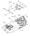
- the container 10 shown in FIG. 1 has a housing 12 and an insert 14.
- the housing 12 is box-shaped and open at a front side.
- the insert 14 is also box-shaped and open at an upper side.
- the insert 14 is slidably received in the housing 12 in the manner of a drawer.
- the housing 12 is provided for insertion into a designated mounting hole in a dashboard, not shown, of a motor vehicle, not shown.
- a scroll spring 16 which is mounted on a rear side of the insert 14 rotatable and unwound.
- a known per se, not visible in the drawing rotary damper is inserted into a side wall of the insert 14.
- a gear 20 of the rotary damper meshes with a non-visible rack of the housing 12.
- a locking mechanism 18,22 holds the insert 14 against the force of the scroll spring 16 in an inserted into the housing 12, the closed position.
- Such locking mechanisms 18, 22 are known per se as so-called.
- Push-push or heart cam locking mechanisms They are by pushing the insert 14 a short distance over the closed position away in the housing 12 in detachable.
- the container 10 has a safety locking mechanism according to the invention, which is arranged on an underside of a bottom 26 of the housing 12.
- the safety lock mechanism has a mass in the form of a weight 28 and a spring element 30 bent from a spring wire.
- the weight 28 and the Spring element 30 are shown in Figure 2 as individual parts, wherein Figure 2 shows the weight 28 and the spring element 30 from the other side as Figure 1.
- the weight 28 has a journal 32 at a side edge which is received in a bearing hole in the bottom 26 of the housing 12. In this way, the weight 28 is pivotally mounted about the bearing pin 32 on the bottom 26 of the housing 12. This pivotal mounting of the weight 28 forms a guide with which the weight 28 is guided in an arcuate path about the bearing pin 32 and with respect to the housing 12 in approximately forward and backward movable.
- the weight 28 On a side opposite the bearing journal 32, the weight 28 has a snap-action pin 34, which cooperates with the spring element 30: the spring element 30 has a curvature 36 in its center, in which the snap-action pin 34 rests.
- the spring element 30 forms with its curvature 36 and the snap pin 34 of the weight 28 a snap device 28, 30, 34, 38, which holds the weight 28 in a basic position. If the weight 28 acts on a force of sufficient magnitude directed forwards or backwards with respect to the housing 12, then the snap-action pin 34 is released from the curvature 36 and the weight 28 can pivot forwards or backwards.
- the spring element 30 In a position inserted into the housing 12, the spring element 30 is curved elastically arcuate, while it is in the relaxed state (Figure 2) is substantially straight.
- the spring element 30 has a trapezoidal or dovetail-shaped bend 38, in the middle of the curvature 36 is located. Pages of the trapezoidal or dovetailed bend 38 form undercuts where the snap pin 34 can snap. If the weight 28 swings forwards or backwards, its snap-in pin 34 reaches one of the two sides of the trapezoidal or dovetail-shaped bend 38 of the spring element 30 and is held snapped there. The weight 28 can not swing back so.
- the spring element 30 with its trapezoidal or dovetail-shaped bend 38 and the weight 28 with the snap-action pin 34 thus form a further snap-action device 28, 30, 34, 38, which holds the weight 28 snapped into the forward or backward tilted, ie deflected, position , A swinging back of the weight 28 in its normal position is not provided.
- the weight 28 to its normal position would have the spring element 30 are bent to the side, including the on the underside of the bottom 26 of the housing 12 arranged spring element 30 be accessible or, for example, would have to be made by removing the container 10 from the dashboard, not shown.
- the highest occurring in normal driving accelerations and decelerations are not sufficient to snap the snap pin 34 of the mass 28 from the curvature 36 of the spring element 30.
- the weight 28 has two arms 40 which extend in one piece from the weight 28 in extension of the side of the weight 28 on which the bearing pin 32 is provided.
- the arms 40 have cranks 42 at their free ends. If the weight 28 is deflected, i. pivoted to or from the rear, the crank 42 of an arm 40 engages through a recess 44 of the insert 14. The insert 14 is thereby locked in its inserted into the housing 12, the closed position.
- the function of the safety lock mechanism 24 is as follows: if a front or rear acceleration or deceleration is applied to the weight 28 by a front or rear impact of a motor vehicle in which the container 10 is installed, the snap pin 34 of the weight 28 snaps the curvature 36 of the spring element 30, the weight 28 is pivoted and locked with the crank 42 of his one arm 40, the insert 14 in the housing 12. At the same time, the snap pin 34 snaps on one side of the trapezoidal or dovetailed bend 38 of the spring element 30, so that the weight 28 pivots, ie remains deflected, even if the acceleration or deceleration subsides or acts in the opposite direction. The insert 14 thereby remains locked during and after an accident in the closed position in the housing 12.
- FIG. 3 shows one of the two deflected positions of the weight 28.
Description
Die Erfindung betrifft eine Sicherheitsverriegelungsmechanik für ein Behältnis in einem Fahrzeug mit den Merkmalen des Oberbegriffs des Anspruchs 1.The invention relates to a safety locking mechanism for a container in a vehicle with the features of the preamble of claim 1.
Die Sicherheitsverrieglungsmechanik ist insbesondere für einen Kraftwagen vorgesehen. Ein Behältnis kann bspw. ein Ablagefach mit einem schubladenartig ausfahrbaren Einschub sein. Ebenso lässt sich ein Deckel eines Ablage- oder Handschuhfachs oder an Stelle eines Behältnisses bspw. ein Schieber eines Getränkehalters mit der erfindungsgemäßen Sicherheitsverriegelungsmechanik im Falle eines Unfalls in einer geschlossenen Stellung verriegeln.The Sicherheitsverrieglungsmechanik is especially intended for a motor vehicle. A container can be, for example, a storage compartment with a drawer-like extendable slot. Likewise, a lid of a storage or glove compartment or instead of a container, for example, a slide of a beverage holder with the safety locking mechanism according to the invention in the event of an accident in a closed position lock.
Sicherheitsverriegelungsmechaniken sind an sich bekannt. Sie haben die Aufgabe, ein Öffnen eines Behältnisses, insbesondere ein Ausfahren eines Schiebers bei einem Unfall, insbesondere bei einem Front- und/oder Heckaufprall, zu verhindern. Es soll vermieden werden, dass Schieber, Deckel oder dgl. Teile in einen Fahrgastraum vorstehen und dadurch eine Verletzungsgefahr für Insassen bilden. Außerdem soll vermieden werden, dass durch Öffnen eines Behältnisses im Behältnis aufbewahrte Gegenstände in den Innenraum des Fahrzeuges gelangen, dort umherfliegen und eine Verletzungsgefahr bilden.Safety locking mechanisms are known per se. They have the task of preventing the opening of a container, in particular an extension of a slider in an accident, especially in a front and / or rear impact. It should be avoided that slide, cover or the like. Parts protrude into a passenger compartment, thereby forming a risk of injury to occupants. In addition, it is to be avoided that objects stored in the container by opening a container enter the interior of the vehicle, fly around there and form a risk of injury.
Eine derartige Sicherheitsverriegelungsmechanik, die dem Oberbegriff des Anspruchs 1 entspricht, ist in der EP 610 882 A2 offenbart. Die genannte Druckschrift offenbart ein Behältnis mit einem schubladenartig ausfahrbaren Einschub, der mit einem Federelement in eine offene Stellung ausgeschoben wird. Eine sog. Push-Push-Verriegelungsmechanik hält den Einschub gegen die Kraft des Federelements in einer eingeschobenen, geschlossenen Stellung. Die Verriegelungsmechanik weist ein hakenförmiges, federbeaufschlagtes Verriegelungselement auf. Zur Weiterbildung der Verriegelungsmechanik zu einer Sicherheitsverriegelungsmechanik sieht die genannte Druckschrift vor, das hakenförmige Verriegelungselement durch Formgebung weist ein hakenförmiges, federbeaufschlagtes Verriegelungselement auf. oder ein exzentrisch angeordnetes Gewicht so zu gestalten, dass eine bei einem Unfall auf das Verriegelungselement einwirkende Beschleunigung oder Verzögerung das Verriegelungselement entgegen einer Federkraft des Federelements beaufschlagt. Dadurch wird verhindert, dass das Verriegelungselement durch eine bei einem Unfall wirkende Beschleunigung oder Verzögerung außer Eingriff vom Einschub gelangt.Such a safety locking mechanism, which corresponds to the preamble of claim 1, is disclosed in EP 610 882 A2. The cited document discloses a container with a drawer-like retractable drawer, which is pushed out with a spring element in an open position. A so-called push-push locking mechanism holds the insert against the force of the spring element in an inserted, closed position. The locking mechanism has a hook-shaped, spring-loaded locking element. For further development of the locking mechanism to a safety locking mechanism, said document provides, the hook-shaped locking element by shaping has a hook-shaped, spring-loaded locking element. or to design an eccentrically arranged weight such that an acceleration or deceleration acting on the locking element in the event of an accident acts on the locking element counter to a spring force of the spring element. This prevents the locking element from coming out of engagement by accidental acceleration or deceleration.
Eine andere Sicherheitsverriegelungsmechanik offenbart die US-PS 5 052 728. Dort wird ein ebenfalls hakenförmiges Verriegelungselement durch eine verschiebbar geführte Masse an einem Schwenken und damit an einem außer Eingriff gelangen von einem schubladenartig ausfahrbaren Fach gehindert, wobei sich die Masse im Falle eines Unfalls gegen die Kraft eines Federelements bewegt.Another safety locking mechanism disclosed in US Patent No. 5,052,728. There is also a hook-shaped locking element prevented by a slidably guided mass on a pivoting and thus on a disengaged from a drawer-like extendable compartment, wherein the mass in the event of an accident against the Power of a spring element moves.
Der Erfindung liegt die Aufgabe zugrunde, eine Sicherheitsverriegelungsmechanik der vorstehend erläuterten Art vorzuschlagen, deren Sicherheit gegen ein Öffnen eines Behältnisses durch einen Unfall erhöht ist.The invention has for its object to propose a safety locking mechanism of the type described above, the safety is increased against opening a container by an accident.
Diese Aufgabe wird erfindungsgemäß durch die Merkmale des Anspruchs 1 gelöst. Die erfindungsgemäße Sicherheitsverriegelungsmechanik weist eine Masse auf, die mit einer Führung aus einer Grundstellung in eine ausgelenkte Stellung beweglich geführt ist. Die Führung kann eine gerade oder nicht gerade Schiebeführung sein. Ebenfalls ist eine Schwenklagerung möglich, die die Masse auf einer Kreisbogenbahn beweglich führt. Desweiteren weist die erfindungsgemäße Sicherheitsverriegelungsmechanik eine Einrichtung auf, die die Masse in einer Grundstellung hält, wenn keine Beschleunigung oder Verzögerung in Auslenkungsrichtung auf die Masse einwirkt. Diese Einrichtung kann bspw. ein Federelement aufweisen, das die Masse an einem Anschlag hält, wenn keine Beschleunigung/Verzögerung auf die Masse einwirkt. Eine Beschleunigung/Verzögerung kann die Masse gegen die Kraft des Federelements In einer Richtung bewegen, d.h. auslenken. Auch ist es möglich, die Masse mit einem Federelement in einer Grundstellung zu halten, in der das Federelement entspannt ist. Eine Auslenkung der Masse durch eine Beschleunigung/Verzögerung ist in zwei einander entgegengesetzten Richtungen, eventuell auch in einer oder mehreren Querrichtungen, möglich.This object is achieved by the features of claim 1. The safety locking mechanism according to the invention has a mass which is movably guided by a guide from a basic position into a deflected position. The guide can be a straight or not straight sliding guide. Also, a pivotal mounting is possible, which leads the mass on a circular arc path movable. Furthermore, the safety locking mechanism according to the invention has a device which holds the mass in a basic position when no acceleration or deceleration in the direction of deflection acts on the mass. This device may, for example, have a spring element which holds the mass against a stop when no acceleration / deceleration acts on the mass. An acceleration / deceleration can move the mass against the force of the spring element in one direction, ie deflect it. It is also possible to keep the mass with a spring element in a basic position in which the spring element is relaxed. A displacement of mass by an acceleration / deceleration is in two each other opposite directions, possibly in one or more transverse directions, possible.
Desweiteren sieht die Erfindung eine Schnappeinrichtung vor, die die Masse in der ausgelenkten Stellung hält, wenn die Masse durch eine auf sie einwirkende Beschleunigung oder Verzögerung in die ausgelenkte Stellung bewegt worden ist. In dieser Stellung hält die Masse das Behältnis verschlossen. Dabei kann die Masse das Behältnis unmittelbar oder auch mittelbar über bspw. ein Verriegelungselement geschlossen halten. Die Schnappeinrichtung hält das Behältnis auch verschlossen, wenn die Beschleunigung/Verzögerung nicht mehr wirkt. Das Behältnis ist dadurch nach einem Unfall nicht mehr öffenbar oder es muss jedenfalls vor einem Öffnen des Behältnisses die Schnappeinrichtung bspw. manuell gelöst werden. Dadurch vermeidet die Erfindung ein Öffnen des Behältnisses bspw. durch Erschütterungen während eines Unfalls oder auch durch eine Serie von Beschleunigungen und Verzögerungen bspw. bei einem Front- und anschließenden Heckaufprall. Die die Masse in der Grundstellung haltende Einrichtung ist so ausgebildet, dass die Masse nur durch eine Beschleunigung oder Verzögerung in die ausgelenkte Stellung bewegt werden kann, die einen vorgegebenen Wert überschreitet. Dieser Wert ist so hoch gewählt, dass beim gewöhnlichen Fahrbetrieb auftretende Beschleunigungen und Verzögerungen auch bei bspw. scharfem Bremsen oder starkem Beschleunigen die Masse nicht in die ausgelenkte Stellung bewegen. Die Masse gelangt also nur durch eine Beschleunigung oder Verzögerung, wie sie bei einem Unfall auftritt, in die ausgelenkte Stellung.Furthermore, the invention provides a snap device which holds the mass in the deflected position when the mass has been moved to the deflected position by an acceleration or deceleration acting on it. In this position, the mass holds the container closed. In this case, the mass can hold the container closed directly or indirectly via, for example, a locking element. The snap device keeps the container closed even if the acceleration / deceleration no longer works. The container is thus no longer openable after an accident or it must in any case before opening the container, the snap device, for example, be solved manually. Thus, the invention avoids opening the container, for example. By shaking during an accident or by a series of accelerations and delays, for example. In a front and then rear impact. The device holding the mass in the home position is designed so that the mass can be moved only by an acceleration or deceleration in the deflected position, which exceeds a predetermined value. This value is chosen so high that occurring during normal driving accelerations and decelerations even when, for example, sharp braking or strong acceleration, the mass does not move to the deflected position. The mass thus enters the deflected position only by an acceleration or deceleration, as occurs in an accident.
Eine Ausgestaltung der Erfindung sieht vor, dass die Masse in zwei entgegengesetzten Richtungen auslenkbar ist, in jeder der beiden ausgelenkten Stellungen von einer Schnappeinrichtung gehalten wird und in jeder ausgelenkten Stellung das Behältnis verschlossen hält. Die beiden Richtungen sind vorzugsweise so gewählt, dass eine Beschleunigung oder Verzögerung in Längsrichtung des Fahrzeugs die Masse auslenkt. Die Sicherheitsverriegelungsmechanik ist dadurch bei einem Front- oder Heckaufprall wirksam. Soll die Sicherheitsverriegelungsmechanik auch für einen Seitenaufprall wirksam sein, kann eine Längs- und Querführung oder eine Führung der Masse mit Freiheitsgraden in Längs- und Querrichtung oder es kann eine zweite Sicherheitsverriegelungsmechanik für die Querrichtung vorgesehen werden. Die Masse kann in jeder ausgelenkten Stellung von einer Schnappeinrichtung gehalten werden oder es wird eine Schnappeinrichtung vorgesehen, die die Masse in jeder ausgelenkten Stellung hält.An embodiment of the invention provides that the mass is deflectable in two opposite directions, is held in each of the two deflected positions of a snap device and keeps the container closed in each deflected position. The two directions are preferably selected such that an acceleration or deceleration in the longitudinal direction of the vehicle deflects the mass. The safety locking mechanism is thereby effective in a front or rear impact. If the safety locking mechanism is also to be effective for a side impact, a longitudinal and transverse guide or a guide of the mass with degrees of freedom in the longitudinal and transverse direction or a second safety locking mechanism for the transverse direction can be provided. The mass can be in each deflected position are held by a snap device or a snap device is provided which holds the mass in each deflected position.
Die die Masse in der Grundstellung haltende Einrichtung kann bspw. ein Federelement sein, gegen dessen Kraft die Masse auslenkbar ist. Erst wenn die Auslenkung einen vorgegebenen Weg und damit eine vorgegebenen Kraft überschreitet wird die Schnappeinrichtung wirksam, die die Masse in der ausgelenkten Stellung hält. Dadurch ist sichergestellt, dass nur eine Beschleunigung oder Verzögerung, wie sie bei einem Unfall auftritt und nicht eine Beschleunigung oder Verzögerung, wie sie beim normalen Fahrbetrieb auftritt, die Masse in der ausgelenkten Stellung an der Schnappeinrichtung einschnappen kann.The device holding the mass in the basic position can, for example, be a spring element against whose force the mass can be deflected. Only when the deflection exceeds a predetermined path and thus a predetermined force is the snap device effective, which holds the mass in the deflected position. This ensures that only an acceleration or deceleration, as occurs in an accident and not an acceleration or deceleration, as occurs in normal driving, the mass can snap in the deflected position on the snap device.
Eine Ausgestaltung der Erfindung sieht vor, die die Masse in der Grundstellung haltende Einrichtung ebenfalls als eine Art Schnappeinrichtung auszubilden, von der die Masse nur frei kommt, wenn die auf sie einwirkende Beschleunigung oder Verzögerung einen Schwellenwert überschreitet. Auch dies stellt sicher, dass die erfindungsgemäße Sicherheitsverriegelungsmechanik nur bei einem Unfall und nicht beim normalen Fahrbetrieb wirksam wird. Durch eine Schnappeinrichtung oder dgl. lässt sich der Schwellenwert der zum Auslenken der Masse notwendigen Beschleunigung oder Verzögerung exakter vorgeben und dadurch eine Fehlfunktion mit größerer Zuverlässigkeit vermeiden. Fehlfunktion können sowohl ein Geschlossenhalten des Behältnisses durch im gewöhnlichen Fahrbetrieb auftretende Beschleunigungen und Verzögerungen als auch ein Nichtgeschlossenhalten des Behältnisses bei einem Unfall sein.An embodiment of the invention provides that also form the mass in the home position holding device as a kind of snap device from which the mass only comes free when the acceleration or deceleration acting on them exceeds a threshold. This also ensures that the safety locking mechanism according to the invention is effective only in an accident and not during normal driving. By means of a snap-action device or the like, the threshold value of the acceleration or deceleration necessary for deflecting the mass can be predetermined more precisely, thereby avoiding a malfunction with greater reliability. Malfunctioning can be both keeping the container closed by accelerations and decelerations occurring in normal driving operation and non-closing of the container in the event of an accident.
Eine Ausgestaltung der Erfindung sieht ein Federelement vor, das sowohl die die Masse in der Grundstellung haltende Einrichtung als auch die die Masse in der ausgelenkten Stellung haltende Schnappeinrichtung bildet. Diese Ausgestaltung der Erfindung ermöglicht eine einfache und preisgünstige Ausbildungsmöglichkeit der Sicherheitsverriegelungsmechanik. Als Federelemente kommen außer Metall- auch Kunststoff- oder sonstige Federelemente in Betracht.An embodiment of the invention provides a spring element which forms both the device holding the mass in the basic position and the snap-in device holding the mass in the deflected position. This embodiment of the invention enables a simple and inexpensive training option of safety locking mechanism. As spring elements come in addition to metal and plastic or other spring elements into consideration.
Die Erfindung wird nachfolgend anhand eines in der Zeichnung dargestellten Ausführungsbeispiels näher erläutert. Es zeigen:
- Figur 1
- ein öffenbares Behältnis mit einer Ausführungsform einer erfindungsgemäßen Sicherheitsverriegelungsmechanik in perspektivischer Explosionsdarstellung teilweise aufgebrochen;
- Figur 2
- Einzelteile der Sicherheitsverriegelungsmechanik des Behältnisses aus Figur 1; und
- Figur 3
- ein Gehäuse des Behältnisses aus Figur 1 in derselben Perspektive mit einer Masse in ausgelenkter Stellung.
- FIG. 1
- an openable container with an embodiment of a safety locking mechanism according to the invention in a perspective exploded view partially broken;
- FIG. 2
- Individual parts of the safety locking mechanism of the container of Figure 1; and
- FIG. 3
- a housing of the container of Figure 1 in the same perspective with a mass in the deflected position.
Das in Figur 1 dargestellte Behältnis 10 weist ein Gehäuse 12 und einen Einschub 14 auf. Das Gehäuse 12 ist schachtelförmig und an einer Vorderseite offen. Der Einschub 14 ist ebenfalls schachtelförmig und an einer Oberseite offen. Der Einschub 14 ist nach Art einer Schublade verschieblich im Gehäuse 12 aufgenommen. Das Gehäuse 12 ist zum Einsetzen in eine dafür vorgesehene Einbauöffnung in einem nicht dargestellten Armaturenbrett eines nicht dargestellten Kraftwagens vorgesehen.The
Zum Ausschieben des Einschubs 14 in eine aus einer Vorderseite des Gehäuses 12 vorstehende, geöffnete Stellung weist das Behältnis 12 eine Rollfeder 16 auf, die an einer Rückseite des Einschubs 14 dreh- und abwickelbar angebracht ist. Zur Dämpfung der Ausfahrbewegung ist ein an sich bekannter, in der Zeichnung nicht sichtbarer Rotationsdämpfer in eine Seitenwand des Einschubs 14 eingesetzt. Ein Zahnrad 20 des Rotationsdämpfers kämmt mit einer nicht sichtbaren Zahnstange des Gehäuses 12. Eine Verriegelungsmechanik 18,22 hält den Einschub 14 gegen die Kraft der Rollfeder 16 in einer in das Gehäuse 12 eingeschobenen, geschlossenen Stellung. Derartige Verriegelungsmechaniken 18, 22 sind als sog. Push-Push- oder Herzkurven-Verriegelungsmechaniken an sich bekannt. Sie sind durch Eindrücken des Einschubs 14 ein kurzes Stück über die geschlossene Stellung hinweg in das Gehäuse 12 hinein lösbar.For pushing out the
Das Behältnis 10 weist eine erfindungsgemäße Sicherheitsverriegelungsmechanik auf, die an einer Unterseite eines Bodens 26 des Gehäuses 12 angeordnet ist. Die Sicherheitsverriegelungsmechanik weist eine Masse in Form eines Gewichts 28 und ein Federelement 30, das aus einem Federdraht gebogen ist, auf. Das Gewicht 28 und das Federelement 30 sind in Figur 2 als Einzelteile dargestellt, wobei Figur 2 das Gewicht 28 und das Federelement 30 von der anderen Seite wie Figur 1 zeigt. Das Gewicht 28 weist einen Lagerzapfen 32 an einem Seitenrand auf, der in einem Lagerloch im Boden 26 des Gehäuses 12 aufgenommen ist. Auf diese Weise ist das Gewicht 28 um den Lagerzapfen 32 schwenkbar am Boden 26 des Gehäuses 12 gelagert. Diese Schwenklagerung des Gewichts 28 bildet eine Führung, mit der das Gewicht 28 auf einer Kreisbogenbahn um den Lagerzapfen 32 und in Bezug auf das Gehäuse 12 in etwa nach vorn und nach hinten bewegbar geführt ist.The
Auf einer dem Lagerzapfen 32 gegenüberliegenden Seite weist das Gewicht 28 einen Schnappzapfen 34 auf, der mit dem Federelement 30 zusammenwirkt: das Federelement 30 weist in seiner Mitte eine Wölbung 36 auf, in der der Schnappzapfen 34 einliegt. Das Federelement 30 bildet mit seiner Wölbung 36 und dem Schnappzapfen 34 des Gewichts 28 eine Schnappeinrichtung 28, 30, 34, 38, die das Gewicht 28 in einer Grundstellung hält. Greift am Gewicht 28 eine in Bezug auf das Gehäuse 12 nach vorn oder nach hinten gerichtete Kraft ausreichender Größe an, so kommt der Schnappzapfen 34 aus der Wölbung 36 frei und das Gewicht 28 kann nach vorn oder nach hinten schwenken. In einer in das Gehäuse 12 eingesetzten Stellung ist das Federelement 30 elastisch bogenförmig gewölbt, wogegen es in entspanntem Zustand (Figur 2) im wesentlichen gerade ist.On a side opposite the
Ebenfalls in seiner Mitte weist das Federelement 30 eine trapez- oder schwalbenschwanzförmige Biegung 38 auf, in deren Mitte sich die Wölbung 36 befindet. Seiten der trapez- oder schwalbenschwanzförmigen Biegung 38 bilden Hinterschneidungen, an denen der Schnappzapfen 34 einschnappen kann. Schwenkt das Gewicht 28 nach vorn oder hinten, so gelangt sein Schnappzapfen 34 auf eine der beiden Seiten der trapez- oder schwalbenschwanzförmigen Biegung 38 des Federelements 30 und wird dort eingeschnappt gehalten. Das Gewicht 28 kann also nicht mehr zurückschwenken. Das Federelement 30 mit seiner trapez- oder schwalbenschwanzförmigen Biegung 38 und das Gewicht 28 mit dem Schnappzapfen 34 bilden also eine weitere Schnappeinrichtung 28, 30, 34,38, die das Gewicht 28 in der nach vorn oder nach hinten geschwenkten, d.h. ausgelenkten Stellung eingeschnappt hält. Ein Zurückschwenken des Gewichts 28 in seine Grundstellung ist nicht vorgesehen. Um das Gewicht 28 in seine Grundstellung zurückzuschwenken müsste das Federelement 30 zur Seite gebogen werden, wozu das an der Unterseite des Bodens 26 des Gehäuses 12 angeordnete Federelement 30 zugänglich sein oder bspw. durch Ausbau des Behältnisses 10 aus dem nicht dargestellten Armaturenbrett gemacht werden müsste. Die höchsten im normalen Fahrbetrieb auftretenden Beschleunigungen und Verzögerungen reichen nicht aus, um den Schnappzapfen 34 der Masse 28 aus der Wölbung 36 des Federelements 30 auszuschnappen.Also in its center, the
Das Gewicht 28 weist zwei Arme 40 auf, die in Verlängerung der Seite des Gewichts 28, an der der Lagerzapfen 32 vorgesehen ist, einstückig vom Gewicht 28 abstehen. Die Arme 40 weisen Kröpfungen 42 an ihren freien Enden auf. Ist das Gewicht 28 ausgelenkt, d.h. nach vom oder hinten verschwenkt, durchgreift die Kröpfung 42 eines Arms 40 eine Aussparung 44 des Einschubs 14 ein. Der Einschub 14 ist dadurch in seiner in das Gehäuse 12 eingeschobenen, geschlossenen Stellung verriegelt.The
Die Funktion der erfindungsgemäßen Sicherheitsverriegelungsmechanik 24 ist folgende: wird durch einen Front- oder Heckaufprall eines Kraftwagens, in den das Behältnis 10 eingebaut ist, eine nach vorn oder hinten gerichtete Beschleunigung oder Verzögerung auf das Gewicht 28 ausgeübt, schnappt der Schnappzapfen 34 des Gewichts 28 aus der Wölbung 36 des Federelements 30 aus, das Gewicht 28 verschwenkt und verriegelt mit der Kröpfung 42 seines einen Arms 40 den Einschub 14 im Gehäuse 12. Zugleich schnappt der Schnappzapfen 34 an einer Seite der trapez- oder schwalbenschwanzförmigen Biegung 38 des Federelements 30 ein, so dass das Gewicht 28 verschwenkt, d.h. ausgelenkt bleibt, auch wenn die Beschleunigung oder Verzögerung abklingt oder in entgegengesetzter Richtung wirkt. Der Einschub 14 bleibt dadurch während und nach einem Unfall in der geschlossenen Stellung im Gehäuse 12 verriegelt. In Figur 3 ist eine der beiden ausgelenkten Stellungen des Gewichts 28 dargestellt.The function of the safety lock mechanism 24 according to the invention is as follows: if a front or rear acceleration or deceleration is applied to the
Claims (4)
- Safety locking mechanism for a receptacle in a vehicle, having a mass which is guided by a guide means so that it can move from a home position into a deflected position, in the used state the mass holding the receptacle closed when the mass has been moved into the deflected position, and having a device which holds the mass in the home position when no acceleration or deceleration acts on the mass in the deflection direction, characterised in that the safety locking mechanism (24) has a snap-in device (28, 30, 34, 38) which holds the mass (28) in the deflected position.
- Safety locking mechanism according to claim 1, characterised in that the mass (28) is arranged to be deflected in two opposite directions, is held in each deflected position by a snap-in device (28, 30, 34, 38) and in each deflected position holds the receptacle (10) closed.
- Safety locking mechanism according to claim 1, characterised in that the device (28, 30, 34, 38) holding the mass (28) in the home position holds the mass (28) in the home position for as long as acceleration or deceleration acting on the mass (28) in the deflection direction does not exceed a threshold value.
- Safety locking mechanism according to claim 1, characterised in that the safety locking mechanism (24) has a spring element (30) which forms the device (28, 30, 34, 38) holding the mass (28) in the home position and the snap-in device (28, 30, 34, 38) holding the mass (28) in the deflected position.
Applications Claiming Priority (3)
| Application Number | Priority Date | Filing Date | Title |
|---|---|---|---|
| DE10224862 | 2002-06-05 | ||
| DE2002124862 DE10224862A1 (en) | 2002-06-05 | 2002-06-05 | Safety locking device for a container in a vehicle |
| PCT/EP2003/005656 WO2003104591A1 (en) | 2002-06-05 | 2003-05-30 | Safety locking device for a container in a vehicle |
Publications (2)
| Publication Number | Publication Date |
|---|---|
| EP1509663A1 EP1509663A1 (en) | 2005-03-02 |
| EP1509663B1 true EP1509663B1 (en) | 2007-01-10 |
Family
ID=29594272
Family Applications (1)
| Application Number | Title | Priority Date | Filing Date |
|---|---|---|---|
| EP03735497A Expired - Lifetime EP1509663B1 (en) | 2002-06-05 | 2003-05-30 | Safety locking device for a container in a vehicle |
Country Status (4)
| Country | Link |
|---|---|
| US (1) | US7156427B2 (en) |
| EP (1) | EP1509663B1 (en) |
| DE (2) | DE10224862A1 (en) |
| WO (1) | WO2003104591A1 (en) |
Cited By (1)
| Publication number | Priority date | Publication date | Assignee | Title |
|---|---|---|---|---|
| DE102010060953A1 (en) | 2010-12-02 | 2012-06-06 | Fischer Automotive Systems Gmbh & Co. Kg | Safety locking device for a container in a vehicle |
Families Citing this family (8)
| Publication number | Priority date | Publication date | Assignee | Title |
|---|---|---|---|---|
| DE10340673A1 (en) * | 2003-09-04 | 2005-03-31 | Fischer Automotive Systems Gmbh | Safety locking device for a container in a vehicle |
| ITRM20040337A1 (en) * | 2004-07-07 | 2004-10-07 | Valeo Sicurezza Abitacolo Spa | DOOR HANDLE, IN PARTICULAR OF THE VEHICLE, WITH INERTIAL SAFETY SYSTEM. |
| US7793995B2 (en) * | 2006-07-27 | 2010-09-14 | Illinois Tool Works Inc. | Push/push latch |
| DE102006049333A1 (en) * | 2006-10-19 | 2008-04-30 | Fischer Automotive Systems Gmbh | Accidental locking device for e.g. glove box, in e.g. automobile, has vibratory host-spring-systems bringing latch from deflected position into locking position, where host-spring-systems have different frequencies, and rotating oscillator |
| WO2009005786A1 (en) * | 2007-06-29 | 2009-01-08 | Bbi Enterprises Group, Inc. | Trim assembly for a vehicle |
| FR2958218B1 (en) * | 2010-03-31 | 2012-05-04 | Faurecia Interieur Ind | DEVICE FOR EQUIPPING THE INTERIOR OF A MOTOR VEHICLE WITH A PUSH-PUSH TYPE CONTROL MECHANISM |
| DE202010006291U1 (en) * | 2010-04-30 | 2011-09-23 | Minda Ktsn Plastic Solutions Gmbh & Co.Kg | locking device |
| JP2019018415A (en) * | 2017-07-13 | 2019-02-07 | キヤノン株式会社 | Recording device and method for controlling the recording |
Family Cites Families (11)
| Publication number | Priority date | Publication date | Assignee | Title |
|---|---|---|---|---|
| JPS606650U (en) * | 1983-06-22 | 1985-01-18 | 本田技研工業株式会社 | Small item storage box installed on the vehicle instrument panel |
| US4973014A (en) * | 1988-06-27 | 1990-11-27 | Creative Systems Engineering, Inc. | Conduit bracket lock system |
| JPH077225Y2 (en) * | 1989-10-18 | 1995-02-22 | 株式会社ニフコ | Closed position locking device for vehicle-mounted vehicle |
| US5312143A (en) * | 1992-11-19 | 1994-05-17 | Buckner Almar W | Earthquake safety cabinet latch |
| DE69400926T2 (en) * | 1993-02-12 | 1997-06-12 | Kato Hatsujo Kaisha Ltd | Preservation device with a safety function |
| US5292159A (en) * | 1993-03-24 | 1994-03-08 | Nyx, Inc. | Latch mechanism for vehicle glove boxes or the like |
| DE9412661U1 (en) * | 1994-08-05 | 1994-10-06 | Sidler Gmbh & Co | Locking device |
| US5597188A (en) * | 1995-06-19 | 1997-01-28 | Miche; John A. | Earthquake latch |
| DE10120435A1 (en) | 2001-04-26 | 2002-10-31 | Fischer Artur Werke Gmbh | Push-push locking mechanism |
| DE10121681A1 (en) * | 2001-05-04 | 2002-11-07 | Volkswagen Ag | Locking device for housing in motor vehicle has component movably mounted in holder so that section of guide component can leave central section of guide for relocation of closing device from closed to open position |
| DE50214071D1 (en) * | 2002-09-06 | 2010-01-21 | Hawa Ag | Device for locking a separating element |
-
2002
- 2002-06-05 DE DE2002124862 patent/DE10224862A1/en not_active Withdrawn
-
2003
- 2003-05-30 DE DE50306261T patent/DE50306261D1/en not_active Expired - Lifetime
- 2003-05-30 US US10/516,048 patent/US7156427B2/en not_active Expired - Lifetime
- 2003-05-30 EP EP03735497A patent/EP1509663B1/en not_active Expired - Lifetime
- 2003-05-30 WO PCT/EP2003/005656 patent/WO2003104591A1/en active IP Right Grant
Cited By (2)
| Publication number | Priority date | Publication date | Assignee | Title |
|---|---|---|---|---|
| DE102010060953A1 (en) | 2010-12-02 | 2012-06-06 | Fischer Automotive Systems Gmbh & Co. Kg | Safety locking device for a container in a vehicle |
| WO2012072206A1 (en) | 2010-12-02 | 2012-06-07 | Fischer Automotive Systems Gmbh & Co. Kg | Safety locking device for a container in a vehicle |
Also Published As
| Publication number | Publication date |
|---|---|
| US20050173931A1 (en) | 2005-08-11 |
| WO2003104591A1 (en) | 2003-12-18 |
| DE10224862A1 (en) | 2003-12-24 |
| US7156427B2 (en) | 2007-01-02 |
| EP1509663A1 (en) | 2005-03-02 |
| DE50306261D1 (en) | 2007-02-22 |
Similar Documents
| Publication | Publication Date | Title |
|---|---|---|
| DE102005043593B4 (en) | Storage compartment for a motor vehicle | |
| DE19835364C2 (en) | Device for installation in a motor vehicle with a pull-out part | |
| EP2171189B1 (en) | Locking device for the bonnet of a motor vehicle | |
| EP3105082B1 (en) | Camera device | |
| EP1509663B1 (en) | Safety locking device for a container in a vehicle | |
| DE102006014822B4 (en) | Interior fitting for vehicles | |
| DE102010050800A1 (en) | Locking device for e.g. ashtray of motor car, has inertia-controlled locking bolt transferred under influence of external acceleration forces in pivot direction of box or cover in position in which movement of curve latch is blocked | |
| DE102004003165A1 (en) | Locking mechanism and device for opening and closing | |
| DE102005027379B4 (en) | Locking device for a cover on a storage compartment in a motor vehicle | |
| DE102011053395A1 (en) | Central console assembly for use in motor vehicle, has open-top storage compartment closed by pivotally mounted lid at rear end of storage compartment, and crash-lock device for preventing unintentional opening of lid in event of crash | |
| EP1660743B1 (en) | Safety locking device for a container in a vehicle | |
| DE10027020A1 (en) | Central console for vehicles has swivel lid above removable drawer which moves in and out through wall opening in rear cross wall and closes opening when fully pushed in | |
| EP2534326B1 (en) | Retracting device for sliding doors | |
| DE10009291B4 (en) | Armrest with storage compartment and lockable lid | |
| WO2013098323A1 (en) | Safety locking device, storage compartment with safety locking device and method for acceleration-activated locking of a storage compartment release | |
| DE102008000098A1 (en) | Outside door handle assembly for vehicles | |
| EP2072717A1 (en) | Paddle-type handle unit, in particular for a depositing/storage compartment of a motor vehicle | |
| DE102010023731A1 (en) | Locking device for vehicle door in motor car, has pivotable component comprising mass body that is operatively connected with locking unit for deflection of mass body, where locking unit blocks movement of pivotable component | |
| EP1582403B1 (en) | Holding device for a food or beverage container | |
| DE10022436A1 (en) | Damping system for a component displaceable from an initial position to an end position comprises an additional braking element which comes into action directly before the end of the displacement process | |
| EP3990727B1 (en) | Locking device for a container or lid, in particular of motor vehicles, which can be actuated between a closed and open position | |
| DE19911589C5 (en) | Vehicle seat, in particular motor vehicle seat, with an actuating device | |
| DE102004063119B4 (en) | safety lock | |
| DE102017123410B4 (en) | AXIAL CRASH LOCKING DEVICE | |
| DE10101818B4 (en) | Device for locking a push body |
Legal Events
| Date | Code | Title | Description |
|---|---|---|---|
| PUAI | Public reference made under article 153(3) epc to a published international application that has entered the european phase |
Free format text: ORIGINAL CODE: 0009012 |
|
| 17P | Request for examination filed |
Effective date: 20041112 |
|
| AK | Designated contracting states |
Kind code of ref document: A1 Designated state(s): AT BE BG CH CY CZ DE DK EE ES FI FR GB GR HU IE IT LI LU MC NL PT RO SE SI SK TR |
|
| GRAP | Despatch of communication of intention to grant a patent |
Free format text: ORIGINAL CODE: EPIDOSNIGR1 |
|
| GRAS | Grant fee paid |
Free format text: ORIGINAL CODE: EPIDOSNIGR3 |
|
| GRAA | (expected) grant |
Free format text: ORIGINAL CODE: 0009210 |
|
| AK | Designated contracting states |
Kind code of ref document: B1 Designated state(s): AT BE BG CH CY CZ DE DK EE ES FI FR GB GR HU IE IT LI LU MC NL PT RO SE SI SK TR |
|
| PG25 | Lapsed in a contracting state [announced via postgrant information from national office to epo] |
Ref country code: SI Free format text: LAPSE BECAUSE OF FAILURE TO SUBMIT A TRANSLATION OF THE DESCRIPTION OR TO PAY THE FEE WITHIN THE PRESCRIBED TIME-LIMIT Effective date: 20070110 Ref country code: FI Free format text: LAPSE BECAUSE OF FAILURE TO SUBMIT A TRANSLATION OF THE DESCRIPTION OR TO PAY THE FEE WITHIN THE PRESCRIBED TIME-LIMIT Effective date: 20070110 Ref country code: NL Free format text: LAPSE BECAUSE OF FAILURE TO SUBMIT A TRANSLATION OF THE DESCRIPTION OR TO PAY THE FEE WITHIN THE PRESCRIBED TIME-LIMIT Effective date: 20070110 Ref country code: IE Free format text: LAPSE BECAUSE OF FAILURE TO SUBMIT A TRANSLATION OF THE DESCRIPTION OR TO PAY THE FEE WITHIN THE PRESCRIBED TIME-LIMIT Effective date: 20070110 Ref country code: DK Free format text: LAPSE BECAUSE OF FAILURE TO SUBMIT A TRANSLATION OF THE DESCRIPTION OR TO PAY THE FEE WITHIN THE PRESCRIBED TIME-LIMIT Effective date: 20070110 |
|
| REG | Reference to a national code |
Ref country code: GB Ref legal event code: FG4D Free format text: NOT ENGLISH |
|
| REG | Reference to a national code |
Ref country code: IE Ref legal event code: FG4D Free format text: LANGUAGE OF EP DOCUMENT: GERMAN |
|
| REF | Corresponds to: |
Ref document number: 50306261 Country of ref document: DE Date of ref document: 20070222 Kind code of ref document: P |
|
| PG25 | Lapsed in a contracting state [announced via postgrant information from national office to epo] |
Ref country code: SE Free format text: LAPSE BECAUSE OF FAILURE TO SUBMIT A TRANSLATION OF THE DESCRIPTION OR TO PAY THE FEE WITHIN THE PRESCRIBED TIME-LIMIT Effective date: 20070410 |
|
| PG25 | Lapsed in a contracting state [announced via postgrant information from national office to epo] |
Ref country code: BG Free format text: LAPSE BECAUSE OF EXPIRATION OF PROTECTION Effective date: 20070411 |
|
| PG25 | Lapsed in a contracting state [announced via postgrant information from national office to epo] |
Ref country code: ES Free format text: LAPSE BECAUSE OF FAILURE TO SUBMIT A TRANSLATION OF THE DESCRIPTION OR TO PAY THE FEE WITHIN THE PRESCRIBED TIME-LIMIT Effective date: 20070421 |
|
| GBT | Gb: translation of ep patent filed (gb section 77(6)(a)/1977) |
Effective date: 20070412 |
|
| PG25 | Lapsed in a contracting state [announced via postgrant information from national office to epo] |
Ref country code: PT Free format text: LAPSE BECAUSE OF FAILURE TO SUBMIT A TRANSLATION OF THE DESCRIPTION OR TO PAY THE FEE WITHIN THE PRESCRIBED TIME-LIMIT Effective date: 20070611 |
|
| ET | Fr: translation filed | ||
| NLV1 | Nl: lapsed or annulled due to failure to fulfill the requirements of art. 29p and 29m of the patents act | ||
| REG | Reference to a national code |
Ref country code: IE Ref legal event code: FD4D |
|
| PLBE | No opposition filed within time limit |
Free format text: ORIGINAL CODE: 0009261 |
|
| STAA | Information on the status of an ep patent application or granted ep patent |
Free format text: STATUS: NO OPPOSITION FILED WITHIN TIME LIMIT |
|
| PG25 | Lapsed in a contracting state [announced via postgrant information from national office to epo] |
Ref country code: SK Free format text: LAPSE BECAUSE OF FAILURE TO SUBMIT A TRANSLATION OF THE DESCRIPTION OR TO PAY THE FEE WITHIN THE PRESCRIBED TIME-LIMIT Effective date: 20070110 |
|
| 26N | No opposition filed |
Effective date: 20071011 |
|
| BERE | Be: lapsed |
Owner name: FISCHER AUTOMOTIVE SYSTEMS G.M.B.H. Effective date: 20070531 |
|
| PG25 | Lapsed in a contracting state [announced via postgrant information from national office to epo] |
Ref country code: RO Free format text: LAPSE BECAUSE OF FAILURE TO SUBMIT A TRANSLATION OF THE DESCRIPTION OR TO PAY THE FEE WITHIN THE PRESCRIBED TIME-LIMIT Effective date: 20070110 |
|
| REG | Reference to a national code |
Ref country code: CH Ref legal event code: PL |
|
| PG25 | Lapsed in a contracting state [announced via postgrant information from national office to epo] |
Ref country code: MC Free format text: LAPSE BECAUSE OF NON-PAYMENT OF DUE FEES Effective date: 20070531 |
|
| PG25 | Lapsed in a contracting state [announced via postgrant information from national office to epo] |
Ref country code: CH Free format text: LAPSE BECAUSE OF NON-PAYMENT OF DUE FEES Effective date: 20070531 Ref country code: LI Free format text: LAPSE BECAUSE OF NON-PAYMENT OF DUE FEES Effective date: 20070531 |
|
| PG25 | Lapsed in a contracting state [announced via postgrant information from national office to epo] |
Ref country code: BE Free format text: LAPSE BECAUSE OF NON-PAYMENT OF DUE FEES Effective date: 20070531 |
|
| PG25 | Lapsed in a contracting state [announced via postgrant information from national office to epo] |
Ref country code: GR Free format text: LAPSE BECAUSE OF FAILURE TO SUBMIT A TRANSLATION OF THE DESCRIPTION OR TO PAY THE FEE WITHIN THE PRESCRIBED TIME-LIMIT Effective date: 20070411 |
|
| PGFP | Annual fee paid to national office [announced via postgrant information from national office to epo] |
Ref country code: CZ Payment date: 20080526 Year of fee payment: 6 |
|
| PG25 | Lapsed in a contracting state [announced via postgrant information from national office to epo] |
Ref country code: AT Free format text: LAPSE BECAUSE OF NON-PAYMENT OF DUE FEES Effective date: 20070530 |
|
| PGFP | Annual fee paid to national office [announced via postgrant information from national office to epo] |
Ref country code: IT Payment date: 20080522 Year of fee payment: 6 |
|
| PG25 | Lapsed in a contracting state [announced via postgrant information from national office to epo] |
Ref country code: EE Free format text: LAPSE BECAUSE OF FAILURE TO SUBMIT A TRANSLATION OF THE DESCRIPTION OR TO PAY THE FEE WITHIN THE PRESCRIBED TIME-LIMIT Effective date: 20070110 |
|
| PG25 | Lapsed in a contracting state [announced via postgrant information from national office to epo] |
Ref country code: CY Free format text: LAPSE BECAUSE OF FAILURE TO SUBMIT A TRANSLATION OF THE DESCRIPTION OR TO PAY THE FEE WITHIN THE PRESCRIBED TIME-LIMIT Effective date: 20070110 |
|
| PG25 | Lapsed in a contracting state [announced via postgrant information from national office to epo] |
Ref country code: LU Free format text: LAPSE BECAUSE OF NON-PAYMENT OF DUE FEES Effective date: 20070530 |
|
| PG25 | Lapsed in a contracting state [announced via postgrant information from national office to epo] |
Ref country code: HU Free format text: LAPSE BECAUSE OF FAILURE TO SUBMIT A TRANSLATION OF THE DESCRIPTION OR TO PAY THE FEE WITHIN THE PRESCRIBED TIME-LIMIT Effective date: 20070711 Ref country code: TR Free format text: LAPSE BECAUSE OF FAILURE TO SUBMIT A TRANSLATION OF THE DESCRIPTION OR TO PAY THE FEE WITHIN THE PRESCRIBED TIME-LIMIT Effective date: 20070110 |
|
| PG25 | Lapsed in a contracting state [announced via postgrant information from national office to epo] |
Ref country code: CZ Free format text: LAPSE BECAUSE OF NON-PAYMENT OF DUE FEES Effective date: 20090530 |
|
| REG | Reference to a national code |
Ref country code: FR Ref legal event code: ST Effective date: 20100129 |
|
| PG25 | Lapsed in a contracting state [announced via postgrant information from national office to epo] |
Ref country code: FR Free format text: LAPSE BECAUSE OF NON-PAYMENT OF DUE FEES Effective date: 20090602 |
|
| PGFP | Annual fee paid to national office [announced via postgrant information from national office to epo] |
Ref country code: FR Payment date: 20080526 Year of fee payment: 6 |
|
| PG25 | Lapsed in a contracting state [announced via postgrant information from national office to epo] |
Ref country code: IT Free format text: LAPSE BECAUSE OF NON-PAYMENT OF DUE FEES Effective date: 20090530 |
|
| PGFP | Annual fee paid to national office [announced via postgrant information from national office to epo] |
Ref country code: GB Payment date: 20110520 Year of fee payment: 9 |
|
| GBPC | Gb: european patent ceased through non-payment of renewal fee |
Effective date: 20120530 |
|
| PG25 | Lapsed in a contracting state [announced via postgrant information from national office to epo] |
Ref country code: GB Free format text: LAPSE BECAUSE OF NON-PAYMENT OF DUE FEES Effective date: 20120530 |
|
| PGFP | Annual fee paid to national office [announced via postgrant information from national office to epo] |
Ref country code: DE Payment date: 20210423 Year of fee payment: 19 |
|
| REG | Reference to a national code |
Ref country code: DE Ref legal event code: R119 Ref document number: 50306261 Country of ref document: DE |
|
| PG25 | Lapsed in a contracting state [announced via postgrant information from national office to epo] |
Ref country code: DE Free format text: LAPSE BECAUSE OF NON-PAYMENT OF DUE FEES Effective date: 20221201 |