EP1508696A1 - Dichtungsanordnung für ein Zylinder-Kolben-System - Google Patents
Dichtungsanordnung für ein Zylinder-Kolben-System Download PDFInfo
- Publication number
- EP1508696A1 EP1508696A1 EP04016803A EP04016803A EP1508696A1 EP 1508696 A1 EP1508696 A1 EP 1508696A1 EP 04016803 A EP04016803 A EP 04016803A EP 04016803 A EP04016803 A EP 04016803A EP 1508696 A1 EP1508696 A1 EP 1508696A1
- Authority
- EP
- European Patent Office
- Prior art keywords
- sealing
- piston
- arrangement according
- sealing arrangement
- shaped
- Prior art date
- Legal status (The legal status is an assumption and is not a legal conclusion. Google has not performed a legal analysis and makes no representation as to the accuracy of the status listed.)
- Granted
Links
Images



Classifications
-
- F—MECHANICAL ENGINEERING; LIGHTING; HEATING; WEAPONS; BLASTING
- F04—POSITIVE - DISPLACEMENT MACHINES FOR LIQUIDS; PUMPS FOR LIQUIDS OR ELASTIC FLUIDS
- F04B—POSITIVE-DISPLACEMENT MACHINES FOR LIQUIDS; PUMPS
- F04B53/00—Component parts, details or accessories not provided for in, or of interest apart from, groups F04B1/00 - F04B23/00 or F04B39/00 - F04B47/00
- F04B53/14—Pistons, piston-rods or piston-rod connections
- F04B53/143—Sealing provided on the piston
Definitions
- the invention relates to a sealing arrangement for a cylinder-piston system, especially in vacuum pumps, for sealing between a cylinder inner wall and a displaceably mounted in the cylinder piston, with at least one cross-sectionally L-shaped annular sealing element, one leg of the L-shaped sealing element for static Seal is fixed on the piston is fixed and the other, free leg of the sealing element dynamically sealing on the cylinder inner wall is applied.
- a generic seal assembly for sealing the compression space a vacuum pump is known for example from US 5,921,755 A.
- this known seal arrangement are two L-shaped sealing elements so stored on the piston that the dynamic sealing taking over the free leg of the sealing elements from one another abut against the cylinder inner wall.
- the invention is based on the technical problem, a To provide sealing arrangement of the aforementioned, which at long Life a substantially constant performance of the cylinder-piston system guaranteed.
- the solution to this technical problem is characterized in that the dynamic seal causing free leg of at least the am upper, a compression space facing edge of the piston arranged Seal member in the direction away from the compression space direction is arranged on the piston.
- each two L-shaped sealing elements existing seal pair on Pistons arranged.
- the sealing elements of these pairs of seals are according to a first Embodiment of the invention arranged on the piston that the dynamic sealing effecting free leg of each pair of Assign L-shaped sealing elements to each other.
- the seal pair from one at the top, the compression space facing Edge of the piston arranged sealing element and an am lower edge of the piston arranged sealing element consists.
- the effect of the sealing arrangement can be further improved by that at the upper, the compression space facing edge and the lower edge of the piston each one consisting of two sealing elements Seal pair is arranged.
- seal assembly used from several sealing elements is advantageously at least the free leg of the upper, the compression space facing edge of the piston nearest Seal element via the pressure element against the cylinder inner wall Pressable, since the main sealing force is required to increase this to prevent the dead space.
- the invention proposes that the ratio of the length of the free leg of each L-shaped sealing element to the thickness of the piston fixedly mounted Leg is 5: 1 to 20: 1 and the fixed bearing on the piston, the static Seal causing legs of each L-shaped sealing element has a greater thickness than the dynamic sealing effecting on the cylinder inner wall adjacent free leg of this sealing element.
- the thickness of the free leg of each L-shaped sealing element is advantageously between 0.3 mm and 1 mm.
- a sealing installation of the free legs on the cylinder inner wall with sufficient contact pressure can be further achieved in that the Outer diameter of each sealing element is greater than the inner diameter of the cylinder.
- any L-shaped sealing element at least in the area of the dynamic sealing causing free Leg made of a PTFE-containing material.
- the PTFE-containing material of the free legs the L-shaped sealing elements at least one mechanical resistance contains reinforcing additive, this being the mechanical Resistance reinforcing additive advantageously a metal, glass, Carbon or plastic material, in particular a knitted aramid fiber, such as Kevlar®.
- the mechanical Resistance reinforcing additive advantageously a metal, glass, Carbon or plastic material, in particular a knitted aramid fiber, such as Kevlar®.
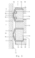
- Fig. 1 shows schematically the structure of a sealing arrangement for a Cylinder-piston system according to the prior art.
- the illustrated cylinder-piston system for example, a part of a Vacuum pump forms, consists essentially of a cylinder (1) and one by means of a piston rod (2) longitudinally displaceable in the cylinder (1) mounted Piston (3).
- each sealing element (5) consists of one on the piston (3) fixedly mounted, statically sealing leg (5a) and a free leg (5b), the dynamic sealing on a cylinder inner wall (1a) of the cylinder (1) is present.
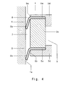
- FIGS. 2 to 5 differ from the prior art according to FIG. 1 im Essentially by the different arrangement of the free leg (5b) of the upper edge (3a) of the piston (3) arranged sealing element (5).
- the dynamic seal causing free leg (5b) at least the am upper, the compression space (4) facing edge (3a) of the piston (3) arranged sealing element (5) facing away from the compression space (4) Direction arranged on the piston (3).
- FIGS. 2 to 5 in comparison with the prior art according to FIG. 1, The embodiments of FIGS. 2 to 5 have the advantage that the material abrasion on the cylinder inner wall (1 a) adjacent free Leg (5b) of the upper, the compression space (4) facing edge (3a) of the piston (3) arranged sealing element (5) has no influence the size of the between the upper edge (3a) of the piston (3) and the cylinder inner wall (1 a) formed dead space (6), since the thinning free legs (5b) in these cases, a gap (7) between the Side wall of the piston (3) and the cylinder inner wall (1a) below the sealing free leg (5b), but not the volume the compression space (4) with influencing dead space (6).
- the sealing elements (5) always arranged in pairs on the piston (3), wherein in the embodiments as shown in FIGS. 2 and 3, the dynamic sealing causing free Leg (5b) of each pair of L-shaped sealing elements (5) to each other attributed to the piston (3) are arranged while these free Leg (5b) in the embodiments according to the illustrations Fig. 4 and 5 in the same, from above the piston (3) arranged compression space (4) pointing direction on the piston (3) are arranged.
- each L-shaped seal member (5) from a rigidly fixedly mounted on the piston (3) leg (5a) for static seal, for example between a piston main body (3c) and a piston cover (3d), and a flexible free leg (5b), the the piston (3) dynamically against the cylinder (1) sealingly on the cylinder inner wall (1a) is present.
- the free legs (5b) of the two sealing elements (5) this seal pair are arranged to each other, that Assign these free legs (5b) to each other.
- the illustrated in Fig. 3 second embodiment of a seal assembly differs from the embodiment described above substantially in that both at the top, the compression space (4) facing Edge (3a) of the piston (3) and at the lower edge (3b) of the piston (3) each one of two sealing elements (5) existing seal pair is arranged.
- the free legs (5b) of the two sealing elements (5) of each pair of seals are in turn arranged in such a way, that these free legs (5b) assign each other.
- the piston edges (3a, 3b) far sealing elements (5) of a each pair of seals piston inserts (3e) are provided on the Leg (5a) of the sealing elements (5) are rigidly fixed to the piston (3).
- additional pressing elements (8) For example, spring rings, provided, which are mounted in grooves (9) in the piston (3) from the piston side to the free legs (5b) abut and this Press against the cylinder inner wall (1 a).
- the upper seal pair has two Pressing elements (8), while the lower seal pair no pressing element (8) is provided.
- the lower seal pair with pressure elements (8) or even to provide only one pressing element (8) in one or both pairs of seals or even form one or both pairs of seals without pressing element.
- the use of a pressure element (8) is advantageous in any case on top, the compression space (4) next sealing element (5) because whose free leg (5b) has the task by a constant sufficient sealing to prevent enlargement of the dead space (6).
- Fig. 5 fourth embodiment of a seal assembly differs from the embodiment described above substantially in that both at the top, the compression space (4) facing Edge (3a) of the piston (3) and at the lower edge (3b) of the piston (3) each one of two sealing elements (5) existing seal pair is arranged.
- the free legs (5b) of the two sealing elements (5) of each pair of seals are in turn arranged in such a way, that these free legs (5b) in the same, from the compression space (4) pointing away Direction are aligned.
- piston inserts (3e) are provided, over which the legs (5a) of the sealing elements (5) are rigidly fixed to the piston (3).
- the upper seal pair two pressing elements (8), while the lower seal pair only a pressing element (8) is provided.
- the lower seal pair with two pressing elements (8) or even a pressing element (8) in one or both pairs of seals provide or even one or both pairs of seals an horrelement arthritis train.
- the use of a pressure element (8) is advantageous. in any case at the top, the compression space (4) next sealing element (5), since its free leg (5b) has the task by a constant adequate sealing an enlargement of the dead space (6) to prevent.
- Embodiments of the seal assemblies can be produced and quite reasonable, the combinations and / or modifications of the illustrated Represent examples. So it is possible, for example, the upper Seal element (5) as shown in Fig. 2 or Fig. 4 form and the lower sealing element (5) as a seal pair according to FIG. 3 or FIG. 5 embody. Likewise, the entire seal arrangement also only a sealing element (5) according to FIG. 2 or 4 at the upper edge (3a) of Piston (3), wherein in all the aforementioned sealing arrangements in turn, the use of pressing elements (8) possible and advantageous is.
- All illustrated and / or only described sealing arrangements are characterized by the fact that the dynamic sealing effecting free legs (5b) at least of the upper, the compression space (4) facing edge (3a) of the piston (3) arranged sealing element (5) arranged in the direction away from the compression space (4) direction on the piston (3) is, so that even with progressive material abrasion of the cylinder inner wall (1a) adjacent free leg (5b) no enlargement of the Dead space (6) takes place.
- each L-shaped sealing element (5) at least in the area of the dynamic seal causing free leg (5b) of a PTFE-containing material.
- Polytetrafluoroethylene (PTFE) is particularly under mechanical pressure load on good sliding properties, so that on this Way high friction losses can be avoided.
- the PTFE-containing material of the free legs (5b) of the L-shaped Sealing elements (5) at least one mechanical resistance contains reinforcing additive, preferably metal, glass, Carbon or plastic materials, in particular knitted aramid fibers, such as Kevlar®, are suitable.
- the pressing elements (8) for example form as spring rings, it may be in these pressing elements (8) also known per se piston rings or rings made of a filled plastic material, in particular a carbon fiber filled epoxy compound, act.
- the sealing effect and contact force of the free legs (5b) of the sealing elements (5) on the cylinder inner wall (1a) of the cylinder (1) is next to the Material Property of the Free Legs (5b) and / or the Pressing Elements (8) determined by the dimensioning of the sealing elements (5).
- the static seal causing legs (5a) of each L-shaped sealing element (5) advantageously a greater thickness than that effecting the dynamic seal, on the cylinder inner wall (1a) fitting free leg (5b) this Sealing element (5), wherein the thickness of the free leg (5b) of each L-shaped sealing element (5) preferably between 0.3 mm and 1 mm is.
- the ratio of the length of the free leg (5b) of each L-shaped Sealing element (5) to the thickness of the piston (3) fixedly mounted Leg (5a) has an influence on the sealing effect of the seal arrangement. So this length to thickness ratio is preferably 5: 1 to 20: 1.
Landscapes
- Engineering & Computer Science (AREA)
- Mechanical Engineering (AREA)
- General Engineering & Computer Science (AREA)
- Compressor (AREA)
- Sealing Devices (AREA)
- Pistons, Piston Rings, And Cylinders (AREA)
Abstract
Description
- 1
- Zylinder
- 1 a
- Zylinderinnenwand
- 2
- Kolbenstange
- 3
- Kolben
- 3a
- oberer Rand
- 3b
- unterer Rand
- 3c
- Kolbengrundkörper
- 3d
- Kolbendeckel
- 3e
- Kolbeneinsatz
- 4
- Kompressionsraum
- 5
- Dichtungselement
- 5a
- Schenkel
- 5b
- freier Schenkel
- 6
- Totraum
- 7
- Zwischenraum
- 8
- Andrückelement
- 9
- Nut
Claims (18)
- Dichtungsanordnung für ein Zylinder-Kolben-System, insbesondere in Vakuumpumpen, zum Abdichten zwischen einer Zylinderinnenwand (1 a) und einem in dem Zylinder (1) verschiebbar gelagerten Kolben (3), mit mindestens einem L-förmig ausgebildeten ringförmigen Dichtungselement (5), wobei ein Schenkel (5a) des L-förmigen Dichtungselements (5) zur statischen Abdichtung am Kolben (3) fixiert gelagert ist und der andere, freie Schenkel (5b) des Dichtungselements (5) dynamisch abdichtend an der Zylinderinnenwand (1 a) anliegt, dadurch gekennzeichnet, dass der die dynamische Abdichtung bewirkende freie Schenkel (5b) zumindest des am oberen, einem Kompressionsraum (4) zugewandten Rand (3a) des Kolbens (3) angeordneten Dichtungselements (5) in die vom Kompressionsraum (4) fortweisende Richtung am Kolben (3) angeordnet ist.
- Dichtungsanordnung nach Anspruch 1, dadurch gekennzeichnet, dass mindestens ein aus jeweils zwei L-förmigen Dichtungselementen (5) bestehendes Dichtungspaar am Kolben (3) angeordnet ist.
- Dichtungsanordnung nach Anspruch 2, dadurch gekennzeichnet, dass die die dynamische Abdichtung bewirkenden freien Schenkel (5b) eines jeden Paares der L-förmigen Dichtungselemente (5) aufeinander zuweisend am Kolben (3) angeordnet sind.
- Dichtungsanordnung nach Anspruch 2, dadurch gekennzeichnet, dass die die dynamische Abdichtung bewirkenden freien Schenkel (5b) eines jeden Paares der L-förmigen Dichtungselemente (5) in die gleiche, vom Kompressionsraum (4) fortweisende Richtung am Kolben (3) angeordnet sind.
- Dichtungsanordnung nach mindestens einem der Ansprüche 2 bis 4, dadurch gekennzeichnet, dass das Dichtungspaar aus einem am oberen, dem Kompressionsraum (4) zugewandten Rand (3a) des Kolbens (3) angeordneten Dichtungselement (5) und einem am unteren Rand (3b) des Kolbens (3) angeordneten Dichtungselement (5) besteht.
- Dichtungsanordnung nach mindestens einem der Ansprüche 2 bis 4, dadurch gekennzeichnet, dass am oberen, dem Kompressionsraum (4) zugewandten Rand (3a) des Kolbens (3) und am unteren Rand (3b) des Kolbens (3) jeweils ein aus zwei Dichtungselementen (5) bestehendes Dichtungspaar angeordnet ist.
- Dichtungsanordnung nach mindestens einem der Ansprüche 1 bis 6, dadurch gekennzeichnet, dass mindestens ein freier Schenkel (5b) eines L-förmigen Dichtungselements (5) über ein am Kolben (3) gelagertes Andrückelement (8) gegen die Zylinderinnenwand (1a) drückbar ist.
- Dichtungsanordnung nach Anspruch 7, dadurch gekennzeichnet, dass das Andrückelement (8) ein in einer ringförmigen Nut (9) des Kolbens (3) gelagerter, an sich bekannter Kolbenring ist.
- Dichtungsanordnung nach Anspruch 7 oder 8, dadurch gekennzeichnet, dass das Andrückelement (8) aus einem gefüllten Kunststoffmaterial, insbesondere einer mit Kohlenstofffasern gefüllten Epoxidverbindung, besteht.
- Dichtungsanordnung nach Anspruch 7, dadurch gekennzeichnet, dass das Andrückelement (8) ein in einer ringförmigen Nut (9) des Kolbens (3) gelagerter Federring ist.
- Dichtungsanordnung nach mindestens einem der Ansprüche 7 bis 10, dadurch gekennzeichnet, dass zumindest der freie Schenkel (5b) des dem oberen, dem Kompressionsraum (4) zugewandten Rand (3a) des Kolbens (3) nächstgelegenen Dichtungselements (5) über das Andrückelement (8) gegen die Zylinderinnenwand (1a) andrückbar ist.
- Dichtungsanordnung nach mindestens einem der Ansprüche 1 bis 13, dadurch gekennzeichnet, dass der am Kolben (3) fixiert gelagerte, die statische Abdichtung bewirkende Schenkel (5a) jedes L-förmigen Dichtungselements (5) eine größere Dicke aufweist als der die dynamische Abdichtung bewirkende, an der Zylinderinnenwand (1a) anliegende freie Schenkel (5b) dieses Dichtungselements (5).
- Dichtungsanordnung nach mindestens einem der Ansprüche 1 bis 12, dadurch gekennzeichnet, dass das Verhältnis der Länge des freien Schenkels (5b) eines jeden L-förmigen Dichtungselements (5) zur Dicke des am Kolben (3) fixiert gelagerten Schenkels (5a) 5:1 bis 20:1 beträgt.
- Dichtungsanordnung nach mindestens einem der Ansprüche 1 bis 13, dadurch gekennzeichnet, dass die Dicke des freien Schenkels (5b) eines jeden L-förmigen Dichtungselements (5) zwischen 0,3 mm und 1 mm beträgt.
- Dichtungsanordnung nach mindestens einem der Ansprüche 1 bis 14,
dadurch gekennzeichnet, dass der Außendurchmesser eines jeden Dichtungselements (5) größer ist als der Innendurchmesser des Zylinders (1 ). - Dichtungsanordnung nach mindestens einem der Ansprüche 1 bis 15, dadurch gekennzeichnet, dass jedes L-förmige Dichtungselement (5) zumindest im Bereich des die dynamische Abdichtung bewirkenden freien Schenkels (5b) aus einem PTFE-haltigen (Polytetrafluorethylen) Material besteht.
- Dichtungsanordnung nach Anspruch 16, dadurch gekennzeichnet, dass das PTFE-haltige Material der freien Schenkel (5b) der L-förmigen Dichtungselemente (5) wenigstens einen die mechanische Beständigkeit verstärkenden Zusatzstoff enthält.
- Dichtungsanordnung nach Anspruch 17, dadurch gekennzeichnet, dass der die mechanische Beständigkeit verstärkenden Zusatzstoff ein Metall-, Glas-, Kohlenstoff- oder Kunststoffmaterial, insbesondere eine gewirkte Aramid-Faser, wie beispielsweise Kevlar ®, ist.
Applications Claiming Priority (2)
| Application Number | Priority Date | Filing Date | Title |
|---|---|---|---|
| DE10337298 | 2003-08-14 | ||
| DE10337298A DE10337298A1 (de) | 2003-08-14 | 2003-08-14 | Dichtungsanordnung für ein Zylinder-Kolben-System |
Publications (2)
| Publication Number | Publication Date |
|---|---|
| EP1508696A1 true EP1508696A1 (de) | 2005-02-23 |
| EP1508696B1 EP1508696B1 (de) | 2006-03-15 |
Family
ID=34042160
Family Applications (1)
| Application Number | Title | Priority Date | Filing Date |
|---|---|---|---|
| EP04016803A Expired - Lifetime EP1508696B1 (de) | 2003-08-14 | 2004-07-16 | Dichtungsanordnung für ein Zylinder-Kolben-System |
Country Status (3)
| Country | Link |
|---|---|
| EP (1) | EP1508696B1 (de) |
| AT (1) | ATE320560T1 (de) |
| DE (2) | DE10337298A1 (de) |
Cited By (4)
| Publication number | Priority date | Publication date | Assignee | Title |
|---|---|---|---|---|
| EP1835178A1 (de) * | 2006-03-18 | 2007-09-19 | Pfeiffer Vacuum GmbH | Dichtungsanordnung für eine Hubkolbenvakuumpumpe |
| CN101806295A (zh) * | 2010-04-22 | 2010-08-18 | 陈人德 | 真空泵的活塞式往复双作用单缸抽气装置 |
| CN102242703A (zh) * | 2010-05-11 | 2011-11-16 | 美克司株式会社 | 摇摆活塞式压缩机 |
| CN105805080A (zh) * | 2016-05-22 | 2016-07-27 | 蚌埠智达科技咨询有限公司 | 一种油缸 |
Families Citing this family (2)
| Publication number | Priority date | Publication date | Assignee | Title |
|---|---|---|---|---|
| DE102009021170A1 (de) * | 2009-05-13 | 2010-12-16 | Compart Compressor Technology Gmbh | Zylinder- und Kolbenstangenabdichtung eines Linearverdichters |
| DE102012202571A1 (de) * | 2012-02-20 | 2013-08-22 | Trelleborg Sealing Solutions Germany Gmbh | Dichtungsanordnung und Verfahren zu dessen Herstellung |
Citations (3)
| Publication number | Priority date | Publication date | Assignee | Title |
|---|---|---|---|---|
| GB2126665A (en) * | 1982-09-11 | 1984-03-28 | Erich Becker | Pump |
| US5921755A (en) * | 1997-04-21 | 1999-07-13 | Dry Vacuum Technologies, Inc. | Dry vacuum pump |
| US6120035A (en) * | 1998-08-26 | 2000-09-19 | Welker Engineering Company | Mating ring seal members with beveled mitered interface |
Family Cites Families (4)
| Publication number | Priority date | Publication date | Assignee | Title |
|---|---|---|---|---|
| US2871071A (en) * | 1955-02-08 | 1959-01-27 | Perfect Circle Corp | Piston ring assembly |
| GB1183900A (en) * | 1968-11-15 | 1970-03-11 | Cross Mfg Co 1938 Ltd | Improvements in Piston-and-Ring Arrangements, particularly for Internal Combustion Engines |
| DE2611999A1 (de) * | 1976-03-20 | 1977-09-29 | Bosch Gmbh Robert | Doppelwirkender kolben |
| JP2003161260A (ja) * | 2001-11-26 | 2003-06-06 | Tokico Ltd | 往復動圧縮機 |
-
2003
- 2003-08-14 DE DE10337298A patent/DE10337298A1/de not_active Withdrawn
-
2004
- 2004-07-16 EP EP04016803A patent/EP1508696B1/de not_active Expired - Lifetime
- 2004-07-16 AT AT04016803T patent/ATE320560T1/de not_active IP Right Cessation
- 2004-07-16 DE DE502004000347T patent/DE502004000347D1/de not_active Expired - Lifetime
Patent Citations (3)
| Publication number | Priority date | Publication date | Assignee | Title |
|---|---|---|---|---|
| GB2126665A (en) * | 1982-09-11 | 1984-03-28 | Erich Becker | Pump |
| US5921755A (en) * | 1997-04-21 | 1999-07-13 | Dry Vacuum Technologies, Inc. | Dry vacuum pump |
| US6120035A (en) * | 1998-08-26 | 2000-09-19 | Welker Engineering Company | Mating ring seal members with beveled mitered interface |
Cited By (8)
| Publication number | Priority date | Publication date | Assignee | Title |
|---|---|---|---|---|
| EP1835178A1 (de) * | 2006-03-18 | 2007-09-19 | Pfeiffer Vacuum GmbH | Dichtungsanordnung für eine Hubkolbenvakuumpumpe |
| CN101806295A (zh) * | 2010-04-22 | 2010-08-18 | 陈人德 | 真空泵的活塞式往复双作用单缸抽气装置 |
| CN101806295B (zh) * | 2010-04-22 | 2013-04-03 | 陈人德 | 真空泵的活塞式往复双作用单缸抽气装置 |
| CN102242703A (zh) * | 2010-05-11 | 2011-11-16 | 美克司株式会社 | 摇摆活塞式压缩机 |
| US9255477B2 (en) | 2010-05-11 | 2016-02-09 | Max Co., Ltd. | Rocking piston type compressor |
| CN102242703B (zh) * | 2010-05-11 | 2016-08-03 | 美克司株式会社 | 摇摆活塞式压缩机 |
| CN105805080A (zh) * | 2016-05-22 | 2016-07-27 | 蚌埠智达科技咨询有限公司 | 一种油缸 |
| CN105805080B (zh) * | 2016-05-22 | 2017-11-07 | 蚌埠智达科技咨询有限公司 | 一种油缸 |
Also Published As
| Publication number | Publication date |
|---|---|
| DE502004000347D1 (de) | 2006-05-11 |
| ATE320560T1 (de) | 2006-04-15 |
| EP1508696B1 (de) | 2006-03-15 |
| DE10337298A1 (de) | 2005-03-03 |
Similar Documents
| Publication | Publication Date | Title |
|---|---|---|
| DE4205862C1 (de) | ||
| EP0985108B1 (de) | Dichtelement für trockenlaufsysteme und verwendung eines solchen dichtelements | |
| EP2912351B1 (de) | Kolbenring | |
| DE2847274C2 (de) | Kolben für einen Arbeitszylinder | |
| DE102020211680A1 (de) | Kolben-Zylinder-Baugruppe für einen Radialkolbenverdichter sowie Radialkolbenverdichter | |
| EP0832383B1 (de) | Dichtungsanordnung | |
| WO2015128142A2 (de) | Schwingungsdämpfer mit einem endanschlag | |
| DE2211178A1 (de) | Dichtungssatz und diesen enthaltende Dichtungsgruppe für Hochdruckpumpen od. dgl | |
| DE2829352A1 (de) | Zusammengesetzter bzw. verbunddichtring, insbesondere fuer eine stirling-maschine | |
| EP3387256A1 (de) | Doppelkolbenkompressor einer druckluft-versorgungseinrichtung | |
| EP3919784A1 (de) | Kolbenringanordnung | |
| EP1835178B1 (de) | Dichtungsanordnung für eine Hubkolbenvakuumpumpe | |
| DE102017129539A1 (de) | Federhülse, Zylinder, Kolbenzylindereinheit und Verfahren zur Herstellung einer Kolbenzylindereinheit | |
| EP1508696B1 (de) | Dichtungsanordnung für ein Zylinder-Kolben-System | |
| EP4118365A1 (de) | Kolbenringanordnung, kolbenverdichter sowie verfarhen zum abdichten eines verdichtungsraums | |
| DE102007060014A1 (de) | Drehgleitlager mit einer balligen und einer elastisch-nachgiebigen Gleitfläche | |
| DE102005018442A1 (de) | Hydraulische Zylindereinheit | |
| DE102012024121A1 (de) | Dichtring, Dichtungsanordnung und deren Verwendung | |
| DE4122481C2 (de) | Kolben-Zylinder-Anordnung | |
| DE102015015946A1 (de) | Doppelkolbenkompressor einer Druckluft-Versorgungseinrichtung | |
| DE60210281T2 (de) | Hermetischer Kolbenverdichter | |
| EP0832382A1 (de) | Dichtungsring | |
| DE2609817B2 (de) | Kolben, insbesondere für einen Pneumatikzylinder | |
| WO2006005330A1 (de) | Dichtungsanordnung | |
| DE102011018407A1 (de) | Kolben- und Zylinderanordnung |
Legal Events
| Date | Code | Title | Description |
|---|---|---|---|
| PUAI | Public reference made under article 153(3) epc to a published international application that has entered the european phase |
Free format text: ORIGINAL CODE: 0009012 |
|
| AK | Designated contracting states |
Kind code of ref document: A1 Designated state(s): AT BE BG CH CY CZ DE DK EE ES FI FR GB GR HU IE IT LI LU MC NL PL PT RO SE SI SK TR |
|
| AX | Request for extension of the european patent |
Extension state: AL HR LT LV MK |
|
| GRAP | Despatch of communication of intention to grant a patent |
Free format text: ORIGINAL CODE: EPIDOSNIGR1 |
|
| 17P | Request for examination filed |
Effective date: 20050729 |
|
| AKX | Designation fees paid |
Designated state(s): AT BE BG CH CY CZ DE DK EE ES FI FR GB GR HU IE IT LI LU MC NL PL PT RO SE SI SK TR |
|
| GRAS | Grant fee paid |
Free format text: ORIGINAL CODE: EPIDOSNIGR3 |
|
| GRAA | (expected) grant |
Free format text: ORIGINAL CODE: 0009210 |
|
| AK | Designated contracting states |
Kind code of ref document: B1 Designated state(s): AT BE BG CH CY CZ DE DK EE ES FI FR GB GR HU IE IT LI LU MC NL PL PT RO SE SI SK TR |
|
| PG25 | Lapsed in a contracting state [announced via postgrant information from national office to epo] |
Ref country code: SI Free format text: LAPSE BECAUSE OF FAILURE TO SUBMIT A TRANSLATION OF THE DESCRIPTION OR TO PAY THE FEE WITHIN THE PRESCRIBED TIME-LIMIT Effective date: 20060315 Ref country code: IE Free format text: LAPSE BECAUSE OF FAILURE TO SUBMIT A TRANSLATION OF THE DESCRIPTION OR TO PAY THE FEE WITHIN THE PRESCRIBED TIME-LIMIT Effective date: 20060315 Ref country code: RO Free format text: LAPSE BECAUSE OF FAILURE TO SUBMIT A TRANSLATION OF THE DESCRIPTION OR TO PAY THE FEE WITHIN THE PRESCRIBED TIME-LIMIT Effective date: 20060315 Ref country code: FI Free format text: LAPSE BECAUSE OF FAILURE TO SUBMIT A TRANSLATION OF THE DESCRIPTION OR TO PAY THE FEE WITHIN THE PRESCRIBED TIME-LIMIT Effective date: 20060315 Ref country code: SK Free format text: LAPSE BECAUSE OF FAILURE TO SUBMIT A TRANSLATION OF THE DESCRIPTION OR TO PAY THE FEE WITHIN THE PRESCRIBED TIME-LIMIT Effective date: 20060315 Ref country code: PL Free format text: LAPSE BECAUSE OF FAILURE TO SUBMIT A TRANSLATION OF THE DESCRIPTION OR TO PAY THE FEE WITHIN THE PRESCRIBED TIME-LIMIT Effective date: 20060315 |
|
| REG | Reference to a national code |
Ref country code: GB Ref legal event code: FG4D Free format text: NOT ENGLISH Ref country code: CH Ref legal event code: EP |
|
| REG | Reference to a national code |
Ref country code: IE Ref legal event code: FG4D Free format text: LANGUAGE OF EP DOCUMENT: GERMAN |
|
| REG | Reference to a national code |
Ref country code: CH Ref legal event code: NV Representative=s name: PFEIFFER VACUUM (SCHWEIZ) AG |
|
| REF | Corresponds to: |
Ref document number: 502004000347 Country of ref document: DE Date of ref document: 20060511 Kind code of ref document: P |
|
| PG25 | Lapsed in a contracting state [announced via postgrant information from national office to epo] |
Ref country code: DK Free format text: LAPSE BECAUSE OF FAILURE TO SUBMIT A TRANSLATION OF THE DESCRIPTION OR TO PAY THE FEE WITHIN THE PRESCRIBED TIME-LIMIT Effective date: 20060615 Ref country code: SE Free format text: LAPSE BECAUSE OF FAILURE TO SUBMIT A TRANSLATION OF THE DESCRIPTION OR TO PAY THE FEE WITHIN THE PRESCRIBED TIME-LIMIT Effective date: 20060615 Ref country code: BG Free format text: LAPSE BECAUSE OF FAILURE TO SUBMIT A TRANSLATION OF THE DESCRIPTION OR TO PAY THE FEE WITHIN THE PRESCRIBED TIME-LIMIT Effective date: 20060615 |
|
| PG25 | Lapsed in a contracting state [announced via postgrant information from national office to epo] |
Ref country code: ES Free format text: LAPSE BECAUSE OF FAILURE TO SUBMIT A TRANSLATION OF THE DESCRIPTION OR TO PAY THE FEE WITHIN THE PRESCRIBED TIME-LIMIT Effective date: 20060626 |
|
| GBT | Gb: translation of ep patent filed (gb section 77(6)(a)/1977) |
Effective date: 20060615 |
|
| PG25 | Lapsed in a contracting state [announced via postgrant information from national office to epo] |
Ref country code: MC Free format text: LAPSE BECAUSE OF NON-PAYMENT OF DUE FEES Effective date: 20060731 Ref country code: BE Free format text: LAPSE BECAUSE OF NON-PAYMENT OF DUE FEES Effective date: 20060731 |
|
| PG25 | Lapsed in a contracting state [announced via postgrant information from national office to epo] |
Ref country code: PT Free format text: LAPSE BECAUSE OF FAILURE TO SUBMIT A TRANSLATION OF THE DESCRIPTION OR TO PAY THE FEE WITHIN THE PRESCRIBED TIME-LIMIT Effective date: 20060816 |
|
| REG | Reference to a national code |
Ref country code: IE Ref legal event code: FD4D |
|
| ET | Fr: translation filed | ||
| PLBE | No opposition filed within time limit |
Free format text: ORIGINAL CODE: 0009261 |
|
| STAA | Information on the status of an ep patent application or granted ep patent |
Free format text: STATUS: NO OPPOSITION FILED WITHIN TIME LIMIT |
|
| 26N | No opposition filed |
Effective date: 20061218 |
|
| PG25 | Lapsed in a contracting state [announced via postgrant information from national office to epo] |
Ref country code: AT Free format text: LAPSE BECAUSE OF NON-PAYMENT OF DUE FEES Effective date: 20060716 |
|
| BERE | Be: lapsed |
Owner name: PFEIFFER VACUUM G.M.B.H. Effective date: 20060731 |
|
| PG25 | Lapsed in a contracting state [announced via postgrant information from national office to epo] |
Ref country code: CZ Free format text: LAPSE BECAUSE OF FAILURE TO SUBMIT A TRANSLATION OF THE DESCRIPTION OR TO PAY THE FEE WITHIN THE PRESCRIBED TIME-LIMIT Effective date: 20060315 Ref country code: GR Free format text: LAPSE BECAUSE OF FAILURE TO SUBMIT A TRANSLATION OF THE DESCRIPTION OR TO PAY THE FEE WITHIN THE PRESCRIBED TIME-LIMIT Effective date: 20060616 |
|
| PG25 | Lapsed in a contracting state [announced via postgrant information from national office to epo] |
Ref country code: EE Free format text: LAPSE BECAUSE OF FAILURE TO SUBMIT A TRANSLATION OF THE DESCRIPTION OR TO PAY THE FEE WITHIN THE PRESCRIBED TIME-LIMIT Effective date: 20060315 |
|
| PG25 | Lapsed in a contracting state [announced via postgrant information from national office to epo] |
Ref country code: TR Free format text: LAPSE BECAUSE OF FAILURE TO SUBMIT A TRANSLATION OF THE DESCRIPTION OR TO PAY THE FEE WITHIN THE PRESCRIBED TIME-LIMIT Effective date: 20060315 Ref country code: LU Free format text: LAPSE BECAUSE OF NON-PAYMENT OF DUE FEES Effective date: 20060716 Ref country code: HU Free format text: LAPSE BECAUSE OF FAILURE TO SUBMIT A TRANSLATION OF THE DESCRIPTION OR TO PAY THE FEE WITHIN THE PRESCRIBED TIME-LIMIT Effective date: 20060916 |
|
| PG25 | Lapsed in a contracting state [announced via postgrant information from national office to epo] |
Ref country code: CY Free format text: LAPSE BECAUSE OF FAILURE TO SUBMIT A TRANSLATION OF THE DESCRIPTION OR TO PAY THE FEE WITHIN THE PRESCRIBED TIME-LIMIT Effective date: 20060315 |
|
| PGFP | Annual fee paid to national office [announced via postgrant information from national office to epo] |
Ref country code: NL Payment date: 20100421 Year of fee payment: 7 |
|
| REG | Reference to a national code |
Ref country code: NL Ref legal event code: V1 Effective date: 20120201 |
|
| PG25 | Lapsed in a contracting state [announced via postgrant information from national office to epo] |
Ref country code: NL Free format text: LAPSE BECAUSE OF NON-PAYMENT OF DUE FEES Effective date: 20120201 |
|
| PGFP | Annual fee paid to national office [announced via postgrant information from national office to epo] |
Ref country code: FR Payment date: 20120716 Year of fee payment: 9 |
|
| PGFP | Annual fee paid to national office [announced via postgrant information from national office to epo] |
Ref country code: GB Payment date: 20130710 Year of fee payment: 10 |
|
| PGFP | Annual fee paid to national office [announced via postgrant information from national office to epo] |
Ref country code: IT Payment date: 20130729 Year of fee payment: 10 |
|
| REG | Reference to a national code |
Ref country code: FR Ref legal event code: ST Effective date: 20140331 |
|
| PG25 | Lapsed in a contracting state [announced via postgrant information from national office to epo] |
Ref country code: FR Free format text: LAPSE BECAUSE OF NON-PAYMENT OF DUE FEES Effective date: 20130731 |
|
| GBPC | Gb: european patent ceased through non-payment of renewal fee |
Effective date: 20140716 |
|
| PG25 | Lapsed in a contracting state [announced via postgrant information from national office to epo] |
Ref country code: IT Free format text: LAPSE BECAUSE OF NON-PAYMENT OF DUE FEES Effective date: 20140716 |
|
| PG25 | Lapsed in a contracting state [announced via postgrant information from national office to epo] |
Ref country code: GB Free format text: LAPSE BECAUSE OF NON-PAYMENT OF DUE FEES Effective date: 20140716 |
|
| PGFP | Annual fee paid to national office [announced via postgrant information from national office to epo] |
Ref country code: DE Payment date: 20170804 Year of fee payment: 14 |
|
| REG | Reference to a national code |
Ref country code: DE Ref legal event code: R119 Ref document number: 502004000347 Country of ref document: DE |
|
| PG25 | Lapsed in a contracting state [announced via postgrant information from national office to epo] |
Ref country code: DE Free format text: LAPSE BECAUSE OF NON-PAYMENT OF DUE FEES Effective date: 20190201 |
|
| PGFP | Annual fee paid to national office [announced via postgrant information from national office to epo] |
Ref country code: CH Payment date: 20200122 Year of fee payment: 16 |
|
| REG | Reference to a national code |
Ref country code: CH Ref legal event code: PL |
|
| PG25 | Lapsed in a contracting state [announced via postgrant information from national office to epo] |
Ref country code: CH Free format text: LAPSE BECAUSE OF NON-PAYMENT OF DUE FEES Effective date: 20200731 Ref country code: LI Free format text: LAPSE BECAUSE OF NON-PAYMENT OF DUE FEES Effective date: 20200731 |