EP1508461A1 - Hydropneumatische Federungseinrichtung - Google Patents
Hydropneumatische Federungseinrichtung Download PDFInfo
- Publication number
- EP1508461A1 EP1508461A1 EP04103655A EP04103655A EP1508461A1 EP 1508461 A1 EP1508461 A1 EP 1508461A1 EP 04103655 A EP04103655 A EP 04103655A EP 04103655 A EP04103655 A EP 04103655A EP 1508461 A1 EP1508461 A1 EP 1508461A1
- Authority
- EP
- European Patent Office
- Prior art keywords
- pressure
- valve
- proportional
- annular space
- tank
- Prior art date
- Legal status (The legal status is an assumption and is not a legal conclusion. Google has not performed a legal analysis and makes no representation as to the accuracy of the status listed.)
- Granted
Links
- 239000000725 suspension Substances 0.000 title claims description 51
- 239000007788 liquid Substances 0.000 claims description 18
- 230000000903 blocking effect Effects 0.000 claims description 4
- 239000000446 fuel Substances 0.000 claims 2
- 230000000712 assembly Effects 0.000 abstract 1
- 238000000429 assembly Methods 0.000 abstract 1
- 230000001960 triggered effect Effects 0.000 abstract 1
- 230000008901 benefit Effects 0.000 description 8
- 239000012530 fluid Substances 0.000 description 7
- 238000011161 development Methods 0.000 description 3
- 230000018109 developmental process Effects 0.000 description 3
- 230000005281 excited state Effects 0.000 description 3
- 230000001105 regulatory effect Effects 0.000 description 3
- 230000007423 decrease Effects 0.000 description 2
- 230000036316 preload Effects 0.000 description 2
- 230000009467 reduction Effects 0.000 description 2
- 241000243251 Hydra Species 0.000 description 1
- 230000006978 adaptation Effects 0.000 description 1
- 230000033228 biological regulation Effects 0.000 description 1
- 230000008859 change Effects 0.000 description 1
- 238000004891 communication Methods 0.000 description 1
- 230000001276 controlling effect Effects 0.000 description 1
- 230000001419 dependent effect Effects 0.000 description 1
- 238000013461 design Methods 0.000 description 1
- 238000010586 diagram Methods 0.000 description 1
- 239000002828 fuel tank Substances 0.000 description 1
- QRXWMOHMRWLFEY-UHFFFAOYSA-N isoniazide Chemical compound NNC(=O)C1=CC=NC=C1 QRXWMOHMRWLFEY-UHFFFAOYSA-N 0.000 description 1
- 238000000034 method Methods 0.000 description 1
- 238000012986 modification Methods 0.000 description 1
- 230000004048 modification Effects 0.000 description 1
Images

Classifications
-
- B—PERFORMING OPERATIONS; TRANSPORTING
- B60—VEHICLES IN GENERAL
- B60G—VEHICLE SUSPENSION ARRANGEMENTS
- B60G21/00—Interconnection systems for two or more resiliently-suspended wheels, e.g. for stabilising a vehicle body with respect to acceleration, deceleration or centrifugal forces
- B60G21/02—Interconnection systems for two or more resiliently-suspended wheels, e.g. for stabilising a vehicle body with respect to acceleration, deceleration or centrifugal forces permanently interconnected
- B60G21/06—Interconnection systems for two or more resiliently-suspended wheels, e.g. for stabilising a vehicle body with respect to acceleration, deceleration or centrifugal forces permanently interconnected fluid
-
- B—PERFORMING OPERATIONS; TRANSPORTING
- B60—VEHICLES IN GENERAL
- B60G—VEHICLE SUSPENSION ARRANGEMENTS
- B60G17/00—Resilient suspensions having means for adjusting the spring or vibration-damper characteristics, for regulating the distance between a supporting surface and a sprung part of vehicle or for locking suspension during use to meet varying vehicular or surface conditions, e.g. due to speed or load
- B60G17/02—Spring characteristics, e.g. mechanical springs and mechanical adjusting means
- B60G17/04—Spring characteristics, e.g. mechanical springs and mechanical adjusting means fluid spring characteristics
- B60G17/056—Regulating distributors or valves for hydropneumatic systems
-
- B—PERFORMING OPERATIONS; TRANSPORTING
- B60—VEHICLES IN GENERAL
- B60G—VEHICLE SUSPENSION ARRANGEMENTS
- B60G2202/00—Indexing codes relating to the type of spring, damper or actuator
- B60G2202/10—Type of spring
- B60G2202/15—Fluid spring
- B60G2202/154—Fluid spring with an accumulator
-
- B—PERFORMING OPERATIONS; TRANSPORTING
- B60—VEHICLES IN GENERAL
- B60G—VEHICLE SUSPENSION ARRANGEMENTS
- B60G2202/00—Indexing codes relating to the type of spring, damper or actuator
- B60G2202/40—Type of actuator
- B60G2202/41—Fluid actuator
- B60G2202/413—Hydraulic actuator
-
- B—PERFORMING OPERATIONS; TRANSPORTING
- B60—VEHICLES IN GENERAL
- B60G—VEHICLE SUSPENSION ARRANGEMENTS
- B60G2202/00—Indexing codes relating to the type of spring, damper or actuator
- B60G2202/40—Type of actuator
- B60G2202/41—Fluid actuator
- B60G2202/414—Fluid actuator using electrohydraulic valves
-
- B—PERFORMING OPERATIONS; TRANSPORTING
- B60—VEHICLES IN GENERAL
- B60G—VEHICLE SUSPENSION ARRANGEMENTS
- B60G2500/00—Indexing codes relating to the regulated action or device
- B60G2500/02—Supply or exhaust flow rates; Pump operation
Definitions
- the invention relates to a hydropneumatic Suspension device with at least one hydraulic Suspension cylinder, the cylinder space and annulus each with at least one pressure accumulator in connection and means Valve arrangements optionally with a pressure source and a Tank are connectable.
- the suspension device should preferably be sprung Wheel suspensions of vehicles, in particular of agricultural or industrial vehicles, applied become.
- the suspension can be a Independent suspension or the sprung suspension of a Act vehicle axle.
- the at least one suspension cylinder is between vehicle body and wheel or vehicle axle arranged.
- the design of a hydropneumatic suspension is especially in agricultural or industrial Working machines, such as tractors, a special one Challenge because extreme axle load variations are possible here are.
- the axle load bandwidth usually exceeds that at Diaphragm storage possible pressure ratio.
- To the Work area of the pressure accumulator is to be able to therefore biased the system. This bias acts like a additional axle load, reducing the ratio of minimum to maximum axle load can be reduced.
- the bias of the system is rarely over one mechanical preload, which is also an easy acting cylinder can be used.
- a double-acting hydraulic cylinder is used in the the annulus side via a pressure accumulator with a is biased to certain pressure.
- the set on the annulus side pressure can either the maximum system pressure correspond (DE-A-43 08 460) or Pressure is regulated by a pressure regulator preselected value (DE-C-42 42 448).
- Both Methods like any hydropneumatic system, are inherent, that the spring rate according to a given function in Essentially square depends on the axle load. For one constant build-up natural frequency, however, would be a linear one Dependence ideal.
- DE-A-41 20 758 is a hydropneumatic vehicle suspension of the type mentioned above, in the adaptation to large Achslastsp Dahl in the supply line to the annulus hydraulically operated control valve is arranged, the on the one hand the pressure in the annulus and on the other hand the pressure the cylinder space is exposed, so that the pressure in Annular space regulated as a function of the pressure in the cylinder space becomes. This is to a higher spring stiffness in the area be reached smaller axle loads.
- a certain axle load can be different Ballast istszuident be generated on the vehicle.
- the weight of a heavy plow balance and provide sufficient load on the front axle bring ballast weights at the front of the tractor assemble.
- this ballast can be the same Axle load at the front axle results like a tractor, the equipped with neither a plow nor with front weights.
- the spring stiffness can not be different Ballast conditions and working or driving conditions of Vehicle react, d. H. the spring stiffness is independent from these states and depends only on each one prevailing axle load. This can be done, for example cause a heavily ballasted tractor with respect to the Nickeigenfrequenz is softly sprung during the Unballasted tractor is too hard.
- a hydropneumatic suspension device of the beginning specify the type mentioned by which the aforementioned Problems are overcome.
- a given unchanging quadratic dependence of the spring rate of the axle load to be countered and the spring rate should Ballast conditions and working or driving conditions of Vehicle adaptable and not just from the current Suspend axle load.
- the hydropneumatic suspension device contains at least one hydraulic suspension cylinder, in particular a double-acting hydraulic cylinder whose Cylinder space and annulus each with at least one Pressure accumulator in connection.
- the suspension cylinder can for example, between the chassis of a vehicle and its Wheel or axle be arranged.
- valve arrangements let the cylinder space and the annulus be independent from each other to a pressure source and to a tank.
- This suspension device is characterized in that the annulus assigned valve assembly at least one especially in a no-current position closed seat-tight first solenoid valve and arranged in series therewith electrically controllable the pressure setting serving Proportional valve has.
- the annulus pressure either directly as Control pressure applied to the proportional valve or through Using a sensor detected and to control the Proportional valve are used.
- a sensor detected and to control the Proportional valve are used.
- the Sensor signals are used to control the proportional valve used.
- the proportional valve hydraulically in To control dependence of the annulus pressure.
- the Proportional valve is on the one hand the pressure of his On the other hand, the pressure of his tank-side connection suspended.
- the solenoid valve is preferably between the annulus and the proportional valve. It ensures that in his Closed position the smallest possible leakage from the Annular space side to the tank occurs. In its closed position is a check valve is effective. Suitable solenoid valves with Extremely low leakage, for example, as models SV08-20 and SV08-22 by Hydra Force, Lincolnshire, IL, USA offered.
- the adjustment of the annulus pressure is done via the Proportional valve.
- About the control current of the Proportional valve controlling magnets can be a specific Pressure to be preselected, which then on the annulus side of the Spring circuit is set.
- the setting of the Control current for example, by a control unit and due to different parameters, such as ballast, driving speed and operating conditions, respectively.
- the suspension device usually also over It is a level control with a position sensor also possible, the strength of the positioner detected impacts, which from the ground on the tires be taken into account in the control.
- this suspension device can the annular space side Change the preload of the axle suspension within wide limits.
- the annulus pressure and thus the Suspension characteristic within given physical Set limits arbitrarily, so that on the one hand a fixed quadratic dependence of the spring rate on the axle load be met and z. B. a more linear Spring characteristic can be adjusted.
- the suspension device according to the invention by suitable electrical control of the proportional valve different ballast conditions, speeds and Operating conditions of the vehicle respond.
- the Suspension characteristics can thus be automatically and on optimal way individually to different driving and Adjust work assignments. It is emphasized that to Actuation of the proportional valve no through the Control unit detected pressure sensor signal is required, even if in special applications the use of a Pressure sensor signal may be appropriate.
- the first solenoid valve includes in its closed (switched off, de-energized) position one Non-return valve function, which eliminates liquid from the Annular space prevented.
- the seat-tight check valve provides in particularly effective way that when switched off Proportional valve leakage from the annulus side of the Hydraulic cylinder to the tank is omitted.
- the first solenoid valve in its closed (shut off) position two check valve functions contains a fluid flow in both directions prevented.
- the first solenoid valve and the proportional valve In many applications it is of particular advantage between the first solenoid valve and the proportional valve to arrange a flow limiting orifice.
- the aperture allows a controlled adjustment of the annulus pressure.
- the annulus pressure by a slow regulation of the proportional valve controlled adjust so that the panel is completely dispensed with can.
- the use of a diaphragm can still in Be associated with a load-sensing control advantageous.
- a flow resistance is considered below which can be designed in different ways, For example, as a local constriction (aperture) or as extending over a longer flow path constriction (Throttle).
- Proportional valve an electromagnetically controllable Proportional pressure control valve, which its annular space side Connection with either the tank or the pressure source combines.
- Suitable proportional pressure control valves are for example as model TS98-31 by the company HydraForce, Lincolnshire, IL, United States.
- the proportional pressure control valve connects in de-energized position its annular space-side connection with his tankside connection (gas station position) and in the excited State its pressure-source-side connection with the Annular space connection (pressure source position).
- the Proportional pressure control valve pushes into its fuel tank position, so that its annular space-side connection in a de-energized state always connected to the tank.
- a further preferred embodiment of the invention becomes an electromagnetic as an alternative to the proportional pressure control valve controllable proportional pressure relief valve used.
- This valve optionally provides a connection between his annulus side port and the tank ago.
- Suitable proportional pressure relief valves for example as model TS08-27 by the company HydraForce, Lincolnshire, IL, United States.
- the proportional pressure limiting valve connects in the excited state its annular space connection with its tank side connection (fueling position) and locks in de-energized state this connection (blocking position).
- a return spring is provided, which is the Proportional pressure limiting valve in its blocking position urges, so that its annular space-side connection in de-energized Condition is always connected to the tank.
- the proportional pressure relief valve controls only the Connection between the annulus side and the tank. To the Apply pressure to the annulus side with the pressure of the pressure source To be able to do that, it is of particular advantage that of the between the solenoid valve and the proportional pressure relief valve extending line one with the pressure source in connection branches off the pressure line.
- the pressure on the annulus side to a desired To limit value, it is appropriate in the pressure line a To arrange pressure line diaphragm. This allows a permanent limited fluid flow from the pressure source to Annulus side. Through the proportional pressure relief valve However, the pressure on the annulus side is limited because of it when exceeding one based on the electrical control adjustable annular space pressure opens.
- a second Solenoid valve is arranged.
- this contains Solenoid valve in its closed position one Check valve function, which is a liquid flow from the Prevents pressure source from leaving, so that no or only one negligible small leakage from the pressure source to Ring space side is given.
- Check valve function which is a liquid flow from the Prevents pressure source from leaving, so that no or only one negligible small leakage from the pressure source to Ring space side is given.
- the pressure line aperture omitted.
- the pressure source is expediently a hydraulic pump. It For example, it may be a hydraulic pump that already for other hydraulic consumers of the vehicle Available. To use the hydraulic pump economically To be able to, is often a pump with a load-sensing function used at the required system pressure for Control of the pump is used.
- the hydraulic pump promotes hydraulic fluid only when required and leaves otherwise in a low-power stand-by mode over.
- the Control connection of the load-sensing pump via a control line with the proportional valve facing port of the first Solenoid valve to connect. If the at this connection prevailing pressure through the proportional valve to the tank is degraded (not energized position of the valve) exists no pressure medium requirement and the load-sensing pump goes into their Stand-by operation over. A pressure reduction from the annulus of the Hydraulic cylinder is here by the first solenoid valve prevented.
- the annular space side increases Pressure on (either via a pressure line or because the Proportional valve connects to the pressure source creates). This pressure increase is by the load-sensing pump perceived, which swings out and their output pressure so he always sets, for example, 30 bar above the annular space-side pressure is.
- valves of the suspension device according to the invention summarized in a common control block.
- this control block can also be a valve assembly for Level control, which the liquid inflow and outflow on the Cylinder room side controls, be integrated.
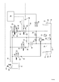
- the vehicle suspension system shown in Fig. 1 is for Suspension of a steerable, pendulum-suspended, not closer Tractor front axle shown determined. It contains two Cylinder 10, 12.
- the two cylinder chambers 14, 16 of the Hydraulic cylinder 10, 12 and the two annular spaces 18, 20 of the two hydraulic cylinders 10, 12 are each about Hydraulic lines 22, 24 with each other and with an associated Hydraulic accumulator 26, 28 connected.
- the cylinder space side hydraulic line 22 (cylinder chamber side the spring circuit) is via a first aperture 30 and a first seat-tight switching valve 32 with a liquid container or Tank 34 connected.
- the first switching valve 32 can be through electrical signals between a flow position and a Lock position, which ensures that no liquid inadvertently from the cylinder room side of the Federnikes to tank 34 can escape, switch.
- the cylinder space-side hydraulic line 22 is further over a check valve 36, a second orifice 38 and a second one seat-tight switching valve 40 with a pressure source in which it is a controllable load-sensing pump 42, connected.
- the second switching valve 40 can be through electrical signals between a flow position and a Lock position, which ensures that no liquid inadvertently from the hydraulic pump 42 in the Spring circuit arrives, switch over.
- the check valve 36 locks the liquid flow in the opposite way as the second Switching valve 40 to prevent leakage when the pressure in the cylinder chamber side of the spring circuit is greater than the Pressure of the supply line 44.
- This valve arrangement serves the level control.
- the first switching valve 32 energized
- its slide switches to the "open" position and Hydraulic fluid flows out of the cylinder chamber side Hydraulic line 22 controlled via the first panel 30 to Tank 34.
- the second Switching valve 40 is opened, the liquid flows from first the supply line 44 via the second aperture 38 in a Load-sensing line 46 and reports via a shuttle valve 48th the pressure medium requirement to the control terminal 43 of the Hydraulic pump 42. This regulates the pressure until, until the check valve 36 opens and liquid in the Cylinder-space-side hydraulic line 22 flows.
- the volume flow is limited, on the other hand also produces a pressure drop, so that the Load-sensing system always on the cylinder room side prevailing pressure is reported.
- the pump 42 pivots not full, but always provides a pressure that z. B. 30 bar above the cylinder space pressure.
- the second switching valve 40 is open Volume flow through a third aperture 50 back to the tank 34th This additional, provided by the third panel 50 Cross-section is needed to close the second one Switching valve 40 the load-sensing pressure to the tank 34 toward relieve.
- first switching valve 32 and the first orifice 30 and the second switching valve 40 and the second aperture 38 also each a proportionally controlled, seat-tight 2/2-way switching valve can be used which can be opened by a controlled amount of current controlled.
- the cylinder chamber side of the spring circuit namely the Hydraulic line 22 is connected via a pressure limiting valve 52 a certain maximum pressure, usually from the Save is determined, secured.
- a drain valve 54 is used in service case, the cylinder chamber side of the pressure to relieve.
- a Inventive suspension device This consists according to Fig. 1 essentially of an electrically adjustable Proportional pressure control valve 60, a diaphragm 62 and a electrically switchable solenoid valve 64, which one behind the other are arranged, wherein the solenoid valve 64 with the annular space-side hydraulic line 24 is in communication and the proportional pressure control valve 60 an optional connection with the pump 42 or with the tank 34 allows.
- the slider the proportional pressure control valve 60 is on the one hand via a Control line 65 the pressure of its annular space-side connection 66 and on the other hand via a control line 67 the pressure of Tank line 68 exposed, in such a way that the Annular pressure together with the force of a Return spring 69 of the force of the electromagnet 70th counteracts.
- the seat-tight solenoid valve 64 opens in the energized state against the force of a return spring 63 a Flow opening, which in the de-energized state such is closed, that a liquid drain from the annular space-side hydraulic line 24 reliably prevented becomes.
- the solenoid valve 64 is for example a seat-tight 2/2 way valve. It can also be a act electromagnetically controllable proportional valve, where appropriate, can be dispensed with the aperture 62.
- the seat-tight solenoid valve 64 ensures that when switched off Proportional pressure control valve 60 as low as possible leakage from the annulus side of the spring circuit to the tank 34 occurs. Since the proportional pressure control valve 60 de-energized the Consumer switches to the tank 34, it makes it possible closed solenoid valve 64 also that the load-sensing pressure via the proportional pressure control valve 60 to the tank 34 out can be broken down without leaving the liquid The annular space-side hydraulic line 24 flows.
- the attitude the annulus pressure is controlled via the aperture 62nd and, if necessary, a slow upset of the Proportional pressure control valve 60 (in the latter case could may be waived on the aperture).
- a slow upset of the Proportional pressure control valve 60 in the latter case could may be waived on the aperture.
- a drain valve 74 is in Service case used to the annulus side of the pressure to relieve.
- unlockable check valve instead of the solenoid valve 64 and the Use of a seat-tight, unlockable check valve possible.
- the unlocking can in this case z. B. over a Pressure is done on the page for the level control decreases.
- the two switching valves 32, 40, the Proportional pressure control valve 60 and the solenoid valve 64 are controlled by an electrical control unit 76.
- the Control unit 76 receives signals from a not shown Position transmitter, which is used for the level control by means of Switching valves 32, 40 are used.
- a not shown Position transmitter which is used for the level control by means of Switching valves 32, 40 are used.
- the control unit 76 evaluates the control unit 76 also measured values of a not shown Vehicle speed sensor and a tensile force sensor.
- the spring stiffness can thus be automatically in Dependence of the vehicle speed and / or thereof adjust whether a device is attached to the vehicle or is mounted, which is closed from the tension sensor signal can be.
- the control unit 76 may, if appropriate is also signals of a rear and / or front PTO or receive and evaluate other vehicle aggregates.
- the Ballasting of the vehicle can be achieved through the Operator, for example, using a switch pretend. It is also detected by the control unit and for adjusting the proportional pressure control valve 60 evaluated.
- the above and other signals can the Control unit 76, for example via a CAN-BUS for Will be provided.
- a pressure sensor 78 to the connected to the annular space side hydraulic line 24, whose Signals are evaluated by the control unit 76 and the Adjustment of the proportional pressure control valve 60 used become.
- the pressure sensor 78 may also be Proportional pressure control valve can be used, the pure electrical (and not hydraulic) is controlled so that the two control lines 65 and 67 in Fig. 1 omitted.
- FIG. 2 shows an alternative with respect to FIG. 1 Variant of one of the setting of the annulus pressure serving suspension device according to the invention.
- Proportional pressure regulating valve 60 shown in FIG Fig. 2 is an electrically switchable Proportional pressure relief valve 80 used with respect the connection between the annular space side hydraulic line 24 and the tank line 68 in series with a solenoid valve 82nd is connected and the annular space-side hydraulic line 24 with the tank line 68 connects, the Proportional pressure relief valve 80 on the side of Tank line 68 and the switching valve 82 on the side of The annular space-side hydraulic line 24 is located.
- the slide of the proportional pressure relief valve 80 is on the one hand via a control line 84 the pressure of his the annular space-side terminal 86 and on the other hand via a Control line 88 exposed to the pressure of the tank line 68, and although such that the pressure on the annular space side against the force a return spring 90 in the same direction with the force of the Electromagnet 92 acts.
- the double seated solenoid valve 82 opens in an excited state against the force of a Return spring 83, a flow opening, which in de-energized state is closed such that a Liquid drainage from the annular space side hydraulic line 24 and a liquid flow in the opposite direction reliably prevented.
- valves 80, 82 are shown in FIG. 1 controlled by a control unit 76.
- About the control current of the electromagnet 92 of the Proportional pressure relief valve 80 may be a certain Fluid pressure can be preselected, which then in the Annular space hydraulic line 24 (annulus side of the Spring circuit) is set.
- the double-seated Solenoid valve 82 ensures that when switched off Proportional pressure limiting valve 80 as low as possible Leakage from the annular space side of the spring circuit to the tank 34 and vice versa from the supply line 44 to the annulus of the Spring circuit occurs. If that Proportional pressure limiting valve 80 is closed stands at its port 86, the pump pressure. When it opens, is the pending at port 86 pump pressure on the Tank line 68 reduced to the tank 34 down.
- the Pressure line aperture 96 limits the liquid flow from the pump 42, so that at the port 86 of the pressure according to the degree of opening of the Proportional pressure limiting valve 80 decreases.
- Solenoid valve 82 can thus be the pressure in the Annular space hydraulic line 24 to a desired value to adjust.
- FIG. 3 shows a modified embodiment of that shown in FIG. 2 shown serving the setting of the annulus pressure Inventive suspension device.
- FIG. 3 shows a modified embodiment of that shown in FIG. 2 shown serving the setting of the annulus pressure Inventive suspension device.
- FIG. 3 shows a modified embodiment of that shown in FIG. 2 shown serving the setting of the annulus pressure Inventive suspension device.
- the suspension device shown in Fig. 3 enables the provision of a load-sensing signal.
- the embodiment shown in Fig. 3 contains in the Pressure line 94, the aforementioned pressure line aperture 96 and in addition, a second solenoid valve 97, which in series are arranged.
- a second solenoid valve 97 which in series are arranged.
- the second solenoid valve (97) contains one in its closed position Check valve function, which is a liquid flow from the Prevented pressure source (42) from.
- the port 86 of the proportional pressure relief valve 80th via a control line 98, in itself a dazzling 99th is connected to the tank line 68.
- the second solenoid valve 97 can be from the pump 42 interrupt incoming fluid flow, so that at closed proportional pressure relief valve 80 at the Port 86 no longer the pump pressure is present. This one will rather, via the throttled control line 98 to the tank 34 reduced.
- the pending at port 86 pressure as Load-sensing printing is used and is used for this purpose the load sensing line 72 shown in detail in Fig. 1 connected.
Abstract
Description
- Fig. 1
- das hydraulische Schaltschema einer hydropneumatischen Fahrzeugfederung mit einer ersten erfindungsgemäßen Federungseinrichtung,
- Fig. 2
- eine zweite erfindungsgemäße Federungseinrichtung, die anstelle der ersten Federungseinrichtung im Zusammenhang mit der hydropneumatischen Fahrzeugfederung verwendbar ist und
- Fig. 3
- eine dritte erfindungsgemäße Federungseinrichtung, die anstelle der ersten Federungseinrichtung im Zusammenhang mit der hydropneumatischen Fahrzeugfederung verwendbar ist.
Claims (12)
- Hydropneumatische Federungseinrichtung mit wenigstens einem hydraulischen Federungszylinder (10, 12), dessen Zylinderraum (14, 16) und Ringraum (18, 20) jeweils mit wenigstens einem Druckspeicher (26, 28) in Verbindung stehen und mittels Ventilanordnungen wahlweise mit einer Druckquelle (42) und einem Tank (34) verbindbar sind, dadurch gekennzeichnet, dass die dem Ringraum (18, 20) zugeordnete Ventilanordnung wenigstens ein erstes sitzdichtes Magnetventil (64, 82) und ein elektrisch ansteuerbares der Druckeinstellung im Ringraum dienendes Proportionalventil (60, 80) aufweist.
- Federungseinrichtung nach Anspruch 1, dadurch gekennzeichnet, dass ein Drucksensor (78) zur Erfassung der Drucks im Ringraum und/oder ein Kraftsensor zur Erfassung der Achslast vorgesehen ist, dessen Signale zur Ansteuerung des Proportionalventils (60,80) herangezogen werden.
- Federungseinrichtung nach Anspruch 1 oder 2, dadurch gekennzeichnet, dass das Proportionalventil (60, 80) zu seiner hydraulischen Ansteuerung einerseits dem Druck seines ringraumseitigen Anschlusses (66, 86) und andererseits dem Druck seines tankseitigen Anschlusses (68) ausgesetzt ist.
- Federungseinrichtung nach einem der vorstehenden Ansprüche, dadurch gekennzeichnet, dass das erste Magnetventil (64, 82) in seiner geschlossenen Stellung eine Rückschlagventilfunktion enthält, die einen Flüssigkeitsabfluss vom Ringraum (18, 20) verhindert.
- Federungseinrichtung nach einem der vorstehenden Ansprüche, dadurch gekennzeichnet, dass das erste Magnetventil (82) in seiner geschlossenen Stellung zwei Rückschlagventilfunktionen enthält, die einen Flüssigkeitsdurchfluss in beide Richtungen verhindert.
- Federungseinrichtung nach einem der vorhergehenden Ansprüche, dadurch gekennzeichnet, dass zwischen dem ersten Magnetventil (64) und dem Proportionalventil (60) eine den Durchfluss begrenzende Blende (62) angeordnet ist.
- Federungseinrichtung nach einem der vorhergehenden Ansprüche, dadurch gekennzeichnet, dass das Proportionalventil ein elektromagnetisch ansteuerbares Proportionaldruckregelventil (60) ist, dass vorzugsweise das Proportionaldruckregelventil (60) in stromloser Stellung seinen ringraumseitigen Anschluss (66) mit seinem tankseitigen Anschluss (68) verbindet (Tankstellung) und im erregten Zustand seinen druckquellenseitigen Anschluss (44) mit dem ringraumseitigen Anschluss (66) verbindet (Druckquellenstellung), und dass eine Rückstellfeder (69) vorgesehen sein kann, die das Proportionaldruckregelventil (60) in seine Tankstellung drängt.
- Federungseinrichtung nach Anspruch 7, dadurch gekennzeichnet, dass gleichsinnig mit der Kraft der Rückstellfeder (69) der ringraumseitige Druck auf das Proportionaldruckregelventil (60) wirkt und dass gleichsinnig mit der elektromagnetischen Kraft (70) der tankseitige Druck auf das Proportionaldruckregelventil (60) wirkt.
- Federungseinrichtung nach einem der Ansprüche 1 bis 6, dadurch gekennzeichnet, dass das Proportionalventil ein elektromagnetisch ansteuerbares Proportionaldruckbegrenzungsventil (80) ist und dass vorzugsweise das Proportionaldruckbegrenzungsventil (80) im erregten Zustand seinen ringraumseitigen Anschluss (86) mit seinem tankseitigen Anschluss (68) verbindet (Tankstellung) und im stromlosen Zustand die Verbindung sperrt (Sperrstellung) .
- Federungseinrichtung nach Anspruch 9, dadurch gekennzeichnet, dass eine Rückstellfeder (90) vorgesehen ist, die das Proportionaldruckbegrenzungsventil (80) in seine Sperrstellung drängt, dass vorzugsweise gleichsinnig mit der Kraft der Rückstellfeder (90) der tankseitige Druck auf das Proportionaldruckregelventil (80) wirkt und dass gleichsinnig mit der elektromagnetischen Kraft (92) der ringraumseitige Druck auf das Proportionaldruckregelventil (80) wirkt.
- Federungseinrichtung nach Anspruch 9 oder 10, dadurch gekennzeichnet, dass von der zwischen dem Magnetventil (82) und dem Proportionaldruckbegrenzungsventil (80) verlaufenden Leitung eine mit der Druckquelle (42) in Verbindung stehende Druckleitung (94) abzweigt, dass vorzugsweise in der Druckleitung (94) eine Druckleitungsblende (96) angeordnet ist, und dass in der Druckleitung (94) ein zweites Magnetventil (97) angeordnet sein kann, welches in seiner geschlossenen Stellung eine Rückschlagventilfunktion enthält, die einen Flüssigkeitsabfluss von der Druckquelle (42) verhindert.
- Federungseinrichtung nach einem der vorhergehenden Ansprüche, dadurch gekennzeichnet, dass die Druckquelle eine Load-Sensing-Pumpe (42) enthält, deren Steueranschluss (43) über eine Steuerleitung (72) mit dem dem Proportionalventil (60, 80) zugewandten Anschluss des ersten Magnetventils (64, 82) verbunden ist, dass vorzugsweise die Steuerleitung (72) über eine Blendestelle (99) mit dem Tank verbunden ist und dass ein Wechselventil (48) vorgesehen sein kann, dessen erster Zulaufanschluss mit der Steuerleitung (72) verbunden ist, dessen zweiter Zulaufanschluss mit einer kolbenraumseitigen Load-Sensing-Leitung (46) verbunden ist und dessen Ablaufanschluss mit dem Steueranschluss (43) der Load-Sensing-Pumpe (42) verbunden ist.
Applications Claiming Priority (2)
| Application Number | Priority Date | Filing Date | Title |
|---|---|---|---|
| DE10337601A DE10337601A1 (de) | 2003-08-16 | 2003-08-16 | Hydropneumatische Federungseinrichtung |
| DE10337601 | 2003-08-16 |
Publications (2)
| Publication Number | Publication Date |
|---|---|
| EP1508461A1 true EP1508461A1 (de) | 2005-02-23 |
| EP1508461B1 EP1508461B1 (de) | 2006-06-28 |
Family
ID=34042168
Family Applications (1)
| Application Number | Title | Priority Date | Filing Date |
|---|---|---|---|
| EP04103655A Active EP1508461B1 (de) | 2003-08-16 | 2004-07-29 | Hydropneumatische Federungseinrichtung |
Country Status (4)
| Country | Link |
|---|---|
| US (1) | US7219779B2 (de) |
| EP (1) | EP1508461B1 (de) |
| AT (1) | ATE331639T1 (de) |
| DE (2) | DE10337601A1 (de) |
Cited By (6)
| Publication number | Priority date | Publication date | Assignee | Title |
|---|---|---|---|---|
| WO2007073786A2 (de) | 2005-12-24 | 2007-07-05 | Hydac System Gmbh | Hydropneumatische achsfederung für fahrzeuge |
| AT505111B1 (de) * | 2007-04-12 | 2009-05-15 | Rosenbauer Int Ag | Einsatzvorrichtung zur brandbekämpfung |
| WO2016146106A1 (de) * | 2015-03-18 | 2016-09-22 | Krauss-Maffei Wegmann Gmbh & Co. Kg | Stützvorrichtung, fahrzeug und verfahren zur abstützung eines fahrzeugs |
| US9505288B2 (en) | 2013-03-01 | 2016-11-29 | FSP Fluid Sytems Partners Holding AG | Proportional directional control valve, and hydraulic circuit and hydropneumatic suspension system having such a valve |
| CN107672400A (zh) * | 2017-11-11 | 2018-02-09 | 吉林大学 | 一种适用于整体式车桥的准零刚度油气悬架系统 |
| CN107696819A (zh) * | 2017-11-11 | 2018-02-16 | 吉林大学 | 整体式车桥用准零刚度悬架系统 |
Families Citing this family (48)
| Publication number | Priority date | Publication date | Assignee | Title |
|---|---|---|---|---|
| US7475895B2 (en) * | 2004-06-15 | 2009-01-13 | Delphi Technologies, Inc. | Hydraulic circuit for a stabilizer bar |
| DE102004042711A1 (de) * | 2004-09-03 | 2006-03-23 | Adam Opel Ag | Feder-Dämpfer-Einrichtung für Kraftfahrzeuge und Niveauregulierungssystem für Kraftfahrzeuge |
| US7497452B2 (en) * | 2006-06-02 | 2009-03-03 | Husco International, Inc. | Hydro-pneumatic vehicle suspension system with a double acting cylinder and accumulators |
| DE102006051894A1 (de) * | 2006-10-31 | 2008-05-08 | Deere & Company, Moline | Federungssystem |
| US9168807B2 (en) * | 2007-11-29 | 2015-10-27 | Arvinmeritor Technology, Llc | Integrated crossover valve |
| US8359856B2 (en) | 2008-04-09 | 2013-01-29 | Sustainx Inc. | Systems and methods for efficient pumping of high-pressure fluids for energy storage and recovery |
| US8225606B2 (en) | 2008-04-09 | 2012-07-24 | Sustainx, Inc. | Systems and methods for energy storage and recovery using rapid isothermal gas expansion and compression |
| US8250863B2 (en) | 2008-04-09 | 2012-08-28 | Sustainx, Inc. | Heat exchange with compressed gas in energy-storage systems |
| US7958731B2 (en) | 2009-01-20 | 2011-06-14 | Sustainx, Inc. | Systems and methods for combined thermal and compressed gas energy conversion systems |
| US8240140B2 (en) | 2008-04-09 | 2012-08-14 | Sustainx, Inc. | High-efficiency energy-conversion based on fluid expansion and compression |
| US8479505B2 (en) | 2008-04-09 | 2013-07-09 | Sustainx, Inc. | Systems and methods for reducing dead volume in compressed-gas energy storage systems |
| US8474255B2 (en) | 2008-04-09 | 2013-07-02 | Sustainx, Inc. | Forming liquid sprays in compressed-gas energy storage systems for effective heat exchange |
| US7802426B2 (en) | 2008-06-09 | 2010-09-28 | Sustainx, Inc. | System and method for rapid isothermal gas expansion and compression for energy storage |
| EP2280841A2 (de) | 2008-04-09 | 2011-02-09 | Sustainx, Inc. | Systeme und verfahren zur energiespeicherung und & 8209;rückgewinnung unter verwendung von druckgas |
| US8677744B2 (en) | 2008-04-09 | 2014-03-25 | SustaioX, Inc. | Fluid circulation in energy storage and recovery systems |
| US8037678B2 (en) | 2009-09-11 | 2011-10-18 | Sustainx, Inc. | Energy storage and generation systems and methods using coupled cylinder assemblies |
| US20100307156A1 (en) | 2009-06-04 | 2010-12-09 | Bollinger Benjamin R | Systems and Methods for Improving Drivetrain Efficiency for Compressed Gas Energy Storage and Recovery Systems |
| US8448433B2 (en) | 2008-04-09 | 2013-05-28 | Sustainx, Inc. | Systems and methods for energy storage and recovery using gas expansion and compression |
| WO2010105155A2 (en) | 2009-03-12 | 2010-09-16 | Sustainx, Inc. | Systems and methods for improving drivetrain efficiency for compressed gas energy storage |
| US8104274B2 (en) | 2009-06-04 | 2012-01-31 | Sustainx, Inc. | Increased power in compressed-gas energy storage and recovery |
| DE102009037536A1 (de) * | 2009-08-17 | 2011-03-24 | Benteler Automobiltechnik Gmbh | Vorrichtung zur aktiven Spureinstellung |
| CA2776686C (en) * | 2009-10-12 | 2017-03-14 | Deere & Company | Load sense hydraulic pump alignment |
| CN101710013B (zh) * | 2009-11-02 | 2011-05-18 | 浙江大学 | 一种兼作制动工位传感器的车辆轴荷测试装置 |
| WO2011056855A1 (en) | 2009-11-03 | 2011-05-12 | Sustainx, Inc. | Systems and methods for compressed-gas energy storage using coupled cylinder assemblies |
| US8171728B2 (en) | 2010-04-08 | 2012-05-08 | Sustainx, Inc. | High-efficiency liquid heat exchange in compressed-gas energy storage systems |
| US8191362B2 (en) | 2010-04-08 | 2012-06-05 | Sustainx, Inc. | Systems and methods for reducing dead volume in compressed-gas energy storage systems |
| US8234863B2 (en) | 2010-05-14 | 2012-08-07 | Sustainx, Inc. | Forming liquid sprays in compressed-gas energy storage systems for effective heat exchange |
| US8495872B2 (en) | 2010-08-20 | 2013-07-30 | Sustainx, Inc. | Energy storage and recovery utilizing low-pressure thermal conditioning for heat exchange with high-pressure gas |
| US8578708B2 (en) | 2010-11-30 | 2013-11-12 | Sustainx, Inc. | Fluid-flow control in energy storage and recovery systems |
| JP2014522460A (ja) | 2011-05-17 | 2014-09-04 | サステインエックス, インコーポレイテッド | 圧縮空気エネルギー貯蔵システムにおける効率的二相熱移送のためのシステムおよび方法 |
| US20130091836A1 (en) | 2011-10-14 | 2013-04-18 | Sustainx, Inc. | Dead-volume management in compressed-gas energy storage and recovery systems |
| DE102012106185B3 (de) * | 2012-07-10 | 2013-11-21 | Fsp Fluid Systems Partners Holding Ag | Steueranordnung für ein hydropneumatisches Federungssystem sowie hydropneumatisches Federungssystem mit einer solchen Steueranordnung |
| DE102012022030A1 (de) * | 2012-11-12 | 2014-05-15 | Deere & Company | Federungseinrichtung für eine beweglich gelagerte Fahrzeugachse |
| US9322416B2 (en) | 2013-03-11 | 2016-04-26 | Hydraforce, Inc. | Multi-functional proportional control valve for hydraulic suspension system for vehicle |
| CN103879260B (zh) * | 2014-03-31 | 2016-08-31 | 常州万安汽车部件科技有限公司 | 车辆悬架系统和机动车 |
| US10633044B2 (en) * | 2014-09-29 | 2020-04-28 | Soucy International Inc. | Dynamic tensioner locking device for a track system and method thereof |
| US10526027B2 (en) | 2014-09-29 | 2020-01-07 | Soucy International Inc. | Damping system for an endless track system |
| US10668962B2 (en) | 2014-09-29 | 2020-06-02 | Soucy International Inc. | Track system |
| WO2016049760A1 (en) | 2014-09-29 | 2016-04-07 | Soucy International Inc. | Track system having low vibrations |
| US10640160B2 (en) | 2014-09-29 | 2020-05-05 | Soucy International Inc. | Progressive damping system for a track system |
| US10151080B2 (en) * | 2015-11-30 | 2018-12-11 | The Charles Machine Works, Inc. | Valve assembly for work attachment |
| CN105835649B (zh) * | 2016-03-18 | 2018-04-24 | 江苏大学 | 一种带有可变容积附加气室的油气悬架及其控制方法 |
| EP3330111B1 (de) * | 2016-12-02 | 2023-02-01 | Husco International, Inc. | Aufhängungssystem für einen geländewagen |
| DE102018206462A1 (de) * | 2018-04-26 | 2019-10-31 | Robert Bosch Gmbh | Hydraulische Achshöhenverstellung für eine mobile Arbeitsmaschine |
| CN108760190A (zh) * | 2018-08-08 | 2018-11-06 | 中车洛阳机车有限公司 | 一种电磁阀气密性试验密闭系统 |
| US11667172B2 (en) * | 2020-07-30 | 2023-06-06 | Dana Motion Systems Italia S.R.L. | Suspension system and method for operation of said system |
| JP2024515767A (ja) | 2021-04-26 | 2024-04-10 | リー・オートモーティブ・リミテッド | デュアルアクスル車両コーナーアセンブリ |
| WO2023021510A1 (en) | 2021-08-16 | 2023-02-23 | Ree Automotive Ltd | Dual-wheels corner system with transverse suspension |
Citations (6)
| Publication number | Priority date | Publication date | Assignee | Title |
|---|---|---|---|---|
| DE4120758A1 (de) | 1990-06-28 | 1992-01-02 | Zahnradfabrik Friedrichshafen | Hydropneumatische federung fuer fahrzeuge |
| DE4242448C1 (de) | 1992-12-16 | 1994-03-31 | Integral Hydraulik Co | Hydro-pneumatische Federungseinrichtung |
| DE4308460A1 (de) | 1993-03-17 | 1994-09-22 | Fendt Xaver Gmbh & Co | Arbeitsfahrzeug mit einer hydropneumatischen, niveaugeregelten Achsfederung |
| DE19719077A1 (de) | 1997-05-06 | 1998-11-12 | Integral Hydraulik Gmbh & Co F | Hydropneumatische Federung für Fahrzeuge |
| DE19719076A1 (de) | 1997-05-06 | 1998-11-12 | Integral Hydraulik Gmbh & Co F | Hydropneumatische Federungseinrichtung für Fahrzeuge mit großen Lastverhältnissen |
| DE10107631A1 (de) * | 2001-02-15 | 2002-09-05 | Freudenberg Carl Kg | Verfahren und Vorrichtung zur Steuerung des Federungsverhaltens bei Fahrzeugen mit hydropneumatischen Federungseinrichtungen und stark veränderbaren Achslastverhältnissen |
Family Cites Families (6)
| Publication number | Priority date | Publication date | Assignee | Title |
|---|---|---|---|---|
| JPS521770B2 (de) * | 1973-07-04 | 1977-01-18 | ||
| DE4221126C2 (de) * | 1992-06-26 | 1994-08-11 | Hemscheidt Maschf Hermann | Hydropneumatisches Federungssystem |
| US5601306A (en) * | 1993-10-28 | 1997-02-11 | Kinetic Limited | Vehicle suspension system |
| EP0900888B1 (de) * | 1996-12-03 | 2006-05-24 | Shin Caterpillar Mitsubishi Ltd. | Steuerungsvorrichtung für eine arbeitsmaschine |
| DE19748224B4 (de) * | 1997-10-31 | 2005-07-14 | Deere & Company, Moline | Hydropneumatische Achsfederung für angetriebene Fahrzeugachsen |
| DE10232769B4 (de) * | 2002-07-18 | 2005-08-25 | Carl Freudenberg Kg | Hydropneumatische Achsfederung für Fahrzeuge für Fahrzeuge mit stark wechselden Achslasten |
-
2003
- 2003-08-16 DE DE10337601A patent/DE10337601A1/de not_active Withdrawn
-
2004
- 2004-07-29 DE DE502004000868T patent/DE502004000868D1/de active Active
- 2004-07-29 AT AT04103655T patent/ATE331639T1/de active
- 2004-07-29 EP EP04103655A patent/EP1508461B1/de active Active
- 2004-08-05 US US10/911,891 patent/US7219779B2/en active Active
Patent Citations (6)
| Publication number | Priority date | Publication date | Assignee | Title |
|---|---|---|---|---|
| DE4120758A1 (de) | 1990-06-28 | 1992-01-02 | Zahnradfabrik Friedrichshafen | Hydropneumatische federung fuer fahrzeuge |
| DE4242448C1 (de) | 1992-12-16 | 1994-03-31 | Integral Hydraulik Co | Hydro-pneumatische Federungseinrichtung |
| DE4308460A1 (de) | 1993-03-17 | 1994-09-22 | Fendt Xaver Gmbh & Co | Arbeitsfahrzeug mit einer hydropneumatischen, niveaugeregelten Achsfederung |
| DE19719077A1 (de) | 1997-05-06 | 1998-11-12 | Integral Hydraulik Gmbh & Co F | Hydropneumatische Federung für Fahrzeuge |
| DE19719076A1 (de) | 1997-05-06 | 1998-11-12 | Integral Hydraulik Gmbh & Co F | Hydropneumatische Federungseinrichtung für Fahrzeuge mit großen Lastverhältnissen |
| DE10107631A1 (de) * | 2001-02-15 | 2002-09-05 | Freudenberg Carl Kg | Verfahren und Vorrichtung zur Steuerung des Federungsverhaltens bei Fahrzeugen mit hydropneumatischen Federungseinrichtungen und stark veränderbaren Achslastverhältnissen |
Cited By (10)
| Publication number | Priority date | Publication date | Assignee | Title |
|---|---|---|---|---|
| WO2007073786A2 (de) | 2005-12-24 | 2007-07-05 | Hydac System Gmbh | Hydropneumatische achsfederung für fahrzeuge |
| WO2007073786A3 (de) * | 2005-12-24 | 2007-10-11 | Hydac System Gmbh | Hydropneumatische achsfederung für fahrzeuge |
| US8096568B2 (en) | 2005-12-24 | 2012-01-17 | Hydac System Gmbh | Hydropneumatic axle suspension for vehicles |
| AT505111B1 (de) * | 2007-04-12 | 2009-05-15 | Rosenbauer Int Ag | Einsatzvorrichtung zur brandbekämpfung |
| US9061168B2 (en) | 2007-04-12 | 2015-06-23 | Rosenbauer International Aktiengesellschaft | Device for use in fire-fighting operations |
| US9480868B2 (en) | 2007-04-12 | 2016-11-01 | Rosenbauer International Aktiengesellschaft | Device for use in fire-fighting operations |
| US9505288B2 (en) | 2013-03-01 | 2016-11-29 | FSP Fluid Sytems Partners Holding AG | Proportional directional control valve, and hydraulic circuit and hydropneumatic suspension system having such a valve |
| WO2016146106A1 (de) * | 2015-03-18 | 2016-09-22 | Krauss-Maffei Wegmann Gmbh & Co. Kg | Stützvorrichtung, fahrzeug und verfahren zur abstützung eines fahrzeugs |
| CN107672400A (zh) * | 2017-11-11 | 2018-02-09 | 吉林大学 | 一种适用于整体式车桥的准零刚度油气悬架系统 |
| CN107696819A (zh) * | 2017-11-11 | 2018-02-16 | 吉林大学 | 整体式车桥用准零刚度悬架系统 |
Also Published As
| Publication number | Publication date |
|---|---|
| US7219779B2 (en) | 2007-05-22 |
| US20050067239A1 (en) | 2005-03-31 |
| DE10337601A1 (de) | 2005-03-10 |
| ATE331639T1 (de) | 2006-07-15 |
| DE502004000868D1 (de) | 2006-08-10 |
| EP1508461B1 (de) | 2006-06-28 |
Similar Documents
| Publication | Publication Date | Title |
|---|---|---|
| EP1508461B1 (de) | Hydropneumatische Federungseinrichtung | |
| EP1508460B1 (de) | Hydropneumatische Federungseinrichtung | |
| DE102006002983B4 (de) | Aktives Fahrwerksystem eines Fahrzeugs | |
| EP1963118B1 (de) | Hydropneumatische achsfederung für fahrzeuge | |
| EP1778508A1 (de) | Federungsvorrichtung | |
| WO2019206711A1 (de) | Hydraulische achshöhenverstellung für eine mobile arbeitsmaschine | |
| DE10232769B4 (de) | Hydropneumatische Achsfederung für Fahrzeuge für Fahrzeuge mit stark wechselden Achslasten | |
| DE102004033315A1 (de) | Hubwerksventilanordnung | |
| EP1232883B1 (de) | Hydropneumatisches Fahrzeugaufhängungssystem | |
| DE60225805T2 (de) | Steuersystem für die aufhängung eines fahrzeugs | |
| DE102006004423B4 (de) | Ventilanordnung zur Ansteuerung eines Hubwerkes oder Anbaugerätes sowie Verfahren zur Ansteuerung dieser | |
| DE3943357A1 (de) | Schaltungsanordnung mit einer ansteuerelektronik fuer die magnetspulen von stellgliedern eines hydraulichen systems | |
| DE10107644B4 (de) | Hydropneumatische Federung für Fahrzeuge mit stark wechselnden Achslasten | |
| DE3300662A1 (de) | Niveauregeleinrichtung fuer fahrzeuge | |
| EP2466154B1 (de) | Elektrohydraulische Steuervorrichtung | |
| DE102010026453A1 (de) | Hubwerk | |
| DE102012106185B3 (de) | Steueranordnung für ein hydropneumatisches Federungssystem sowie hydropneumatisches Federungssystem mit einer solchen Steueranordnung | |
| DE102014004337A1 (de) | Kommunalfahrzeug | |
| EP2597209B1 (de) | Elektronisch-hydraulisches Hubwerksregelsystem | |
| WO2004098918A1 (de) | Hydropneumatische federung | |
| WO2004085178A1 (de) | Anti-wank-system | |
| DE102021121843B3 (de) | Hydropneumatisches Federungssystem | |
| DE4118822C2 (de) | ||
| WO2017202485A1 (de) | Ventilvorrichtung | |
| WO2001060734A1 (de) | Einrichtung zum steuern der neigenfunktion eines hubmastes, insbesondere für einen gabelstapler |
Legal Events
| Date | Code | Title | Description |
|---|---|---|---|
| PUAI | Public reference made under article 153(3) epc to a published international application that has entered the european phase |
Free format text: ORIGINAL CODE: 0009012 |
|
| AK | Designated contracting states |
Kind code of ref document: A1 Designated state(s): AT BE BG CH CY CZ DE DK EE ES FI FR GB GR HU IE IT LI LU MC NL PL PT RO SE SI SK TR |
|
| AX | Request for extension of the european patent |
Extension state: AL HR LT LV MK |
|
| 17P | Request for examination filed |
Effective date: 20050823 |
|
| AKX | Designation fees paid |
Designated state(s): AT BE BG CH CY CZ DE DK EE ES FI FR GB GR HU IE IT LI LU MC NL PL PT RO SE SI SK TR |
|
| GRAP | Despatch of communication of intention to grant a patent |
Free format text: ORIGINAL CODE: EPIDOSNIGR1 |
|
| GRAS | Grant fee paid |
Free format text: ORIGINAL CODE: EPIDOSNIGR3 |
|
| GRAA | (expected) grant |
Free format text: ORIGINAL CODE: 0009210 |
|
| AK | Designated contracting states |
Kind code of ref document: B1 Designated state(s): AT BE BG CH CY CZ DE DK EE ES FI FR GB GR HU IE IT LI LU MC NL PL PT RO SE SI SK TR |
|
| PG25 | Lapsed in a contracting state [announced via postgrant information from national office to epo] |
Ref country code: SK Free format text: LAPSE BECAUSE OF FAILURE TO SUBMIT A TRANSLATION OF THE DESCRIPTION OR TO PAY THE FEE WITHIN THE PRESCRIBED TIME-LIMIT Effective date: 20060628 Ref country code: NL Free format text: LAPSE BECAUSE OF FAILURE TO SUBMIT A TRANSLATION OF THE DESCRIPTION OR TO PAY THE FEE WITHIN THE PRESCRIBED TIME-LIMIT Effective date: 20060628 Ref country code: IE Free format text: LAPSE BECAUSE OF FAILURE TO SUBMIT A TRANSLATION OF THE DESCRIPTION OR TO PAY THE FEE WITHIN THE PRESCRIBED TIME-LIMIT Effective date: 20060628 Ref country code: PL Free format text: LAPSE BECAUSE OF FAILURE TO SUBMIT A TRANSLATION OF THE DESCRIPTION OR TO PAY THE FEE WITHIN THE PRESCRIBED TIME-LIMIT Effective date: 20060628 Ref country code: SI Free format text: LAPSE BECAUSE OF FAILURE TO SUBMIT A TRANSLATION OF THE DESCRIPTION OR TO PAY THE FEE WITHIN THE PRESCRIBED TIME-LIMIT Effective date: 20060628 Ref country code: RO Free format text: LAPSE BECAUSE OF FAILURE TO SUBMIT A TRANSLATION OF THE DESCRIPTION OR TO PAY THE FEE WITHIN THE PRESCRIBED TIME-LIMIT Effective date: 20060628 Ref country code: CZ Free format text: LAPSE BECAUSE OF FAILURE TO SUBMIT A TRANSLATION OF THE DESCRIPTION OR TO PAY THE FEE WITHIN THE PRESCRIBED TIME-LIMIT Effective date: 20060628 |
|
| REG | Reference to a national code |
Ref country code: GB Ref legal event code: FG4D Free format text: NOT ENGLISH |
|
| REG | Reference to a national code |
Ref country code: CH Ref legal event code: EP |
|
| PG25 | Lapsed in a contracting state [announced via postgrant information from national office to epo] |
Ref country code: MC Free format text: LAPSE BECAUSE OF NON-PAYMENT OF DUE FEES Effective date: 20060731 Ref country code: BE Free format text: LAPSE BECAUSE OF NON-PAYMENT OF DUE FEES Effective date: 20060731 |
|
| REG | Reference to a national code |
Ref country code: IE Ref legal event code: FG4D Free format text: LANGUAGE OF EP DOCUMENT: GERMAN |
|
| REF | Corresponds to: |
Ref document number: 502004000868 Country of ref document: DE Date of ref document: 20060810 Kind code of ref document: P |
|
| GBT | Gb: translation of ep patent filed (gb section 77(6)(a)/1977) |
Effective date: 20060808 |
|
| PG25 | Lapsed in a contracting state [announced via postgrant information from national office to epo] |
Ref country code: SE Free format text: LAPSE BECAUSE OF FAILURE TO SUBMIT A TRANSLATION OF THE DESCRIPTION OR TO PAY THE FEE WITHIN THE PRESCRIBED TIME-LIMIT Effective date: 20060928 Ref country code: DK Free format text: LAPSE BECAUSE OF FAILURE TO SUBMIT A TRANSLATION OF THE DESCRIPTION OR TO PAY THE FEE WITHIN THE PRESCRIBED TIME-LIMIT Effective date: 20060928 |
|
| PG25 | Lapsed in a contracting state [announced via postgrant information from national office to epo] |
Ref country code: ES Free format text: LAPSE BECAUSE OF FAILURE TO SUBMIT A TRANSLATION OF THE DESCRIPTION OR TO PAY THE FEE WITHIN THE PRESCRIBED TIME-LIMIT Effective date: 20061009 |
|
| PG25 | Lapsed in a contracting state [announced via postgrant information from national office to epo] |
Ref country code: PT Free format text: LAPSE BECAUSE OF FAILURE TO SUBMIT A TRANSLATION OF THE DESCRIPTION OR TO PAY THE FEE WITHIN THE PRESCRIBED TIME-LIMIT Effective date: 20061128 |
|
| NLV1 | Nl: lapsed or annulled due to failure to fulfill the requirements of art. 29p and 29m of the patents act | ||
| ET | Fr: translation filed | ||
| REG | Reference to a national code |
Ref country code: IE Ref legal event code: FD4D |
|
| PLBE | No opposition filed within time limit |
Free format text: ORIGINAL CODE: 0009261 |
|
| STAA | Information on the status of an ep patent application or granted ep patent |
Free format text: STATUS: NO OPPOSITION FILED WITHIN TIME LIMIT |
|
| 26N | No opposition filed |
Effective date: 20070329 |
|
| BERE | Be: lapsed |
Owner name: DEERE & CY Effective date: 20060731 |
|
| PG25 | Lapsed in a contracting state [announced via postgrant information from national office to epo] |
Ref country code: GR Free format text: LAPSE BECAUSE OF FAILURE TO SUBMIT A TRANSLATION OF THE DESCRIPTION OR TO PAY THE FEE WITHIN THE PRESCRIBED TIME-LIMIT Effective date: 20060929 |
|
| PG25 | Lapsed in a contracting state [announced via postgrant information from national office to epo] |
Ref country code: EE Free format text: LAPSE BECAUSE OF FAILURE TO SUBMIT A TRANSLATION OF THE DESCRIPTION OR TO PAY THE FEE WITHIN THE PRESCRIBED TIME-LIMIT Effective date: 20060628 Ref country code: BG Free format text: LAPSE BECAUSE OF FAILURE TO SUBMIT A TRANSLATION OF THE DESCRIPTION OR TO PAY THE FEE WITHIN THE PRESCRIBED TIME-LIMIT Effective date: 20060928 |
|
| PG25 | Lapsed in a contracting state [announced via postgrant information from national office to epo] |
Ref country code: TR Free format text: LAPSE BECAUSE OF FAILURE TO SUBMIT A TRANSLATION OF THE DESCRIPTION OR TO PAY THE FEE WITHIN THE PRESCRIBED TIME-LIMIT Effective date: 20060628 Ref country code: LU Free format text: LAPSE BECAUSE OF NON-PAYMENT OF DUE FEES Effective date: 20060729 Ref country code: HU Free format text: LAPSE BECAUSE OF FAILURE TO SUBMIT A TRANSLATION OF THE DESCRIPTION OR TO PAY THE FEE WITHIN THE PRESCRIBED TIME-LIMIT Effective date: 20061229 |
|
| PG25 | Lapsed in a contracting state [announced via postgrant information from national office to epo] |
Ref country code: CY Free format text: LAPSE BECAUSE OF FAILURE TO SUBMIT A TRANSLATION OF THE DESCRIPTION OR TO PAY THE FEE WITHIN THE PRESCRIBED TIME-LIMIT Effective date: 20060628 |
|
| REG | Reference to a national code |
Ref country code: CH Ref legal event code: PL |
|
| PG25 | Lapsed in a contracting state [announced via postgrant information from national office to epo] |
Ref country code: LI Free format text: LAPSE BECAUSE OF NON-PAYMENT OF DUE FEES Effective date: 20080731 Ref country code: CH Free format text: LAPSE BECAUSE OF NON-PAYMENT OF DUE FEES Effective date: 20080731 |
|
| REG | Reference to a national code |
Ref country code: FR Ref legal event code: PLFP Year of fee payment: 13 |
|
| REG | Reference to a national code |
Ref country code: FR Ref legal event code: PLFP Year of fee payment: 14 |
|
| REG | Reference to a national code |
Ref country code: FR Ref legal event code: PLFP Year of fee payment: 15 |
|
| PGFP | Annual fee paid to national office [announced via postgrant information from national office to epo] |
Ref country code: IT Payment date: 20230720 Year of fee payment: 20 Ref country code: GB Payment date: 20230727 Year of fee payment: 20 Ref country code: FI Payment date: 20230725 Year of fee payment: 20 Ref country code: AT Payment date: 20230705 Year of fee payment: 20 |
|
| PGFP | Annual fee paid to national office [announced via postgrant information from national office to epo] |
Ref country code: FR Payment date: 20230725 Year of fee payment: 20 Ref country code: DE Payment date: 20230621 Year of fee payment: 20 |