EP1232883B1 - Hydropneumatisches Fahrzeugaufhängungssystem - Google Patents
Hydropneumatisches Fahrzeugaufhängungssystem Download PDFInfo
- Publication number
- EP1232883B1 EP1232883B1 EP02002745A EP02002745A EP1232883B1 EP 1232883 B1 EP1232883 B1 EP 1232883B1 EP 02002745 A EP02002745 A EP 02002745A EP 02002745 A EP02002745 A EP 02002745A EP 1232883 B1 EP1232883 B1 EP 1232883B1
- Authority
- EP
- European Patent Office
- Prior art keywords
- pressure
- valve
- line
- chambers
- load
- Prior art date
- Legal status (The legal status is an assumption and is not a legal conclusion. Google has not performed a legal analysis and makes no representation as to the accuracy of the status listed.)
- Expired - Lifetime
Links
Images


Classifications
-
- B—PERFORMING OPERATIONS; TRANSPORTING
- B60—VEHICLES IN GENERAL
- B60G—VEHICLE SUSPENSION ARRANGEMENTS
- B60G17/00—Resilient suspensions having means for adjusting the spring or vibration-damper characteristics, for regulating the distance between a supporting surface and a sprung part of vehicle or for locking suspension during use to meet varying vehicular or surface conditions, e.g. due to speed or load
- B60G17/02—Spring characteristics, e.g. mechanical springs and mechanical adjusting means
- B60G17/04—Spring characteristics, e.g. mechanical springs and mechanical adjusting means fluid spring characteristics
- B60G17/0408—Spring characteristics, e.g. mechanical springs and mechanical adjusting means fluid spring characteristics details, e.g. antifreeze for suspension fluid, pumps, retarding means per se
Definitions
- the invention relates to a method and a device for controlling the suspension behavior in vehicles with hydropneumatic suspension devices and highly variable axle load ratios, especially on vehicles where the front axle is exposed to a low, medium or high static load range depending on the work input and the suspension device between the unsprung and sprung Mass has double-acting hydraulic cylinder whose pressure lines are connected to a pump, with a pressure control valve is inserted into the pressure line to the annular spaces, which constantly balances the pressure in the annular spaces to a predetermined pressure value.
- a hydropneumatic suspension for motor vehicles with large Achslastsp Dahl is known to be used in the double-acting hydraulic cylinders, the cylinder chambers are connected to a first memory and the piston rod side annular spaces with a second memory, wherein a level control valve controls the altitude and a pressure-controlled valve continuously controls a predetermined pressure ratio between the pressures of the first and the second accumulator in dependence on the load of the hydropneumatic actuators.
- the pressure-controlled valve is actuated both by the pressure in the pressure line to the cylinder chambers and by the pressure in the pressure line to the annular spaces. It is achieved a continuous control function of the load of the hydropneumatic actuators.
- the annulus pressure is regulated depending on the load.
- a more economical, simpler embodiment is contained in DE 42 42 448 C1, with the advantage of being able to use load-sensing pumps. After load changes and subsequent up or Abregelvor réellen static load changes are corrected. A pressure regulating valve is used which keeps the pressure level in the annular space spring circuit constant. At medium loads, the suspension is hard and sometimes uncomfortable.
- the invention is therefore based on the object to provide a control in which the tolerance requirements are defused for economical production, a low installation volume is made possible and the required rapid pressure adjustment is realized.
- the low load range of the front axle of the vehicle the area of the sprung axle load is understood, which occurs when the vehicle is provided at its rear end with a load, such as a plow.
- the high load range is when the front of the vehicle, a charger or the like is attached.
- the mean load range is for an unloaded vehicle.
- the solution of the problem is inventively achieved in a method or device of the type mentioned in that is raised in low load range at the front of the pressure in the annular spaces of the spring cylinder.
- the pressure in the annulus is reduced for the purpose of increasing comfort and in the low load range, the spring rate hardens by annulus pressure increase.
- the controller can be tuned so that the pressure in the annular spaces for the medium and high load case can remain constant. On the other hand, it is also possible to increase the annulus pressure even at higher load on the front axle.
- the increase of the annulus pressure can be set to different values.
- the values are to be matched to the tractor size and the respective load conditions and should be in the order of 20 - 40 bar in connection with the ring surface of the spring cylinder.
- the reservoir design can be tuned so that the pressure in the annuli can remain constant in both the medium and high load ranges
- the device for carrying out the method provides for the use of a pilot valve, which is controlled by the inlet pressure to the cylinder chambers and the discharge pressure.
- the pressure regulating valve equipped with a preload piston regulates a lower and an upper pressure value.
- the pressure to be regulated is determined by the pilot control.
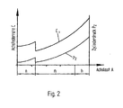
- the axle spring rate C and the cylinder pressure P z in relation to the axle load A are plotted on the front axle of a vehicle at a constant annular space pressure P R.
- the curve C shows the course of the axle spring rate C and the curve P the course of the cylinder pressure on the axle load A again.
- the axle load A is divided into a low n, middle m and high h load range.
- the low load range n is present when the vehicle is provided at its rear end with a load. This can for example be a plow in a farm tractor.
- the Vorderachsfederung is then relieved and is located in the low load range n.
- the front axle then has its highest axle load.
- the average load range m of the axle load is given when the vehicle is not loaded with devices either at the front or at the rear.
- the load limits are determined constructively and are matched to the tractor type with the selected attachments.
- the axle spring rate C depends on the selected gas preload and the volume of the hydraulic accumulator. If the axle spring rate C for the average load case m is tuned for high ride comfort, then this setting always has the consequence that the axle strikes in the low load range n without additional damper functions in unacceptable dimensions in the end stops. This can be avoided by hardening the axle spring rate in the low load range by annulus pressure increase.
- FIG. 2 and 3 the effect of annulus pressure increase in the curve of the axle spring rate C and the cylinder pressure P z is shown.
- the annulus pressure increase takes place only in the low load range n.
- Fig. 3 shows the diagram, although in the high load range h a Federratenverhärtung is required.
- the curves C 1 and C 2 are created . It was found that in both embodiments, a high level of ride comfort in the middle load range m is achieved.
- the idea underlying the invention is applicable in principle to all vehicles which are provided with hydropneumatic suspension devices and in which, depending on their workload, large axle load ratios occur.
- the pilot-operated pressure control valve is equipped with an external reaction pressure tap, which allows compensation of the internal flow resistances in small-shaped control blocks and thus causes the required accelerated pressure changes in the annulus.
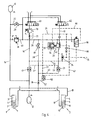
- FIG. 4 shows a circuit diagram for a tractor vehicle in which the suspension device has double-acting hydraulic cylinders whose pressure chambers can be connected to a load-sensing pump.
- the spring cylinders 1 and 2 are provided which are arranged between the unsprung and sprung masses, not shown.
- the spring cylinders 1 and 2 have the piston chambers 3 and 4, which are separated by the piston 5 and 6 of the annular spaces 7 and 8.
- the piston rods 9 and 10 are guided out of the spring cylinders 1 and 2 sealed to the outside.
- the two annular spaces 7 and 8 are connected to each other by the connecting line 11 and connected to the hydraulic accumulator 12.
- a second connecting line 13 connects the piston chambers 3 and 4.
- the connecting line 13 is connected via a line 14 to the hydraulic accumulator 15.
- In the line 14 opens the supply line 16, in which a pilot-operated check valve 17 is installed.
- the two check valves 17 and 21 open automatically in the direction of the piston chambers 3 and 4 or annular spaces 7 and 8. They can be unlocked via the control line 24 and the branching off lines 22 and 23 for a liquid flow in the opposite direction.
- the control line 24 is connected to the supply line 19.
- the pressure regulating valve 20 is inserted, with the pressure port P, discharge port T and the pressure port A for the regulated pressure.
- the drain line 26 is connected, which leads to a reservoir.
- the conduit 14 and the supply line 63 are connected to the drain line 26 via the drain lines 27 and 28, in which shut-off valves 29 and 30 are installed.
- the line 14 and the drain line 26 are connected via an intermediate line 60, in which a pressure relief valve 31 is inserted.
- the supply lines 16 and 19 are respectively connected to a solenoid valve 61 and 62, which are provided with the pressure ports P and the drain ports T.
- the valves 61 and 62 serve the level control function, which connect the supply lines 16 and 19 with a load-sensing pump or a reservoir depending on the level position of the vehicle.
- the lines 16 and 19 are connected to the drain port T. This is the neutral position.
- the serving as level control valves 61 and 62 are de-energized and are in their neutral position. Both supply lines 16 and 19 are connected to the drain T as shown in the circuit diagram. Due to the then missing control pressure, the check valves 17 and 21 can not be unlocked. They are closed and the piston chambers 3 and 4 as well as the annular spaces 7 and 8 are separated from any supply or discharge. The connections to the hydraulic accumulators 12 and 15 remain but so that the suspension of the vehicle is guaranteed. By the unpressurized State of the supply line 19, the control line 35 to the load-sensing pump is depressurized, since it can relieve the feed line 24 via the check valve 39. The load-sensing pump can then be operated in stand-by mode with comparatively low power requirement.
- the change in distance is tapped via a height sensor whose signal is converted into an electronically filtered control signals energizes the solenoid valves 61 and 62 and thus switches into Aufregelfunktion.
- the supply lines 16 and 19 are connected to the pump pressure P and via the line 19 and the pressure in the control line 24 is increased and the check valves 17, 21 and 50 unlocked.
- the shuttle valve 36 the pressures at the check valves 17 and 21 are fed, which feeds the highest pressure in the control line 35, so that the load-sensing pump can adjust to the required pressure level.
- Pressure fluid flows into the pressure line 14 and increases the pressure in the memory 15 to the required static pressure and then via line 13 into the cylinder chambers 3 and 4 until the level position is reached and the valves 61 and 62 switch back to their neutral position.
- the pressure in the annular spaces 7 and 8 and in the accumulator 12 is regulated by the 2-stage pressure control valve 20 to a predefined by the pilot valve 56 load-dependent pressure level.
- the Pilot valve 56 is acted upon via the control line 53 with the cylinder pressure from the pressure connection 16 and transmits the pressure control valve 20 via the control line 40 to be controlled pressure level in such a way that the pressure applied in the pilot valve 56 acts against a spring and pressure-dependent moves a piston, the in the middle and high pressure level in the load cases m and h, the control line 40 connects to the drain line 26 and thus switches without pressure and low line connects the line 40 to the pressure line 63 so that in the low load range n pressure oil flows to the control chamber 54 and the biasing piston 55th the control spring 41 in the control valve 20 biases higher and thus to increase the spring rate, a higher annular space pressure level is regulated.
- the control pressure for the control function of the pressure control valve 20 is externally tapped between the check valve 21 and an inserted before the connecting line 11 throttle 18, which is used to vote the control time in the branch 52 and is via the pilot operated check valve 50, the control line 51 to unlock with the Control line 24 is connected to the control line 42 connected.
- valve 62 is energized and switches to Abregelwolf in which it is ensured that the check valves 17 and 21 remain unlocked or unlocked. Pressure oil can then flow out via the unlocked check valve 17 via the line 16 and flow through the releasable check valve 21 pressure medium for adjusting the pressure levels until the level position is reached again.
- the pilot valve 56 it is possible to form the pilot valve 56 with double reversal, so even in the high Loading range h to achieve a harder spring rate, the control line 40 connected to the pressure line 19 and the pressure level is raised in the annulus.
- the pilot valve 56 may be formed as a 3-position valve.
- the pressure regulator 70 in cooperation with the throttle 71 in the pressure line 16, known from patent application DE 197 190 75, is used to control the Druckschzu- and outflow to the cylinder spring circuit, which results from the bond between the cylinder chambers 3 and 4 with the spring accumulator 15.
Landscapes
- Engineering & Computer Science (AREA)
- Mechanical Engineering (AREA)
- Vehicle Body Suspensions (AREA)
Description
- Die Erfindung betrifft ein Verfahren und eine Vorrichtung zur Steuerung des Federungsverhaltens bei Fahrzeugen mit hydropneumatischen Federungseinrichtungen und stark veränderbaren Achslastverhältnissen, insbesondere an Fahrzeugen bei denen abhängig vom Arbeitseinsatz die Vorderachse einem niedrigen, mittleren oder hohen statischem Belastungsbereich ausgesetzt ist und die Federungseinrichtung zwischen den ungefederten und gefederten Massen über doppelt wirkende Hydraulikzylinder verfügt, deren Druckleitungen mit einer Pumpe verbindbar sind, wobei ein Druckregelventil in die Druckleitung zu den Ringräumen eingefügt ist, das den Druck in den Ringräumen ständig auf einen vorgegebenen Druckwert abgleicht.
- Durch die DE 41 20 758 A1 ist eine hydropneumatische Federung für Kraftfahrzeuge mit großen Achslastspreizungen bekannt, bei der doppelt wirkende Hydraulikzylinder eingesetzt werden, deren Zylinderräume mit einem ersten Speicher und deren kolbenstangenseitige Ringräume mit einem zweiten Speicher verbunden sind, wobei ein Niveauregelventil die Höhenlage regelt und ein druckgesteuertes Ventil ein vorgegebenes Druckverhältnis zwischen den Drücken des ersten und des zweiten Speichers in Abhängigkeit von der Belastung der hydropneumatischen Stellglieder stetig regelt. Dabei wird das druckgesteuerte Ventil sowohl vom Druck in der Druckleitung zu den Zylinderräumen als auch vom Druck in der Druckleitung zu den Ringräumen betätigt. Es wird eine stetige Regelung in Abhängigkeit von der Belastung der hydropneumatischen Stellglieder erreicht. Der Ringraumdruck wird lastabhängig geregelt.
- Eine wirtschaftlichere, einfachere Ausführungsform ist in der DE 42 42 448 C1 enthalten, mit dem Vorteil, Load-Sensing-Pumpen einsetzen zu können. Nach Belastungsänderungen und anschließenden Auf- oder Abregelvorgängen werden statische Belastungsänderungen ausgeregelt. Es kommt ein Druckregelventil zum Einsatz, welches das Druckniveau im Ringraumfederkreis konstant hält. Bei mittleren Lasten wird die Federung jedoch hart und teilweise unkomfortabel.
- Eine Verbesserung der Verhältnisse hinsichtlich Komfort wird bei der Einrichtung nach DE 197 19 077 A1 dadurch erreicht, dass als Druckregelventil ein lastangepaßtes Zweistufenduckregelventil verwendet wird. Hierdurch ist es möglich, die Federung den Belastungsfällen besser anzupassen. Eine Änderung des Ringraumdrucks zwischen einem unteren und einem oberen Grenzwert ist lastabhängig möglich.
- Die DE 197 19 076 A1 zeigt eine Einrichtung, die eine Vergrößerung der Lastverhältnisse ohne erhöhte Beanspruchung der Bauteile zulässt und auch eine Verbesserung des Fahrkomforts im Sinne einer weicheren Federung erreicht. Die Regelfeder und die Positionierfeder des Druckregelventils sind so aufeinander abgestimmt, dass eine lastabhängige Ringraumdruckänderung erreicht wird, die eine Erhöhung der Federrate bei geringer Achslast bewirkt mit der Möglichkeit, die Federrate im mittleren Lastbereich zur Komfortverbesserung weicher zu gestalten. In Versuchen konnten die Funktionsvorteile nachgewiesen werden. Unbefriedigend sind jedoch bei dieser Einrichtungsart die für die Reproduzierbarkeit der Funktion geforderten eingeschränkten Fertigungstoleranzen und die ungünstige Baugröße. Für den permanenten Federungseinsatz erweist sich die Schnelligkeit der Druckanpassung als unzureichend.
- Der Erfindung liegt deshalb die Aufgabe zugrunde, eine Steuerung zu schaffen, bei der für eine wirtschaftliche Fertigung die Toleranzanforderungen entschärft sind, ein geringes Einbauvolumen ermöglicht wird und die geforderte schnelle Druckanpassung realisiert ist. Als niedriger Belastungsbereich der Vorderachse des Fahrzeugs wird der Bereich der gefederten Achslast verstanden, der eintritt, wenn das Fahrzeug an seinem rückwärtigen Ende mit einer Last, beispielsweise einem Pflug, versehen ist. Der hohe Belastungsbereich liegt vor, wenn frontseitig am Fahrzeug ein Ladegerät oder dergleichen angebracht ist. Der mittlere Belastungsbereich liegt bei einem unbelasteten Fahrzeug vor.
- Versuche haben gezeigt, dass eine komfortable Federungsauslegung im mittleren Belastungszustand bei Achslastreduzierung durch Heckanbaugeräte besonders bei weit ausragendem Schwerpunkt mit nicht vertretbarem Schwingen in die Endanschläge verbunden ist, sodass entweder eine zusätzliche Dämpferfunktion oder eine Federratenverhärtung einzubringen ist.
- Die Lösung der gestellten Aufgabe wird bei einem Verfahren beziehungsweise Vorrichtung der eingangs genannten Gattung erfindungsgemäß dadurch erreicht, dass in niedrigen Belastungsbereich an der Vorderachse der Druck in den Ringräumen der Federzylinder angehoben ist. Im mittleren Belastungsbereich ist der Druck im Ringraum zum Zwecke der Komfortsteigerung reduziert und im niedrigen Lastbereich verhärtet sich die Federrate durch Ringraumdruckerhöhung.
- In Verbindung mit der Speicherauslegung kann die Steuerung so abgestimmt werden, dass der Druck in den Ringräumen für den mittleren und hohen Belastungsfall konstant bleiben kann. Andererseits ist es aber auch möglich, den Ringraumdruck auch bei höherer Belastung der Vorderachse zu erhöhen.
- Die Anhebung des Ringraumdrucks kann auf unterschiedliche Werte eingestellt sein. Die Werte sind auf die Schleppergröße und den jeweiligen Belastungszuständen abzustimmen und sollte in Verbindung mit der Ringfläche des Federzylinders in der Größenordnung von 20 - 40 bar liegen.
- Die Speicherauslegung kann so abgestimmt werden, dass der Druckwert in den Ringräumen sowohl im mittleren als auch im hohen Lastbereich konstant bleiben kann
- Die Vorrichtung zur Durchführung des Verfahrens sieht die Verwendung eines Vorsteuerventils vor, welches vom Zulaufdruck zu den Zylinderräumen sowie vom Ablaufdruck gesteuert wird.
- Das mit einem Vorspannkolben ausgestattete Druckregelventil regelt einen unteren und einen oberen Druckwert. Welcher Druck zu regeln ist, wird von der Vorsteuerung bestimmt.
- Als Vorsteuerventil kann auch ein 3/2 - Wegeventil eingesetzt werden, dass über einen Drucksensor im Zylinderfederkreis elektrisch anzusteuern ist. Bei geforderter Verhärtung der Federrate im hohen Belastungsbereich ist eine weitere Umsteuerfunktion einzubringen.
- Die Vorteile der Erfindung werden bei einer weichen Anfangsgrundeinstellung in der Federauslegung erreicht, die einen guten Fahrkomfort im mittleren Belastungsbereich ergibt und einer härteren Abstimmung im niedrigen Belastungsbereich, wodurch die Problematik des Aufschwingens in die Endanschläge vermieden wird.
- Anhand der beiliegenden Zeichnung wird die Erfindung näher erläutert.
- Es zeigt:
- Fig. 1
- ein Federungsdiagramm, in dem die Achsfederrate und der Zylinderdruck in Bezug zur Achslast aufgetragen ist,
- Fig. 2
- das Federungsdiagramm mit erhöhtem Ringraumdruck im niedrigen Belastungsbereich,
- Fig. 3
- das Federungsdiagramm mit erhöhtem Ringraumdruck im niedrigen und hohen Belastungsbereich
- Fig. 4
- einen Schaltplan zur Durchführung der Ringraumdruckveränderung.
- In der Fig. 1 ist die Achsfederrate C und der Zylinderdruck Pz in Bezug zur Achslast A an der Vorderachse eines Fahrzeugs bei konstantem Ringraumdruck PR aufgetragen. Die Kurve C gibt den Verlauf der Achsfederrate C und die Kurve P den Verlauf des Zylinderdrucks über der Achslast A wieder. Dabei ist die Achslast A in einen niedrigen n, mittleren m und hohen h Belastungsbereich aufgeteilt. Der niedrige Belastungsbereich n liegt dann vor, wenn das Fahrzeug an seinem rückwärtigen Ende mit einer Last versehen ist. Das kann beispielsweise bei einem Ackerschlepper ein Pflug sein. Die Vorderachsfederung ist dann entlastet und befindet sich im niedrigen Belastungsbereich n. Eine hohe Achslast und damit ein hoher Belastungsbereich h der Vorderachsfederung liegt dann vor, wenn am Vorderteil des Schleppers ein Ladegerät oder dergleichen angebracht ist. Die Vorderachse hat dann ihre höchste Achslast. Der mittlere Belastungsbereich m der Achslast ist dann gegeben, wenn das Fahrzeug weder vorn noch hinten mit Geräten belastet ist. Die Belastungsgrenzen werden konstruktiv festgelegt und sind auf den Schleppertyp mit den gewählten Anbaugeräten abgestimmt.
- Bei bekannten hydropneumatischen Federungen mit konstantem Ringraumdruck werden für die Belastungsbereiche der niedrigen und hohen Achslasten die geforderten Federwege an den Federungseinrichtungen erreicht und damit ein guter Fahrkomfort erzielt. Im mittleren Achslastbereich treten jedoch überwiegend kurze Federwege auf, welche einen unbefriedigenden Fahrkomfort ergeben. Das Fahrverhalten der hydropneumatische Federung wirkt im mittleren Lastbereich unkomfortabel und hart.
- Die Achsfederrate C ist abhängig von der gewählten Gasvorspannung und dem Volumen des Hydrospeichers. Wird die Achsfederrate C für den mittleren Belastungsfall m auf hohem Fahrkomfort abgestimmt, so hat diese Einstellung immer zur Folge, dass die Achse im niedrigen Lastbereich n ohne zusätzliche Dämpferfunktionen in nicht zu vertretendem Maße in die Endanschläge anschlägt.
Dies lässt sich vermeiden, indem man die Achsfederrate im niedrigen Belastungsbereich durch Ringraumdruckerhöhung verhärtet. - In Fig. 2 und 3 ist die Wirkung der Ringraumdruckerhöhung im Kurvenverlauf der Achsfederrate C und dem Zylinderdruck Pz dargestellt. In Fig. 2 erfolgt die Ringraumdruckerhöhung nur im niedrigen Belastungsbereich n. Fig. 3 zeigt das Diagramm, wenn auch im hohen Belastungsbereich h eine Federratenverhärtung gefordert ist. Es entstehen die Kurven C1 und C2. Es zeigte sich, dass bei beiden Ausführungsformen ein hoher Fahrkomfort im mittleren Belastungsbereich m erzielt wird. Der der Erfindung zugrunde liegende Gedanke ist prinzipiell bei allen Fahrzeugen anwendbar, die mit hydropneumatischen Federungseinrichtungen versehen sind und bei denen in Abhängigkeit von ihrem Arbeitseinsatz große Achslastverhältnisse auftreten.
- Fahrversuche haben gezeigt, dass die Wirkung der Anpassung von Achsfederrate C an die jeweiligen Belastungszustände durch eine beschleunigte Ringraumdruckänderung optimiert werden kann. Dies gilt besonders für Federungssysteme ohne Federungsblockierung.
- Als erweitertes Erfindungsmerkmal ist aus diesem Grund das vorgesteuerte Druckregelventil mit einem externen Reaktionsdruckabgriff ausgestattet, der eine Kompensierung der internen Durchflusswiderstände bei klein gestalteten Steuerblöcken ermöglicht und somit die geforderten beschleunigten Druckänderungen im Ringraum bewirkt.
- In der Fig. 4 ist ein Schaltplan für ein Schlepperfahrzeug gezeigt, bei dem die Federungseinrichtung über doppelt wirkende Hydraulikzylinder verfügt, deren Druckräume mit einer Load-Sensing-Pumpe verbindbar sind.
- In dem gezeigten Schaltplan der Fig. 4 sind die Federzylinder 1 und 2 vorgesehen, die zwischen den nicht näher dargestellten ungefederten und gefederten Massen angeordnet sind. Die Federzylinder 1 und 2 besitzen die Kolbenräume 3 und 4, welche durch die Kolben 5 und 6 von den Ringräumen 7 und 8 getrennt sind. Die Kolbenstangen 9 und 10 sind aus den Federzylindern 1 und 2 abgedichtet nach außen geführt.
- Die beiden Ringräumen 7 und 8 sind durch die Verbindungsleitung 11 miteinander verbunden und an den Hydrospeicher 12 angeschlossen. Eine zweite Verbindungsleitung 13 verbindet die Kolbenräume 3 und 4. Die Verbindungsleitung 13 ist über eine Leitung 14 mit dem Hydrospeicher 15 verbunden. In die Leitung 14 mündet die Zuleitung 16, in die ein entsperrbares Rückschlagventil 17 eingebaut ist. In die Verbindungsleitung 11 mündet die Zuleitung 63, in welche die Drossel 18 eingefügt ist, und die ebenfalls ein entsperrbares Rückschlagventil 21 hat.
- Die beiden Rückschlagventile 17 und 21 öffnen selbsttätig in Richtung der Kolbenräume 3 und 4 beziehungsweise Ringräume 7 und 8. Sie können über die Steuerleitung 24 und die davon abzweigenden Leitungen 22 und 23 für einen Flüssigkeitsstrom in Gegenrichtung entsperrt werden. Die Steuerleitung 24 ist an die Zuleitung 19 angeschlossen. In die Zuleitung 19 ist das Druckregelventil 20 eingesetzt, mit dem Druckanschluss P, Ablaufanschluss T und dem Druckanschluss A für den geregelten Druck. An den Ablaufanschluss T des Druckregelventils 20 ist die Ablaufleitung 26 angeschlossen, die zu einem Vorratsbehälter führt. Die Leitung 14 und die Zuleitung 63 sind mit der Ablaufleitung 26 über die Entleerungsleitungen 27 und 28 verbunden, in die Absperrventile 29 und 30 eingebaut sind. Die Leitung 14 und die Ablaufleitung 26 sind über eine Zwischenleitung 60 verbunden, in die ein Druckbegrenzungsventil 31 eingesetzt ist. Die Zuleitungen 16 und 19 sind jeweils mit einem Magnet-Ventil 61 und 62 verbunden, die mit den Druckanschlüssen P und den Ablaufanschlüssen T versehen sind. Die Ventile 61 und 62 dienen der Niveauregelfunktion, die je nach Niveaulage des Fahrzeugs die Zuleitungen 16 und 19 mit einer Load-Sensing-Pumpe oder einem Vorratsbehälter verbinden. In der im Schaltplan gezeigten Schaltung sind die Leitungen 16 und 19 mit dem Ablaufanschluss T verbunden. Dieses ist die Neutralstellung.
- Die als Niveauregelventile dienenden Ventile 61 und 62 sind stromlos und befinden sich in ihrer Neutralstellung. Beide Zuleitungen 16 und 19 sind, wie in dem Schaltplan gezeigt, mit dem Ablauf T verbunden. Durch den dann fehlenden Steuerdruck können die Rückschlagventile 17 und 21 nicht entsperrt werden. Sie sind geschlossen und die Kolbenräume 3 und 4 sowie auch die Ringräume 7 und 8 sind von jeglicher Zu- oder Ableitung getrennt. Die Verbindungen zu den Hydrospeichern 12 und 15 bleiben aber bestehen, so dass die Federung des Fahrzeugs gewährleistet ist. Durch den drucklosen Zustand der Zuleitung 19 wird auch die Steuerleitung 35 zur Load-Sensing-Pumpe drucklos, da sie sich über das Rückschlagventil 39 in die Zuleitung 24 entlasten kann. Die Load-Sensing-Pumpe kann dann im Stand-by-Betrieb mit vergleichsweise geringem Leistungsbedarf betrieben werden.
- Sobald sich die statische Belastung erhöht, schieben die Kolbenstangen 9 und 10 die Kolben 5 und 6 nach oben, so dass sich die Kolbenräume 3 und 4 verkleinern und Drucköl unter Druckanstieg in den Speicher 15 gefördert wird, während sich die Ringräume 7 und 8 vergrößern und Drucköl unter Druckreduzierung aus dem Speicher 12 nachgefördert wird.
- Die Abstandsänderung wird über einen Höhensensor abgegriffen, dessen Signal in ein elektronisch gefiltertes Steuersignale umgewandelt die MagnetVentile 61 und 62 bestromt und somit in Aufregelfunktion schaltet. In dieser Schaltstellung werden die Zuleitungen 16 und 19 mit dem Pumpendruck P verbunden und über die Leitung 19 wird auch der Druck in der Steuerleitung 24 erhöht und die Rückschlagventile 17, 21 und 50 entsperrt.
- Dem Wechselventil 36 werden die Drücke an den Rückschlagventilen 17 und 21 zugeführt, das den höchsten Druck in die Steuerleitung 35 einspeist, damit die Load-Sensing-Pumpe auf das geforderte Druckniveau einregeln kann.
- Druckmittel strömt in die Druckleitung 14 ein und erhöht den Druck im Speicher 15 auf den geforderten statischen Druck und anschließend über die Leitung 13 in die Zylinderräume 3 und 4 bis die Niveaulage erreicht ist und die Ventile 61 und 62 in ihre Neutralstellung zurückschalten.
- Während des Regelvorgangs wird der Druck in den Ringräumen 7 und 8 und im Druckspeicher 12 durch das 2-Stufen-Druckregelventil 20 auf ein vom Vorsteuerventil 56 vorbestimmtes lastabhängiges Druckniveau eingeregelt. Das Vorsteuerventil 56 wird über die Steuerleitung 53 mit dem Zylinderdruck aus der Druckverbindung 16 beaufschlagt und übermittelt dem Druckregelventil 20 über die Steuerleitung 40 das zu regelnde Druckniveau in der Weise, dass der beaufschlagte Druck im Vorsteuerventil 56 gegen eine Feder wirkt und druckabhängig einen Kolben verschiebt, der im mittlerem und hohen Druckniveau bei den Belastungsfällen m und h die Steuerleitung 40 mit der Ablaufleitung 26 verbindet und somit drucklos schaltet und im niedrigem Niveau die Leitung 40 mit der Druckleitung 63 verbindet, sodass im niedrigem Lastbereich n Drucköl zum Steuerraum 54 fließt und der Vorspannkolben 55 die Regelfeder 41 im Regelventil 20 höher vorspannt und somit zur Erhöhung der Federrate ein höheres Ringraumdruckniveau geregelt wird.
- Der Steuerdruck für die Regelfunktion des Druckregelventils 20 wird extern zwischen dem Rückschlagventil 21 und einer vor der Verbindungsleitung 11 eingefügten Drossel 18, die zur Abstimmung der Regelzeit dient, im Abzweig 52 abgegriffen und ist über das entsperrbare Rückschlagventil 50, dessen Steuerleitung 51 zum Entsperren mit der Steuerleitung 24 angeschlossen ist, mit der Steuerleitung 42 verbunden.
- Bei einer Belastungsminderung an den Federzylindern 1 und 2 findet eine Vergrößerung der Kolbenräume 3 und 4 und eine Verkleinerung der Ringräume 7 und 8 statt. Das Ventil 62 wird bestromt und schaltet in Abregelstellung, in der sichergestellt ist, dass die Rückschlagventile 17 und 21 entsperrt bleiben bzw. entsperrt werden. Über das entsperrte Rückschlagventil 17 kann dann Drucköl über die Leitung 16 abströmen und durch das entsperrbare Rückschlagventil 21 Druckmittel zum Einregeln des Druckniveaus fließen, bis die Niveaulage wieder erreicht ist.
- In weiterer Ausgestaltung der Erfindung ist es möglich, das Vorsteuerventil 56 mit doppelter Umsteuerung auszubilden, sodass auch im hohen Belastungsbereich h zur Erzielung einer härteren Federrate die Steuerleitung 40 mit der Druckleitung 19 verbunden und das Druckniveau im Ringraum angehoben ist. Bei einer solchen Ausführungsform kann das Vorsteuerventil 56 als 3-Stellungsventil ausgebildet sein.
- Der Druckregler 70 im Zusammenwirken mit der Drossel 71 in der Druckleitung 16, bekannt durch Patentanmeldung DE 197 190 75, dient zur Regelung der Druckmittelzu- und abflussmenge zum Zylinderfederkreis, der sich aus dem Verbund zwischen den Zylinderräumen 3 und 4 mit dem Federspeicher 15 ergibt.
Claims (8)
- Vorrichtung zur Steuerung des Federungsverhaltens von Fahrzeugen mit stark veränderten Lastverhältnissen und einer hydropneumatischen Federungseinrichtung, bei der zwischen den gefederten und ungefederten Massen Federzylinder (1, 2) angeordnet sind, die die Last tragende Kolbenräume (3, 4) und die Kolbenstange abgedichtet umgebende druckbeaufschlagte Ringräume (7, 8) haben, wobei die Kolbenräume (3, 4) mit einem ersten Hydrospeicher (15) und die Ringräume (7, 8) mit einem zweiten Hydrospeicher (12) verbunden sind und ein Druckregelventil (20) vorhanden ist, das in die Druckleitung (19) zu den Ringräumen (7, 8) eingesetzt ist, dadurch gekennzeichnet, dass das Druckregelventil (20) durch ein Vorsteuerventil (56) gesteuert wird, das vom Zulaufdruck (Pz) zu den Kolbenräumen (3, 4) betätigt ist und das bei Unterschreiten eines vorgegebenen Zulaufdrucks (Pz) in der Zulaufleitung (16) zu den Kolbenräumen (3, 4) das Druckregelventil (20) auf eine höhere Regelstufe schaltet.
- Vorrichtung nach Anspruch 1 dadurch gekennzeichnet, dass das Vorsteuerventil (56), ausgebildet als Ventil mit doppelter Umsteuerung, das Druckregelventil (20) bei niedrigem und hohem Druckniveau vom Zulaufdruck (Pz) auf die höhere Regelstufe schaltet.
- Vorrichtung nach Anspruch 1 oder 2, dadurch gekennzeichnet, dass das Vorsteuerventil (56) ein 3/2-Wege-Magnet-Ventil ist, welches durch Drucksensor im Zulaufdruck (Pz) geschaltet wird.
- Vorrichtung nach einem der Ansprüche 1 bis 3 dadurch gekennzeichnet, dass die Steuerleitung (42) für die Regelfeder (41) des Druckregelventils (20) an die Zuleitung (63) zu den Ringräumen (7, 8) zwischen dem Rückschlagventil (21) und den Ringräumen (7, 8) angeschlossen ist.
- Vorrichtung nach einem der Ansprüche 1 bis 4 dadurch gekennzeichnet, dass die Steuerleitung (42) mit einem entsperrbaren Rückschlagventil (50) versehen ist.
- Vorrichtung nach einem der Ansprüche 1 bis 5 dadurch gekennzeichnet, dass zwischen dem Anschluss (52) der Steuerleitung (42) an die Zuleitung (60) und der Verbindungsleitung (11) der Ringräume (7, 8) eine Drossel (18) eingesetzt ist.
- Vorrichtung nach einem der Ansprüche 1 bis 6 dadurch gekennzeichnet, dass die Entsperrsteuerleitung (51) des Rückschlagventils (50) an die Steuerleitung (24) der Rückschlagventile (17, 21) der Zuleitungen (16, 19) angeschlossen ist.
- Vorrichtung nach einem der Ansprüche 1 bis 7 , dadurch gekennzeichnet, dass der Ringraumdruck (PR) in zwei Druckstufen mit einer Differenz bis zu 50 bar in Abhängigkeit vom Druck (Pz) in den Kolbenräumen (3, 4) geschaltet wird.
Applications Claiming Priority (2)
| Application Number | Priority Date | Filing Date | Title |
|---|---|---|---|
| DE10107631A DE10107631B4 (de) | 2001-02-15 | 2001-02-15 | Verfahren und Einrichtung zur Steuerung des Federungsverhaltens bei Fahrzeugen mit hydropneumatischen Federungseinrichtungen und stark veränderbaren Achslastverhältnissen |
| DE10107631 | 2001-02-15 |
Publications (3)
| Publication Number | Publication Date |
|---|---|
| EP1232883A2 EP1232883A2 (de) | 2002-08-21 |
| EP1232883A3 EP1232883A3 (de) | 2004-09-22 |
| EP1232883B1 true EP1232883B1 (de) | 2007-01-17 |
Family
ID=7674509
Family Applications (1)
| Application Number | Title | Priority Date | Filing Date |
|---|---|---|---|
| EP02002745A Expired - Lifetime EP1232883B1 (de) | 2001-02-15 | 2002-02-07 | Hydropneumatisches Fahrzeugaufhängungssystem |
Country Status (3)
| Country | Link |
|---|---|
| US (1) | US6786492B2 (de) |
| EP (1) | EP1232883B1 (de) |
| DE (2) | DE10107631B4 (de) |
Families Citing this family (19)
| Publication number | Priority date | Publication date | Assignee | Title |
|---|---|---|---|---|
| AUPR249901A0 (en) * | 2001-01-10 | 2001-02-01 | Kinetic Pty Limited | Vehicle suspension roll control system |
| US20060064071A1 (en) * | 2001-11-06 | 2006-03-23 | Possis Medical, Inc. | Gas inflation/evacuation system incorporating a reservoir and removably attached sealing system for a guidewire assembly having an occlusive device |
| DE10232769B4 (de) | 2002-07-18 | 2005-08-25 | Carl Freudenberg Kg | Hydropneumatische Achsfederung für Fahrzeuge für Fahrzeuge mit stark wechselden Achslasten |
| DE10257008A1 (de) * | 2002-12-06 | 2004-06-17 | Continental Aktiengesellschaft | Aus Feder und Dämpfer bestehende Federungsanordnung |
| DE10306756B4 (de) * | 2003-02-17 | 2007-01-04 | Carl Freudenberg Kg | Hydropneumatische Federungseinrichtung für Fahrzeuge |
| DE10337601A1 (de) * | 2003-08-16 | 2005-03-10 | Deere & Co | Hydropneumatische Federungseinrichtung |
| DE10338534B3 (de) * | 2003-08-19 | 2005-01-27 | Carl Freudenberg Kg | Vorrichtung zur Steuerung des Federungsverhaltens von Fahrzeugen mit wechselnden Achslasten |
| DE102005000889A1 (de) * | 2004-01-28 | 2005-08-18 | Luk Lamellen Und Kupplungsbau Beteiligungs Kg | Wankstabilisierungseinrichtung |
| DE102004058618A1 (de) * | 2004-12-04 | 2006-06-08 | Carl Freudenberg Kg | Anordnung zur Beeinflussung von Bewegungen eines Kraftfahrzeugs und Einrichtung zur Verwendung in einer Anordnung |
| US7615031B2 (en) * | 2005-09-01 | 2009-11-10 | Medrad, Inc. | Gas inflation/evacuation system incorporating a multiple element valved guidewire assembly having an occlusive device |
| DE102007050190A1 (de) | 2007-10-20 | 2009-04-23 | Daimler Ag | Gasfederspeicher |
| DE102008012704A1 (de) | 2008-03-05 | 2009-09-10 | Deere & Company, Moline | Hydraulische Federungsanordnung |
| DE102008046632A1 (de) | 2008-09-10 | 2009-05-07 | Daimler Ag | Gasfederspeicher |
| DE102009037536A1 (de) * | 2009-08-17 | 2011-03-24 | Benteler Automobiltechnik Gmbh | Vorrichtung zur aktiven Spureinstellung |
| DE102012106185B3 (de) * | 2012-07-10 | 2013-11-21 | Fsp Fluid Systems Partners Holding Ag | Steueranordnung für ein hydropneumatisches Federungssystem sowie hydropneumatisches Federungssystem mit einer solchen Steueranordnung |
| DE102012022030A1 (de) * | 2012-11-12 | 2014-05-15 | Deere & Company | Federungseinrichtung für eine beweglich gelagerte Fahrzeugachse |
| DE102013102069A1 (de) | 2013-03-01 | 2014-09-04 | Fsp Fluid Systems Partners Holding Ag | Proportional-Wegeventil sowie hydraulische Schaltung und hydropneumatisches Federungssystem mit einem derartigen Ventil |
| EP3330111B1 (de) * | 2016-12-02 | 2023-02-01 | Husco International, Inc. | Aufhängungssystem für einen geländewagen |
| US10029533B1 (en) | 2017-01-23 | 2018-07-24 | Caterpillar Underground Mining Pty Ltd | Vehicle suspension control system |
Family Cites Families (7)
| Publication number | Priority date | Publication date | Assignee | Title |
|---|---|---|---|---|
| WO1992000203A1 (de) * | 1990-06-28 | 1992-01-09 | Zahnradfabrik Friedrichshafen Ag | Hydropneumatische federung für fahrzeuge |
| DE4127801A1 (de) * | 1991-08-22 | 1993-02-25 | Hemscheidt Maschf Hermann | Hydropneumatisches federungssystem fuer eine fahrzeug-liftachse |
| DE4242448C1 (de) * | 1992-12-16 | 1994-03-31 | Integral Hydraulik Co | Hydro-pneumatische Federungseinrichtung |
| DE19719075B4 (de) * | 1997-05-06 | 2004-07-01 | Integral Accumulator Kg | Doppeltwirkendes Ventil zur Strombeeinflussung, insbesondere für hydro-pneumatische Federungseinrichtungen für Fahrzeuge mit großen Lastverhältnissen |
| DE19719076C2 (de) * | 1997-05-06 | 2000-05-04 | Integral Accumulator Kg | Hydropneumatische Federungseinrichtung für Fahrzeuge mit großen Lastverhältnissen |
| DE19719077C2 (de) * | 1997-05-06 | 2000-05-04 | Integral Accumulator Kg | Hydropneumatische Federung für Fahrzeuge |
| DE19748224B4 (de) * | 1997-10-31 | 2005-07-14 | Deere & Company, Moline | Hydropneumatische Achsfederung für angetriebene Fahrzeugachsen |
-
2001
- 2001-02-15 DE DE10107631A patent/DE10107631B4/de not_active Expired - Lifetime
-
2002
- 2002-02-07 EP EP02002745A patent/EP1232883B1/de not_active Expired - Lifetime
- 2002-02-07 DE DE50209257T patent/DE50209257D1/de not_active Expired - Lifetime
- 2002-02-13 US US10/075,794 patent/US6786492B2/en not_active Expired - Lifetime
Also Published As
| Publication number | Publication date |
|---|---|
| DE10107631A1 (de) | 2002-09-05 |
| US6786492B2 (en) | 2004-09-07 |
| DE10107631B4 (de) | 2007-04-05 |
| US20020171209A1 (en) | 2002-11-21 |
| DE50209257D1 (de) | 2007-03-08 |
| EP1232883A2 (de) | 2002-08-21 |
| EP1232883A3 (de) | 2004-09-22 |
Similar Documents
| Publication | Publication Date | Title |
|---|---|---|
| EP1232883B1 (de) | Hydropneumatisches Fahrzeugaufhängungssystem | |
| EP3233544B1 (de) | Kraftfahrzeug-fahrgestell | |
| EP0535116B1 (de) | Hydropneumatische federung für fahrzeuge | |
| EP1963118B1 (de) | Hydropneumatische achsfederung für fahrzeuge | |
| DE19703872A1 (de) | Hydraulischer Dämpfer | |
| WO2006021327A1 (de) | Federungsvorrichtung | |
| DE10232769B4 (de) | Hydropneumatische Achsfederung für Fahrzeuge für Fahrzeuge mit stark wechselden Achslasten | |
| DE68908846T2 (de) | Hydraulisches Fahrzeugaufhängungssystem. | |
| DE3881507T2 (de) | Vorrichtung für semi-aktive hydropneumatische Aufhängung und mit dieser Vorrichtung ausgestattetes Kraftfahrzeug. | |
| DE3824611A1 (de) | Feder-daempfer-system fuer fahrzeuge | |
| EP1238834A2 (de) | Aktives Fahrwerksystem eines Fahrzeugs | |
| DE102012019863A1 (de) | Fahrzeug | |
| DE10107644B4 (de) | Hydropneumatische Federung für Fahrzeuge mit stark wechselnden Achslasten | |
| DE19719076C2 (de) | Hydropneumatische Federungseinrichtung für Fahrzeuge mit großen Lastverhältnissen | |
| DE102014004337A1 (de) | Kommunalfahrzeug | |
| DE10306756B4 (de) | Hydropneumatische Federungseinrichtung für Fahrzeuge | |
| EP4096943B1 (de) | Hydropneumatisches federungssystem für fahrzeuge | |
| DE4221088C2 (de) | Aufhängungssystem für Fahrzeuge | |
| EP3398418A1 (de) | Hydrauliksystem einer land- oder bauwirtschaftlich nutzbaren arbeitsmaschine | |
| WO2017202485A1 (de) | Ventilvorrichtung | |
| DE19719075B4 (de) | Doppeltwirkendes Ventil zur Strombeeinflussung, insbesondere für hydro-pneumatische Federungseinrichtungen für Fahrzeuge mit großen Lastverhältnissen | |
| DE3901349C2 (de) | ||
| DE4118822C2 (de) | ||
| DE4026849C2 (de) | Ventilanordnung zum Erzeugen eines Steuerdrucks in einer hydraulischen Anlage | |
| DE19949152C2 (de) | Hydropneumatische Federung |
Legal Events
| Date | Code | Title | Description |
|---|---|---|---|
| PUAI | Public reference made under article 153(3) epc to a published international application that has entered the european phase |
Free format text: ORIGINAL CODE: 0009012 |
|
| AK | Designated contracting states |
Kind code of ref document: A2 Designated state(s): AT BE CH CY DE DK ES FI FR GB GR IE IT LI LU MC NL PT SE TR |
|
| AX | Request for extension of the european patent |
Free format text: AL;LT;LV;MK;RO;SI |
|
| PUAL | Search report despatched |
Free format text: ORIGINAL CODE: 0009013 |
|
| AK | Designated contracting states |
Kind code of ref document: A3 Designated state(s): AT BE CH CY DE DK ES FI FR GB GR IE IT LI LU MC NL PT SE TR |
|
| AX | Request for extension of the european patent |
Extension state: AL LT LV MK RO SI |
|
| 17P | Request for examination filed |
Effective date: 20040813 |
|
| AKX | Designation fees paid |
Designated state(s): AT BE CH CY DE DK ES FI FR GB GR IE IT LI LU MC NL PT SE TR |
|
| 17Q | First examination report despatched |
Effective date: 20050228 |
|
| GRAP | Despatch of communication of intention to grant a patent |
Free format text: ORIGINAL CODE: EPIDOSNIGR1 |
|
| GRAS | Grant fee paid |
Free format text: ORIGINAL CODE: EPIDOSNIGR3 |
|
| GRAA | (expected) grant |
Free format text: ORIGINAL CODE: 0009210 |
|
| AK | Designated contracting states |
Kind code of ref document: B1 Designated state(s): AT BE CH CY DE DK ES FI FR GB GR IE IT LI LU MC NL PT SE TR |
|
| PG25 | Lapsed in a contracting state [announced via postgrant information from national office to epo] |
Ref country code: NL Free format text: LAPSE BECAUSE OF FAILURE TO SUBMIT A TRANSLATION OF THE DESCRIPTION OR TO PAY THE FEE WITHIN THE PRESCRIBED TIME-LIMIT Effective date: 20070117 Ref country code: DK Free format text: LAPSE BECAUSE OF FAILURE TO SUBMIT A TRANSLATION OF THE DESCRIPTION OR TO PAY THE FEE WITHIN THE PRESCRIBED TIME-LIMIT Effective date: 20070117 Ref country code: IE Free format text: LAPSE BECAUSE OF FAILURE TO SUBMIT A TRANSLATION OF THE DESCRIPTION OR TO PAY THE FEE WITHIN THE PRESCRIBED TIME-LIMIT Effective date: 20070117 Ref country code: FI Free format text: LAPSE BECAUSE OF FAILURE TO SUBMIT A TRANSLATION OF THE DESCRIPTION OR TO PAY THE FEE WITHIN THE PRESCRIBED TIME-LIMIT Effective date: 20070117 |
|
| REG | Reference to a national code |
Ref country code: GB Ref legal event code: FG4D Free format text: NOT ENGLISH |
|
| REG | Reference to a national code |
Ref country code: CH Ref legal event code: EP |
|
| PG25 | Lapsed in a contracting state [announced via postgrant information from national office to epo] |
Ref country code: MC Free format text: LAPSE BECAUSE OF NON-PAYMENT OF DUE FEES Effective date: 20070228 Ref country code: CH Free format text: LAPSE BECAUSE OF NON-PAYMENT OF DUE FEES Effective date: 20070228 Ref country code: LI Free format text: LAPSE BECAUSE OF NON-PAYMENT OF DUE FEES Effective date: 20070228 |
|
| REG | Reference to a national code |
Ref country code: IE Ref legal event code: FG4D Free format text: LANGUAGE OF EP DOCUMENT: GERMAN |
|
| REF | Corresponds to: |
Ref document number: 50209257 Country of ref document: DE Date of ref document: 20070308 Kind code of ref document: P |
|
| PG25 | Lapsed in a contracting state [announced via postgrant information from national office to epo] |
Ref country code: SE Free format text: LAPSE BECAUSE OF FAILURE TO SUBMIT A TRANSLATION OF THE DESCRIPTION OR TO PAY THE FEE WITHIN THE PRESCRIBED TIME-LIMIT Effective date: 20070417 |
|
| PG25 | Lapsed in a contracting state [announced via postgrant information from national office to epo] |
Ref country code: ES Free format text: LAPSE BECAUSE OF FAILURE TO SUBMIT A TRANSLATION OF THE DESCRIPTION OR TO PAY THE FEE WITHIN THE PRESCRIBED TIME-LIMIT Effective date: 20070428 |
|
| PG25 | Lapsed in a contracting state [announced via postgrant information from national office to epo] |
Ref country code: PT Free format text: LAPSE BECAUSE OF FAILURE TO SUBMIT A TRANSLATION OF THE DESCRIPTION OR TO PAY THE FEE WITHIN THE PRESCRIBED TIME-LIMIT Effective date: 20070618 |
|
| NLV1 | Nl: lapsed or annulled due to failure to fulfill the requirements of art. 29p and 29m of the patents act | ||
| GBV | Gb: ep patent (uk) treated as always having been void in accordance with gb section 77(7)/1977 [no translation filed] |
Effective date: 20070117 |
|
| REG | Reference to a national code |
Ref country code: IE Ref legal event code: FD4D |
|
| REG | Reference to a national code |
Ref country code: CH Ref legal event code: PL |
|
| PLBE | No opposition filed within time limit |
Free format text: ORIGINAL CODE: 0009261 |
|
| STAA | Information on the status of an ep patent application or granted ep patent |
Free format text: STATUS: NO OPPOSITION FILED WITHIN TIME LIMIT |
|
| PG25 | Lapsed in a contracting state [announced via postgrant information from national office to epo] |
Ref country code: GB Free format text: LAPSE BECAUSE OF FAILURE TO SUBMIT A TRANSLATION OF THE DESCRIPTION OR TO PAY THE FEE WITHIN THE PRESCRIBED TIME-LIMIT Effective date: 20070117 |
|
| 26N | No opposition filed |
Effective date: 20071018 |
|
| BERE | Be: lapsed |
Owner name: CARL FREUDENBERG K.G. Effective date: 20070228 |
|
| PG25 | Lapsed in a contracting state [announced via postgrant information from national office to epo] |
Ref country code: BE Free format text: LAPSE BECAUSE OF NON-PAYMENT OF DUE FEES Effective date: 20070228 |
|
| PG25 | Lapsed in a contracting state [announced via postgrant information from national office to epo] |
Ref country code: FR Free format text: LAPSE BECAUSE OF FAILURE TO SUBMIT A TRANSLATION OF THE DESCRIPTION OR TO PAY THE FEE WITHIN THE PRESCRIBED TIME-LIMIT Effective date: 20070907 Ref country code: GR Free format text: LAPSE BECAUSE OF FAILURE TO SUBMIT A TRANSLATION OF THE DESCRIPTION OR TO PAY THE FEE WITHIN THE PRESCRIBED TIME-LIMIT Effective date: 20070418 |
|
| PG25 | Lapsed in a contracting state [announced via postgrant information from national office to epo] |
Ref country code: AT Free format text: LAPSE BECAUSE OF NON-PAYMENT OF DUE FEES Effective date: 20070207 |
|
| PG25 | Lapsed in a contracting state [announced via postgrant information from national office to epo] |
Ref country code: FR Free format text: LAPSE BECAUSE OF FAILURE TO SUBMIT A TRANSLATION OF THE DESCRIPTION OR TO PAY THE FEE WITHIN THE PRESCRIBED TIME-LIMIT Effective date: 20070117 |
|
| PG25 | Lapsed in a contracting state [announced via postgrant information from national office to epo] |
Ref country code: CY Free format text: LAPSE BECAUSE OF FAILURE TO SUBMIT A TRANSLATION OF THE DESCRIPTION OR TO PAY THE FEE WITHIN THE PRESCRIBED TIME-LIMIT Effective date: 20070117 |
|
| PG25 | Lapsed in a contracting state [announced via postgrant information from national office to epo] |
Ref country code: LU Free format text: LAPSE BECAUSE OF NON-PAYMENT OF DUE FEES Effective date: 20070207 |
|
| PG25 | Lapsed in a contracting state [announced via postgrant information from national office to epo] |
Ref country code: TR Free format text: LAPSE BECAUSE OF FAILURE TO SUBMIT A TRANSLATION OF THE DESCRIPTION OR TO PAY THE FEE WITHIN THE PRESCRIBED TIME-LIMIT Effective date: 20070117 |
|
| PGFP | Annual fee paid to national office [announced via postgrant information from national office to epo] |
Ref country code: IT Payment date: 20210226 Year of fee payment: 20 |
|
| PGFP | Annual fee paid to national office [announced via postgrant information from national office to epo] |
Ref country code: DE Payment date: 20210301 Year of fee payment: 20 |