EP1508389A2 - Method and apparatus for continuous casting of metals - Google Patents
Method and apparatus for continuous casting of metals Download PDFInfo
- Publication number
- EP1508389A2 EP1508389A2 EP04025797A EP04025797A EP1508389A2 EP 1508389 A2 EP1508389 A2 EP 1508389A2 EP 04025797 A EP04025797 A EP 04025797A EP 04025797 A EP04025797 A EP 04025797A EP 1508389 A2 EP1508389 A2 EP 1508389A2
- Authority
- EP
- European Patent Office
- Prior art keywords
- magnetic field
- mold
- molten metal
- static magnetic
- flow
- Prior art date
- Legal status (The legal status is an assumption and is not a legal conclusion. Google has not performed a legal analysis and makes no representation as to the accuracy of the status listed.)
- Withdrawn
Links
- 239000002184 metal Substances 0.000 title claims abstract description 67
- 229910052751 metal Inorganic materials 0.000 title claims abstract description 67
- 238000000034 method Methods 0.000 title claims abstract description 29
- 238000009749 continuous casting Methods 0.000 title claims abstract description 16
- 150000002739 metals Chemical class 0.000 title claims abstract description 7
- 230000003068 static effect Effects 0.000 claims abstract description 34
- 238000005266 casting Methods 0.000 claims abstract description 25
- 238000007654 immersion Methods 0.000 claims description 11
- XEEYBQQBJWHFJM-UHFFFAOYSA-N Iron Chemical group [Fe] XEEYBQQBJWHFJM-UHFFFAOYSA-N 0.000 claims description 7
- 230000004907 flux Effects 0.000 abstract description 34
- 238000003887 surface segregation Methods 0.000 abstract description 16
- 229910052755 nonmetal Inorganic materials 0.000 abstract description 4
- 238000006263 metalation reaction Methods 0.000 abstract description 2
- 230000007547 defect Effects 0.000 description 22
- 229910000831 Steel Inorganic materials 0.000 description 20
- 239000010959 steel Substances 0.000 description 20
- 238000003754 machining Methods 0.000 description 7
- 230000008569 process Effects 0.000 description 6
- 230000000052 comparative effect Effects 0.000 description 5
- 230000000694 effects Effects 0.000 description 5
- 238000002474 experimental method Methods 0.000 description 5
- 230000005499 meniscus Effects 0.000 description 5
- 229910000655 Killed steel Inorganic materials 0.000 description 4
- 238000013019 agitation Methods 0.000 description 4
- 238000007796 conventional method Methods 0.000 description 4
- 239000000843 powder Substances 0.000 description 4
- 238000005204 segregation Methods 0.000 description 4
- 238000007711 solidification Methods 0.000 description 3
- 229910052720 vanadium Inorganic materials 0.000 description 3
- 238000005406 washing Methods 0.000 description 3
- RYGMFSIKBFXOCR-UHFFFAOYSA-N Copper Chemical compound [Cu] RYGMFSIKBFXOCR-UHFFFAOYSA-N 0.000 description 2
- 230000003213 activating effect Effects 0.000 description 2
- 230000002238 attenuated effect Effects 0.000 description 2
- 229910052802 copper Inorganic materials 0.000 description 2
- 239000010949 copper Substances 0.000 description 2
- 238000005259 measurement Methods 0.000 description 2
- 238000012986 modification Methods 0.000 description 2
- 230000004048 modification Effects 0.000 description 2
- 238000006467 substitution reaction Methods 0.000 description 2
- 229910052770 Uranium Inorganic materials 0.000 description 1
- 238000005452 bending Methods 0.000 description 1
- 230000008859 change Effects 0.000 description 1
- 238000005097 cold rolling Methods 0.000 description 1
- 230000000295 complement effect Effects 0.000 description 1
- 230000002950 deficient Effects 0.000 description 1
- 230000002500 effect on skin Effects 0.000 description 1
- 238000005530 etching Methods 0.000 description 1
- 238000011156 evaluation Methods 0.000 description 1
- 229910052742 iron Inorganic materials 0.000 description 1
- 239000000463 material Substances 0.000 description 1
- 230000007246 mechanism Effects 0.000 description 1
- 239000000203 mixture Substances 0.000 description 1
- 150000002843 nonmetals Chemical class 0.000 description 1
- 238000005457 optimization Methods 0.000 description 1
- 238000003825 pressing Methods 0.000 description 1
- 230000008023 solidification Effects 0.000 description 1
- 239000000126 substance Substances 0.000 description 1
- 229910052721 tungsten Inorganic materials 0.000 description 1
- 230000000007 visual effect Effects 0.000 description 1
- 238000004804 winding Methods 0.000 description 1
Images




Classifications
-
- B—PERFORMING OPERATIONS; TRANSPORTING
- B22—CASTING; POWDER METALLURGY
- B22D—CASTING OF METALS; CASTING OF OTHER SUBSTANCES BY THE SAME PROCESSES OR DEVICES
- B22D11/00—Continuous casting of metals, i.e. casting in indefinite lengths
-
- B—PERFORMING OPERATIONS; TRANSPORTING
- B22—CASTING; POWDER METALLURGY
- B22D—CASTING OF METALS; CASTING OF OTHER SUBSTANCES BY THE SAME PROCESSES OR DEVICES
- B22D11/00—Continuous casting of metals, i.e. casting in indefinite lengths
- B22D11/10—Supplying or treating molten metal
- B22D11/11—Treating the molten metal
- B22D11/114—Treating the molten metal by using agitating or vibrating means
- B22D11/115—Treating the molten metal by using agitating or vibrating means by using magnetic fields
Definitions
- the present invention relates to a continuous casting method and apparatus for effecting flow control of molten steel using a magnetic field during continuous casting of steel.
- an immersion nozzle In continuous casting, an immersion nozzle is often used to pour a molten metal into a casting mold. If the flow speed of the surface molten metal is too high at that time, mold flux on the surface of the molten metal is entrained (or involved) into a body of the molten metal, and if the flow speed of the surface molten metal is too low, the molten metal stagnates and segregates there, thus finally giving rise to surface segregation.
- a method of applying a static magnetic field and/or a moving magnetic field (AC moving magnetic field) to the molten metal in the mold for controlling the flow speed of the molten metal for controlling the flow speed of the molten metal.
- the known method has problems as follows.
- a static magnetic field is applied to brake a flow of the molten metal (for electromagnetic braking)
- segregation tends to occur readily, particularly in a position where the molten metal stagnates.
- a moving magnetic field is applied to agitate the molten metal (for electromagnetic agitation)
- entrainment of the mold flux (flux entrainment) tends to occur readily in a position where the flow speed of the molten metal is high.
- Japanese Unexamined Patent Application Publication No. 9-182941 discloses a method of periodically reversing the direction, in which a molten metal is agitated by a moving magnetic field, to prevent inclusions from diffusing downward from an agitation area.
- Japanese Unexamined Patent Application Publication No. 8-187563 discloses a method of preventing a breakout by changing the magnitude of a high-frequency electromagnetic force depending on vibration of a casting mold.
- Japanese Unexamined Patent Application Publication No. 8-155605 discloses a method of applying a horizontally moving magnetic field at frequency of 10 - 1000 Hz through conductive layers, each of which has low electrical conductivity and is formed to extend continuously in the direction of transverse width of a casting mold, and imposing a pinching force on a molten metal so that a contact pressure between the casting mold and the molten metal is reduced.
- a continuous casting method for casting a metal while applying a static magnetic field in the direction of thickness of a cast slab comprising the step of intermittently applying the static magnetic field.
- intermittent application means a process of alternately repeating application (on) of the static magnetic field and no application (off) of the static magnetic field.
- the AC magnetic field when continuous casting is performed by applying a DC magnetic field and an AC magnetic field in superimposed fashion in the direction of transverse width of a casting mold at positions above and below an ejection port of an immersion nozzle immersed in a molten metal in the mold, the AC magnetic field may be moved in a longitudinally symmetrical relation from both ends to the center of the mold in the direction of longitudinal width thereof.
- the above method can be implemented by a continuous casting apparatus for molten metals, the apparatus comprising a coil for producing an AC magnetic field moving in a longitudinally symmetrical relation from both ends to the center of the mold in the direction of longitudinal width thereof, and a coil for producing a DC magnetic field, both the coils being wound over each of common iron cores, the iron cores being arranged on both sides of the mold in the direction of transverse width thereof such that a direction of the magnetic fields produced by the coils is aligned with the direction of transverse width of the mold.
- casting is performed while applying a static magnetic field in the direction of longitudinal width of a casting mold to prevent the flux entrainment, but the static magnetic field is intermittently applied by turning on/off application of the magnetic field in an alternate manner, as shown in Fig. 2, rather than continuously applying a constant magnetic field in steady fashion (holding an on-state).
- a static magnetic field in the direction of longitudinal width of a casting mold to prevent the flux entrainment
- the static magnetic field is intermittently applied by turning on/off application of the magnetic field in an alternate manner, as shown in Fig. 2, rather than continuously applying a constant magnetic field in steady fashion (holding an on-state).
- t1 an on-time
- t2 an off-time
- the vector of an eddy current generated in an acting area of the magnetic field is greatly changed upon the on/of f switching, and a micro flow of a molten metal is produced in the acting area.
- the produced micro flow contributes to preventing semi-solidification of the molten metal near the surface thereof, and to almost completely eliminate the occurrence of surface segregation.
- both the flux entrainment and the surface segregation can be prevented, but the degree of the resulting effect depends on how the on-time t1 and the off-time t0 are set. More specifically, if t0 and t1 are too short, the applied magnetic field becomes close to a state resulting from application of an AC magnetic field, whereby the flow speed of the surface molten metal cannot be reduced satisfactorily and the flux entrainment is caused. If t0 is too long, the flow speed of the molten metal is increased and the effect of effecting the flux entrainment becomes insufficient. Also, if t1 is too long, the flow speed of the molten metal is so reduced that the surface segregation is noticeable.
- the advantages of this aspect of the present invention are obtained most remarkably when the static magnetic field is applied to the surface of the molten metal. It is therefore preferable to apply the static magnetic field to the surface of the molten metal. Even when the static magnetic field is applied to the interior of the molten metal, however, similar advantages can also be obtained so long as an influence of the static magnetic field is transmitted to the surface flow of the molten metal through an internal flow of the molten metal.
- casting of a high-quality metal slab can be achieved which is free from the surface segregation and suffers from the flux entrainment at a less degree.
- An AC magnetic field may be moved in a longitudinally symmetrical relation from both ends toward the center of a casting mold in the direction of longitudinal width thereof.
- an AC and DC superimposed magnetic field is applied to a molten metal at two positions (in two steps) spaced in the casting direction (direction of height of a casting mold) so as to spread in the direction of thickness of a cast slab (direction of short side (transverse width) of the mold).
- this other aspect of the present invention differs from the above-described aspect in producing a moving AC magnetic field and from the conventional method in direction of movement of an AC magnetic field. More specifically, in the conventional method, the AC magnetic field is moved from one end toward the other end of the mold in the direction of width of the cast slab (direction of long side (longitudinal width) of the mold).
- the AC magnetic field is moved in a longitudinally symmetrical relation from both ends toward the center of the mold in the direction of longitudinal width thereof.
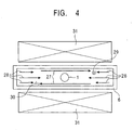
- a horizontal circulating flow 27 along the periphery of the casting mold 6 is generated, as shown in Fig. 4, even when a DC magnetic field is superimposed on the AC magnetic field. Therefore, the occurrence of a vortex and stagnation due to collision between the circulating flow and an ejected-and-reversed surfacing flow cannot be prevented, which makes it difficult to prevent entrainment of flux powder at the surface of the molten metal and capture of bubbles and inclusions by a widthwise surface of a solidified shell.
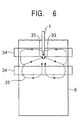
- the AC magnetic field develops due to the skin effect an agitating force prevailing over a braking force developed by the DC magnetic field, thereby activating the flow in such an area and preventing the capture of bubbles and inclusions into the cast slab.
- the agitating force developed by the AC magnetic field is attenuated and the braking force developed by the DC magnetic field acts primarily.
- flows upward and downward flows branched from the ejected flow
- flows in a central area are damped, whereby disorder of the flow speed of the surface molten metal is held down and entrainment of flux powder is avoided.
- the flow speed of the downward flow is reduced and large-sized inclusions are prevented from intruding into a deeper area.
- the AC magnetic field preferably has frequency of 0.1 - 10 Hz. If the frequency is lower than 0.1 Hz, it is difficult to produce a molten metal flow enough to develop the Washing effect along the widthwise surface of the solidified shell. Conversely, if the frequency exceeds 10 Hz, the applied AC magnetic field is attenuated by mold copper plates, and hence it is also difficult to produce a molten metal flow enough to develop the Washing effect along the widthwise surface of the solidified shell.
- Figs. 7A and 7B show one example of an apparatus suitable for implementing the above-described method according to this aspect of the present invention
- Fig. 7A is a schematic sectional plan view
- Fig. 7B is a schematic sectional side view.
- a pair of electromagnets 32 for both AC and DC currents are arranged in an opposing relation on both sides of a casting mold 6 in the direction of transverse width thereof with an immersion nozzle 1 placed within the mold 6.
- An iron core (yoke) 8 of each AC/DC electromagnet 32 has magnetic poles spaced in the vertical directions.
- Upper and lower magnetic poles (an upper pole and a lower pole) are positioned respectively above and below an ej ection port of the immersion nozzle 1, and the upper and lower poles of both the AC/DC electromagnets 32 are aligned with each other in the direction of thickness of the cast slab.
- DC coils 18 are wound such that the opposing magnetic poles on both the sides of the mold 6 have polarities complementary to each other (i.e., if the magnetic pole on one side is N, the magnetic pole on the other side is S).
- a front end portion of each magnetic pole is divided into plural pairs (three in the illustrated apparatus) of branches.
- An AC coil 19 is wound over each branch, and the DC coil 18 is wound over a root in common to all the branches.
- a three-phase AC current is supplied to the AC coils 19. Assuming different phases of the three-phase AC current to be U, V and W phases, respectively, the W phase is supplied to two first AC coils 19 counting to the left and right from the center of mold in the direction of longitudinal width thereof, the V phase is supplied to two second AC coils 19, and the U phase is supplied to two third AC coils 19.
- the AC magnetic field produced by the multi-phase AC current can be moved in directions indicated by arrows 21, i . e . , directions from the both ends toward the center of the mold in the direction of longitudinal width thereof in a longitudinally symmetrical relation.
- the number of branches formed in the front end portion of each magnetic pole is preferably set depending on the width of the cast slab.
- the AC/DC electromagnets are preferably disposed so as to cover the entire width of the cast slab as illustrated.
- a strand of low carbon-and-Al killed steel being 1500 mm wide and 220 mm thick was cast by pouring the molten killed steel at a casting rate of 1.8 m/min and 2.5 m/min and an immersion nozzle ejection angle of 15° downward from the horizontal with a continuous casting machine of the vertical bending type.
- experiments were conducted by employing the same apparatus as shown in Fig. 7, and applying magnetic fields to a portion of the strand corresponding to the mold position under various conditions of applying the magnetic fields as listed in Table 6.
- a cast slab was subjected to measurement of a surface defect index determined by inspecting surface defects of a steel plate after being rolled, and a machining crack index determined by inspecting inclusion-based machining cracks caused during pressing of a steel plate.
- the surface defect index and the machining crack index are each defined as an index that takes a value of 1.0 when electromagnetic flow control is not carried out.
- each magnetic pole represented by the moving type B different phases of the three-phase AC supplied to the AC coils were arranged in a longitudinally symmetrical relation in the direction of longitudinal width of the mold as shown Fig. 1 so as to produce the flows in the molten steel moving from both the ends to the center of the mold in the direction of longitudinal width thereof in accordance with this aspect of the present invention.
- a thus-produced AC magnetic field (referred to as a type-B AC magnetic field) was moved in a longitudinally symmetrical relation from both the ends to the center of the mold in the direction of longitudinal width thereof.
- the intensity of the AC magnetic field is represented by an effective value of the magnetic flux density at an inner surface position of a mold copper plate when the AC magnetic field is solely applied
- the intensity of the DC magnetic field is represented by a value of the magnetic flux density at the center of the cast slab in the direction of thickness thereof when the DC magnetic field is solely applied.
- the magnetic pole in which the intensities of both the AC and DC magnetic fields are not 0 T, represents a pole to which the AC and DC superimposed magnetic field was applied.
- the conditions 1 to 5 represent Comparative Examples departing from the scope of the present invention, and the condition 6 represents Example falling within the scope of the present invention.
- Measurement results of the surface defect index and the machining crack index are also listed in Table 6. Note that the measured result is expressed by an average of two values measured for two different casting rate conditions.
- the type-A AC magnetic field and the DC magnetic field were applied solely or in superimposed fashion.
- supply of the molten steel heat was insufficient and a claw-like structure grew in an initially solidified portion.
- the claw-like structure catches flux powder and increased the surface defect index.
- growth of the claw-like structure could be held down, but the electromagnetic braking force was so small that inclusions intruded into a deeper area of a not-yet-solidified molten steel bath within the cast slab.
- Example of Table 6 employed the condition 6 in which the type-B AC magnetic field was applied (frequency was changed from 2 Hz to 5 Hz for optimization) instead of the type-A AC magnetic field employed in the condition 5.
- the Washing effect along the widthwise surface of the solidified shell was enhanced, and the electromagnetic braking force was caused to act upon a central portion of the cast slab in the direction of thickness thereof to reduce the flow speeds of the molten steel flows (upward and downward flows branched from the ejected flow) and to promote creation of laminar flows. Further, generation of the circulating flow in the meniscus area could be held down, and the vortex and stagnation were avoided from being produced there. As a result, both the surface defect index and the machining crack index could be reduced down to 0.05 that was not obtained with the
- the upward and downward flows branched from the ejected flow can be damped, and at the same time the molten steel flow along the widthwise surface of the solidified shell can be activated.
- a vortex and stagnation can be prevented from being caused upon collision between the circulating flow created by electromagnetic agitation and the ejected-and-reversed surfacing flow in the meniscus area. Therefore, a cast slab having even higher quality can be produced.
- a metal slab can be cast which is much less susceptible to bubbles and non-metal inclusions captured in the cast slab, surface segregation, as well as surface defects and internal inclusions attributable to mold flux. Hence, a high-quality metal product can be produced.
Landscapes
- Engineering & Computer Science (AREA)
- Mechanical Engineering (AREA)
- Continuous Casting (AREA)
Abstract
Description
Surface Segregation: After grinding the cast slab, the slab was subjected to etching and the number of segregates per 1 m2 was counted by visual observation.
Flux-based Surface Defects: Surface defects in a coil obtained after cold rolling of the cast slab were visually observed, and after picking a defective sample, the number of defects caused by entrainment of mold flux was counted by analyzing the defects. Inclusion Amount: Inclusions were extracted by the slime extracting process from a portion of the cast slab at a position corresponding to a 1/4 thickness thereof, and the weight of the extracted inclusions was measured.


Claims (6)
- A method for continuous casting of metals, comprising intermittently applying a static magnetic field in a thickness direction of a cast slab.
- The method according to Claim 1 , wherein said static magnetic field is intermittently applied under setting of an on-time t1 = 0.10 to 30 seconds and an off-time t0 = 0.10 to 30 seconds.
- The method according to Claim 1, wherein said static magnetic field is applied to a surface of a molten metal.
- The method according to Claim 2 , wherein said static magnetic field is applied to a surface of a molten metal.
- A method for continuous casting of metals, comprising the steps of:applying a DC magnetic field and an AC magnetic field in superimposed fashion along a transverse width of a casting mold at positions above and below an ejection port of an immersion nozzle; andmoving said AC magnetic field in a longitudinally symmetrical relation from opposite ends to a center of said mold along a longitudinal width thereof.
- An apparatus for continuous casting of molten metals, the molten metal being continuously cast using a casting mold, said apparatus comprising:means for applying magnetic fields at positions above and below an ejection port of an immersion nozzle; anda first coil for producing an AC magnetic field moving in a longitudinally symmetrical relation from opposite ends to a center of said mold along a longitudinal width thereof, and a second coil for producing a DC magnetic field, both said first and second coils being wound over each of common iron cores,said iron cores being arranged on opposite sides of said mold along a transverse width thereof such that a direction of the magnetic fields produced by said coils is aligned with the transverse width of said mold.
Applications Claiming Priority (5)
| Application Number | Priority Date | Filing Date | Title |
|---|---|---|---|
| JP2000207973A JP3520841B2 (en) | 2000-07-10 | 2000-07-10 | Metal continuous casting method |
| JP2000207972 | 2000-07-10 | ||
| JP2000207973 | 2000-07-10 | ||
| JP2000207972A JP4427875B2 (en) | 2000-07-10 | 2000-07-10 | Metal continuous casting method |
| EP00125142A EP1172158B1 (en) | 2000-07-10 | 2000-11-17 | Method and apparatus for continuous casting of metals |
Related Parent Applications (1)
| Application Number | Title | Priority Date | Filing Date |
|---|---|---|---|
| EP00125142A Division EP1172158B1 (en) | 2000-07-10 | 2000-11-17 | Method and apparatus for continuous casting of metals |
Publications (2)
| Publication Number | Publication Date |
|---|---|
| EP1508389A2 true EP1508389A2 (en) | 2005-02-23 |
| EP1508389A3 EP1508389A3 (en) | 2005-05-04 |
Family
ID=26595674
Family Applications (2)
| Application Number | Title | Priority Date | Filing Date |
|---|---|---|---|
| EP00125142A Expired - Lifetime EP1172158B1 (en) | 2000-07-10 | 2000-11-17 | Method and apparatus for continuous casting of metals |
| EP04025797A Withdrawn EP1508389A3 (en) | 2000-07-10 | 2000-11-17 | Method and apparatus for continuous casting of metals |
Family Applications Before (1)
| Application Number | Title | Priority Date | Filing Date |
|---|---|---|---|
| EP00125142A Expired - Lifetime EP1172158B1 (en) | 2000-07-10 | 2000-11-17 | Method and apparatus for continuous casting of metals |
Country Status (7)
| Country | Link |
|---|---|
| US (2) | US6712124B1 (en) |
| EP (2) | EP1172158B1 (en) |
| KR (1) | KR100740814B1 (en) |
| CN (1) | CN1258414C (en) |
| CA (2) | CA2325808C (en) |
| DE (1) | DE60017885T2 (en) |
| TW (1) | TW555604B (en) |
Families Citing this family (22)
| Publication number | Priority date | Publication date | Assignee | Title |
|---|---|---|---|---|
| KR100592533B1 (en) * | 2002-01-07 | 2006-06-23 | 조순형 | Continuous foamed metal manufacturing method and apparatus |
| EP1623777B1 (en) * | 2003-04-11 | 2007-04-18 | JFE Steel Corporation | Continuous casting method for steel |
| JP4348988B2 (en) * | 2003-04-11 | 2009-10-21 | Jfeスチール株式会社 | Steel continuous casting method |
| JP4054319B2 (en) * | 2004-03-29 | 2008-02-27 | オリンパス株式会社 | Power supply |
| CN100422363C (en) * | 2006-10-26 | 2008-10-01 | 中南大学 | Foaming device for preparing foamed aluminum or foamed aluminum alloy by melt foaming method |
| US20080179036A1 (en) * | 2007-01-26 | 2008-07-31 | Nucor Corporation | Continuous steel slab caster and methods using same |
| US8020605B2 (en) * | 2007-01-26 | 2011-09-20 | Nucor Corporation | Continuous steel slab caster and methods using same |
| PH12012501730A1 (en) * | 2010-03-10 | 2014-09-24 | Jfe Steel Corp | Continuous casting method for steel and method for manufacturing steel sheet |
| KR101745020B1 (en) * | 2011-12-13 | 2017-06-21 | 현대자동차주식회사 | Magneto-rheological Elastomer for Preparing to Improve Magneto-rheological Effect |
| EP2794149B1 (en) | 2011-12-22 | 2015-06-24 | Abb Ab | Arrangement and method for flow control of molten metal in a continuous casting process |
| GB201305822D0 (en) * | 2013-03-28 | 2013-05-15 | Pavlov Evgeny | Improvements in and relating to apparatus and methods |
| US10563275B2 (en) * | 2014-10-16 | 2020-02-18 | Glassy Metal, Llc | Method and apparatus for supercooling of metal/alloy melts and for the formation of amorphous metals therefrom |
| KR20170054544A (en) * | 2014-11-20 | 2017-05-17 | 에이비비 슈바이쯔 아게 | Electromagnetic brake system and method of controllong molten metal flow in a metal-making process |
| AT519029B1 (en) * | 2016-08-31 | 2019-10-15 | Primetals Technologies Austria GmbH | Stirring coil arrangement in a continuous casting plant |
| CN108500228B (en) * | 2017-02-27 | 2020-09-25 | 宝山钢铁股份有限公司 | Flow field control method for slab continuous casting crystallizer |
| RU2019141258A (en) * | 2017-05-24 | 2021-06-24 | Пиротек, Инк. | Modified method of casting metals in an electromagnetic field |
| EP3415251A1 (en) * | 2017-06-16 | 2018-12-19 | ABB Schweiz AG | Electromagnetic brake system and method of controlling an electromagnetic brake system |
| KR102310701B1 (en) * | 2019-12-27 | 2021-10-08 | 주식회사 포스코 | Casting apparatus and casting method |
| CN112388918B (en) * | 2020-10-22 | 2022-11-25 | 天鑫精工科技(威海)有限公司 | Short-period defoaming mold based on magnetostrictive effect |
| CN115106514A (en) * | 2021-03-18 | 2022-09-27 | 宝山钢铁股份有限公司 | Method for inhibiting ladle spinning and slag discharging in non-direct contact mode and ladle |
| CZ309098B6 (en) * | 2021-05-28 | 2022-01-26 | Technická univerzita v Liberci | Method and device for preparation of metal foam |
| CN115194107B (en) * | 2022-07-13 | 2023-05-16 | 沈阳工程学院 | Multi-stage independent adjustable composite magnetic field device and method for controlling metal liquid flow |
Family Cites Families (27)
| Publication number | Priority date | Publication date | Assignee | Title |
|---|---|---|---|---|
| JPS5326210B2 (en) * | 1974-03-23 | 1978-08-01 | ||
| DE3517733A1 (en) * | 1985-05-17 | 1986-11-20 | Theodor Prof. Dr.-Ing. 8022 Grünwald Rummel | Method and apparatus for the continuous casting of, in particular, heavy metals, by means of magnetic fields which shape the cross-section of the strand |
| US4905756A (en) * | 1988-10-18 | 1990-03-06 | United States Department Of Energy | Electromagnetic confinement and movement of thin sheets of molten metal |
| JP2917223B2 (en) | 1989-04-14 | 1999-07-12 | 新日本製鐵株式会社 | Metal solidification structure refinement casting method |
| JPH084885B2 (en) | 1990-08-21 | 1996-01-24 | 株式会社神戸製鋼所 | In-mold electromagnetic stirring method for continuous casting of slabs |
| JPH05154623A (en) | 1991-12-04 | 1993-06-22 | Nippon Steel Corp | Molten Steel Flow Control Method in Mold |
| JP3076667B2 (en) | 1992-04-23 | 2000-08-14 | 新日本製鐵株式会社 | Steel continuous casting method |
| JP3236422B2 (en) | 1992-10-16 | 2001-12-10 | 川崎製鉄株式会社 | Continuous casting method of steel using magnetic field |
| JP3067916B2 (en) | 1992-12-18 | 2000-07-24 | 新日本製鐵株式会社 | Flow controller for molten metal |
| KR100202471B1 (en) * | 1994-03-07 | 1999-06-15 | 다나카 미노루 | Continuous casting method and apparatus |
| JPH0819840A (en) | 1994-07-04 | 1996-01-23 | Nkk Corp | Continuous casting method |
| JP3273105B2 (en) | 1994-09-26 | 2002-04-08 | 新日本製鐵株式会社 | Flow controller for molten metal |
| JP3159615B2 (en) * | 1994-12-09 | 2001-04-23 | 新日本製鐵株式会社 | Continuous casting machine for molten metal |
| JP3056656B2 (en) | 1994-12-09 | 2000-06-26 | 新日本製鐵株式会社 | Continuous casting method of molten metal |
| JP3191594B2 (en) * | 1995-01-06 | 2001-07-23 | 日本鋼管株式会社 | Continuous casting method using electromagnetic force |
| JPH08267197A (en) * | 1995-03-31 | 1996-10-15 | Nisshin Steel Co Ltd | Molten Steel Flow Control Method in Mold |
| AUPN426095A0 (en) * | 1995-07-19 | 1995-08-10 | Bhp Steel (Jla) Pty Limited | Method and apparatus for giving vibration to molten metal in twin roll continuous casting machine |
| JPH09182941A (en) * | 1995-12-28 | 1997-07-15 | Nippon Steel Corp | Electromagnetic stirring method for molten steel in continuous casting mold |
| JPH09239505A (en) | 1996-03-06 | 1997-09-16 | Nkk Corp | Steel continuous casting method |
| JPH09262650A (en) | 1996-03-28 | 1997-10-07 | Nippon Steel Corp | Method and apparatus for controlling in-mold flow in continuous casting |
| JPH09262651A (en) | 1996-03-28 | 1997-10-07 | Nippon Steel Corp | Method for reducing non-metallic inclusions in continuous casting |
| US6044858A (en) * | 1997-02-11 | 2000-04-04 | Concept Engineering Group, Inc. | Electromagnetic flow control valve for a liquid metal |
| US6321766B1 (en) * | 1997-02-11 | 2001-11-27 | Richard D. Nathenson | Electromagnetic flow control valve for a liquid metal with built-in flow measurement |
| JPH10305353A (en) | 1997-05-08 | 1998-11-17 | Nkk Corp | Steel continuous casting method |
| US6443219B1 (en) * | 1997-12-08 | 2002-09-03 | Nippon Steel Corporation | Method for casting molten metal |
| FR2772294B1 (en) * | 1997-12-17 | 2000-03-03 | Rotelec Sa | ELECTROMAGNETIC BRAKING EQUIPMENT OF A MOLTEN METAL IN A CONTINUOUS CASTING SYSTEM |
| JP3692253B2 (en) | 1999-03-24 | 2005-09-07 | 新日本製鐵株式会社 | Continuous casting method of steel |
-
2000
- 2000-11-14 CA CA2325808A patent/CA2325808C/en not_active Expired - Fee Related
- 2000-11-14 CA CA002646757A patent/CA2646757A1/en not_active Abandoned
- 2000-11-16 TW TW089124284A patent/TW555604B/en not_active IP Right Cessation
- 2000-11-17 CN CNB001284843A patent/CN1258414C/en not_active Expired - Lifetime
- 2000-11-17 KR KR1020000068490A patent/KR100740814B1/en not_active Expired - Fee Related
- 2000-11-17 EP EP00125142A patent/EP1172158B1/en not_active Expired - Lifetime
- 2000-11-17 DE DE60017885T patent/DE60017885T2/en not_active Expired - Lifetime
- 2000-11-17 EP EP04025797A patent/EP1508389A3/en not_active Withdrawn
- 2000-11-17 US US09/714,161 patent/US6712124B1/en not_active Expired - Lifetime
-
2004
- 2004-01-30 US US10/766,910 patent/US7628196B2/en not_active Expired - Fee Related
Also Published As
| Publication number | Publication date |
|---|---|
| US7628196B2 (en) | 2009-12-08 |
| KR20020005949A (en) | 2002-01-18 |
| EP1172158A1 (en) | 2002-01-16 |
| CA2646757A1 (en) | 2002-01-10 |
| CN1332049A (en) | 2002-01-23 |
| EP1172158B1 (en) | 2005-02-02 |
| DE60017885T2 (en) | 2005-06-23 |
| DE60017885D1 (en) | 2005-03-10 |
| US6712124B1 (en) | 2004-03-30 |
| EP1508389A3 (en) | 2005-05-04 |
| TW555604B (en) | 2003-10-01 |
| CA2325808A1 (en) | 2002-01-10 |
| US20040182539A1 (en) | 2004-09-23 |
| CN1258414C (en) | 2006-06-07 |
| KR100740814B1 (en) | 2007-07-19 |
| CA2325808C (en) | 2010-01-26 |
Similar Documents
| Publication | Publication Date | Title |
|---|---|---|
| US7628196B2 (en) | Method and apparatus for continuous casting of metals | |
| JP4807462B2 (en) | Steel continuous casting method | |
| JP4505530B2 (en) | Equipment for continuous casting of steel | |
| JP4569715B1 (en) | Steel continuous casting method | |
| EP0401504A2 (en) | Apparatus and method for continuous casting | |
| KR102324300B1 (en) | Method of continuous casting of steel | |
| JPH10305353A (en) | Steel continuous casting method | |
| KR20020063897A (en) | Method for the vertical continuous casting of metals using electromagnetic fields and casting installation therefor | |
| JP3700396B2 (en) | Steel continuous casting equipment | |
| JP5929872B2 (en) | Steel continuous casting method | |
| JP3692253B2 (en) | Continuous casting method of steel | |
| JP3593328B2 (en) | Method for controlling flow of molten steel in mold and apparatus for forming electromagnetic field therefor | |
| JP2001009559A (en) | Method and apparatus for continuous casting of steel | |
| JP7247777B2 (en) | Steel continuous casting method | |
| JP2005238276A (en) | Electromagnetic stirring casting equipment | |
| JPH05237621A (en) | Continuous casting method | |
| JP3937961B2 (en) | Continuous casting method of steel | |
| JPH0428460A (en) | Apparatus and method for preventing molten metal vortex flow | |
| JP2006281218A (en) | Steel continuous casting method | |
| JP4427875B2 (en) | Metal continuous casting method | |
| JP2002120052A (en) | Apparatus and method for controlling molten steel flow in mold | |
| JP6627744B2 (en) | Method and apparatus for continuous casting of steel | |
| JP2000158108A (en) | Steel continuous casting method | |
| JP5359653B2 (en) | Steel continuous casting method | |
| JP2000317593A (en) | Continuous casting method of molten steel |
Legal Events
| Date | Code | Title | Description |
|---|---|---|---|
| PUAI | Public reference made under article 153(3) epc to a published international application that has entered the european phase |
Free format text: ORIGINAL CODE: 0009012 |
|
| AC | Divisional application: reference to earlier application |
Ref document number: 1172158 Country of ref document: EP Kind code of ref document: P |
|
| AK | Designated contracting states |
Kind code of ref document: A2 Designated state(s): DE FR IT SE |
|
| PUAL | Search report despatched |
Free format text: ORIGINAL CODE: 0009013 |
|
| AK | Designated contracting states |
Kind code of ref document: A3 Designated state(s): DE FR IT SE |
|
| 17P | Request for examination filed |
Effective date: 20050913 |
|
| AKX | Designation fees paid |
Designated state(s): DE FR IT SE |
|
| 17Q | First examination report despatched |
Effective date: 20080909 |
|
| GRAP | Despatch of communication of intention to grant a patent |
Free format text: ORIGINAL CODE: EPIDOSNIGR1 |
|
| STAA | Information on the status of an ep patent application or granted ep patent |
Free format text: STATUS: THE APPLICATION IS DEEMED TO BE WITHDRAWN |
|
| 18D | Application deemed to be withdrawn |
Effective date: 20090903 |