EP1505585A1 - Method and device for separating stamper, and multi-layered recording medium - Google Patents
Method and device for separating stamper, and multi-layered recording medium Download PDFInfo
- Publication number
- EP1505585A1 EP1505585A1 EP03723282A EP03723282A EP1505585A1 EP 1505585 A1 EP1505585 A1 EP 1505585A1 EP 03723282 A EP03723282 A EP 03723282A EP 03723282 A EP03723282 A EP 03723282A EP 1505585 A1 EP1505585 A1 EP 1505585A1
- Authority
- EP
- European Patent Office
- Prior art keywords
- stamper
- disk
- resin layer
- delaminating
- delamination
- Prior art date
- Legal status (The legal status is an assumption and is not a legal conclusion. Google has not performed a legal analysis and makes no representation as to the accuracy of the status listed.)
- Withdrawn
Links
Images








Classifications
-
- G—PHYSICS
- G11—INFORMATION STORAGE
- G11B—INFORMATION STORAGE BASED ON RELATIVE MOVEMENT BETWEEN RECORD CARRIER AND TRANSDUCER
- G11B7/00—Recording or reproducing by optical means, e.g. recording using a thermal beam of optical radiation by modifying optical properties or the physical structure, reproducing using an optical beam at lower power by sensing optical properties; Record carriers therefor
- G11B7/24—Record carriers characterised by shape, structure or physical properties, or by the selection of the material
- G11B7/26—Apparatus or processes specially adapted for the manufacture of record carriers
-
- G—PHYSICS
- G11—INFORMATION STORAGE
- G11B—INFORMATION STORAGE BASED ON RELATIVE MOVEMENT BETWEEN RECORD CARRIER AND TRANSDUCER
- G11B7/00—Recording or reproducing by optical means, e.g. recording using a thermal beam of optical radiation by modifying optical properties or the physical structure, reproducing using an optical beam at lower power by sensing optical properties; Record carriers therefor
- G11B7/24—Record carriers characterised by shape, structure or physical properties, or by the selection of the material
- G11B7/26—Apparatus or processes specially adapted for the manufacture of record carriers
- G11B7/263—Preparing and using a stamper, e.g. pressing or injection molding substrates
-
- B—PERFORMING OPERATIONS; TRANSPORTING
- B29—WORKING OF PLASTICS; WORKING OF SUBSTANCES IN A PLASTIC STATE IN GENERAL
- B29C—SHAPING OR JOINING OF PLASTICS; SHAPING OF MATERIAL IN A PLASTIC STATE, NOT OTHERWISE PROVIDED FOR; AFTER-TREATMENT OF THE SHAPED PRODUCTS, e.g. REPAIRING
- B29C39/00—Shaping by casting, i.e. introducing the moulding material into a mould or between confining surfaces without significant moulding pressure; Apparatus therefor
- B29C39/02—Shaping by casting, i.e. introducing the moulding material into a mould or between confining surfaces without significant moulding pressure; Apparatus therefor for making articles of definite length, i.e. discrete articles
- B29C39/028—Shaping by casting, i.e. introducing the moulding material into a mould or between confining surfaces without significant moulding pressure; Apparatus therefor for making articles of definite length, i.e. discrete articles having an axis of symmetry
-
- B—PERFORMING OPERATIONS; TRANSPORTING
- B29—WORKING OF PLASTICS; WORKING OF SUBSTANCES IN A PLASTIC STATE IN GENERAL
- B29C—SHAPING OR JOINING OF PLASTICS; SHAPING OF MATERIAL IN A PLASTIC STATE, NOT OTHERWISE PROVIDED FOR; AFTER-TREATMENT OF THE SHAPED PRODUCTS, e.g. REPAIRING
- B29C39/00—Shaping by casting, i.e. introducing the moulding material into a mould or between confining surfaces without significant moulding pressure; Apparatus therefor
- B29C39/02—Shaping by casting, i.e. introducing the moulding material into a mould or between confining surfaces without significant moulding pressure; Apparatus therefor for making articles of definite length, i.e. discrete articles
- B29C39/04—Shaping by casting, i.e. introducing the moulding material into a mould or between confining surfaces without significant moulding pressure; Apparatus therefor for making articles of definite length, i.e. discrete articles using movable moulds not applied
- B29C39/08—Introducing the material into the mould by centrifugal force
-
- B—PERFORMING OPERATIONS; TRANSPORTING
- B29—WORKING OF PLASTICS; WORKING OF SUBSTANCES IN A PLASTIC STATE IN GENERAL
- B29C—SHAPING OR JOINING OF PLASTICS; SHAPING OF MATERIAL IN A PLASTIC STATE, NOT OTHERWISE PROVIDED FOR; AFTER-TREATMENT OF THE SHAPED PRODUCTS, e.g. REPAIRING
- B29C39/00—Shaping by casting, i.e. introducing the moulding material into a mould or between confining surfaces without significant moulding pressure; Apparatus therefor
- B29C39/02—Shaping by casting, i.e. introducing the moulding material into a mould or between confining surfaces without significant moulding pressure; Apparatus therefor for making articles of definite length, i.e. discrete articles
- B29C39/10—Shaping by casting, i.e. introducing the moulding material into a mould or between confining surfaces without significant moulding pressure; Apparatus therefor for making articles of definite length, i.e. discrete articles incorporating preformed parts or layers, e.g. casting around inserts or for coating articles
-
- B—PERFORMING OPERATIONS; TRANSPORTING
- B29—WORKING OF PLASTICS; WORKING OF SUBSTANCES IN A PLASTIC STATE IN GENERAL
- B29C—SHAPING OR JOINING OF PLASTICS; SHAPING OF MATERIAL IN A PLASTIC STATE, NOT OTHERWISE PROVIDED FOR; AFTER-TREATMENT OF THE SHAPED PRODUCTS, e.g. REPAIRING
- B29C39/00—Shaping by casting, i.e. introducing the moulding material into a mould or between confining surfaces without significant moulding pressure; Apparatus therefor
- B29C39/22—Component parts, details or accessories; Auxiliary operations
- B29C39/36—Removing moulded articles
-
- B—PERFORMING OPERATIONS; TRANSPORTING
- B29—WORKING OF PLASTICS; WORKING OF SUBSTANCES IN A PLASTIC STATE IN GENERAL
- B29L—INDEXING SCHEME ASSOCIATED WITH SUBCLASS B29C, RELATING TO PARTICULAR ARTICLES
- B29L2017/00—Carriers for sound or information
- B29L2017/001—Carriers of records containing fine grooves or impressions, e.g. disc records for needle playback, cylinder records
- B29L2017/003—Records or discs
-
- G—PHYSICS
- G11—INFORMATION STORAGE
- G11B—INFORMATION STORAGE BASED ON RELATIVE MOVEMENT BETWEEN RECORD CARRIER AND TRANSDUCER
- G11B7/00—Recording or reproducing by optical means, e.g. recording using a thermal beam of optical radiation by modifying optical properties or the physical structure, reproducing using an optical beam at lower power by sensing optical properties; Record carriers therefor
- G11B7/24—Record carriers characterised by shape, structure or physical properties, or by the selection of the material
- G11B7/26—Apparatus or processes specially adapted for the manufacture of record carriers
- G11B7/265—Apparatus for the mass production of optical record carriers, e.g. complete production stations, transport systems
Definitions
- the present invention relates to a stamper delaminating method and a stamper delaminating device, and more particularly relates to a stamper delaminating device method and a stamper delaminating device capable of forming a pit and/or a groove structure in a delamination surface of a disk, as well as a multilayer recording medium manufactured by the device.
- next-generation recording media Recently, a variety of disks with a multilayer structure have been proposed as next-generation recording media.
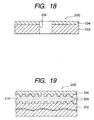
- Fig. 18 is a schematic sectional view of a structure of a playback-only double layer disk.
- the playback-only double layer disk 200 has a base substrate 202 of 1.1 mm thickness, and a light transmitting layer 204 of 0.1 mm thickness is formed on one surface of the base substrate 202.
- Fig. 19 is an enlarged view of a boundary between the base substrate and the light transmitting layer in Fig. 18.
- the base substrate 202 and the light transmitting layer 204 each have an information pit 208 formed in a spiral fashion around a central hole 206 (see Fig. 18).
- a reflective layer (not shown) is provided by spattering or vapor deposition, and between information pits 208 that face each other, a resin layer 210 is formed so as to fill an uneven area formed by the information pits 208.
- a laser beam is applied from above the light transmitting layer 204 for reading.
- the information pit 208 or a groove structure in a surface of the resin layer 210 of the above described multilayer disk a variety of manufacturing methods are used.
- Figs. 20 and 21 illustrate a procedure for forming the information pit using spin coating.
- the base substrate 202 and a light transmitting stamper 212 are first placed so that the information pits 208 thereof face each other. Then, ultraviolet curable resin is introduced into a gap between the base substrate 202 and the stamper 212 from the inside thereof, and the base substrate 202 and the stamper 212 are rotated around the central hole 206 as indicated by an arrow 214.
- the base substrate 202 and the stamper 212 are thus rotated to allow the ultraviolet curable resin to expand toward an outer periphery of the disk by centrifugal force and fill the gap between the base substrate 202 and the stamper 212. After the gap is filled with the ultraviolet curable resin, ultraviolet light is applied from above the stamper 212 to cure the ultraviolet curable resin and thus form a resin layer 216.
- the stamper 212 is raised as shown in Fig. 21 to delaminate the stamper 212 from the resin layer 216.
- the stamper 212 is thus delaminated from the resin layer 216, the information pit 208 transferred from the stamper 212 to the surface of the resin layer 216 is exposed.
- a reflective layer may be then formed on a surface of the resin layer 216 by spattering or vapor deposition, and then a light transmitting layer may be formed by a method such as spin coating.
- the stamper 212 when the stamper 212 is delaminated from the resin layer 210, a large tensile force is needed to simultaneously separate the entire stamper 212 from the resin layer 210. Also, after the stamper 212 is separated from the resin layer 210, the tensile force is suddenly released, and thus the delaminated stamper 212 may be detached from a holding portion and fall onto the resin layer 210 to damage the information pit or the groove structure 208.
- the stamper 212 is simultaneously delaminated from the resin layer 210, and thus it is difficult to adjust a delamination speed of the stamper 212 from the resin layer 210 and set an optimum delamination speed to expose the groove structure 208.
- the invention notes the above described conventional problems and has an object to provide a stamper delaminating method and a stamper delaminating device capable of adjusting a delamination speed of the stamper from a resin layer and setting an optimum delamination speed, as well as a multilayer recording medium.
- the invention is achieved based on findings that a stamper can be delaminated with a slight force not by simultaneously delaminating the stamper from a resin layer but by starting delaminating the stamper from any direction and gradually performing the delamination circumferentially, and that the delamination is performed circumferentially to increase quality of an information pit or a groove structure.
- a stamper delaminating method is a stamper delaminating. method for delaminating a stamper from a resin layer, the stamper being formed to have a larger diameter than at least the disk and laminated via the resin layer so as to cover a surface of a disk having at least one recording layer on a supporting substrate having an information recording surface, including the steps of: after securing the disk, applying a pressing force that acts in a delamination direction of the stamper to any position on the stamper extending beyond an outer edge of the disk; and after the pressing force causes the stamper to start to be delaminated from the resin layer, continuously applying the pressing force to the stamper along a periphery thereof to cause delamination of the stamper from the resin layer circumferentially of the disk.
- stamper delaminating method is a stamper delaminating method for delaminating a stamper from a resin layer after forming the resin layer between a disk and the stamper by spin coating, the stamper being formed to have a larger diameter than at least the disk having at least one recording layer, on a supporting substrate having an information recording surface, and being overlaid so as to cover a surface of the disk, including the steps of: setting a position of an edge so that an excess portion exposed to an outside of the disk is left on the stamper side after being cut; after the edge is circumferentially moved along a boundary between the disk and the resin layer to expose the boundary, securing the disk; applying a pressing force that acts in a delamination direction of the stamper to any position on the stamper extending beyond an outer edge of the disk; and after the pressing force causes the stamper to start to be delaminated from the resin layer, continuously applying the pressing force to the stamper along a periphery thereof to cause delamination of the stamper from the resin layer circumfer
- a further stamper delaminating method is a stamper delaminating method for delaminating a stamper from a resin layer after forming the resin layer between a disk and the stamper by spin coating, the stamper being formed to have a larger diameter than at least the disk having at least one recording layer, on a supporting substrate having an information recording surface, and being overlaid so as to cover a surface of the disk, including the steps of: setting a position of an edge so that an excess portion exposed to an outside of the disk is left on the stamper side after being cut; after the edge is circumferentially moved along a boundary between the disk and the resin layer to expose the boundary, securing the disk; applying a pressing force that acts in a delamination direction of the stamper to any position on the stamper extending beyond an outer edge of the disk; after the pressing force causes the stamper to start to be delaminated from the resin layer, continuously applying the pressing force to the stamper along a periphery thereof to cause delamination of the stamper from the resin layer circum
- a stamper delaminating device is a stamper delaminating device for delaminating a stamper from a resin layer, the stamper being formed to have a larger diameter than at least the disk and laminated via the resin layer so as to cover a surface of a disk having at least one recording layer on a supporting substrate having an information recording surface, comprising securing means for holding the disk, a plurality of pressing pins movable up and down in a delamination direction of the stamper placed along a periphery of the stamper extending beyond an outer edge of the disk, and control means for causing the pressing pins to be pressed on the stamper circumferentially of the disk and adjusting an up-and-down movement speed of the pressing pins.
- stamper delaminating device for delaminating a stamper from a resin layer after forming the resin layer between a disk and the stamper by spin coating, the stamper being formed to have a larger diameter than at least the disk having at least one recording layer, on a supporting substrate having an information recording surface, and being overlaid so as to cover a surface of the disk, comprising an angle adjusting portion that changes a position of an edge in a pivoting manner, a reciprocating portion that allows the edge to approach and be separated from a boundary between the disk and the resin layer, securing means for holding the disk, a plurality of pressing pins movable up and down in a delamination direction of the stamper placed along a periphery of the stamper extending beyond an outer edge of the disk, and control means for causing the pressing pins to be pressed on the stamper circumferentially of the disk and adjusting an up-and-down movement speed of the pressing pins.
- a further stamper delaminating device is a stamper delaminating device for delaminating a stamper from a resin layer after forming the resin layer between a disk and the stamper by spin coating, the stamper being formed to have a larger diameter than at least the disk having at least one recording layer, on a supporting substrate having an information recording surface, and being overlaid so as to cover a surface of the disk, comprising an angle adjusting portion that changes a position of an edge in a pivoting manner, a reciprocating portion that allows the edge to approach and be separated from a boundary between the disk and the resin layer, a chamfering portion that can approach and be separated from the resin layer side of an outer periphery of the disk, securing means for holding the disk, a plurality of pressing pins movable up and down in a delamination direction of the stamper placed along a periphery of the stamper extending beyond an outer edge of the disk, and control means for causing the pressing pins to be pressed on the stamper circumfer
- the pressing pins each are preferably provided with a guide portion for holding an outer edge of the stamper.
- a multilayer recording medium according to the invention is manufactured by the above described stamper delaminating device.
- Fig. 1 is a schematic plan view of a groove forming device to which a stamper delaminating device according to an embodiment is applied as a stamper delaminating portion.
- the device having the stamper delaminating portion is the groove forming device.
- the device is, however, not limited to forming a groove structure, but may form an information pit circumferentially of a disk instead of the groove structure, or a combination of the groove structure and the information pit.
- the groove forming device 230 to which the stamper delaminating device according to the embodiment is applied as the delaminating portion forms a groove structure in an upper layer recording side of a playback-only double layer disk as a multilayer recording medium. As shown in Fig.
- the groove forming device 230 includes a disk and stamper supplying portion 232 for supplying a disk and a stamper into the device, a cleaner portion 234 for cleaning a surface of the disk, a stamper laminating portion 236 for laminating the stamper to the disk, an ultraviolet light applying portion 238 for curing ultraviolet curable resin between the disk and the stamper to form a resin layer, a stamper delaminating portion 240 for delaminating the stamper from the disk, and a disk ejecting portion 242 for ejecting the disk and the stamper. Between these components, a supply arm 244, a first transfer arm 246, a second transfer arm 248, and an ejecting arm 250 are provided, and these arms pivot to allow the disk and the stamper to be conveyed to subsequent stages.
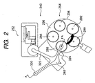
- Fig. 2 is an enlarged view of the stamper delaminating portion in Fig. 1
- Fig. 3 is a sectional view taken along the line A-A in Fig. 2.
- the stamper delaminating portion 240 includes a delaminating station 252 and a conveying table portion 254.
- the disk and the stamper laminated to each other are first conveyed to the delaminating station 252, where a cut is made in a laminated portion of the disk and the stamper. Then, the disk and the stamper are conveyed to the conveying table portion 254, where the stamper is delaminated from the disk, and an end surface of the disk after the delamination is polished.
- the conveyance from the delaminating station 252 to the conveying table portion 254 is performed by the above described second transfer arm 248 pivoting and moving up and down.
- Fig. 4 is a side view of a structure of the delaminating station.
- the delaminating station 252 is provided with a table 256 on a top thereof that has substantially the same size as an outer diameter of the disk and can be sucked by a vacuum.
- a positioning pin 260 that can fit in the central holes of the disk and the stamper extends from the center of the table 256, and fitting the disk and the stamper over the positioning pin 260 allows the disk to be positioned relative to the table 256, allows a back side of the disk to be brought into close contact with a surface of the table 256, and allows the disk and the like to be secured to the table by vacuum suction.
- a disk rotating motor 264 On a side opposite from the positioning pin 260 on the table 256, a disk rotating motor 264 is provided via a rotation axis 262.
- rotating the disk rotating motor 264 causes a rotation force generated in the disk rotating motor 264 to be transmitted to the table 256 via the rotation axis 262, and the disk and the like secured by the vacuum suction can be rotated around the positioning pin 260 together with the table 256.
- an optical sensor 266 (or a sensor of a different type) that detects the rotation of the disk rotating motor 264 is provided, and a below described cutter is advanced and retracted based on values from the optical sensor 266.
- an angle adjusting portion 268 is placed on a side of the table 256.
- the angle adjusting portion 268 is provided with a guide rail 270 curved into an arc and a stage 272 movable along the guide rail 270.
- the curved shape of the guide rail 270 is set so that when the below described cutter secured on the stage 272 is advanced, an edge of the cutter reaches the boundary between the disk and the stamper at any angles.
- FIG. 5 is an enlarged view of essential portions of the edge of the cutter reaching the boundary between the disk and the stamper. As shown in Fig. 5, in a disk 278 and a stamper 280 laminated to each other using spin coating, a member for forming a resin layer extends beyond an outer edge of the disk 278, which is cured to form an excess portion 282.
- the excess portion 282 is located so as to fill a boundary between the disk 278 and the stamper 280, and if the stamper 280 is to be delaminated from the disk 278 without removing the excess portion 282, a force sufficient for separating the excess portion 282 is needed.
- the cutter 276 is pressed into the excess portion 282 to first cause the edge to reach the boundary, after the edge reaches the boundary, the disk rotating motor 264 is driven, and the disk and the like are rotated together with the table 256 at least one turn to cut part of the excess portion 282 by the cutter 276 and expose the boundary. The cut is thus made in the excess portion 282 by the cutter 276 to separate the excess portion 282, thereby preventing the excess portion 282 from affecting delamination strength when the stamper 280 is delaminated.
- a position of the cutter 276 is desirably set so that an angle 284 that the cutter 276 makes with the stamper 280 is as large as possible. Setting a large angle 284 allows a remainder of the excess portion 282 to be positively left on the stamper 280, and the remainder can be easily removed together with the stamper 280 in a subsequent step. Also, an unshown antistatic nozzle is mounted near the cutter 276, and in making the cut by the cutter 276, air is sprayed onto the edge to eliminate static generated in the cut.
- the conveying table portion 254 includes a receiving portion 286 for receiving the disk 278 and the stamper 280, a stamper delaminating portion 288 for delaminating the stamper 280 from the disk 278, an end surface processing portion 290 for processing an end surface of the disk after the delamination, a thickness checking portion 292 for measuring a thickness of the resin layer formed on the surface of the disk 278, and an ejecting portion 294 for passing the disk 278 from the conveying table portion 254 to the disk ejecting portion 242.
- the conveyance of the disk and the like from the receiving portion 286 to the disk ejecting portion 294 is performed by a conveying table 296 rotating and moving up and down. Further, the conveyance of the disk and the like from the delaminating station 252 to the conveying table portion 254, and the removal of the stamper 280 delaminated from the disk are performed by the second transfer arm 248.
- the receiving portion 286 in the conveying table portion 254 is provided, on a center thereof, with a positioning pin for positioning the disk 278 and the stamper 280.
- Operating the second transfer arm 248 allows the disk 278 and the like on the delaminating station 252 to be moved to the receiving portion 286 and held in the receiving portion 286 using the positioning pin.
- Fig. 6 is a partial side view of a structure of the stamper delaminating portion.
- the stamper delaminating portion 288 is provided with a table 298 on a top thereof that has a size slightly smaller than the outer diameter of the disk and can be sucked by a vacuum.
- a positioning pin 300 that can fit in the central holes of the disk and the stamper extends from the center of the table 298, and fitting the disk 278 and the stamper 280 over the positioning pin 300 allows the disk to be positioned relative to the table 298, allows a back side of the disk to be brought into close contact with a surface of the table 298, and allows the disk and the like to be secured to the table by vacuum suction.
- three delamination pins 302 are provided at 120° intervals in an area between the outer diameter of the disk 278 and the outer diameter of the stamper 280.
- the delamination pins 302 are connected to a servomotor 304 placed below the table 298, and operating the servomotor 304 allows tips of the delamination pins 302 to be moved up and down passing through the height of the table 298.
- the delamination pins 302 placed on the three spots on the outer periphery of the disk 278 can be moved up and down by the single servomotor 304, but the tips are set to have different heights.
- Unshown control means is also connected to the servomotor 304. This allows a speed of the servomotor 304 to be adjusted by the control means, so that the speed of the delamination pins 302 that press the stamper 280 can be optimally adjusted.
- a first delamination pin 302a first comes into contact with a surface of the stamper 280.
- Fig. 7 is an enlarged view of essential portions in Fig. 6 showing a state immediately after the delamination pin comes into contact with the stamper.
- the first delamination pin 302a comes into contact with the stamper 280 and then presses the stamper 280
- delamination occurs between the stamper 280 and a resin layer 306, and a surface of the resin layer 306 starts to be exposed.
- a second delamination pin 302b comes into contact with the surface of the stamper 280 and presses a spot separate from the first delamination pin 302.
- a third delamination pin 302c comes into contact with the surface of the stamper 280 and delaminates the stamper 280 together with the first and second delamination pins.
- the delamination pins thus continuously come into contact with the stamper 280 along the outer edge thereof, so that the stamper 280 is delaminated from the resin layer 306 circumferentially of the resin layer 306.
- the delamination of the stamper 280 is performed correspondingly to a groove structure formed in the surface of the resin layer 306 to prevent an uneven area in the stamper 280 from interfering with the groove structure in the resin layer, thereby forming a uniform groove structure in the resin layer.
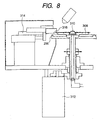
- Fig. 8 is a side view of a structure of the end surface processing portion
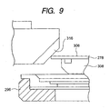
- Fig. 9 is an enlarged view of essential portions in Fig. 8.
- the end surface processing portion 290 is provided with a table 308 on a top thereof that has a size slightly smaller than the outer diameter of the disk and can be sucked by a vacuum.
- a positioning pin 310 that can fit in the central holes of the disk and the stamper extends from the center of the table 308, and fitting the disk 278 after the delamination over the positioning pin 310 allows the disk 278 to be positioned relative to the table 308, allows a back side of the disk 278 to be brought into close contact with a surface of the table 308, and allows the disk to be secured to the table by vacuum suction.
- a disk rotating motor 312 is also provided below the table 308, and the disk rotating motor 312 and the table 308 are connected via a power transmission mechanism. Thus, operating the disk rotating motor 312 allows the table 308 to which the disk 278 is sucked to be rotated.
- a cutter reciprocating cylinder 314 as a reciprocating portion and a cutter 316 as a chamfering portion incorporated in the cutter reciprocating cylinder 314 are provided on a side of the table 308, a cutter reciprocating cylinder 314 as a reciprocating portion and a cutter 316 as a chamfering portion incorporated in the cutter reciprocating cylinder 314 are provided. Reciprocating the cutter reciprocating cylinder 314 allows the cutter 316 to be pressed on the resin layer 306 at the outer edge of the disk 278. Chamfering the resin layer 306 at the outer edge of the disk 278 allows the end surface of the resin layer 306 to be processed and allows the excess portion 282 left on the end surface of the outer edge of the disk 278 to be cut away.
- An antistatic nozzle 317 is provided above the disk 278, and an unshown exhaust duct is provided on an opposite side of the disk 278.
- air is sprayed from the antistatic nozzle 317 to the disk 278 to blow off shavings and also eliminate static.
- Such spraying of the air prevents the shavings from depositing on the surface of the disk 278 (that is, the surface of the resin layer 306).
- the shavings blown off by the air may be exhausted out of the device by the exhaust duct.
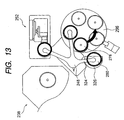
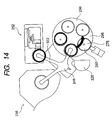
- Figs. 10 to 15 illustrate states of the disk and the stamper passing through the stamper delaminating portion.
- the disk and the stamper 318 having passed through the ultraviolet light applying portion 238 are conveyed by rotating the second transfer arm 248 and using the first arm 320 from the ultraviolet light applying portion 238 to the delaminating station 252. Then, the cutter 276 is pressed on the disk and the stamper 318 as described above in the delaminating station. 252 to allow the excess portion 282 to be cut away to expose the boundary between the disk and the stamper.
- the second transfer arm 248 is rotated, and the disk and the stamper 318 are conveyed from the delaminating station 252 to the receiving portion 286 of the conveying table portion 254 by the second arm 322 in the second transfer arm 248.
- the state of the disk and the stamper 318 conveyed to the receiving portion 286 is shown in Fig. 11.
- the conveying table 296 is moved up to raise the disk and the stamper 318, and then the disk and the stamper 318 are moved to the stamper delaminating portion 288 by the rotation of the conveying table 296.
- the delamination pins 302 are pressed on the stamper 280 to delaminate the stamper 280 from the disk 278 as described above.
- a stamper ejecting arm 324 of the second transfer arm 248 is moved down from above as shown in Fig. 12 to grip the stamper 280 only.
- the delaminated stamper 280 is gripped by the stamper ejecting arm 324, the delaminated stamper 280 is moved onto a stamper disposal portion 326 placed outside the conveying table 296 as shown in Fig. 13, and then the stamper 280 may be passed to a stamper ejecting chute 450.
- the disk 278 from which the stamper 280 is delaminated is conveyed to the end surface processing portion 290 in a subsequent stage by the conveying table 296 moving up and down and rotating as shown in Fig. 14. Then, in the end surface processing portion 290, the cutter 316 may be pressed on the end surface of the disk 278 to remove the excess portion 282 left on the end surface of the disk 278.
- the conveying table 296 is again moved up and down and rotated to convey the disk 278 to the thickness checking portion 292 as shown in Fig. 15. Then, a thickness of the resin layer 306 is checked in the thickness checking portion 292, and after it is confirmed whether the thickness of the resin layer 306 formed on the disk 278 is within a set value, the result is stored in unshown recording means, and the disk 278 is conveyed to the next stage, the ejecting portion 294.
- the ejecting arm 250 is used to take the disk 278 out of the stamper delaminating portion 240, and screening of the disk 278 into a good product or a bad product may be performed in the disk ejecting portion 242.
- Fig. 16 illustrates a delaminating state of the stamper.
- the delamination pin 302a first comes into contact with the stamper 280, and then the delamination pin 302b and the delamination pin 302c come into contact with the stamper 280 in succession. Then, according to the order of contact of the delamination pins, the stamper 280 is delaminated from the disk 278 as indicated by an arrow 328 in Fig. 16.
- the delamination is performed along an extending direction of the groove structure formed in the resin layer 306 (and the stamper 280), thus preventing adjacent grooves (and lands) from being affected by the delamination of the stamper 280.
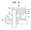
- Fig. 17 is an enlarged view of essential portions of an example application of the stamper delaminating portion.
- the delamination pin 302 is provided with a protrusion 330 on an outside of an area with which the stamper 280 comes into contact. Even if the stamper 280 is raised as indicated by a broken line by elastic deformation being released when the stamper 280 is delaminated from the disk 278, the protrusion 330 provided on the tip of the delamination pin 302 holds the raised stamper 280, thus preventing failures such that the raised stamper 280 is out of position to collide with the disk 278.
- the multilayer recording medium delaminated using the method and the device has a clear groove structure formed therein, thereby increasing reliability.
- the three delamination pins are used to delaminate the stamper from the disk, but not limited to this, the number of the delamination pins may be increased, or servo motors for moving up and down the delamination pins may be prepared as many as the delamination pins to control the delamination speed or the like of the stamper 280 more accurately.
- the pressing force is continuously applied along the periphery of the stamper so that the delamination of the stamper from the resin layer is performed circumferentially of the disk.
- the delamination caused by the first pressing pin is gradually increased so that only slight pressing forces are required for the second pressing pin and thereafter.
- the delamination of the stamper is performed circumferentially of the disk, specifically along the information pit or the groove in a concentric or spiral fashion formed in the surface of the resin layer, so that the delamination direction substantially corresponds to an arrangement direction of the information pit and a tangential direction of the groove structure.
- the information pit or the groove structure in the stamper when delaminated is prevented from interfering with the information pit or the groove structure in the resin layer that fits an uneven area formed by the information pit or the groove structure in the stamper, thereby forming a uniform information pit or a uniform groove structure in the resin layer.
Landscapes
- Engineering & Computer Science (AREA)
- Manufacturing & Machinery (AREA)
- Manufacturing Optical Record Carriers (AREA)
- Moulds For Moulding Plastics Or The Like (AREA)
- Casting Or Compression Moulding Of Plastics Or The Like (AREA)
- Manufacturing Of Magnetic Record Carriers (AREA)
Abstract
There are provided a stamper delaminating
method and a stamper delaminating device for
delaminating a stamper from a resin layer, the
stamper being formed to have a larger diameter than
at least the disk and laminated via the resin layer
so as to cover a surface of a disk having at least
one recording layer on a supporting substrate having
an information recording surface. After the disk is
secured, a pressing force that acts in a delamination
direction of the stamper is applied to any position
on the stamper extending beyond an outer edge of the
disk, and after the pressing force causes the stamper
to start to be delaminated from the resin layer, the
pressing force is continuously applied to the stamper
along a periphery thereof. The delamination of the
stamper from the resin layer is performed
circumferentially of the disk, so that the
delamination direction substantially corresponds to
an arrangement direction of an information pit and a
tangential direction of a groove structure, thereby
forming a uniform information pit or a uniform groove
structure in the resin layer.
Description
The present invention relates to a stamper
delaminating method and a stamper delaminating device,
and more particularly relates to a stamper
delaminating device method and a stamper delaminating
device capable of forming a pit and/or a groove
structure in a delamination surface of a disk, as
well as a multilayer recording medium manufactured by
the device.
Recently, a variety of disks with a multilayer
structure have been proposed as next-generation
recording media.
Fig. 18 is a schematic sectional view of a
structure of a playback-only double layer disk. As
shown in Fig. 18, the playback-only double layer disk
200 has a base substrate 202 of 1.1 mm thickness, and
a light transmitting layer 204 of 0.1 mm thickness is
formed on one surface of the base substrate 202.
Fig. 19 is an enlarged view of a boundary
between the base substrate and the light transmitting
layer in Fig. 18. As shown in Fig. 19, the base
substrate 202 and the light transmitting layer 204
each have an information pit 208 formed in a spiral
fashion around a central hole 206 (see Fig. 18). On
a surface of the information pit 208, a reflective
layer (not shown) is provided by spattering or vapor
deposition, and between information pits 208 that
face each other, a resin layer 210 is formed so as to
fill an uneven area formed by the information pits
208.
For the multilayer disk thus config.d, a laser
beam is applied from above the light transmitting
layer 204 for reading.
In forming the information pit 208 or a groove
structure in a surface of the resin layer 210 of the
above described multilayer disk, a variety of
manufacturing methods are used.
Figs. 20 and 21 illustrate a procedure for
forming the information pit using spin coating. In
forming the information pit using the spin coating,
as shown in Fig. 20, the base substrate 202 and a
light transmitting stamper 212 are first placed so
that the information pits 208 thereof face each other.
Then, ultraviolet curable resin is introduced into a
gap between the base substrate 202 and the stamper
212 from the inside thereof, and the base substrate
202 and the stamper 212 are rotated around the
central hole 206 as indicated by an arrow 214.
The base substrate 202 and the stamper 212 are
thus rotated to allow the ultraviolet curable resin
to expand toward an outer periphery of the disk by
centrifugal force and fill the gap between the base
substrate 202 and the stamper 212. After the gap is
filled with the ultraviolet curable resin,
ultraviolet light is applied from above the stamper
212 to cure the ultraviolet curable resin and thus
form a resin layer 216.
After the resin layer 216 is formed, the
stamper 212 is raised as shown in Fig. 21 to
delaminate the stamper 212 from the resin layer 216.
When the stamper 212 is thus delaminated from the
resin layer 216, the information pit 208 transferred
from the stamper 212 to the surface of the resin
layer 216 is exposed. Thus, a reflective layer may
be then formed on a surface of the resin layer 216 by
spattering or vapor deposition, and then a light
transmitting layer may be formed by a method such as
spin coating.
In the above described conventional example,
the procedure for forming the information pit 208 in
the surface of the resin layer 216 has been described.
This method using the stamper, however, is not
applied in a limited manner to forming the
information pit 208, but may be, of course, applied
to forming a groove structure circumferentially of
the disk or a combination of the groove structure and
the information pit.
However, the method for forming the information
pit or the groove structure in the surface of the
resin layer using the stamper has problems as
described below.
Specifically, when the stamper 212 is
delaminated from the resin layer 210, a large tensile
force is needed to simultaneously separate the entire
stamper 212 from the resin layer 210. Also, after
the stamper 212 is separated from the resin layer 210,
the tensile force is suddenly released, and thus the
delaminated stamper 212 may be detached from a
holding portion and fall onto the resin layer 210 to
damage the information pit or the groove structure
208.
Further, as described above, the stamper 212 is
simultaneously delaminated from the resin layer 210,
and thus it is difficult to adjust a delamination
speed of the stamper 212 from the resin layer 210 and
set an optimum delamination speed to expose the
groove structure 208.
The invention notes the above described
conventional problems and has an object to provide a
stamper delaminating method and a stamper
delaminating device capable of adjusting a
delamination speed of the stamper from a resin layer
and setting an optimum delamination speed, as well as
a multilayer recording medium.
The invention is achieved based on findings
that a stamper can be delaminated with a slight force
not by simultaneously delaminating the stamper from a
resin layer but by starting delaminating the stamper
from any direction and gradually performing the
delamination circumferentially, and that the
delamination is performed circumferentially to
increase quality of an information pit or a groove
structure.
Specifically, a stamper delaminating method
according to the invention is a stamper delaminating.
method for delaminating a stamper from a resin layer,
the stamper being formed to have a larger diameter
than at least the disk and laminated via the resin
layer so as to cover a surface of a disk having at
least one recording layer on a supporting substrate
having an information recording surface, including
the steps of: after securing the disk, applying a
pressing force that acts in a delamination direction
of the stamper to any position on the stamper
extending beyond an outer edge of the disk; and after
the pressing force causes the stamper to start to be
delaminated from the resin layer, continuously
applying the pressing force to the stamper along a
periphery thereof to cause delamination of the
stamper from the resin layer circumferentially of the
disk.
Another stamper delaminating method is a
stamper delaminating method for delaminating a
stamper from a resin layer after forming the resin
layer between a disk and the stamper by spin coating,
the stamper being formed to have a larger diameter
than at least the disk having at least one recording
layer, on a supporting substrate having an
information recording surface, and being overlaid so
as to cover a surface of the disk, including the
steps of: setting a position of an edge so that an
excess portion exposed to an outside of the disk is
left on the stamper side after being cut; after the
edge is circumferentially moved along a boundary
between the disk and the resin layer to expose the
boundary, securing the disk; applying a pressing
force that acts in a delamination direction of the
stamper to any position on the stamper extending
beyond an outer edge of the disk; and after the
pressing force causes the stamper to start to be
delaminated from the resin layer, continuously
applying the pressing force to the stamper along a
periphery thereof to cause delamination of the
stamper from the resin layer circumferentially of the
disk.
A further stamper delaminating method is a
stamper delaminating method for delaminating a
stamper from a resin layer after forming the resin
layer between a disk and the stamper by spin coating,
the stamper being formed to have a larger diameter
than at least the disk having at least one recording
layer, on a supporting substrate having an
information recording surface, and being overlaid so
as to cover a surface of the disk, including the
steps of: setting a position of an edge so that an
excess portion exposed to an outside of the disk is
left on the stamper side after being cut; after the
edge is circumferentially moved along a boundary
between the disk and the resin layer to expose the
boundary, securing the disk; applying a pressing
force that acts in a delamination direction of the
stamper to any position on the stamper extending
beyond an outer edge of the disk; after the pressing
force causes the stamper to start to be delaminated
from the resin layer, continuously applying the
pressing force to the stamper along a periphery
thereof to cause delamination of the stamper from the
resin layer circumferentially of the disk; and after
the delamination of the stamper, chamfering a resin
layer side of an outer periphery of the disk.
A stamper delaminating device according to the
invention is a stamper delaminating device for
delaminating a stamper from a resin layer, the
stamper being formed to have a larger diameter than
at least the disk and laminated via the resin layer
so as to cover a surface of a disk having at least
one recording layer on a supporting substrate having
an information recording surface, comprising securing
means for holding the disk, a plurality of pressing
pins movable up and down in a delamination direction
of the stamper placed along a periphery of the
stamper extending beyond an outer edge of the disk,
and control means for causing the pressing pins to be
pressed on the stamper circumferentially of the disk
and adjusting an up-and-down movement speed of the
pressing pins.
Another stamper delaminating device is a
stamper delaminating device for delaminating a
stamper from a resin layer after forming the resin
layer between a disk and the stamper by spin coating,
the stamper being formed to have a larger diameter
than at least the disk having at least one recording
layer, on a supporting substrate having an
information recording surface, and being overlaid so
as to cover a surface of the disk, comprising an
angle adjusting portion that changes a position of an
edge in a pivoting manner, a reciprocating portion
that allows the edge to approach and be separated
from a boundary between the disk and the resin layer,
securing means for holding the disk, a plurality of
pressing pins movable up and down in a delamination
direction of the stamper placed along a periphery of
the stamper extending beyond an outer edge of the
disk, and control means for causing the pressing pins
to be pressed on the stamper circumferentially of the
disk and adjusting an up-and-down movement speed of
the pressing pins.
A further stamper delaminating device is a
stamper delaminating device for delaminating a
stamper from a resin layer after forming the resin
layer between a disk and the stamper by spin coating,
the stamper being formed to have a larger diameter
than at least the disk having at least one recording
layer, on a supporting substrate having an
information recording surface, and being overlaid so
as to cover a surface of the disk, comprising an
angle adjusting portion that changes a position of an
edge in a pivoting manner, a reciprocating portion
that allows the edge to approach and be separated
from a boundary between the disk and the resin layer,
a chamfering portion that can approach and be
separated from the resin layer side of an outer
periphery of the disk, securing means for holding the
disk, a plurality of pressing pins movable up and
down in a delamination direction of the stamper
placed along a periphery of the stamper extending
beyond an outer edge of the disk, and control means
for causing the pressing pins to be pressed on the
stamper circumferentially of the disk and adjusting
an up-and-down movement speed of the pressing pins.
The pressing pins each are preferably provided
with a guide portion for holding an outer edge of the
stamper.
A multilayer recording medium according to the
invention is manufactured by the above described
stamper delaminating device.
Now, preferable embodiments of a stamper
delaminating method and a stamper delaminating device
as well as a multilayer recording medium will be
described in detail with reference to the drawings.
Fig. 1 is a schematic plan view of a groove
forming device to which a stamper delaminating device
according to an embodiment is applied as a stamper
delaminating portion. In this embodiment, the device
having the stamper delaminating portion is the groove
forming device. The device is, however, not limited
to forming a groove structure, but may form an
information pit circumferentially of a disk instead
of the groove structure, or a combination of the
groove structure and the information pit.
The groove forming device 230 to which the
stamper delaminating device according to the
embodiment is applied as the delaminating portion
forms a groove structure in an upper layer recording
side of a playback-only double layer disk as a
multilayer recording medium. As shown in Fig. 1, the
groove forming device 230 includes a disk and stamper
supplying portion 232 for supplying a disk and a
stamper into the device, a cleaner portion 234 for
cleaning a surface of the disk, a stamper laminating
portion 236 for laminating the stamper to the disk,
an ultraviolet light applying portion 238 for curing
ultraviolet curable resin between the disk and the
stamper to form a resin layer, a stamper delaminating
portion 240 for delaminating the stamper from the
disk, and a disk ejecting portion 242 for ejecting
the disk and the stamper. Between these components,
a supply arm 244, a first transfer arm 246, a second
transfer arm 248, and an ejecting arm 250 are
provided, and these arms pivot to allow the disk and
the stamper to be conveyed to subsequent stages.
Fig. 2 is an enlarged view of the stamper
delaminating portion in Fig. 1, and Fig. 3 is a
sectional view taken along the line A-A in Fig. 2.
As shown in Figs. 2 and 3, the stamper
delaminating portion 240 includes a delaminating
station 252 and a conveying table portion 254. The
disk and the stamper laminated to each other are
first conveyed to the delaminating station 252, where
a cut is made in a laminated portion of the disk and
the stamper. Then, the disk and the stamper are
conveyed to the conveying table portion 254, where
the stamper is delaminated from the disk, and an end
surface of the disk after the delamination is
polished. The conveyance from the delaminating
station 252 to the conveying table portion 254 is
performed by the above described second transfer arm
248 pivoting and moving up and down.
Fig. 4 is a side view of a structure of the
delaminating station.
As shown in Fig. 4, the delaminating station
252 is provided with a table 256 on a top thereof
that has substantially the same size as an outer
diameter of the disk and can be sucked by a vacuum.
A positioning pin 260 that can fit in the central
holes of the disk and the stamper extends from the
center of the table 256, and fitting the disk and the
stamper over the positioning pin 260 allows the disk
to be positioned relative to the table 256, allows a
back side of the disk to be brought into close
contact with a surface of the table 256, and allows
the disk and the like to be secured to the table by
vacuum suction.
On a side opposite from the positioning pin 260
on the table 256, a disk rotating motor 264 is
provided via a rotation axis 262. Thus, rotating the
disk rotating motor 264 causes a rotation force
generated in the disk rotating motor 264 to be
transmitted to the table 256 via the rotation axis
262, and the disk and the like secured by the vacuum
suction can be rotated around the positioning pin 260
together with the table 256. At a midpoint of the
rotation axis 262, an optical sensor 266 (or a sensor
of a different type) that detects the rotation of the
disk rotating motor 264 is provided, and a below
described cutter is advanced and retracted based on
values from the optical sensor 266.
On the other hand, an angle adjusting portion
268 is placed on a side of the table 256. The angle
adjusting portion 268 is provided with a guide rail
270 curved into an arc and a stage 272 movable along
the guide rail 270. The curved shape of the guide
rail 270 is set so that when the below described
cutter secured on the stage 272 is advanced, an edge
of the cutter reaches the boundary between the disk
and the stamper at any angles.
A cylinder 274 as a reciprocating portion is
fitted on the stage 272, and the cutter 276 is
mounted to the cylinder 274. Thus, when the cylinder
274 is extended, the cutter 276 is advanced together
with the cylinder 274, and the edge of the cutter 276
reaches the boundary between the disk and the stamper
secured to the table 256. Fig. 5 is an enlarged view
of essential portions of the edge of the cutter
reaching the boundary between the disk and the
stamper. As shown in Fig. 5, in a disk 278 and a
stamper 280 laminated to each other using spin
coating, a member for forming a resin layer extends
beyond an outer edge of the disk 278, which is cured
to form an excess portion 282. Thus, the excess
portion 282 is located so as to fill a boundary
between the disk 278 and the stamper 280, and if the
stamper 280 is to be delaminated from the disk 278
without removing the excess portion 282, a force
sufficient for separating the excess portion 282 is
needed. However, as shown in Fig. 5, the cutter 276
is pressed into the excess portion 282 to first cause
the edge to reach the boundary, after the edge
reaches the boundary, the disk rotating motor 264 is
driven, and the disk and the like are rotated
together with the table 256 at least one turn to cut
part of the excess portion 282 by the cutter 276 and
expose the boundary. The cut is thus made in the
excess portion 282 by the cutter 276 to separate the
excess portion 282, thereby preventing the excess
portion 282 from affecting delamination strength when
the stamper 280 is delaminated.
When the cut is made in the excess portion 282,
a position of the cutter 276 is desirably set so that
an angle 284 that the cutter 276 makes with the
stamper 280 is as large as possible. Setting a large
angle 284 allows a remainder of the excess portion
282 to be positively left on the stamper 280, and the
remainder can be easily removed together with the
stamper 280 in a subsequent step. Also, an unshown
antistatic nozzle is mounted near the cutter 276, and
in making the cut by the cutter 276, air is sprayed
onto the edge to eliminate static generated in the
cut.
As shown in Fig. 2, the conveying table portion
254 includes a receiving portion 286 for receiving
the disk 278 and the stamper 280, a stamper
delaminating portion 288 for delaminating the stamper
280 from the disk 278, an end surface processing
portion 290 for processing an end surface of the disk
after the delamination, a thickness checking portion
292 for measuring a thickness of the resin layer
formed on the surface of the disk 278, and an
ejecting portion 294 for passing the disk 278 from
the conveying table portion 254 to the disk ejecting
portion 242.
The conveyance of the disk and the like from
the receiving portion 286 to the disk ejecting
portion 294 is performed by a conveying table 296
rotating and moving up and down. Further, the
conveyance of the disk and the like from the
delaminating station 252 to the conveying table
portion 254, and the removal of the stamper 280
delaminated from the disk are performed by the second
transfer arm 248.
The receiving portion 286 in the conveying
table portion 254 is provided, on a center thereof,
with a positioning pin for positioning the disk 278
and the stamper 280. Operating the second transfer
arm 248 allows the disk 278 and the like on the
delaminating station 252 to be moved to the receiving
portion 286 and held in the receiving portion 286
using the positioning pin.
Fig. 6 is a partial side view of a structure of
the stamper delaminating portion. As shown in Fig. 6,
like the delaminating station 252, the stamper
delaminating portion 288 is provided with a table 298
on a top thereof that has a size slightly smaller
than the outer diameter of the disk and can be sucked
by a vacuum. A positioning pin 300 that can fit in
the central holes of the disk and the stamper extends
from the center of the table 298, and fitting the
disk 278 and the stamper 280 over the positioning pin
300 allows the disk to be positioned relative to the
table 298, allows a back side of the disk to be
brought into close contact with a surface of the
table 298, and allows the disk and the like to be
secured to the table by vacuum suction. On an
outside of the table 298, three delamination pins 302
are provided at 120° intervals in an area between the
outer diameter of the disk 278 and the outer diameter
of the stamper 280. The delamination pins 302 are
connected to a servomotor 304 placed below the table
298, and operating the servomotor 304 allows tips of
the delamination pins 302 to be moved up and down
passing through the height of the table 298. The
delamination pins 302 placed on the three spots on
the outer periphery of the disk 278 can be moved up
and down by the single servomotor 304, but the tips
are set to have different heights. Unshown control
means is also connected to the servomotor 304. This
allows a speed of the servomotor 304 to be adjusted
by the control means, so that the speed of the
delamination pins 302 that press the stamper 280 can
be optimally adjusted.
Then, when the servomotor 304 is operated to
move the delamination pins 302 up according to a
signal from the control means, a first delamination
pin 302a first comes into contact with a surface of
the stamper 280.
Fig. 7 is an enlarged view of essential
portions in Fig. 6 showing a state immediately after
the delamination pin comes into contact with the
stamper. As shown in Fig. 7, when the first
delamination pin 302a comes into contact with the
stamper 280 and then presses the stamper 280,
delamination occurs between the stamper 280 and a
resin layer 306, and a surface of the resin layer 306
starts to be exposed. When the delamination pin 302a
is moved up and the delamination between the stamper
280 and the resin layer 306 proceeds to a certain
degree, a second delamination pin 302b (see Fig. 16)
comes into contact with the surface of the stamper
280 and presses a spot separate from the first
delamination pin 302. When the delamination between
the stamper 280 and the resin layer 306 proceeds to a
certain degree at the spot of the second delamination
pin 302b, a third delamination pin 302c (see Fig. 16)
comes into contact with the surface of the stamper
280 and delaminates the stamper 280 together with the
first and second delamination pins.
The delamination pins thus continuously come
into contact with the stamper 280 along the outer
edge thereof, so that the stamper 280 is delaminated
from the resin layer 306 circumferentially of the
resin layer 306. Thus, the delamination of the
stamper 280 is performed correspondingly to a groove
structure formed in the surface of the resin layer
306 to prevent an uneven area in the stamper 280 from
interfering with the groove structure in the resin
layer, thereby forming a uniform groove structure in
the resin layer.
Fig. 8 is a side view of a structure of the end
surface processing portion, and Fig. 9 is an enlarged
view of essential portions in Fig. 8.
As shown in Figs. 8 and 9, like the stamper
delaminating portion 288 and the delaminating station
252, the end surface processing portion 290 is
provided with a table 308 on a top thereof that has a
size slightly smaller than the outer diameter of the
disk and can be sucked by a vacuum. A positioning
pin 310 that can fit in the central holes of the disk
and the stamper extends from the center of the table
308, and fitting the disk 278 after the delamination
over the positioning pin 310 allows the disk 278 to
be positioned relative to the table 308, allows a
back side of the disk 278 to be brought into close
contact with a surface of the table 308, and allows
the disk to be secured to the table by vacuum suction.
A disk rotating motor 312 is also provided below the
table 308, and the disk rotating motor 312 and the
table 308 are connected via a power transmission
mechanism. Thus, operating the disk rotating motor
312 allows the table 308 to which the disk 278 is
sucked to be rotated.
On a side of the table 308, a cutter
reciprocating cylinder 314 as a reciprocating portion
and a cutter 316 as a chamfering portion incorporated
in the cutter reciprocating cylinder 314 are provided.
Reciprocating the cutter reciprocating cylinder 314
allows the cutter 316 to be pressed on the resin
layer 306 at the outer edge of the disk 278.
Chamfering the resin layer 306 at the outer edge of
the disk 278 allows the end surface of the resin
layer 306 to be processed and allows the excess
portion 282 left on the end surface of the outer edge
of the disk 278 to be cut away.
An antistatic nozzle 317 is provided above the
disk 278, and an unshown exhaust duct is provided on
an opposite side of the disk 278. Thus, during the
end surface processing of the disk 278 by the cutter
316, air is sprayed from the antistatic nozzle 317 to
the disk 278 to blow off shavings and also eliminate
static. Such spraying of the air prevents the
shavings from depositing on the surface of the disk
278 (that is, the surface of the resin layer 306).
The shavings blown off by the air may be exhausted
out of the device by the exhaust duct.
A procedure for delaminating the stamper from
the disk using the stamper delaminating portion thus
conFig.d will be described.
Figs. 10 to 15 illustrate states of the disk
and the stamper passing through the stamper
delaminating portion.
First, as shown in Fig. 10, the disk and the
stamper 318 having passed through the ultraviolet
light applying portion 238 are conveyed by rotating
the second transfer arm 248 and using the first arm
320 from the ultraviolet light applying portion 238
to the delaminating station 252. Then, the cutter
276 is pressed on the disk and the stamper 318 as
described above in the delaminating station. 252 to
allow the excess portion 282 to be cut away to expose
the boundary between the disk and the stamper.
After the excess portion 282 is cut away in the
delaminating station 252 to expose the boundary
between the disk and the stamper, the second transfer
arm 248 is rotated, and the disk and the stamper 318
are conveyed from the delaminating station 252 to the
receiving portion 286 of the conveying table portion
254 by the second arm 322 in the second transfer arm
248. The state of the disk and the stamper 318
conveyed to the receiving portion 286 is shown in Fig.
11.
After the disk and the stamper 318 are conveyed
to the receiving portion 286, the conveying table 296
is moved up to raise the disk and the stamper 318,
and then the disk and the stamper 318 are moved to
the stamper delaminating portion 288 by the rotation
of the conveying table 296. When the disk and the
stamper 318 are thus moved to the stamper
delaminating portion 288, the delamination pins 302
are pressed on the stamper 280 to delaminate the
stamper 280 from the disk 278 as described above.
Then, with the stamper 280 delaminated from the disk
278 being supported by the delamination pins 302, a
stamper ejecting arm 324 of the second transfer arm
248 is moved down from above as shown in Fig. 12 to
grip the stamper 280 only.
After the delaminated stamper 280 is gripped by
the stamper ejecting arm 324, the delaminated stamper
280 is moved onto a stamper disposal portion 326
placed outside the conveying table 296 as shown in
Fig. 13, and then the stamper 280 may be passed to a
stamper ejecting chute 450.
The disk 278 from which the stamper 280 is
delaminated is conveyed to the end surface processing
portion 290 in a subsequent stage by the conveying
table 296 moving up and down and rotating as shown in
Fig. 14. Then, in the end surface processing portion
290, the cutter 316 may be pressed on the end surface
of the disk 278 to remove the excess portion 282 left
on the end surface of the disk 278.
After the excess portion 282 left on the end
surface of the disk 278 is removed in the end surface
processing portion 290, the conveying table 296 is
again moved up and down and rotated to convey the
disk 278 to the thickness checking portion 292 as
shown in Fig. 15. Then, a thickness of the resin
layer 306 is checked in the thickness checking
portion 292, and after it is confirmed whether the
thickness of the resin layer 306 formed on the disk
278 is within a set value, the result is stored in
unshown recording means, and the disk 278 is conveyed
to the next stage, the ejecting portion 294. After
the disk 278 is conveyed to the ejecting portion 294,
the ejecting arm 250 is used to take the disk 278 out
of the stamper delaminating portion 240, and
screening of the disk 278 into a good product or a
bad product may be performed in the disk ejecting
portion 242.
The state of one disk 278 (and one stamper 280)
passing through the stamper delaminating portion is
described above, but it is to be understood that, in
an actual operation, the three arms provided in the
second transfer arm 248 act simultaneously, and a
plurality of disks 278 (and stampers 280) pass
through the stamper delaminating portion.
Fig. 16 illustrates a delaminating state of the
stamper. As shown in Fig. 16, when the stamper 280
is to be delaminated, the delamination pin 302a first
comes into contact with the stamper 280, and then the
delamination pin 302b and the delamination pin 302c
come into contact with the stamper 280 in succession.
Then, according to the order of contact of the
delamination pins, the stamper 280 is delaminated
from the disk 278 as indicated by an arrow 328 in Fig.
16. When the stamper 280 is delaminated along the
arrow 328, the delamination is performed along an
extending direction of the groove structure formed in
the resin layer 306 (and the stamper 280), thus
preventing adjacent grooves (and lands) from being
affected by the delamination of the stamper 280.
Fig. 17 is an enlarged view of essential
portions of an example application of the stamper
delaminating portion.
As shown in Fig. 17, the delamination pin 302
is provided with a protrusion 330 on an outside of an
area with which the stamper 280 comes into contact.
Even if the stamper 280 is raised as indicated by a
broken line by elastic deformation being released
when the stamper 280 is delaminated from the disk 278,
the protrusion 330 provided on the tip of the
delamination pin 302 holds the raised stamper 280,
thus preventing failures such that the raised stamper
280 is out of position to collide with the disk 278.
Thus, the multilayer recording medium delaminated
using the method and the device has a clear groove
structure formed therein, thereby increasing
reliability.
In the embodiment, the three delamination pins
are used to delaminate the stamper from the disk, but
not limited to this, the number of the delamination
pins may be increased, or servo motors for moving up
and down the delamination pins may be prepared as
many as the delamination pins to control the
delamination speed or the like of the stamper 280
more accurately.
As described above, according to the invention,
the pressing force is continuously applied along the
periphery of the stamper so that the delamination of
the stamper from the resin layer is performed
circumferentially of the disk. Thus, the
delamination caused by the first pressing pin is
gradually increased so that only slight pressing
forces are required for the second pressing pin and
thereafter. Further, the delamination of the stamper
is performed circumferentially of the disk,
specifically along the information pit or the groove
in a concentric or spiral fashion formed in the
surface of the resin layer, so that the delamination
direction substantially corresponds to an arrangement
direction of the information pit and a tangential
direction of the groove structure. Therefore, the
information pit or the groove structure in the
stamper when delaminated is prevented from
interfering with the information pit or the groove
structure in the resin layer that fits an uneven area
formed by the information pit or the groove structure
in the stamper, thereby forming a uniform information
pit or a uniform groove structure in the resin layer.
Claims (9)
- A stamper delaminating method for delaminating a stamper from a resin layer, the stamper being formed to have a larger diameter than at least the disk and laminated via the resin layer so as to cover a surface of a disk having at least one recording layer on a supporting substrate having an information recording surface, characterized by comprising the steps of:after securing said disk, applying a pressing force that acts in a delamination direction of said stamper to any position on said stamper extending beyond an outer edge of said disk; andafter said pressing force causes said stamper to start to be delaminated from said resin layer, continuously applying the pressing force to said stamper along a periphery thereof to cause delamination of said stamper from said resin layer circumferentially of said disk.
- A stamper delaminating method for delaminating a stamper from a resin layer after forming the resin layer between a disk and the stamper by spin coating, the stamper being formed to have a larger diameter than at least the disk having at least one recording layer, on a supporting substrate having an information recording surface, and being overlaid so as to cover a surface of the disk, characterized by comprising the steps of:setting a position of an edge so that an excess portion exposed to an outside of said disk is left on said stamper side after being cut;after said edge is circumferentially moved along a boundary between said disk and said resin layer to expose said boundary, securing said disk;applying a pressing force that acts in a delamination direction of said stamper to any position on said stamper extending beyond an outer edge of said disk; andafter said pressing force causes said stamper to start to be delaminated from said resin layer, continuously applying the pressing force to said stamper along a periphery thereof to cause delamination of said stamper from said resin layer circumferentially of said disk.
- A stamper delaminating method for delaminating a stamper from a resin layer after forming the resin layer between a disk and the stamper by spin coating, the stamper being formed to have a larger diameter than at least the disk having at least one recording layer, on a supporting substrate having an information recording surface, and being overlaid so as to cover a surface of the disk, characterized by comprising the steps of:setting a position of an edge so that an excess portion exposed to an outside of said disk is left on said stamper side after being cut;after said edge is circumferentially moved along a boundary between said disk and said resin layer to expose said boundary, securing said disk;applying a pressing force that acts in a delamination direction of said stamper to any position on said stamper extending beyond an outer edge of said disk;after said pressing force causes said stamper to start to be delaminated from said resin layer, continuously applying the pressing force to said stamper along a periphery thereof to cause delamination of said stamper from said resin layer circumferentially of said disk; andafter the delamination of said stamper, chamfering said resin layer side of an outer periphery of said disk.
- A stamper delaminating device for delaminating a stamper from a resin layer, the stamper being formed to have a larger diameter than at least the disk and laminated via the resin layer so as to cover a surface of a disk having at least one recording layer on a supporting substrate having an information recording surface,
characterized by comprising:securing means for holding said disk;a plurality of pressing pins movable up and down in a delamination direction of said stamper placed along a periphery of said stamper extending beyond an outer edge of said disk; andcontrol means for causing the pressing pins to be pressed on said stamper circumferentially of said disk and adjusting an up-and-down movement speed of said pressing pins. - A stamper delaminating device for delaminating a stamper from a resin layer after forming the resin layer between a disk and the stamper by spin coating, the stamper being formed to have a larger diameter than at least the disk having at least one recording layer, on a supporting substrate having an information recording surface, and being overlaid so as to cover a surface of the disk,
characterized by comprising:an angle adjusting portion that changes a position of an edge in a pivoting manner;a reciprocating portion that allows said edge to approach and be separated from a boundary between said disk and said resin layer;securing means for holding said disk;a plurality of pressing pins movable up and down in a delamination direction of said stamper placed along a periphery of said stamper extending beyond an outer edge of said disk; andcontrol means for causing the pressing pins to be pressed on said stamper circumferentially of said disk and adjusting an up-and-down movement speed of said pressing pins. - A stamper delaminating device for delaminating a stamper from a resin layer after forming the resin layer between a disk and the stamper by spin coating, the stamper being formed to have a larger diameter than at least the disk having at least one recording layer, on a supporting substrate having an information recording surface, and being overlaid so as to cover a surface of the disk,
characterized by comprising:an angle adjusting portion that changes a position of an edge in a pivoting manner;a reciprocating portion that allows said edge to approach and be separated from a boundary between said disk and said resin layer;a chamfering portion that can approach and be separated from said resin layer side of an outer periphery of said disk;securing means for holding said disk;a plurality of pressing pins movable up and down in a delamination direction of said stamper placed along a periphery of said stamper extending beyond an outer edge of said disk; andcontrol means for causing the pressing pins to be pressed on said stamper circumferentially of said disk and adjusting an up-and-down movement speed of said pressing pins. - The stamper delaminating device according to any one of claims 4 to 6, characterized in that said pressing pins each are provided with a guide portion for holding an outer edge of said stamper.
- A multilayer recording medium characterized by being manufactured by a stamper delaminating device according to any one of claims 4 to 6.
- A multilayer recording medium characterized by being manufactured by a stamper delaminating device according to claim 7.
Applications Claiming Priority (3)
| Application Number | Priority Date | Filing Date | Title |
|---|---|---|---|
| JP2002133741A JP3957166B2 (en) | 2002-05-09 | 2002-05-09 | Stamper peeling method and apparatus, and multilayer recording medium |
| JP2002133741 | 2002-05-09 | ||
| PCT/JP2003/005802 WO2003096331A1 (en) | 2002-05-09 | 2003-05-09 | Method and device for separating stamper, and multi-layered recording medium |
Publications (2)
| Publication Number | Publication Date |
|---|---|
| EP1505585A1 true EP1505585A1 (en) | 2005-02-09 |
| EP1505585A4 EP1505585A4 (en) | 2006-08-23 |
Family
ID=29416681
Family Applications (1)
| Application Number | Title | Priority Date | Filing Date |
|---|---|---|---|
| EP03723282A Withdrawn EP1505585A4 (en) | 2002-05-09 | 2003-05-09 | Method and device for separating stamper, and multi-layered recording medium |
Country Status (6)
| Country | Link |
|---|---|
| EP (1) | EP1505585A4 (en) |
| JP (1) | JP3957166B2 (en) |
| KR (1) | KR100605070B1 (en) |
| CN (1) | CN1317703C (en) |
| TW (1) | TWI250513B (en) |
| WO (1) | WO2003096331A1 (en) |
Families Citing this family (4)
| Publication number | Priority date | Publication date | Assignee | Title |
|---|---|---|---|---|
| WO2006009161A1 (en) * | 2004-07-21 | 2006-01-26 | Matsushita Electric Industrial Co., Ltd. | Multi-layer information recording medium and manufacturing method thereof |
| JP2013180535A (en) * | 2012-03-05 | 2013-09-12 | Toshiba Mach Co Ltd | Mold detachment device and mold detachment method |
| JP5918003B2 (en) * | 2012-04-27 | 2016-05-18 | Towa株式会社 | Vacuum suction sheet for singulation device and method for manufacturing fixing jig using the same |
| JP7191606B2 (en) * | 2018-09-14 | 2022-12-19 | キヤノン株式会社 | Molding apparatus, molding method, and article manufacturing method for molding composition on substrate using mold |
Family Cites Families (11)
| Publication number | Priority date | Publication date | Assignee | Title |
|---|---|---|---|---|
| JPS57212028A (en) * | 1981-06-24 | 1982-12-27 | Hitachi Ltd | Production of disk form substrate |
| JPS61209140A (en) * | 1985-03-14 | 1986-09-17 | Victor Co Of Japan Ltd | Manufacture of data recording medium base |
| JPS63205834A (en) * | 1987-02-20 | 1988-08-25 | Matsushita Electric Ind Co Ltd | Manufacturing method of optical disk substrate |
| JPS6461247A (en) * | 1987-09-01 | 1989-03-08 | Nec Corp | Base plate separating device |
| JP2578378B2 (en) * | 1990-03-02 | 1997-02-05 | 富士通株式会社 | Manufacturing method of optical disk substrate |
| JPH04216914A (en) * | 1990-12-18 | 1992-08-07 | Canon Inc | Replica and manufacture of stamper |
| JPH09251672A (en) * | 1996-03-14 | 1997-09-22 | Seiko Epson Corp | Disc substrate peeling method, peeling mechanism, and disc substrate molding apparatus |
| AU744721B2 (en) * | 1998-09-28 | 2002-02-28 | Wea Manufacturing Inc. | Dual-layer DVD disc, and method and apparatus for making same |
| JP3651293B2 (en) * | 1999-01-08 | 2005-05-25 | 株式会社リコー | Optical disc stamper peeling apparatus and peeling method |
| JP2000348392A (en) * | 1999-06-03 | 2000-12-15 | Ricoh Co Ltd | Method and apparatus for separating optical disk stamper |
| JP3638513B2 (en) * | 2000-09-25 | 2005-04-13 | 株式会社東芝 | Transfer apparatus and transfer method |
-
2002
- 2002-05-09 JP JP2002133741A patent/JP3957166B2/en not_active Expired - Fee Related
-
2003
- 2003-05-07 TW TW092112476A patent/TWI250513B/en not_active IP Right Cessation
- 2003-05-09 EP EP03723282A patent/EP1505585A4/en not_active Withdrawn
- 2003-05-09 KR KR1020047017935A patent/KR100605070B1/en not_active Expired - Fee Related
- 2003-05-09 WO PCT/JP2003/005802 patent/WO2003096331A1/en not_active Ceased
- 2003-05-09 CN CNB03810525XA patent/CN1317703C/en not_active Expired - Fee Related
Also Published As
| Publication number | Publication date |
|---|---|
| JP2003320541A (en) | 2003-11-11 |
| EP1505585A4 (en) | 2006-08-23 |
| CN1653535A (en) | 2005-08-10 |
| WO2003096331A1 (en) | 2003-11-20 |
| KR20050005468A (en) | 2005-01-13 |
| TW200307917A (en) | 2003-12-16 |
| KR100605070B1 (en) | 2006-07-28 |
| CN1317703C (en) | 2007-05-23 |
| JP3957166B2 (en) | 2007-08-15 |
| TWI250513B (en) | 2006-03-01 |
Similar Documents
| Publication | Publication Date | Title |
|---|---|---|
| JP3863188B2 (en) | Substrate bonding method | |
| EP1288933B1 (en) | Bonding of plates while preventing entry of air between them | |
| EP1310432B1 (en) | Laminating apparatus for optical disc | |
| KR100316438B1 (en) | Method and device for gluing two substrates | |
| WO2002065463A1 (en) | Optical disk producing device and producing method | |
| KR100605070B1 (en) | Stamper Peeling Method and Apparatus, and Multi-layer Recording Media | |
| KR100650093B1 (en) | Method and apparatus for forming a multilayer recording medium and multilayer recording medium | |
| JP4076120B2 (en) | Spin coating method and apparatus | |
| US20020050666A1 (en) | Disc substrate, method and apparatus for manufacturing same | |
| KR100745622B1 (en) | Stamper bonding method and apparatus, and multilayer recording medium | |
| JP2008186518A (en) | Disk manufacturing method and optical disk | |
| EP1256948A2 (en) | Method for maintaining flatness, flatness maintaining unit and device, and disc manufacturing method and device | |
| JP3637759B2 (en) | Substrate bonding method and apparatus | |
| JP4554445B2 (en) | Optical disk manufacturing equipment | |
| JP4612481B2 (en) | Optical disc manufacturing equipment | |
| JP2813863B2 (en) | Optical recording information medium manufacturing equipment | |
| JP2003045090A (en) | Disk substrate transfer device and disk manufacturing device using the same | |
| JP2002316321A (en) | Waste disposal method for optical disk, waste disposal mechanism, and optical disk manufacturing apparatus equipped with waste disposal mechanism | |
| JP2001256681A (en) | Bonding method, spacer and bonding device | |
| JP2006252700A (en) | Optical disk manufacturing equipment | |
| JPH08297868A (en) | Apparatus for producing optical recording information medium | |
| JP2002025125A (en) | Bonding method, disk manufacturing method and disk manufacturing apparatus | |
| JP2000348392A (en) | Method and apparatus for separating optical disk stamper | |
| JPH11273163A (en) | Method and apparatus for manufacturing bonded disk | |
| JP2002028975A (en) | Laminating method, laminating apparatus and disk manufacturing apparatus |
Legal Events
| Date | Code | Title | Description |
|---|---|---|---|
| PUAI | Public reference made under article 153(3) epc to a published international application that has entered the european phase |
Free format text: ORIGINAL CODE: 0009012 |
|
| 17P | Request for examination filed |
Effective date: 20041125 |
|
| AK | Designated contracting states |
Kind code of ref document: A1 Designated state(s): DE NL |
|
| A4 | Supplementary search report drawn up and despatched |
Effective date: 20060721 |
|
| 17Q | First examination report despatched |
Effective date: 20081029 |
|
| STAA | Information on the status of an ep patent application or granted ep patent |
Free format text: STATUS: THE APPLICATION IS DEEMED TO BE WITHDRAWN |
|
| 18D | Application deemed to be withdrawn |
Effective date: 20090310 |