EP1505344A2 - Electric activated device to shut off the gas flame of a cooking unit - Google Patents
Electric activated device to shut off the gas flame of a cooking unit Download PDFInfo
- Publication number
- EP1505344A2 EP1505344A2 EP04012387A EP04012387A EP1505344A2 EP 1505344 A2 EP1505344 A2 EP 1505344A2 EP 04012387 A EP04012387 A EP 04012387A EP 04012387 A EP04012387 A EP 04012387A EP 1505344 A2 EP1505344 A2 EP 1505344A2
- Authority
- EP
- European Patent Office
- Prior art keywords
- switching
- thermocouple
- time
- gas
- solenoid valve
- Prior art date
- Legal status (The legal status is an assumption and is not a legal conclusion. Google has not performed a legal analysis and makes no representation as to the accuracy of the status listed.)
- Granted
Links
Images
Classifications
-
- F—MECHANICAL ENGINEERING; LIGHTING; HEATING; WEAPONS; BLASTING
- F23—COMBUSTION APPARATUS; COMBUSTION PROCESSES
- F23N—REGULATING OR CONTROLLING COMBUSTION
- F23N5/00—Systems for controlling combustion
- F23N5/20—Systems for controlling combustion with a time programme acting through electrical means, e.g. using time-delay relays
- F23N5/203—Systems for controlling combustion with a time programme acting through electrical means, e.g. using time-delay relays using electronic means
-
- F—MECHANICAL ENGINEERING; LIGHTING; HEATING; WEAPONS; BLASTING
- F23—COMBUSTION APPARATUS; COMBUSTION PROCESSES
- F23N—REGULATING OR CONTROLLING COMBUSTION
- F23N5/00—Systems for controlling combustion
- F23N5/02—Systems for controlling combustion using devices responsive to thermal changes or to thermal expansion of a medium
- F23N5/10—Systems for controlling combustion using devices responsive to thermal changes or to thermal expansion of a medium using thermocouples
- F23N5/102—Systems for controlling combustion using devices responsive to thermal changes or to thermal expansion of a medium using thermocouples using electronic means
-
- F—MECHANICAL ENGINEERING; LIGHTING; HEATING; WEAPONS; BLASTING
- F23—COMBUSTION APPARATUS; COMBUSTION PROCESSES
- F23N—REGULATING OR CONTROLLING COMBUSTION
- F23N5/00—Systems for controlling combustion
- F23N5/24—Preventing development of abnormal or undesired conditions, i.e. safety arrangements
- F23N5/242—Preventing development of abnormal or undesired conditions, i.e. safety arrangements using electronic means
-
- F—MECHANICAL ENGINEERING; LIGHTING; HEATING; WEAPONS; BLASTING
- F23—COMBUSTION APPARATUS; COMBUSTION PROCESSES
- F23Q—IGNITION; EXTINGUISHING-DEVICES
- F23Q9/00—Pilot flame igniters
- F23Q9/08—Pilot flame igniters with interlock with main fuel supply
- F23Q9/12—Pilot flame igniters with interlock with main fuel supply to permit the supply to the main burner in dependence upon existence of pilot flame
- F23Q9/14—Pilot flame igniters with interlock with main fuel supply to permit the supply to the main burner in dependence upon existence of pilot flame using electric means, e.g. by light-sensitive elements
-
- F—MECHANICAL ENGINEERING; LIGHTING; HEATING; WEAPONS; BLASTING
- F23—COMBUSTION APPARATUS; COMBUSTION PROCESSES
- F23N—REGULATING OR CONTROLLING COMBUSTION
- F23N2223/00—Signal processing; Details thereof
- F23N2223/22—Timing network
- F23N2223/26—Timing network with capacitors
-
- F—MECHANICAL ENGINEERING; LIGHTING; HEATING; WEAPONS; BLASTING
- F23—COMBUSTION APPARATUS; COMBUSTION PROCESSES
- F23N—REGULATING OR CONTROLLING COMBUSTION
- F23N2231/00—Fail safe
- F23N2231/06—Fail safe for flame failures
-
- F—MECHANICAL ENGINEERING; LIGHTING; HEATING; WEAPONS; BLASTING
- F23—COMBUSTION APPARATUS; COMBUSTION PROCESSES
- F23N—REGULATING OR CONTROLLING COMBUSTION
- F23N2231/00—Fail safe
- F23N2231/30—Representation of working time
-
- F—MECHANICAL ENGINEERING; LIGHTING; HEATING; WEAPONS; BLASTING
- F23—COMBUSTION APPARATUS; COMBUSTION PROCESSES
- F23N—REGULATING OR CONTROLLING COMBUSTION
- F23N2235/00—Valves, nozzles or pumps
- F23N2235/12—Fuel valves
- F23N2235/22—Fuel valves cooperating with magnets
-
- F—MECHANICAL ENGINEERING; LIGHTING; HEATING; WEAPONS; BLASTING
- F23—COMBUSTION APPARATUS; COMBUSTION PROCESSES
- F23N—REGULATING OR CONTROLLING COMBUSTION
- F23N2237/00—Controlling
- F23N2237/02—Controlling two or more burners
Definitions
- the invention relates to a device for electrically controlled Turning off the gas flame of a burner, the over a solenoid valve combustible gas is supplied, wherein the Solenoid of the solenoid valve powered by a thermocouple and the solenoid valve is heated by the gas flame Thermocouple is held in the open position.
- thermocouples powers the solenoid with electricity. This thermocouple is to be monitored by the Heated gas flame. After the flame a few seconds the Thermocouple has heated, is the thermo-current of the thermocouple high enough to close the magnetic circuit hold and hold the gas valve in the open position. goes out the flame by overcooking food, wind or the like, the thermo-current of the thermocouple decreases and the Valve drops or closes automatically and remains also in the closed position.
- thermo-current of the thermocouple via a relay.
- the thermal current is opened by opening the relay contact interrupted and the gas valve closes.
- the additional contact resistance and residual stresses, which in the thermal circuit through the wiring and the timer are brought.
- These "Loss voltages” must be due to a higher thermoelectric voltage be compensated, but only after a long heat-up is reached. As a result, the valve longer manually held in the open position, what makes the system less attractive for everyday use.
- the reliability of the system suffers Dirt on the relay contacts. Prevent contamination also the permanent keeping open of the valve.
- An object of the present invention is to provide a Device for the electrically controlled switching off of the gas flame to create a combustion station without a relay or without mechanically moving parts.
- This object is achieved in that a Switching device for feeding a sloping solenoid valve in the closed position causing compensation current in the thermal circuit of the thermocouple connected Magnet coil is provided.
- the advantages of the solution according to the invention are in particular in that the sensitive thermostatic circuit turns off is not interrupted and that no too dirty tilting mechanically movable parts are required. at the inventive solution of a shutdown by means of a Compensation current becomes technically and electrically uncritical Parallel connection to the thermocircle near the Solenoid valve created.
- a compensating current delivering Storage capacitor provided. Because the compensation current only has to flow during the fraction of a second, to drop the magnetic circuit forms a capacitor a cost-effective and much simpler solution, for example opposite a power supply.
- the storage capacitor is via the switching device with connected to the thermal circuit and can also be used at several Thermostrom Vietnamese over several switching devices with a corresponding number of Thermostrom Vietnameseen be connected.
- the storage capacitor is expediently with a charging device, in particular connected to a charging resistor be who ensures that the storage capacitor constantly loaded.
- the switching device is preferably as electrically controllable Switch, in particular semiconductor switch formed.
- the switching device is characterized by a Timer can be controlled to program shutdown times can.
- This timer can be several if necessary independent time programs for switching a plurality of switching devices have for several burners.
- the timer can also be a safety device for Switching off all gas flames after a predefinable maximum time for example, have 3 hours. Time will be there chosen so that it is longer than a typical burning time, for example, a gas stove. After expiration of Safety time all gas flames are shut down for safety's sake.
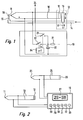
- a thermal circuit 10 consists of a thermocouple 11, which is connected to the solenoid coil 12 of a solenoid valve 13 is.
- a combustible gas leading gas line 14 leads to a focal point 15, for example, the focal point of a Stove or a baking oven.
- the solenoid valve 13 is in the Gas line 14 connected, wherein a valve member 16 for shutting off and opening the gas line 14 is provided.
- the gas line 14 is at rest Valve member 16 by means of a manual actuator 17 pressed into the open position, so that gas to Burner 15 can flow.
- a manual actuator 17 pressed into the open position, so that gas to Burner 15 can flow.
- This is done by means of a lighter ignited, so that a gas flame 18 is formed.
- These Gas flame 18 heats the in a correspondingly close spatial arrangement attached thermocouple 11, so this one Thermostom generated by the solenoid coil 12 of the solenoid valve 13 flows.
- This thermo-current becomes the solenoid valve 13 and the valve member 16 held in the open position, so that the manual actuator 17 is now released can be.
- This drop can by means of a not shown Spring and / or caused by gravity.
- a timer 19 includes a capacitor 20, which with Help of a charging resistor 21 constantly in the charged state is held.
- This capacitor 20 is connected via a Switch 22, for example, a semiconductor switch, parallel connected to the thermocouple 11 and to the solenoid coil 12.
- the switch 22 can via a non-illustrated Time circuit are closed, with off times Ta are programmable. If a switch-off time Ta is reached, so closes the switch 22, causing a temporary compensation current is taken from the capacitor, which in the Thermostrom Vietnamese 10 is fed so that it the thermo-current counteracts. As a result, the solenoid valve 13 drops and the valve member 16 closes the gas line 14.
- Nach subsequently opened switch 22 is the thermo-current of the thermocouple 11 is no longer capable of the solenoid valve 13 to open.
- the capacitor 20 is via another, also timed Switch 23 with a further thermal circuit 24th connected, which is not shown in detail in Figure 1, but only in Figure 2.
- the timer 19 is shown in the outer view. It has next to a display 27 for playback the time and the shutdown times to be set five Timing buttons 28 to 32 for setting the desired Shutdown times for five burners or five thermo circuits and a common time reset button 33, which is for Correction of the shutdown time to be set forwards by a the time presentation keys 28 to 32 is used.
- a display 27 for playback the time and the shutdown times to be set five Timing buttons 28 to 32 for setting the desired Shutdown times for five burners or five thermo circuits and a common time reset button 33, which is for Correction of the shutdown time to be set forwards by a the time presentation keys 28 to 32 is used.
- a common time reset button 33 which is for Correction of the shutdown time to be set forwards by a the time presentation keys 28 to 32 is used.
- time reset buttons 33 or the time adjustment is made according to one of several known Methods for setting switching times.
Landscapes
- Engineering & Computer Science (AREA)
- Chemical & Material Sciences (AREA)
- Combustion & Propulsion (AREA)
- Mechanical Engineering (AREA)
- General Engineering & Computer Science (AREA)
- Control Of Combustion (AREA)
Abstract
Description
Die Erfindung betrifft eine Vorrichtung zum elektrisch gesteuerten Abschalten der Gasflamme einer Brennstelle, der über ein Magnetventil brennbares Gas zuführbar ist, wobei die Magnetspule des Magnetventils von einem Thermoelement gespeist wird und das Magnetventil bei durch die Gasflamme erhitzten Thermoelement in der Offenstellung gehalten wird.The invention relates to a device for electrically controlled Turning off the gas flame of a burner, the over a solenoid valve combustible gas is supplied, wherein the Solenoid of the solenoid valve powered by a thermocouple and the solenoid valve is heated by the gas flame Thermocouple is held in the open position.
Gasventile mit thermisch elektrischer Sicherheitsfunktion sind bekannt. Zum Einschalten der Gasflamme wird das Ventil manuell durch Drücken geöffnet, wodurch u.a. ein Magnetkreis geschlossen wird. Ein Thermoelement versorgt die Magnetspule mit Strom. Dieses Thermoelement wird von der zu überwachenden Gasflamme beheizt. Nachdem die Flamme ein paar Sekunden das Thermoelement aufgeheizt hat, ist der Thermostrom des Thermoelements genügend hoch, um den Magnetkreis geschlossen zu halten und das Gasventil in der Offenstellung zu halten. Erlischt die Flamme durch überkochendes Gargut, Wind oder dergleichen, sinkt der Thermostrom des Thermoelements ab und das Ventil fällt ab bzw. schließt sich automatisch und bleibt auch in der Schließstellung.Gas valves with thermal electrical safety function are known. To turn on the gas flame, the valve manually opened by pressing, whereby u.a. a magnetic circuit is closed. A thermocouple powers the solenoid with electricity. This thermocouple is to be monitored by the Heated gas flame. After the flame a few seconds the Thermocouple has heated, is the thermo-current of the thermocouple high enough to close the magnetic circuit hold and hold the gas valve in the open position. goes out the flame by overcooking food, wind or the like, the thermo-current of the thermocouple decreases and the Valve drops or closes automatically and remains also in the closed position.
Will man nun eine Zeitschaltfunktion realisieren, so besteht eine bekannte Möglichkeit darin, den Thermostrom des Thermoelements über ein Relais zu führen. Zum Ausschalten der Gasflamme wird der Thermostrom durch Öffnen des Relaiskontaktes unterbrochen und das Gasventil schließt. Nachteilig an dieser bekannten Anordnung sind die zusätzlichen Übergangswiderstände und Restspannungen, welche in den Thermostromkreis durch die Verdrahtung und die Schaltuhr gebracht werden. Diese "Verlustspannungen" müssen durch eine höhere Thermospannung ausgeglichen werden, die jedoch erst nach einer längeren Aufheizzeit erreicht wird. Dies hat zur Folge, dass das Ventil länger manuell in der Offenstellung gehalten werden muss, was das System für den täglichen Gebrauch wenig attraktiv macht. Zusätzlich leidet die Funktionssicherheit des Systems durch Verschmutzungen der Relaiskontakte. Verschmutzungen verhindern auch das dauerhafte Offenhalten des Ventils.If you want to realize a timer function, then there is a known possibility therein, the thermo-current of the thermocouple via a relay. To switch off the gas flame the thermal current is opened by opening the relay contact interrupted and the gas valve closes. A disadvantage of this known arrangement, the additional contact resistance and residual stresses, which in the thermal circuit through the wiring and the timer are brought. These "Loss voltages" must be due to a higher thermoelectric voltage be compensated, but only after a long heat-up is reached. As a result, the valve longer manually held in the open position, what makes the system less attractive for everyday use. In addition, the reliability of the system suffers Dirt on the relay contacts. Prevent contamination also the permanent keeping open of the valve.
Eine Aufgabe der vorliegenden Erfindung besteht darin, eine Vorrichtung zum elektrisch gesteuerten Abschalten der Gasflamme einer Brennstelle zu schaffen, die ohne ein Relais bzw. ohne mechanisch bewegte Teile auskommt.An object of the present invention is to provide a Device for the electrically controlled switching off of the gas flame to create a combustion station without a relay or without mechanically moving parts.
Diese Aufgabe wird erfindungsgemäß dadurch gelöst, dass eine Schalteinrichtung zum Einspeisen eines ein abfallendes Magnetventils in die Schließstellung bewirkenden Kompensationsstroms in den Thermostromkreis der mit dem Thermoelement verbundenen Magnetspule vorgesehen ist.This object is achieved in that a Switching device for feeding a sloping solenoid valve in the closed position causing compensation current in the thermal circuit of the thermocouple connected Magnet coil is provided.
Die Vorteile der erfindungsgemäßen Lösung bestehen insbesondere darin, dass der sensible Thermostromkreis zum Abschalten nicht unterbrochen wird und dass keine zu Verschmutzungen neigenden mechanisch bewegbaren Teile erforderlich sind. Bei der erfindungsgemäße Lösung einer Abschaltung mittels eines Kompensationsstroms wird eine technisch und elektrisch unkritische Parallelverbindung zum Thermokreis in der Nähe des Magnetventils geschaffen.The advantages of the solution according to the invention are in particular in that the sensitive thermostatic circuit turns off is not interrupted and that no too dirty tilting mechanically movable parts are required. at the inventive solution of a shutdown by means of a Compensation current becomes technically and electrically uncritical Parallel connection to the thermocircle near the Solenoid valve created.
Durch die in den Unteransprüchen aufgeführten Maßnahmen sind vorteilhafte Weiterbildungen und Verbesserungen der im Anspruch 1 angegebenen Vorrichtung möglich.By the measures listed in the dependent claims are advantageous developments and improvements in the claim 1 specified device possible.
In vorteilhafter Weise ist ein den Kompensationsstrom liefernder Speicherkondensator vorgesehen. Da der Kompensationsstrom nur während des Bruchteils einer Sekunde fließen muss, um den Magnetkreis abfallen zu lassen, bildet ein Kondensator eine kostengünstige und wesentlich einfachere Lösung beispielsweise gegenüber einem Netzteil.Advantageously, a compensating current delivering Storage capacitor provided. Because the compensation current only has to flow during the fraction of a second, to drop the magnetic circuit forms a capacitor a cost-effective and much simpler solution, for example opposite a power supply.
Der Speicherkondensator ist über die Schalteinrichtung mit dem Thermostromkreis verbunden und kann auch bei mehreren Thermostromkreisen über mehrere Schalteinrichtungen mit einer entsprechenden Zahl von Thermostromkreisen verbunden sein.The storage capacitor is via the switching device with connected to the thermal circuit and can also be used at several Thermostromkreisreisen over several switching devices with a corresponding number of Thermostromkreisen be connected.
Der Speicherkondensator ist zweckmäßigerweise mit einer Ladeeinrichtung, insbesondere einem Ladewiderstand verbunden sein, der dafür sorgt, dass der Speicherkondensator ständig geladen ist.The storage capacitor is expediently with a charging device, in particular connected to a charging resistor be who ensures that the storage capacitor constantly loaded.
Die Schalteinrichtung ist vorzugsweise als elektrisch steuerbarer Schalter, insbesondere Halbleiterschalter ausgebildet.The switching device is preferably as electrically controllable Switch, in particular semiconductor switch formed.
In vorteilhafter Weise ist die Schalteinrichtung durch eine Zeitschaltuhr steuerbar, um Abschaltzeiten programmieren zu können. Diese Zeitschaltuhr kann bei Bedarf mehrere voneinander unabhängige Zeitprogramme zum Schalten mehrerer Schalteinrichtungen für mehrere Brennstellen aufweisen.Advantageously, the switching device is characterized by a Timer can be controlled to program shutdown times can. This timer can be several if necessary independent time programs for switching a plurality of switching devices have for several burners.
Die Zeitschaltuhr kann auch eine Sicherheitseinrichtung zum Ausschalten aller Gasflammen nach einer vorgebbaren Maximalzeit von beispielsweise 3 Stunden besitzen. Die Zeit wird dabei so gewählt, dass sie länger ist als eine typische Brenndauer, beispielsweise eines Gasherdes ist. Nach Ablauf der Sicherheitszeit werden alle Gasflammen sicherheitshalber abgeschaltet.The timer can also be a safety device for Switching off all gas flames after a predefinable maximum time for example, have 3 hours. Time will be there chosen so that it is longer than a typical burning time, for example, a gas stove. After expiration of Safety time all gas flames are shut down for safety's sake.
In einer konstruktiv und bedienungsmäßig einfachen und günstigen Ausgestaltung besitzt die Zeitschaltuhr eine der Zahl der Brennstellen entsprechende Zahl von Zeitvorstelltasten und eine gemeinsame Zeitrückstelltaste. Hierdurch wird die Zahl der Bedienelemente auf das Notwendigste beschränkt.In a constructive and easy to use and affordable Design has the timer one of the number number of time presets corresponding to the number of burners and a common time reset button. This will be the Number of controls limited to the bare essentials.
Ein Ausführungsbeispiel der Erfindung ist in der Zeichnung dargestellt und in der nachfolgenden Beschreibung näher erläutert. Es zeigen:
- Figur 1
- eine schematische schaltungsmäßige Darstellung der Abschaltvorrichtung mit einer den Kompensationsstrom erzeugenden Zeitschaltuhr und
- Figur 2
- dasselbe Ausführungsbeispiel mit zwei Thermostromkreisen, wobei die Zeitschaltuhr in der Außenansicht dargestellt ist.
- FIG. 1
- a schematic circuit diagram of the shutdown device with a compensation current generating timer and
- FIG. 2
- the same embodiment with two Thermostromkreisen, the timer is shown in the outer view.
Bei dem in den Figuren 1 und 2 dargestellten Ausführungsbeispiel
besteht ein Thermostromkreis 10 aus einem Thermoelement
11, das mit der Magnetspule 12 eines Magnetventils 13 verbunden
ist. Eine brennbares Gas führende Gasleitung 14 führt zu
einer Brennstelle 15, beispielsweise die Brennstelle eines
Herdes oder eines Backofens. Das Magnetventil 13 ist in die
Gasleitung 14 geschaltet, wobei ein Ventilglied 16 zum Absperren
und Öffnen der Gasleitung 14 vorgesehen ist.In the embodiment shown in Figures 1 and 2
a
Zum Anzünden wird das im Ruhezustand die Gasleitung 14 abschließende
Ventilglied 16 mittels eines manuellen Betätigungsglieds
17 in die Offenstellung gedrückt, so dass Gas zur
Brennstelle 15 strömen kann. Dieses wird mittels eines Anzünders
angezündet, so dass eine Gasflamme 18 entsteht. Diese
Gasflamme 18 erhitzt das in entsprechend naher räumlicher Anordnung
angebrachte Thermoelement 11, so dass dieses einen
Thermostrom erzeugt, der durch die Magnetspule 12 des Magnetventils
13 fließt. Durch diesen Thermostrom wird das Magnetventil
13 bzw. das Ventilglied 16 in der Offenstellung gehalten,
so dass das manuelle Betätigungsglied 17 nunmehr losgelassen
werden kann. Erlischt die Gasflamme 18 durch irgendwelche
Einwirkungen, so kühlt sich das Thermoelement 11 ab,
und der sich verringernde Thermostrom kann das Ventilglied 16
nicht mehr in seiner Offenstellung halten, so dass dieses in
die Schließstellung zurückfällt und die weitere Gaszufuhr
sperrt. Dieses Abfallen kann mittels einer nicht dargestellten
Feder und/oder durch Schwerkraft bewirkt werden.For lighting, the gas line 14 is at rest
Valve
Eine Zeitschaltuhr 19 enthält einen Kondensator 20, der mit
Hilfe eines Ladewiderstandes 21 ständig im aufgeladenen Zustand
gehalten wird. Dieser Kondensator 20 ist über einen
Schalter 22, beispielsweise einen Halbleiterschalter, parallel
zum Thermoelement 11 bzw. zur Magnetspule 12 geschaltet.
Der Schalter 22 kann über einen nicht näher dargestellten
Zeitschaltkreis geschlossen werden, wobei Ausschaltzeiten Ta
einprogrammierbar sind. Ist eine Ausschaltzeit Ta erreicht,
so schließt der Schalter 22, wodurch kurzzeitig ein Kompensationsstrom
dem Kondensator entnommen wird, der in den Thermostromkreis
10 derart eingespeist wird, dass er dem Thermostrom
entgegen wirkt. Hierdurch fällt das Magnetventil 13 ab
und das Ventilglied 16 verschließt die Gasleitung 14. Nach
anschließend wieder geöffnetem Schalter 22 ist der Thermostrom
des Thermoelements 11 nicht mehr in der Lage, das Magnetventil
13 zu öffnen.A
Der Kondensator 20 ist über einen weiteren, ebenfalls zeitgesteuerten
Schalter 23 mit einem weiteren Thermostromkreis 24
verbunden, der jedoch in Figur 1 nicht näher dargestellt ist,
sondern lediglich in Figur 2. Auch dieser besteht wiederum
aus einem Thermoelement 25 und der Magnetspule 26 eines im
Übrigen nicht dargestellten Magnetventils in der Gasleitung
für eine weitere, ebenfalls nicht näher dargestellte Brennstelle.The
Entsprechend können an den Kondensator 20 noch weitere Thermostromkreise
für weitere Brennstellen angeschlossen werden,
wobei die Magnetventile dennoch im Sekundenbereich nacheinander
abgeschaltet werden können. Accordingly, to the
In Figur 2 ist die Zeitschaltuhr 19 in der Außenansicht dargestellt.
Sie besitzt neben einem Display 27 für die Wiedergabe
der Uhrzeit und der einzustellenden Abschaltzeiten fünf
Zeitvorstelltasten 28 bis 32 zum Einstellen der gewünschten
Abschaltzeiten für fünf Brennstellen bzw. fünf Thermostromkreise
sowie eine gemeinsame Zeitrückstelltaste 33, die zur
Korrektur der vorwärts einzustellenden Abschaltzeit durch eine
der Zeitvorstelltasten 28 bis 32 dient. Selbstverständlich
könnte man auch mehrere Zeitrückstelltasten 33 vorsehen oder
die Zeiteinstellung erfolgt gemäß einer von mehreren bekannten
Methoden zur Einstellung von Schaltuhrenzeiten.In Figure 2, the
In der Zeitschaltuhr ist noch eine Sicherheitsabschaltung
vorgesehen, durch die nach Brenndauern, die über übliche typische
Brenndauern von z.B. drei Stunden hinausgehen, alle
Gasflammen sicherheitshalber abgeschaltet werden. Dies kann
mittels eines zusätzlichen Zeitglieds erfolgen, durch das
nach der Sicherheitszeit alle Schalter 22, 23 geschlossen
werden. Da die Zeitsteuerung üblicherweise in einem Microcontroller
34 erfolgt, braucht dessen Programm lediglich diese
Abschaltzeit enthalten, nach Ablauf derer entsprechende
Steuerausgänge alle Schalter 22, 23 geschlossen werden.There is still a safety shutdown in the timer
provided, by the after burning periods, over the usual typical
Burning times of e.g. go out for three hours, all
Gas flames are shut off for safety's sake. This can
by means of an additional timer, by the
After the safety time all
Claims (9)
Priority Applications (2)
| Application Number | Priority Date | Filing Date | Title |
|---|---|---|---|
| SI200432175T SI1505344T1 (en) | 2003-08-02 | 2004-05-26 | electric activated device to shut off the gas flame of one of several cooking units |
| PL04012387T PL1505344T3 (en) | 2003-08-02 | 2004-05-26 | electric activated device to shut off the gas flame of one of several cooking units |
Applications Claiming Priority (2)
| Application Number | Priority Date | Filing Date | Title |
|---|---|---|---|
| DE10335465A DE10335465A1 (en) | 2003-08-02 | 2003-08-02 | Device for electrically controlled switching off the gas flame of a combustion station |
| DE10335465 | 2003-08-02 |
Publications (3)
| Publication Number | Publication Date |
|---|---|
| EP1505344A2 true EP1505344A2 (en) | 2005-02-09 |
| EP1505344A3 EP1505344A3 (en) | 2010-06-02 |
| EP1505344B1 EP1505344B1 (en) | 2014-04-30 |
Family
ID=33547053
Family Applications (1)
| Application Number | Title | Priority Date | Filing Date |
|---|---|---|---|
| EP04012387.9A Expired - Lifetime EP1505344B1 (en) | 2003-08-02 | 2004-05-26 | electric activated device to shut off the gas flame of one of several cooking units |
Country Status (5)
| Country | Link |
|---|---|
| EP (1) | EP1505344B1 (en) |
| DE (1) | DE10335465A1 (en) |
| ES (1) | ES2485843T3 (en) |
| PL (1) | PL1505344T3 (en) |
| SI (1) | SI1505344T1 (en) |
Cited By (2)
| Publication number | Priority date | Publication date | Assignee | Title |
|---|---|---|---|---|
| NL2004917C2 (en) * | 2010-06-18 | 2011-12-20 | Intell Properties B V | Device and method for electrically controlled turning off of a gas flame of a gas hob. |
| IT201700017422A1 (en) * | 2017-02-16 | 2018-08-16 | Vanni Gallocchio | SAFETY DEVICE FOR GAS BURNERS OF STOVES, KITCHENS AND COOKTOPS IN GENERAL |
Citations (2)
| Publication number | Priority date | Publication date | Assignee | Title |
|---|---|---|---|---|
| JPS62293016A (en) | 1986-06-11 | 1987-12-19 | Matsushita Electric Ind Co Ltd | Gas appliance with time limit device |
| EP1113227A2 (en) | 1999-12-16 | 2001-07-04 | Whirlpool Corporation | Device for obtaining rapid ignition of a cooking hob gas burner fed via a gas pipe provided with a solenoid safety valve |
Family Cites Families (7)
| Publication number | Priority date | Publication date | Assignee | Title |
|---|---|---|---|---|
| GB1098811A (en) * | 1963-07-19 | 1968-01-10 | Seemark Switches Ltd | Improvements in timers or safety cut-outs for fuel-burning appliances |
| DE1233793B (en) * | 1964-05-27 | 1967-02-09 | Krefft Aktien Ges W | Device for securing gas burners on gas appliances |
| JPH0292450A (en) * | 1988-09-30 | 1990-04-03 | Nok Corp | Method for removing pattern from forming product and induction heating type pattern removing device |
| IT1283738B1 (en) * | 1996-04-15 | 1998-04-30 | Whirpool Europ S R L | GAS OPERATING APPLIANCE FOR HEATING AND / OR COOKING FOOD AND SIMILAR |
| JP3693196B2 (en) * | 1996-05-24 | 2005-09-07 | パロマ工業株式会社 | Gas cooker |
| KR100359624B1 (en) * | 2000-02-29 | 2002-11-07 | 최영규 | Open Time Controlable Valve Assembly with Electronic Timer |
| US20020073985A1 (en) * | 2000-12-18 | 2002-06-20 | Bsh Home Appliances Corporation | Pulsed sequence burner control with valve |
-
2003
- 2003-08-02 DE DE10335465A patent/DE10335465A1/en not_active Ceased
-
2004
- 2004-05-26 EP EP04012387.9A patent/EP1505344B1/en not_active Expired - Lifetime
- 2004-05-26 ES ES04012387.9T patent/ES2485843T3/en not_active Expired - Lifetime
- 2004-05-26 SI SI200432175T patent/SI1505344T1/en unknown
- 2004-05-26 PL PL04012387T patent/PL1505344T3/en unknown
Patent Citations (2)
| Publication number | Priority date | Publication date | Assignee | Title |
|---|---|---|---|---|
| JPS62293016A (en) | 1986-06-11 | 1987-12-19 | Matsushita Electric Ind Co Ltd | Gas appliance with time limit device |
| EP1113227A2 (en) | 1999-12-16 | 2001-07-04 | Whirlpool Corporation | Device for obtaining rapid ignition of a cooking hob gas burner fed via a gas pipe provided with a solenoid safety valve |
Cited By (3)
| Publication number | Priority date | Publication date | Assignee | Title |
|---|---|---|---|---|
| NL2004917C2 (en) * | 2010-06-18 | 2011-12-20 | Intell Properties B V | Device and method for electrically controlled turning off of a gas flame of a gas hob. |
| IT201700017422A1 (en) * | 2017-02-16 | 2018-08-16 | Vanni Gallocchio | SAFETY DEVICE FOR GAS BURNERS OF STOVES, KITCHENS AND COOKTOPS IN GENERAL |
| WO2018150349A1 (en) * | 2017-02-16 | 2018-08-23 | Fioranzato Diego | Safety device for gas burners of stoves, cookers and hobs in general |
Also Published As
| Publication number | Publication date |
|---|---|
| EP1505344B1 (en) | 2014-04-30 |
| EP1505344A3 (en) | 2010-06-02 |
| DE10335465A1 (en) | 2005-03-03 |
| PL1505344T3 (en) | 2014-09-30 |
| SI1505344T1 (en) | 2014-08-29 |
| ES2485843T3 (en) | 2014-08-14 |
Similar Documents
| Publication | Publication Date | Title |
|---|---|---|
| DE19500263C2 (en) | Cooking apparatus with at least one covered hob and a radiant burner unit | |
| WO2007020178A1 (en) | Timer for a gas cooking hob | |
| DE2839012A1 (en) | ARRANGEMENT IN THE CASE OF A GAS FIRED APPARATUS, IN PARTICULAR ABSORPTION COOLING DEVICE | |
| EP1505344A2 (en) | Electric activated device to shut off the gas flame of a cooking unit | |
| DE2943333A1 (en) | AUTOMATIC GAS BURNER EQUIPMENT | |
| EP1592922B1 (en) | Method and arrangement for igniting a gas flow | |
| DE2917584C2 (en) | ||
| DE102006032020A1 (en) | Valve unit for e.g. domestic gas fire, is based on actuator-controlled rotary valve plug with cams operating position-sensing switch connected to controller | |
| DE19723653A1 (en) | Safety disconnector e.g for commercial and domestic gas-burning apparatus | |
| EP1592923B1 (en) | Method and circuit for igniting a gas flow | |
| DE4238816C1 (en) | Gas stove with a ceramic hob | |
| DE3641047C2 (en) | ||
| DE202018006456U1 (en) | Device for regulating the gas supply | |
| DE10217008A1 (en) | Method for operating a gas-operated cooking or roasting device and device for carrying out the method | |
| DE2222259A1 (en) | CONTROL CIRCUIT FOR OIL AND GAS BURNERS | |
| DE60007933T2 (en) | Control device for opening a safety valve of the gas flow of a burner | |
| EP1462725B1 (en) | Cooking device, in particular backing oven with at least a gas burner | |
| DE896976C (en) | Regulating arrangement for electric heaters | |
| DE2819906A1 (en) | THERMOELECTRIC SHUT-OFF CONTROL DEVICE | |
| AT208556B (en) | Safety and ignition device for a burner | |
| DE903201C (en) | Safety system for gas-heated devices | |
| DE578232C (en) | Electrical control device for oil firing systems | |
| EP3877698A1 (en) | Device for regulating a supply of gas | |
| DE1109624B (en) | Safety and ignition device for a burner | |
| DE1233793B (en) | Device for securing gas burners on gas appliances |
Legal Events
| Date | Code | Title | Description |
|---|---|---|---|
| PUAI | Public reference made under article 153(3) epc to a published international application that has entered the european phase |
Free format text: ORIGINAL CODE: 0009012 |
|
| AK | Designated contracting states |
Kind code of ref document: A2 Designated state(s): AT BE BG CH CY CZ DE DK EE ES FI FR GB GR HU IE IT LI LU MC NL PL PT RO SE SI SK TR |
|
| AX | Request for extension of the european patent |
Extension state: AL HR LT LV MK |
|
| PUAL | Search report despatched |
Free format text: ORIGINAL CODE: 0009013 |
|
| AK | Designated contracting states |
Kind code of ref document: A3 Designated state(s): AT BE BG CH CY CZ DE DK EE ES FI FR GB GR HU IE IT LI LU MC NL PL PT RO SE SI SK TR |
|
| AX | Request for extension of the european patent |
Extension state: AL HR LT LV MK |
|
| RIC1 | Information provided on ipc code assigned before grant |
Ipc: F23N 5/20 20060101ALI20100423BHEP Ipc: F23N 5/24 20060101ALI20100423BHEP Ipc: F23N 5/10 20060101AFI20041104BHEP |
|
| 17P | Request for examination filed |
Effective date: 20100612 |
|
| AKX | Designation fees paid |
Designated state(s): AT BE BG CH CY CZ DE DK EE ES FI FR GB GR HU IE IT LI LU MC NL PL PT RO SE SI SK TR |
|
| 17Q | First examination report despatched |
Effective date: 20110524 |
|
| GRAP | Despatch of communication of intention to grant a patent |
Free format text: ORIGINAL CODE: EPIDOSNIGR1 |
|
| INTG | Intention to grant announced |
Effective date: 20131205 |
|
| GRAS | Grant fee paid |
Free format text: ORIGINAL CODE: EPIDOSNIGR3 |
|
| GRAA | (expected) grant |
Free format text: ORIGINAL CODE: 0009210 |
|
| AK | Designated contracting states |
Kind code of ref document: B1 Designated state(s): AT BE BG CH CY CZ DE DK EE ES FI FR GB GR HU IE IT LI LU MC NL PL PT RO SE SI SK TR |
|
| REG | Reference to a national code |
Ref country code: CH Ref legal event code: EP Ref country code: GB Ref legal event code: FG4D Free format text: NOT ENGLISH |
|
| REG | Reference to a national code |
Ref country code: AT Ref legal event code: REF Ref document number: 665398 Country of ref document: AT Kind code of ref document: T Effective date: 20140515 |
|
| REG | Reference to a national code |
Ref country code: IE Ref legal event code: FG4D Free format text: LANGUAGE OF EP DOCUMENT: GERMAN |
|
| REG | Reference to a national code |
Ref country code: DE Ref legal event code: R096 Ref document number: 502004014600 Country of ref document: DE Effective date: 20140612 |
|
| REG | Reference to a national code |
Ref country code: RO Ref legal event code: EPE |
|
| REG | Reference to a national code |
Ref country code: ES Ref legal event code: FG2A Ref document number: 2485843 Country of ref document: ES Kind code of ref document: T3 Effective date: 20140814 |
|
| REG | Reference to a national code |
Ref country code: PL Ref legal event code: T3 |
|
| REG | Reference to a national code |
Ref country code: NL Ref legal event code: VDEP Effective date: 20140430 |
|
| PG25 | Lapsed in a contracting state [announced via postgrant information from national office to epo] |
Ref country code: GR Free format text: LAPSE BECAUSE OF FAILURE TO SUBMIT A TRANSLATION OF THE DESCRIPTION OR TO PAY THE FEE WITHIN THE PRESCRIBED TIME-LIMIT Effective date: 20140731 Ref country code: NL Free format text: LAPSE BECAUSE OF FAILURE TO SUBMIT A TRANSLATION OF THE DESCRIPTION OR TO PAY THE FEE WITHIN THE PRESCRIBED TIME-LIMIT Effective date: 20140430 Ref country code: FI Free format text: LAPSE BECAUSE OF FAILURE TO SUBMIT A TRANSLATION OF THE DESCRIPTION OR TO PAY THE FEE WITHIN THE PRESCRIBED TIME-LIMIT Effective date: 20140430 Ref country code: CY Free format text: LAPSE BECAUSE OF FAILURE TO SUBMIT A TRANSLATION OF THE DESCRIPTION OR TO PAY THE FEE WITHIN THE PRESCRIBED TIME-LIMIT Effective date: 20140430 Ref country code: BG Free format text: LAPSE BECAUSE OF FAILURE TO SUBMIT A TRANSLATION OF THE DESCRIPTION OR TO PAY THE FEE WITHIN THE PRESCRIBED TIME-LIMIT Effective date: 20140730 |
|
| PG25 | Lapsed in a contracting state [announced via postgrant information from national office to epo] |
Ref country code: SE Free format text: LAPSE BECAUSE OF FAILURE TO SUBMIT A TRANSLATION OF THE DESCRIPTION OR TO PAY THE FEE WITHIN THE PRESCRIBED TIME-LIMIT Effective date: 20140430 |
|
| PG25 | Lapsed in a contracting state [announced via postgrant information from national office to epo] |
Ref country code: PT Free format text: LAPSE BECAUSE OF FAILURE TO SUBMIT A TRANSLATION OF THE DESCRIPTION OR TO PAY THE FEE WITHIN THE PRESCRIBED TIME-LIMIT Effective date: 20140901 |
|
| REG | Reference to a national code |
Ref country code: CH Ref legal event code: PL |
|
| PG25 | Lapsed in a contracting state [announced via postgrant information from national office to epo] |
Ref country code: CH Free format text: LAPSE BECAUSE OF NON-PAYMENT OF DUE FEES Effective date: 20140531 Ref country code: MC Free format text: LAPSE BECAUSE OF FAILURE TO SUBMIT A TRANSLATION OF THE DESCRIPTION OR TO PAY THE FEE WITHIN THE PRESCRIBED TIME-LIMIT Effective date: 20140430 Ref country code: CZ Free format text: LAPSE BECAUSE OF FAILURE TO SUBMIT A TRANSLATION OF THE DESCRIPTION OR TO PAY THE FEE WITHIN THE PRESCRIBED TIME-LIMIT Effective date: 20140430 Ref country code: LI Free format text: LAPSE BECAUSE OF NON-PAYMENT OF DUE FEES Effective date: 20140531 Ref country code: DK Free format text: LAPSE BECAUSE OF FAILURE TO SUBMIT A TRANSLATION OF THE DESCRIPTION OR TO PAY THE FEE WITHIN THE PRESCRIBED TIME-LIMIT Effective date: 20140430 Ref country code: EE Free format text: LAPSE BECAUSE OF FAILURE TO SUBMIT A TRANSLATION OF THE DESCRIPTION OR TO PAY THE FEE WITHIN THE PRESCRIBED TIME-LIMIT Effective date: 20140430 Ref country code: SK Free format text: LAPSE BECAUSE OF FAILURE TO SUBMIT A TRANSLATION OF THE DESCRIPTION OR TO PAY THE FEE WITHIN THE PRESCRIBED TIME-LIMIT Effective date: 20140430 |
|
| REG | Reference to a national code |
Ref country code: DE Ref legal event code: R097 Ref document number: 502004014600 Country of ref document: DE |
|
| REG | Reference to a national code |
Ref country code: IE Ref legal event code: MM4A |
|
| PLBE | No opposition filed within time limit |
Free format text: ORIGINAL CODE: 0009261 |
|
| STAA | Information on the status of an ep patent application or granted ep patent |
Free format text: STATUS: NO OPPOSITION FILED WITHIN TIME LIMIT |
|
| GBPC | Gb: european patent ceased through non-payment of renewal fee |
Effective date: 20140730 |
|
| REG | Reference to a national code |
Ref country code: FR Ref legal event code: ST Effective date: 20150302 |
|
| 26N | No opposition filed |
Effective date: 20150202 |
|
| PG25 | Lapsed in a contracting state [announced via postgrant information from national office to epo] |
Ref country code: IE Free format text: LAPSE BECAUSE OF NON-PAYMENT OF DUE FEES Effective date: 20140526 |
|
| REG | Reference to a national code |
Ref country code: DE Ref legal event code: R097 Ref document number: 502004014600 Country of ref document: DE Effective date: 20150202 |
|
| PG25 | Lapsed in a contracting state [announced via postgrant information from national office to epo] |
Ref country code: GB Free format text: LAPSE BECAUSE OF NON-PAYMENT OF DUE FEES Effective date: 20140730 Ref country code: FR Free format text: LAPSE BECAUSE OF NON-PAYMENT OF DUE FEES Effective date: 20140630 |
|
| REG | Reference to a national code |
Ref country code: AT Ref legal event code: MM01 Ref document number: 665398 Country of ref document: AT Kind code of ref document: T Effective date: 20140526 |
|
| PG25 | Lapsed in a contracting state [announced via postgrant information from national office to epo] |
Ref country code: AT Free format text: LAPSE BECAUSE OF NON-PAYMENT OF DUE FEES Effective date: 20140526 |
|
| PG25 | Lapsed in a contracting state [announced via postgrant information from national office to epo] |
Ref country code: LU Free format text: LAPSE BECAUSE OF NON-PAYMENT OF DUE FEES Effective date: 20140526 Ref country code: BE Free format text: LAPSE BECAUSE OF FAILURE TO SUBMIT A TRANSLATION OF THE DESCRIPTION OR TO PAY THE FEE WITHIN THE PRESCRIBED TIME-LIMIT Effective date: 20140531 Ref country code: HU Free format text: LAPSE BECAUSE OF FAILURE TO SUBMIT A TRANSLATION OF THE DESCRIPTION OR TO PAY THE FEE WITHIN THE PRESCRIBED TIME-LIMIT; INVALID AB INITIO Effective date: 20040526 |
|
| REG | Reference to a national code |
Ref country code: SI Ref legal event code: SP73 Owner name: ROBERTSHAW CONTROLS COMPANY; US Effective date: 20181018 |
|
| PGFP | Annual fee paid to national office [announced via postgrant information from national office to epo] |
Ref country code: RO Payment date: 20230623 Year of fee payment: 20 Ref country code: IT Payment date: 20230612 Year of fee payment: 20 Ref country code: DE Payment date: 20230613 Year of fee payment: 20 |
|
| PGFP | Annual fee paid to national office [announced via postgrant information from national office to epo] |
Ref country code: TR Payment date: 20230616 Year of fee payment: 20 Ref country code: SI Payment date: 20230613 Year of fee payment: 20 Ref country code: PL Payment date: 20230613 Year of fee payment: 20 |
|
| PGFP | Annual fee paid to national office [announced via postgrant information from national office to epo] |
Ref country code: ES Payment date: 20230630 Year of fee payment: 20 |