EP1505293A1 - Kraftstoffversorgungsanlage und -verfahren für eine direkteinspritzende Brennkraftmaschine - Google Patents
Kraftstoffversorgungsanlage und -verfahren für eine direkteinspritzende Brennkraftmaschine Download PDFInfo
- Publication number
- EP1505293A1 EP1505293A1 EP04018633A EP04018633A EP1505293A1 EP 1505293 A1 EP1505293 A1 EP 1505293A1 EP 04018633 A EP04018633 A EP 04018633A EP 04018633 A EP04018633 A EP 04018633A EP 1505293 A1 EP1505293 A1 EP 1505293A1
- Authority
- EP
- European Patent Office
- Prior art keywords
- fuel
- fuel injector
- injector
- engine
- primary
- Prior art date
- Legal status (The legal status is an assumption and is not a legal conclusion. Google has not performed a legal analysis and makes no representation as to the accuracy of the status listed.)
- Withdrawn
Links
Images


Classifications
-
- F—MECHANICAL ENGINEERING; LIGHTING; HEATING; WEAPONS; BLASTING
- F02—COMBUSTION ENGINES; HOT-GAS OR COMBUSTION-PRODUCT ENGINE PLANTS
- F02M—SUPPLYING COMBUSTION ENGINES IN GENERAL WITH COMBUSTIBLE MIXTURES OR CONSTITUENTS THEREOF
- F02M69/00—Low-pressure fuel-injection apparatus ; Apparatus with both continuous and intermittent injection; Apparatus injecting different types of fuel
- F02M69/04—Injectors peculiar thereto
- F02M69/042—Positioning of injectors with respect to engine, e.g. in the air intake conduit
- F02M69/046—Positioning of injectors with respect to engine, e.g. in the air intake conduit for injecting into both the combustion chamber and the intake conduit
-
- F—MECHANICAL ENGINEERING; LIGHTING; HEATING; WEAPONS; BLASTING
- F02—COMBUSTION ENGINES; HOT-GAS OR COMBUSTION-PRODUCT ENGINE PLANTS
- F02D—CONTROLLING COMBUSTION ENGINES
- F02D41/00—Electrical control of supply of combustible mixture or its constituents
- F02D41/0002—Controlling intake air
- F02D41/0007—Controlling intake air for control of turbo-charged or super-charged engines
-
- F—MECHANICAL ENGINEERING; LIGHTING; HEATING; WEAPONS; BLASTING
- F02—COMBUSTION ENGINES; HOT-GAS OR COMBUSTION-PRODUCT ENGINE PLANTS
- F02D—CONTROLLING COMBUSTION ENGINES
- F02D41/00—Electrical control of supply of combustible mixture or its constituents
- F02D41/30—Controlling fuel injection
- F02D41/3094—Controlling fuel injection the fuel injection being effected by at least two different injectors, e.g. one in the intake manifold and one in the cylinder
-
- F—MECHANICAL ENGINEERING; LIGHTING; HEATING; WEAPONS; BLASTING
- F02—COMBUSTION ENGINES; HOT-GAS OR COMBUSTION-PRODUCT ENGINE PLANTS
- F02M—SUPPLYING COMBUSTION ENGINES IN GENERAL WITH COMBUSTIBLE MIXTURES OR CONSTITUENTS THEREOF
- F02M31/00—Apparatus for thermally treating combustion-air, fuel, or fuel-air mixture
- F02M31/02—Apparatus for thermally treating combustion-air, fuel, or fuel-air mixture for heating
- F02M31/12—Apparatus for thermally treating combustion-air, fuel, or fuel-air mixture for heating electrically
- F02M31/135—Fuel-air mixture
-
- F—MECHANICAL ENGINEERING; LIGHTING; HEATING; WEAPONS; BLASTING
- F02—COMBUSTION ENGINES; HOT-GAS OR COMBUSTION-PRODUCT ENGINE PLANTS
- F02M—SUPPLYING COMBUSTION ENGINES IN GENERAL WITH COMBUSTIBLE MIXTURES OR CONSTITUENTS THEREOF
- F02M45/00—Fuel-injection apparatus characterised by having a cyclic delivery of specific time/pressure or time/quantity relationship
- F02M45/02—Fuel-injection apparatus characterised by having a cyclic delivery of specific time/pressure or time/quantity relationship with each cyclic delivery being separated into two or more parts
-
- F—MECHANICAL ENGINEERING; LIGHTING; HEATING; WEAPONS; BLASTING
- F02—COMBUSTION ENGINES; HOT-GAS OR COMBUSTION-PRODUCT ENGINE PLANTS
- F02M—SUPPLYING COMBUSTION ENGINES IN GENERAL WITH COMBUSTIBLE MIXTURES OR CONSTITUENTS THEREOF
- F02M61/00—Fuel-injectors not provided for in groups F02M39/00 - F02M57/00 or F02M67/00
- F02M61/14—Arrangements of injectors with respect to engines; Mounting of injectors
-
- F—MECHANICAL ENGINEERING; LIGHTING; HEATING; WEAPONS; BLASTING
- F02—COMBUSTION ENGINES; HOT-GAS OR COMBUSTION-PRODUCT ENGINE PLANTS
- F02M—SUPPLYING COMBUSTION ENGINES IN GENERAL WITH COMBUSTIBLE MIXTURES OR CONSTITUENTS THEREOF
- F02M69/00—Low-pressure fuel-injection apparatus ; Apparatus with both continuous and intermittent injection; Apparatus injecting different types of fuel
- F02M69/04—Injectors peculiar thereto
- F02M69/042—Positioning of injectors with respect to engine, e.g. in the air intake conduit
- F02M69/044—Positioning of injectors with respect to engine, e.g. in the air intake conduit for injecting into the intake conduit downstream of an air throttle valve
-
- F—MECHANICAL ENGINEERING; LIGHTING; HEATING; WEAPONS; BLASTING
- F02—COMBUSTION ENGINES; HOT-GAS OR COMBUSTION-PRODUCT ENGINE PLANTS
- F02M—SUPPLYING COMBUSTION ENGINES IN GENERAL WITH COMBUSTIBLE MIXTURES OR CONSTITUENTS THEREOF
- F02M69/00—Low-pressure fuel-injection apparatus ; Apparatus with both continuous and intermittent injection; Apparatus injecting different types of fuel
- F02M69/30—Low-pressure fuel-injection apparatus ; Apparatus with both continuous and intermittent injection; Apparatus injecting different types of fuel characterised by means for facilitating the starting-up or idling of engines or by means for enriching fuel charge, e.g. below operational temperatures or upon high power demand of engines
-
- F—MECHANICAL ENGINEERING; LIGHTING; HEATING; WEAPONS; BLASTING
- F02—COMBUSTION ENGINES; HOT-GAS OR COMBUSTION-PRODUCT ENGINE PLANTS
- F02B—INTERNAL-COMBUSTION PISTON ENGINES; COMBUSTION ENGINES IN GENERAL
- F02B23/00—Other engines characterised by special shape or construction of combustion chambers to improve operation
- F02B23/08—Other engines characterised by special shape or construction of combustion chambers to improve operation with positive ignition
- F02B23/10—Other engines characterised by special shape or construction of combustion chambers to improve operation with positive ignition with separate admission of air and fuel into cylinder
- F02B2023/106—Tumble flow, i.e. the axis of rotation of the main charge flow motion is horizontal
-
- F—MECHANICAL ENGINEERING; LIGHTING; HEATING; WEAPONS; BLASTING
- F02—COMBUSTION ENGINES; HOT-GAS OR COMBUSTION-PRODUCT ENGINE PLANTS
- F02B—INTERNAL-COMBUSTION PISTON ENGINES; COMBUSTION ENGINES IN GENERAL
- F02B75/00—Other engines
- F02B75/12—Other methods of operation
- F02B2075/125—Direct injection in the combustion chamber for spark ignition engines, i.e. not in pre-combustion chamber
-
- F—MECHANICAL ENGINEERING; LIGHTING; HEATING; WEAPONS; BLASTING
- F02—COMBUSTION ENGINES; HOT-GAS OR COMBUSTION-PRODUCT ENGINE PLANTS
- F02B—INTERNAL-COMBUSTION PISTON ENGINES; COMBUSTION ENGINES IN GENERAL
- F02B2275/00—Other engines, components or details, not provided for in other groups of this subclass
- F02B2275/16—Indirect injection
-
- F—MECHANICAL ENGINEERING; LIGHTING; HEATING; WEAPONS; BLASTING
- F02—COMBUSTION ENGINES; HOT-GAS OR COMBUSTION-PRODUCT ENGINE PLANTS
- F02B—INTERNAL-COMBUSTION PISTON ENGINES; COMBUSTION ENGINES IN GENERAL
- F02B29/00—Engines characterised by provision for charging or scavenging not provided for in groups F02B25/00, F02B27/00 or F02B33/00 - F02B39/00; Details thereof
- F02B29/04—Cooling of air intake supply
- F02B29/0406—Layout of the intake air cooling or coolant circuit
-
- F—MECHANICAL ENGINEERING; LIGHTING; HEATING; WEAPONS; BLASTING
- F02—COMBUSTION ENGINES; HOT-GAS OR COMBUSTION-PRODUCT ENGINE PLANTS
- F02B—INTERNAL-COMBUSTION PISTON ENGINES; COMBUSTION ENGINES IN GENERAL
- F02B37/00—Engines characterised by provision of pumps driven at least for part of the time by exhaust
-
- Y—GENERAL TAGGING OF NEW TECHNOLOGICAL DEVELOPMENTS; GENERAL TAGGING OF CROSS-SECTIONAL TECHNOLOGIES SPANNING OVER SEVERAL SECTIONS OF THE IPC; TECHNICAL SUBJECTS COVERED BY FORMER USPC CROSS-REFERENCE ART COLLECTIONS [XRACs] AND DIGESTS
- Y02—TECHNOLOGIES OR APPLICATIONS FOR MITIGATION OR ADAPTATION AGAINST CLIMATE CHANGE
- Y02T—CLIMATE CHANGE MITIGATION TECHNOLOGIES RELATED TO TRANSPORTATION
- Y02T10/00—Road transport of goods or passengers
- Y02T10/10—Internal combustion engine [ICE] based vehicles
- Y02T10/12—Improving ICE efficiencies
Definitions
- the present invention relates to a fuel supply system and a fuel supply method for in-cylinder direct fuel injection engine.
- U.S. Patent Publication No. 5894832 has proposed heating and vaporizing fuel supplied from a fuel injector by a heater installed in an intake passage so as to reduce fuel adhesion onto the intake passage and an intake valve, thereby improving combustion and reducing emissions of hydrocarbon at the time of cold start of an engine particularly.
- Japanese Application Patent Laid-Open Publication No. Hei 11-166421 have proposed, instead of a port injection engine that fuel is injected at an intake port, an in-cylinder direct fuel injection engine that fuel is injected directly into the engine.
- the in-cylinder direct fuel injection engine intends to reduce fuel consumption with aid of stratified combustion as described in the publication.
- a fuel injector installed in the intake port of each cylinder has the following degree of freedom about a period of time in which can inject fuel. That is, the period can be set at the time of at least one of the compression stroke, the expansion stroke, the exhaust stroke, and the intake stroke just before the combustion cycle of the injected fuel.
- a period of time in which a fuel injector installed on each cylinder can inject fuel is limited shorter than that on a port injection engine. That is, only at least one of the intake stroke and the compression stroke.
- the fuel injector for in-cylinder direct fuel injection is required to have higher injection rate and greater dynamic range than the fuel injector for port injection.
- the present invention is to solve the above problems and to provide a fuel supply system and method for in-cylinder direct fuel injection engine that realizes higher output.
- a fuel supply system for in-cylinder direct fuel injection engine of the present invention may comprise a primary fuel injector for injecting fuel directly into a cylinder of an engine; a supercharger for increasing an intake air quantity of the engine; and a secondary fuel injector provided in addition to the primary fuel injector.
- fuel may be supplied using the primary fuel injector and secondary fuel injector together.
- the fuel supply system constructed as above can increase the engine output because the fuel insufficiency can be supplemented by the fuel from the secondary fuel injector.
- an electric heater may be provided on or near to the secondary fuel injector.
- the fuel supplied from the secondary fuel injector can be vaporized easily even while the engine is cold and hence stable combustion can be provided.
- the electric heater may be not energized in an area where the engine load is higher than a specified value, and/or the electric heater may be not energized under a condition where fuel is supplied using the primary fuel injector and the secondary fuel injector. Or the electric heater may be not energized under a condition where fuel is supplied using the primary fuel injector and secondary fuel injector in an area where the engine load is higher than a specified value.
- the electric heater may be energized within a specified period of time after the startup cranking while the catalyst temperature is increasing.
- the heater can be energized conditionally within a specified period of time after the startup cranking while the fuel supplied from the secondary fuel injector needs vaporization.
- the fuel injected from the secondary fuel injector may be used for the combustion contributable to the output of the engine, and the primary fuel injector may be used to inject fuel in a stroke not contributable to the output of the engine.
- the main combustion is carried out by the fuel injected from the secondary fuel injector.
- the fuel from the primary fuel injector may be injected with high degree of freedom at any time from the compression stroke to exhaust stroke so as to react in an exhaust pipe and increase the catalyst temperature quickly.
- the fuel injected from the secondary fuel injector and part of the fuel injected from the primary fuel injector may be used for the combustion contributable to the engine output, and the primary fuel injector may be used to inject fuel in a stroke not contributable to the output of the engine.
- the main combustion is carried out by the fuel injected from the secondary fuel injector and the primary injector.
- the fuel from the primary fuel injector may be injected with high degree of freedom at any time from the compression stroke to exhaust stroke so as to react in an exhaust pipe and increase the catalyst temperature quickly.
- fuel supply to the primary fuel injector may be carried out by a mechanical high-pressure pump, and/or fuel supply to the secondary fuel injector may be carried out by a motor-driven low-pressure pump.
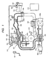
- Fig. 1 shows the overall system construction of a direct injection engine 507.
- Air to be directed into the cylinder 507b (of which air flow is defined as Qc) is taken in from the inlet 502a of an air cleaner 502.
- the air is passed through an air flow sensor 503 as one of the means for measuring the operating condition of the engine, pressurized by a supercharger 534, and then passed through an intercooler 533, passed through a throttle body 505, in which an electronic control throttle valve 505a for controlling the intake air flow rate is installed. And then the air enters a collector 506.
- the airflow sensor outputs a signal showing the intake air flow rate to a control unit 515-engine controller.
- a throttle sensor 504 for sensing the position of the electronic control throttle valve is installed in the throttle body 505. It is one of the means for measuring the operating condition of the engine.
- the throttle sensor also outputs a signal to the control unit 515.
- Air taken into the collector 506 (of which pressure is defined as Pm) is shared into each intake pipe 501 connected to each cylinder 507b of the engine 507 and then directed into the combustion chamber of the cylinder 507b.
- fuel such as gasoline etc. is supplied from a fuel tank 514, pressurized primarily by a fuel pump 510, and regulated to a certain pressure (3 kg/cm 2 for example) by a fuel pressure regulator 512, and then pressurized secondarily to a higher pressure by a fuel pump 511.
- the pressurized fuel is injected into the combustion chamber from an injector 509 provided at each cylinder 507b.
- fuel can also be supplied from a secondary fuel injector 530 located in the downstream of the throttle valve and the supplied fuel can be heated by a heater 531.
- the secondary fuel injector is provided at an intake passage.
- the fuel supplied from the injector 509 which is the primary fuel injector, fuel supplied from the secondary fuel injector 530, or fuel supplied from both is ignited by an ignition plug 508 with an ignition signal of which voltage is made high by an ignition coil 522.
- tumble control valve 532 located on the intake manifold, airflow taken in the cylinder is made fast to generate tumble in the combustion chamber mainly for stabilizing the combustion at the time of stratified combustion.
- a crank angle sensor 516 mounted on the crankshaft of the engine outputs an angle signal POS for sensing the rotation signal (rotation speed), which shows the rotating position of the crankshaft, to the control unit 515.
- An A/F sensor 518 installed in the upstream of the catalyst 520 in the exhaust pipe senses exhaust gas and outputs a sensor signal to the control unit 515.
- Other sensors that output each signal to the control unit include a water temperature sensor 517 for sensing the engine cooling water temperature and an accelerator pedal sensor 521.
- Fig. 2 is the block diagram of the ECU (engine control unit) of the present invention.
- the control unit 515 mainly comprises MPU603, ROM 602, RAM 604 and I/O LSI 601 including A/D converter as illustrated in Fig. 2.
- the control unit 515 inputs signals from various sensors, including a signal from an accelerator position sensor (APS) 521, one of the means for measuring (sensing) the operating condition of the engine and a signal from the fuel pressure sensor 523. And the control unit 515 performs predetermined computation, and outputs results of the computation as various control signals to each injector 509 as the primary fuel injector, the secondary fuel injector 530, the ignition coil 522, and the like so as to control the quantity of fuel supply, ignition timing, and so on.
- APS accelerator position sensor
- the control unit 515 performs predetermined computation, and outputs results of the computation as various control signals to each injector 509 as the primary fuel injector, the secondary fuel injector 530, the ignition coil 522, and the like
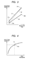
- Fig. 3 shows the injection quantity characteristic of the injector 509, and characteristics of three different injectors are shown.
- the characteristic 30 is defined as the base characteristic.
- Point 30a represents the minimum point where the fuel injection quantity is linear in terms of the injection time.
- Point 30b represents the maximum injection quantity within a specified period of injection time. For an engine of which output needs to be increased with an aid of a supercharger, the maximum injection quantity must be improved.
- the characteristic changes to 31.
- the maximum injection quantity within a specified period of injection time increases to 31b compared to 30b, but the minimum point of linear fuel injection quantity also increases to 31a.
- This characteristic 31b satisfies the requirement for higher engine output but is disadvantageous in view of the stability of idling and controllability of air-fuel ratio.
- a characteristic 32 shown by dotted line is ideal, satisfying both maximum injection quantity and minimum injection quantity, but it is hard to realize as a practical injector.
- Fig. 4 shows the relationship between the fuel pressure and the injection quantity. It shows a characteristic on condition that the fuel pressure is varied in a predetermined period of injection time. As shown by the characteristic 41, the injection quantity can be increased by increasing the fuel pressure. In consideration of the combustion, however, there is a limitation to the increase.
- Fig. 5 is a chart showing the amount of soot to fuel pressure. When the fuel pressure is increased and it exceeds a certain point, the amount of soot increases sharply. It can be understood from Fig. 4 and Fig. 5 that there is a limitation in increasing the fuel pressure to increase the maximum injection quantity.
- Fig. 6 shows the relationship between the total injection quantity and injection quantity from each fuel injector. It shows a characteristic where the injector 509 is used as the primary fuel injector and the secondary fuel injector 530 is used in combination with the primary injector 509.
- the vertical axis represents the total quantity of the primary and secondary injectors, and the horizontal axis represents each injection quantity.
- This chart is based on a condition that an injector having the base characteristic 30 in Fig. 3 is used as the primary fuel injector. Starting from the total injection quantity zero up to the point 30b, each injection quantity 60a is injected only from the primary fuel injector. In an area exceeding the point 30b, the injection quantity 60b is injected from the secondary injector. Owing to the base characteristic 30, the maximum injection quantity 31b shown in Fig. 3 can be achieved by the secondary injector and the primary injector while maintaining the minimum injection quantity 30a shown in Fig. 3.
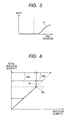
- Fig. 7 shows the relationship between the engine load and the fuel injection quantity.
- the horizontal axis represents the engine load and vertical axis represents the total fuel injection quantity.
- the chart shows that the quantity of the primary fuel injector is constant at the time of exceeding a specified load and the secondary injector flow is increased at that time.
- Fig. 8 shows an air-fuel ratio map, in which an operating range of the secondary fuel injector is shown.
- the air-fuel ratio of an in-cylinder direct fuel injection engine employing the stratified combustion is set in the order of "stratified lean”, “homogeneous lean”, “stoichiometric”, and “rich”, starting from the low load side as shown in Fig. 8.
- the secondary injector is not operated at a load below the dotted line and is operated with the primary injector at a load above the dotted line.
- Fig. 9 is a diagram showing the fuel supply system of in-cylinder direct fuel injection engine, taking into account the relationship between the primary fuel injector and secondary fuel injector.
- the intake airflow sensor 503 and throttle valve 505a are installed in the intake passage 6 of the engine.
- the primary fuel injector 509 is provided at each cylinder.
- the secondary fuel injector 530 is installed in the intake passage in the upstream of the primary fuel injector 509.
- the secondary fuel injector 530 is an air-assist type high-atomization injector, and there is provided an air passage 11 through which air for atomizing the fuel is introduced from the upstream of the throttle valve 505a and supplied to the secondary fuel injector 530.
- the particle size of the injected fuel is atomized to 10 micrometers or so, it flows into the cylinder without adhering on the intake passage. Accordingly, the fuel injected from the secondary fuel injector 530 is atomized to about 10 micrometers so that less fuel adheres on the intake passage.
- a heater 531 is installed in the injection direction of the secondary fuel injector 530.
- the heater may be for example a PTC (positive temperature coefficient) heater that has a self temperature-control function and can keep the temperature constant.
- Current is supplied to the heater 531 from a battery 12 via a heater relay 13.
- Current through the heater is sensed as the terminal voltage of a current detecting resistor 20.
- an idle speed control valve (ISC valve) 10 for controlling the auxiliary airflow is installed in the auxiliary air passage 9 bypassing the throttle valve.
- ISC valve idle speed control valve
- the secondary fuel injector 530 is installed in the intake passage in the upstream of the primary fuel injector 509 in Fig. 1 and Fig. 9, the secondary fuel injector 530 can be installed in the auxiliary air passage 9 bypassing the throttle valve.
- Fig. 10 to Fig. 12 are the timing charts showing the relational operations of the primary fuel injector 509, secondary fuel injector 530 and heater 531.
- Fig. 10 and Fig. 11 show the operation according to prior arts and Fig. 12 shows those according to the present invention.
- Fig. 10 explains the operation of a conventional secondary fuel injector in combination with a heater at the time of engine startup.
- the heater is energized and fuel is injected from the secondary fuel injector for tens of seconds from the cold start of the engine up to the activation of the catalyst, taking into account the power consumption of the heater. Then, the injection from the secondary fuel injector and energization of the heater are terminated and the injection from the primary fuel injector is started.
- Fig. 11 explains the operation of another conventional secondary fuel injector in combination with a heater at the time of engine startup.
- Fig. 11 shows a case where the injection from the secondary fuel injector is started from the beginning of the startup cranking. As soon as the startup cranking is started by a starter, the injection from the secondary fuel injector is begun as shown on (d). In this operation, injection from the primary fuel injector is not employed as shown on (c). In addition, it is assumed that the heater was turned on at a suitable timing before the startup as shown on (b) and so the heater has already been heated to some level.
- Fig. 12 shows a transient state, where the engine is accelerated to move from the stoichiometric condition below the dotted line into the area above it in Fig. 8, and explains the operation of the primary and secondary fuel injectors in that state.
- the starter Since the startup operation has completed, the starter is off. The heater is also off because energization is not necessary provided the engine has warmed up completely.
- the accelerator pedal When the accelerator pedal is first operated by the driver intending to increase the speed, the injection quantity from the primary injector begins increasing from time t1. That from the secondary fuel injector at time t1 is zero.
- the injection quantity from the primary fuel injector reaches 30b equivalent of Fig. 6 during the acceleration, injection from the secondary fuel injector begins.
- Time t2 in Fig. 12 is the beginning of the injection from the secondary fuel injector.
- the acceleration continues on, and the air-fuel ratio finally turns to be rich in this case.
- Fig. 13 is a flowchart of the software to be loaded on the ECU 515 for controlling the secondary fuel injector.
- block 1301 checks the battery voltage, and if the answer is NG, block 1303 prohibits injecting from the secondary fuel injector.
- block 1302 checks for failure of the secondary fuel injector and heater, and if the answer is NG, block 1303 prohibits injecting from the secondary fuel injector. If the answer in both block 1301 and 1302 is OK, the next block permits injecting from the secondary fuel injector.
- block 1305 searches the threshold torque Lth, as shown in Fig. 8, for deciding whether to operate the secondary fuel injector.
- Lth threshold torque
- different values of Lth each corresponding to the engine speed as shown in Fig. 8 are collected as table data and the data are stored in the ROM beforehand.
- Block 1306 compares the current torque T computed by the ECU with the above-mentioned Lth. If the current torque is bigger, the processing proceeds to block 1307 and fuel is injected from the secondary fuel injector. If the current torque is smaller, the processing proceeds to block 1308 and none is injected from the secondary fuel injector. Next, even in case fuel is injected from the secondary fuel injector, if the engine cooling water temperature Tw is higher than a specified value Tlo, the heater is turned off in block 1310. On the contrary, if the engine cooling water temperature Tw is lower than a specified value Tlo, the heater is turned on.
- Fig. 15 shows the same operation in Fig. 14 explained above but in terms of time series.
- the secondary fuel injector 1503 shown in shadow is equivalent to 1402 in Fig. 14.
- the total fuel injection quantity can be varied by varying the flow of the primary fuel injector such as from the primary injector flow 1501 to the primary injector flow 1502, centering around 1401.
- data search in block 1307 in Fig. 13 employs a table of engine speed data shown in Fig. 8.
- An answer, however, can be obtained from the total injection quantity shown in Fig. 6, and even with this technique, a fuel injection system having greater dynamic range can be offered.
- the present invention employing the primary fuel injector and secondary fuel injector, can offer a fuel supply system and method for direct injection engine that realizes higher output as explained herein.
Applications Claiming Priority (2)
| Application Number | Priority Date | Filing Date | Title |
|---|---|---|---|
| JP2003206652A JP2005054615A (ja) | 2003-08-08 | 2003-08-08 | 筒内噴射エンジンの燃料供給システム及び燃料供給方法 |
| JP2003206652 | 2003-08-08 |
Publications (1)
| Publication Number | Publication Date |
|---|---|
| EP1505293A1 true EP1505293A1 (de) | 2005-02-09 |
Family
ID=33549914
Family Applications (1)
| Application Number | Title | Priority Date | Filing Date |
|---|---|---|---|
| EP04018633A Withdrawn EP1505293A1 (de) | 2003-08-08 | 2004-08-05 | Kraftstoffversorgungsanlage und -verfahren für eine direkteinspritzende Brennkraftmaschine |
Country Status (3)
| Country | Link |
|---|---|
| US (1) | US20050066939A1 (de) |
| EP (1) | EP1505293A1 (de) |
| JP (1) | JP2005054615A (de) |
Cited By (5)
| Publication number | Priority date | Publication date | Assignee | Title |
|---|---|---|---|---|
| WO2005106239A1 (en) * | 2004-04-28 | 2005-11-10 | Toyota Jidosha Kabushiki Kaisha | Fuel supply apparatus for internal combustion engine |
| WO2006049230A1 (en) * | 2004-11-02 | 2006-05-11 | Toyota Jidosha Kabushiki Kaisha | Control apparatus for internal combustion engine |
| US7191761B2 (en) * | 2004-11-02 | 2007-03-20 | Toyota Jidosha Kabushiki Kaisha | Control apparatus for internal combustion engine |
| EP1803924A2 (de) * | 2005-12-28 | 2007-07-04 | HONDA MOTOR CO., Ltd. | Brennstoffeinspritzsystem für eine Brennkraftmaschine |
| CN101142395B (zh) * | 2005-03-18 | 2010-04-14 | 丰田自动车株式会社 | 用于内燃机的控制设备 |
Families Citing this family (56)
| Publication number | Priority date | Publication date | Assignee | Title |
|---|---|---|---|---|
| US7080626B2 (en) * | 2003-03-07 | 2006-07-25 | General Motors Corporation | Intake mixture motion and cold start fuel vapor enrichment system |
| JP2006132517A (ja) * | 2004-10-07 | 2006-05-25 | Toyota Motor Corp | 内燃機関の燃料噴射装置および内燃機関の高圧燃料系統の制御装置 |
| JP4475221B2 (ja) * | 2005-03-11 | 2010-06-09 | トヨタ自動車株式会社 | エンジン |
| JP4470773B2 (ja) | 2005-03-18 | 2010-06-02 | トヨタ自動車株式会社 | 内燃機関の制御装置 |
| JP4148233B2 (ja) | 2005-03-29 | 2008-09-10 | トヨタ自動車株式会社 | エンジンの燃料噴射制御装置 |
| DE102005014644A1 (de) * | 2005-03-31 | 2006-10-05 | Daimlerchrysler Ag | Brennstoffzuführsystem für eine Brennkraftmaschine |
| JP4349344B2 (ja) * | 2005-08-23 | 2009-10-21 | トヨタ自動車株式会社 | エンジンの制御装置 |
| US8132555B2 (en) * | 2005-11-30 | 2012-03-13 | Ford Global Technologies, Llc | Event based engine control system and method |
| US7594498B2 (en) * | 2005-11-30 | 2009-09-29 | Ford Global Technologies, Llc | System and method for compensation of fuel injector limits |
| US7293552B2 (en) | 2005-11-30 | 2007-11-13 | Ford Global Technologies Llc | Purge system for ethanol direct injection plus gas port fuel injection |
| US7395786B2 (en) | 2005-11-30 | 2008-07-08 | Ford Global Technologies, Llc | Warm up strategy for ethanol direct injection plus gasoline port fuel injection |
| US7647916B2 (en) * | 2005-11-30 | 2010-01-19 | Ford Global Technologies, Llc | Engine with two port fuel injectors |
| US7730872B2 (en) | 2005-11-30 | 2010-06-08 | Ford Global Technologies, Llc | Engine with water and/or ethanol direct injection plus gas port fuel injectors |
| US7406947B2 (en) | 2005-11-30 | 2008-08-05 | Ford Global Technologies, Llc | System and method for tip-in knock compensation |
| US7302933B2 (en) * | 2005-11-30 | 2007-12-04 | Ford Global Technologies Llc | System and method for engine with fuel vapor purging |
| US7287492B2 (en) * | 2005-11-30 | 2007-10-30 | Ford Global Technologies, Llc | System and method for engine fuel blend control |
| US7412966B2 (en) | 2005-11-30 | 2008-08-19 | Ford Global Technologies, Llc | Engine output control system and method |
| US7640912B2 (en) * | 2005-11-30 | 2010-01-05 | Ford Global Technologies, Llc | System and method for engine air-fuel ratio control |
| US7357101B2 (en) * | 2005-11-30 | 2008-04-15 | Ford Global Technologies, Llc | Engine system for multi-fluid operation |
| US7877189B2 (en) * | 2005-11-30 | 2011-01-25 | Ford Global Technologies, Llc | Fuel mass control for ethanol direct injection plus gasoline port fuel injection |
| US8434431B2 (en) * | 2005-11-30 | 2013-05-07 | Ford Global Technologies, Llc | Control for alcohol/water/gasoline injection |
| US7779813B2 (en) * | 2006-03-17 | 2010-08-24 | Ford Global Technologies, Llc | Combustion control system for an engine utilizing a first fuel and a second fuel |
| US7581528B2 (en) | 2006-03-17 | 2009-09-01 | Ford Global Technologies, Llc | Control strategy for engine employng multiple injection types |
| US7665428B2 (en) | 2006-03-17 | 2010-02-23 | Ford Global Technologies, Llc | Apparatus with mixed fuel separator and method of separating a mixed fuel |
| US7933713B2 (en) * | 2006-03-17 | 2011-04-26 | Ford Global Technologies, Llc | Control of peak engine output in an engine with a knock suppression fluid |
| US8267074B2 (en) * | 2006-03-17 | 2012-09-18 | Ford Global Technologies, Llc | Control for knock suppression fluid separator in a motor vehicle |
| US7740009B2 (en) * | 2006-03-17 | 2010-06-22 | Ford Global Technologies, Llc | Spark control for improved engine operation |
| US7665452B2 (en) * | 2006-03-17 | 2010-02-23 | Ford Global Technologies, Llc | First and second spark plugs for improved combustion control |
| US7533651B2 (en) * | 2006-03-17 | 2009-05-19 | Ford Global Technologies, Llc | System and method for reducing knock and preignition in an internal combustion engine |
| US7389751B2 (en) * | 2006-03-17 | 2008-06-24 | Ford Global Technology, Llc | Control for knock suppression fluid separator in a motor vehicle |
| US8015951B2 (en) * | 2006-03-17 | 2011-09-13 | Ford Global Technologies, Llc | Apparatus with mixed fuel separator and method of separating a mixed fuel |
| US7578281B2 (en) * | 2006-03-17 | 2009-08-25 | Ford Global Technologies, Llc | First and second spark plugs for improved combustion control |
| US7647899B2 (en) * | 2006-03-17 | 2010-01-19 | Ford Global Technologies, Llc | Apparatus with mixed fuel separator and method of separating a mixed fuel |
| JP4165572B2 (ja) * | 2006-04-12 | 2008-10-15 | トヨタ自動車株式会社 | 内燃機関の燃料供給装置 |
| US7681554B2 (en) * | 2006-07-24 | 2010-03-23 | Ford Global Technologies, Llc | Approach for reducing injector fouling and thermal degradation for a multi-injector engine system |
| US7287509B1 (en) | 2006-08-11 | 2007-10-30 | Ford Global Technologies Llc | Direct injection alcohol engine with variable injection timing |
| US7909019B2 (en) | 2006-08-11 | 2011-03-22 | Ford Global Technologies, Llc | Direct injection alcohol engine with boost and spark control |
| US7676321B2 (en) * | 2007-08-10 | 2010-03-09 | Ford Global Technologies, Llc | Hybrid vehicle propulsion system utilizing knock suppression |
| US8214130B2 (en) | 2007-08-10 | 2012-07-03 | Ford Global Technologies, Llc | Hybrid vehicle propulsion system utilizing knock suppression |
| GB2465740B (en) * | 2007-09-14 | 2013-08-07 | Scion Sprays Ltd | A fuel injection system for an internal combustion engine |
| US7971567B2 (en) | 2007-10-12 | 2011-07-05 | Ford Global Technologies, Llc | Directly injected internal combustion engine system |
| US8118009B2 (en) | 2007-12-12 | 2012-02-21 | Ford Global Technologies, Llc | On-board fuel vapor separation for multi-fuel vehicle |
| US8550058B2 (en) | 2007-12-21 | 2013-10-08 | Ford Global Technologies, Llc | Fuel rail assembly including fuel separation membrane |
| US8141356B2 (en) * | 2008-01-16 | 2012-03-27 | Ford Global Technologies, Llc | Ethanol separation using air from turbo compressor |
| US7845315B2 (en) | 2008-05-08 | 2010-12-07 | Ford Global Technologies, Llc | On-board water addition for fuel separation system |
| US9416742B2 (en) * | 2010-02-17 | 2016-08-16 | Ford Global Technologies, Llc | Method for starting an engine |
| US20150083085A1 (en) * | 2010-03-12 | 2015-03-26 | Robert Bosch Gmbh | Fuel injection system for an internal combustion engine |
| JP5794386B2 (ja) * | 2012-04-11 | 2015-10-14 | トヨタ自動車株式会社 | ガソリン機関の制御装置 |
| JP6152685B2 (ja) * | 2013-04-09 | 2017-06-28 | トヨタ自動車株式会社 | 燃料噴射量制御装置 |
| US9512798B2 (en) * | 2014-05-06 | 2016-12-06 | Ford Global Technologies, Llc | Method and system for direct injection noise mitigation |
| JP6507822B2 (ja) * | 2015-04-27 | 2019-05-08 | 三菱自動車工業株式会社 | エンジンの制御装置 |
| EP3303822B1 (de) | 2015-05-29 | 2021-05-19 | Bombardier Recreational Products Inc. | Verbrennungsmotor mit zwei kraftstoffeinspritzventilen pro zylinder und steuerungsverfahren |
| GB201611055D0 (en) * | 2016-06-24 | 2016-08-10 | Mclaren Automotive Ltd | Fuel heating |
| CN108571392B (zh) * | 2017-03-10 | 2020-10-09 | 联合汽车电子有限公司 | 用于点燃式发动机的稀薄燃烧系统及方法 |
| CN112709648A (zh) * | 2019-10-25 | 2021-04-27 | 湖南罗佑发动机部件有限公司 | 一种发动机燃烧控制系统及方法 |
| JP2023059049A (ja) * | 2021-10-14 | 2023-04-26 | トヨタ自動車株式会社 | 内燃機関 |
Citations (7)
| Publication number | Priority date | Publication date | Assignee | Title |
|---|---|---|---|---|
| US2767691A (en) * | 1955-02-07 | 1956-10-23 | Phillips Petroleum Co | Dual-fuel engines and processes of operating same |
| US5284117A (en) * | 1992-04-27 | 1994-02-08 | Mitsubishi Denki Kabushiki Kaisha | Fuel supply apparatus for an internal combustion engine |
| US5477830A (en) * | 1993-12-30 | 1995-12-26 | Servojet Products International | Electronic fuel injection system for internal combustion engines having a common intake port for each pair of cylinders |
| US5894832A (en) * | 1996-07-12 | 1999-04-20 | Hitachi America, Ltd., Research And Development Division | Cold start engine control apparatus and method |
| WO2001079690A1 (en) * | 2000-04-19 | 2001-10-25 | Sem Ab | A method and device for an internal combustion engine |
| EP1179676A1 (de) * | 2000-08-02 | 2002-02-13 | Yamaha Hatsudoki Kabushiki Kaisha | Brennkraftmaschine mit Direkteinspritzung |
| FR2830569A1 (fr) * | 2001-10-09 | 2003-04-11 | Siemens Ag | Procede de chauffage d'un catalyseur situe dans le dispositif d'echappement d'un moteur a combustion interne |
Family Cites Families (10)
| Publication number | Priority date | Publication date | Assignee | Title |
|---|---|---|---|---|
| US5284177A (en) * | 1990-11-13 | 1994-02-08 | Sandia Corporation | Non-reclosing pressure relief device for vacuum systems |
| US6463907B1 (en) * | 1999-09-15 | 2002-10-15 | Caterpillar Inc | Homogeneous charge compression ignition dual fuel engine and method for operation |
| DE19946606B4 (de) * | 1999-09-29 | 2013-07-04 | Robert Bosch Gmbh | Vorrichtung zum Bilden eines Kraftstoff-Luftgemischs für einen Verbrennungsmotor während einer Warmlaufphase |
| EP1138901A3 (de) * | 2000-03-29 | 2004-04-07 | Hitachi, Ltd. | Kraftstoffversorgungssystem für eine Brennkraftmaschine |
| DE10158872B4 (de) * | 2001-11-30 | 2006-03-16 | Daimlerchrysler Ag | Brennkraftmaschine und Verfahren zum Betrieb einer Brennkraftmaschine |
| US6666185B1 (en) * | 2002-05-30 | 2003-12-23 | Caterpillar Inc | Distributed ignition method and apparatus for a combustion engine |
| JP3741087B2 (ja) * | 2002-07-12 | 2006-02-01 | トヨタ自動車株式会社 | 筒内噴射式内燃機関の燃料噴射制御装置 |
| US6736103B2 (en) * | 2002-10-21 | 2004-05-18 | Hitachi Ltd. | System for management of fuel in a cold start fuel passageway |
| US7331317B2 (en) * | 2003-05-30 | 2008-02-19 | Honda Motor Co., Ltd. | Valve timing control system and control system for an internal combustion engine |
| US6866016B2 (en) * | 2003-07-14 | 2005-03-15 | General Electric Company | System and method for controlling ignition in internal combustion engines |
-
2003
- 2003-08-08 JP JP2003206652A patent/JP2005054615A/ja active Pending
-
2004
- 2004-08-05 EP EP04018633A patent/EP1505293A1/de not_active Withdrawn
- 2004-08-06 US US10/912,572 patent/US20050066939A1/en not_active Abandoned
Patent Citations (7)
| Publication number | Priority date | Publication date | Assignee | Title |
|---|---|---|---|---|
| US2767691A (en) * | 1955-02-07 | 1956-10-23 | Phillips Petroleum Co | Dual-fuel engines and processes of operating same |
| US5284117A (en) * | 1992-04-27 | 1994-02-08 | Mitsubishi Denki Kabushiki Kaisha | Fuel supply apparatus for an internal combustion engine |
| US5477830A (en) * | 1993-12-30 | 1995-12-26 | Servojet Products International | Electronic fuel injection system for internal combustion engines having a common intake port for each pair of cylinders |
| US5894832A (en) * | 1996-07-12 | 1999-04-20 | Hitachi America, Ltd., Research And Development Division | Cold start engine control apparatus and method |
| WO2001079690A1 (en) * | 2000-04-19 | 2001-10-25 | Sem Ab | A method and device for an internal combustion engine |
| EP1179676A1 (de) * | 2000-08-02 | 2002-02-13 | Yamaha Hatsudoki Kabushiki Kaisha | Brennkraftmaschine mit Direkteinspritzung |
| FR2830569A1 (fr) * | 2001-10-09 | 2003-04-11 | Siemens Ag | Procede de chauffage d'un catalyseur situe dans le dispositif d'echappement d'un moteur a combustion interne |
Cited By (10)
| Publication number | Priority date | Publication date | Assignee | Title |
|---|---|---|---|---|
| WO2005106239A1 (en) * | 2004-04-28 | 2005-11-10 | Toyota Jidosha Kabushiki Kaisha | Fuel supply apparatus for internal combustion engine |
| US7328687B2 (en) | 2004-04-28 | 2008-02-12 | Toyota Jidosha Kabushiki Kaisha | Fuel supply apparatus for internal combustion engine |
| WO2006049230A1 (en) * | 2004-11-02 | 2006-05-11 | Toyota Jidosha Kabushiki Kaisha | Control apparatus for internal combustion engine |
| US7150265B2 (en) | 2004-11-02 | 2006-12-19 | Toyota Jidosha Kabushiki Kaisha | Control apparatus for internal combustion engine |
| US7191761B2 (en) * | 2004-11-02 | 2007-03-20 | Toyota Jidosha Kabushiki Kaisha | Control apparatus for internal combustion engine |
| EP2151566A2 (de) * | 2004-11-02 | 2010-02-10 | Toyota Jidosha Kabusiki Kaisha | Steuervorrichtung für einen Verbrennungsmotor |
| EP2151566A3 (de) * | 2004-11-02 | 2010-02-17 | Toyota Jidosha Kabusiki Kaisha | Steuervorrichtung für einen Verbrennungsmotor |
| CN101142395B (zh) * | 2005-03-18 | 2010-04-14 | 丰田自动车株式会社 | 用于内燃机的控制设备 |
| EP1803924A2 (de) * | 2005-12-28 | 2007-07-04 | HONDA MOTOR CO., Ltd. | Brennstoffeinspritzsystem für eine Brennkraftmaschine |
| EP1803924A3 (de) * | 2005-12-28 | 2011-06-15 | Honda Motor Co., Ltd. | Brennstoffeinspritzsystem für eine Brennkraftmaschine |
Also Published As
| Publication number | Publication date |
|---|---|
| US20050066939A1 (en) | 2005-03-31 |
| JP2005054615A (ja) | 2005-03-03 |
Similar Documents
| Publication | Publication Date | Title |
|---|---|---|
| EP1505293A1 (de) | Kraftstoffversorgungsanlage und -verfahren für eine direkteinspritzende Brennkraftmaschine | |
| RU2349783C1 (ru) | Устройство управления для двигателя внутреннего сгорания | |
| EP1859140B1 (de) | Steuervorrichtung für einen verbrennungsmotor | |
| US7198031B2 (en) | Control device of internal combustion engine | |
| CN100545436C (zh) | 用于内燃机的控制设备 | |
| KR100233931B1 (ko) | 기통내분사형 내연기관의 제어장치 | |
| US7201146B2 (en) | Control apparatus for internal combustion engine | |
| JPH10176574A (ja) | 内燃機関の燃料噴射制御装置 | |
| EP1859153A1 (de) | Brennstoffzuführvorrichtung für einen verbrennungsmotor | |
| JPH1047121A (ja) | 筒内噴射型火花点火式内燃エンジンの制御装置 | |
| RU2692860C1 (ru) | Способ и система для холодного пуска двигателя | |
| US7013869B2 (en) | Fuel supply system for internal combustion engine | |
| US6408816B1 (en) | Control apparatus and method for direct-injection spark-ignition internal combustion engine | |
| JPH10141115A (ja) | 筒内噴射内燃機関の制御装置 | |
| JP3233038B2 (ja) | 筒内噴射型火花点火式内燃エンジンの制御装置 | |
| JPH11148441A (ja) | 内燃機関の燃料供給装置 | |
| JP3266000B2 (ja) | 筒内噴射型火花点火式内燃エンジンの制御装置 | |
| JP3186599B2 (ja) | 筒内噴射型火花点火式内燃エンジン | |
| JPH0763142A (ja) | 直噴式エンジンの燃料噴射圧制御装置 | |
| JP6896331B2 (ja) | 内燃機関の制御装置 | |
| WO2012099587A1 (en) | Fueling based on intake temperature | |
| JP2022119661A (ja) | 内燃機関の制御装置 | |
| JP2007032426A (ja) | 内燃機関の燃料噴射制御装置 | |
| JPH07286538A (ja) | 内燃機関の燃料噴射制御装置 | |
| JPH0979081A (ja) | 筒内噴射型火花点火式内燃機関 |
Legal Events
| Date | Code | Title | Description |
|---|---|---|---|
| PUAI | Public reference made under article 153(3) epc to a published international application that has entered the european phase |
Free format text: ORIGINAL CODE: 0009012 |
|
| AK | Designated contracting states |
Kind code of ref document: A1 Designated state(s): AT BE BG CH CY CZ DE DK EE ES FI FR GB GR HU IE IT LI LU MC NL PL PT RO SE SI SK TR |
|
| AX | Request for extension of the european patent |
Extension state: AL HR LT LV MK |
|
| 17P | Request for examination filed |
Effective date: 20050531 |
|
| AKX | Designation fees paid |
Designated state(s): DE |
|
| STAA | Information on the status of an ep patent application or granted ep patent |
Free format text: STATUS: THE APPLICATION IS DEEMED TO BE WITHDRAWN |
|
| 18D | Application deemed to be withdrawn |
Effective date: 20051118 |