EP1505232B1 - Getriebe für ein Treibstangenschloss - Google Patents
Getriebe für ein Treibstangenschloss Download PDFInfo
- Publication number
- EP1505232B1 EP1505232B1 EP04102787A EP04102787A EP1505232B1 EP 1505232 B1 EP1505232 B1 EP 1505232B1 EP 04102787 A EP04102787 A EP 04102787A EP 04102787 A EP04102787 A EP 04102787A EP 1505232 B1 EP1505232 B1 EP 1505232B1
- Authority
- EP
- European Patent Office
- Prior art keywords
- pinion
- drive
- pair
- cogwheels
- base plate
- Prior art date
- Legal status (The legal status is an assumption and is not a legal conclusion. Google has not performed a legal analysis and makes no representation as to the accuracy of the status listed.)
- Expired - Lifetime
Links
- 230000005540 biological transmission Effects 0.000 description 23
- 230000009286 beneficial effect Effects 0.000 description 1
Images
Classifications
-
- E—FIXED CONSTRUCTIONS
- E05—LOCKS; KEYS; WINDOW OR DOOR FITTINGS; SAFES
- E05C—BOLTS OR FASTENING DEVICES FOR WINGS, SPECIALLY FOR DOORS OR WINDOWS
- E05C9/00—Arrangements of simultaneously actuated bolts or other securing devices at well-separated positions on the same wing
- E05C9/02—Arrangements of simultaneously actuated bolts or other securing devices at well-separated positions on the same wing with one sliding bar for fastening when moved in one direction and unfastening when moved in opposite direction; with two sliding bars moved in the same direction when fastening or unfastening
- E05C9/021—Arrangements of simultaneously actuated bolts or other securing devices at well-separated positions on the same wing with one sliding bar for fastening when moved in one direction and unfastening when moved in opposite direction; with two sliding bars moved in the same direction when fastening or unfastening with rack and pinion mechanism
- E05C9/023—Arrangements of simultaneously actuated bolts or other securing devices at well-separated positions on the same wing with one sliding bar for fastening when moved in one direction and unfastening when moved in opposite direction; with two sliding bars moved in the same direction when fastening or unfastening with rack and pinion mechanism between a lock cylinder and the bar
Definitions
- the invention relates to a transmission for a drive rod lock with a provided for connection to a lock cylinder drive pinion, arranged for driving a drive rod output pinion and arranged between the drive pinion and the output pinion, mounted on a common axis and rotatably interconnected gear pair, wherein a first gear of the gear pair is connected to the drive pinion and a second gear of the gear pair is connected to the output pinion, wherein the output pinion, the drive pinion and the gear pair are mounted on a base plate.
- Such a transmission is known, for example, from EP 0 325 215 B1.
- the base plate carries in each case a bearing axis for the drive pinion, the output pinion and the gear pair.
- the drive pinion is connected via two intermediate gears with a driven by a lock cylinder gear rim.
- the output pinion carries a crown to drive the drive rod.
- a proposed translation of the movement of the lock cylinder on the drive rod is achieved via corresponding diameters of the gear pair and the gears of the gear pair meshing gears.
- the intermediate gears meshing drive pinion is designed large diameter and rotatably connected to a small diameter gear.
- the small diameter Gear of the drive pinion meshes a large diameter gear of the gear pair and the output pinion is designed large diameter and meshes a small diameter gear of the gear pair.
- the invention is based on the problem to design a transmission of the type mentioned so that its space is kept as low as possible. Two solutions are to be created for this problem.
- the first solution to the problem is inventively created in that the bearing axis of the gear pair has a arranged on the base plate half-axis and a socket with a half-axis adapted inner cross-section and a bearing bore of the gear pair corresponding outer cross-section.
- the drive pinion can have a particularly large diameter, since the bearing axis of the gear pair has a smaller cross section than in the known transmission. For example, if the bearing axis of the gear pair of the known transmission has a diameter of 6 mm, the radius of the drive pinion can be increased by the use of a 3 mm wide half-axis by 3 mm.
- the gear pair is guided on the socket. The socket is located outside the plane of the drive pinion and therefore does not hinder the movement of the drive pinion.
- the assembly of the transmission according to the invention is particularly simple for different espagnolette locks when the base plate has a flange for connection to the espagnolette lock.
- the transmission according to the invention can be easily pre-assembled and fastened in the different dimensions of driving rod locks.
- the assembly of the transmission according to the invention is particularly simple if the half-axle is riveted in the base plate or formed integrally therewith.
- the bearings of the drive pinion and the output pinion have a common bearing axis.
- the drive pinion and the output pinion are mounted one above the other.
- the gear pair can be stored at an almost arbitrary point next to the common storage of the drive pinion and the output pinion.
- the gear pair is simultaneously guided radially and axially according to an advantageous embodiment of the invention if a bearing shell of the gear pair has a plurality of shell parts which are mounted on the base plate and engage one of the toothed wheels.
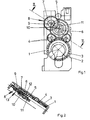
- Figure 1 shows a transmission for a drive rod lock with a base plate 1 and with a receptacle 2 for a lock cylinder, not shown.
- the receptacle 2 has a sprocket 3, which is in communication with two small diameter intermediate gears 4.
- the intermediate gears 4 drive a drive pinion 5 of the transmission.
- the drive pinion 5 is rotatably made with a small diameter gear 6.
- the small diameter gear 6 meshes with a first gear 7 of a gear pair 8.
- a second gear 9 of the gear pair 8 meshes with an output gear 10 of the transmission.
- the output pinion 10 is integrally connected to a steering wheel 11. About the steering wheel 11, a drive rod, not shown, of the espagnolette is driven.
- the base plate 1 has a flange for connection to the espagnolette lock.
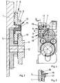
- Figure 2 shows in a sectional view through the transmission of Figure 1 along the line II - II that the drive pinion 5 and the output pinion 10 are arranged sandwiched one above the other. Furthermore, the drive pinion 5 and the output pinion 10 on a common bearing axis 12. The drive pinion 5 is guided into the region of a bearing axis 13 of the gear pair 8.
- Figure 3 shows in a greatly enlarged view of the transmission, the bearing axis 13 of the gear pair 8 outside the range of the drive pinion 5 has a half-axis 14.
- the half-axis 14 allows the assembly of the drive pinion 5 perpendicular to its bearing axis 12.
- a plug-in sleeve 15 is pushed, which has a half-axis 14 corresponding inner cross section and a round outer cross section.
- the gear pair 8 is mounted.
- FIG. 4 shows a further embodiment of the transmission, which differs from that of FIGS. 1 to 3 only in that the gear pair 8 has an outer bearing 16.
- the outer bearing 16 has a plurality of mounted on the base plate 1 shell parts 17, 18.
- Figure 5 shows a sectional view through one of the shell parts 17 and one of Gears 7 of the gear pair 8 that the shell parts 17 which engage over the base plate 1 closest gear 7 of the gear pair 8.
- the gear pair 8 is guided axially and radially on the base plate 1.
Landscapes
- Engineering & Computer Science (AREA)
- Mechanical Engineering (AREA)
- Gear Transmission (AREA)
- Transmission Devices (AREA)
- Lock And Its Accessories (AREA)
- Mechanical Control Devices (AREA)
- Control Of Throttle Valves Provided In The Intake System Or In The Exhaust System (AREA)
- Mechanically-Actuated Valves (AREA)
- Agricultural Chemicals And Associated Chemicals (AREA)
- Nitrogen Condensed Heterocyclic Rings (AREA)
- Control Of Transmission Device (AREA)
- Polysaccharides And Polysaccharide Derivatives (AREA)
- Organic Low-Molecular-Weight Compounds And Preparation Thereof (AREA)
- Materials For Medical Uses (AREA)
Description
- Die Erfindung betrifft ein Getriebe für ein Treibstangenschloss mit einem zur Verbindung mit einem Schließzylinder vorgesehenen Antriebsritzel, mit einem zum Antrieb einer Treibstange vorgesehenen Abtriebsritzel und zwischen dem Antriebsritzel und dem Abtriebsritzel angeordneten, auf einer gemeinsamen Achse gelagerten und drehfest miteinander verbundenen Zahnradpaar, wobei ein erstes Zahnrad des Zahnradpaares mit dem Antriebsritzel verbunden ist und ein zweites Zahnrad des Zahnradpaares mit dem Abtriebsritzel verbunden ist, wobei das Abtriebsritzel, das Antriebsritzel und das Zahnradpaar auf einer Grundplatte gelagert sind.
- Ein solches Getriebe ist beispielsweise aus der EP 0 325 215 B1 bekannt. Hierbei weisen das Getriebe und das Treibstangenschloss eine gemeinsame Grundplatte auf. Die Grundplatte trägt jeweils eine Lagerachse für das Antriebsritzel, das Abtriebsritzel und das Zahnradpaar. Das Antriebsritzel wird über zwei Zwischenzahnräder mit einem von einem Schließzylinder angetriebenen Zahnradkranz verbunden. Das Abtriebsritzel trägt eine Krone zum Antrieb der Treibstange. Eine vorgesehene Übersetzung der Bewegung von dem Schließzylinder auf die Treibstange wird über entsprechende Durchmesser des Zahnradpaares und die Zahnräder des Zahnradpaares kämmende Zahnräder erreicht. Hierfür ist das die Zwischenzahnräder kämmende Antriebsritzel durchmessergroß gestaltet und drehfest mit einem durchmesserkleinen Zahnrad verbunden. Das durchmesserkleine Zahnrad des Antriebsritzels kämmt ein durchmessergroßes Zahnrad des Zahnradpaares und das Abtriebsritzel ist durchmessergroß gestaltet und kämmt ein durchmesserkleines Zahnrad des Zahnradpaares.
- Nachteilig bei dem bekannten Getriebe ist, dass es einen großen Bauraum benötigt, da die auf der Grundplatte angeordneten Lagerachsen die möglichen Durchmesser der Ritzel und der Zahnräder des Zahnradpaares beschränken. Dies führt dazu, dass eine vorgesehene Übersetzung begrenzt ist.
- Der Erfindung liegt das Problem zugrunde, ein Getriebe der eingangs genannten Art so zu gestalten, dass sein Bauraum möglichst gering gehalten wird. Für dieses Problem sollen zwei Lösungen geschaffen werden.
- Die erste Lösung des Problems wird erfindungsgemäß dadurch geschaffen, dass die Lagerachse des Zahnradpaares ein auf der Grundplatte angeordnete Halbachse und eine Steckhülse mit einem der Halbachse angepassten Innenquerschnitt und einen einer Lagerbohrung des Zahnradpaares entsprechenden Außenquerschnitt aufweist.
- Durch diese Gestaltung kann das Antriebsritzel einen besonders großen Durchmesser aufweisen, da die Lagerachse des Zahnradpaares einen geringeren Querschnitt aufweist als bei dem bekannten Getriebe. Wenn beispielsweise die Lagerachse des Zahnradpaares des bekannten Getriebes einen Durchmesser von 6 mm aufweist, kann der Radius des Antriebsritzels durch den Einsatz einer 3 mm breiten Halbachse um 3 mm vergrößert werden. Das Zahnradpaar wird auf der Steckhülse geführt. Die Steckhülse befindet sich außerhalb der Ebene des Antriebsritzels und behindert daher die Bewegung des Antriebsritzels nicht.
- Die Montage des erfindungsgemäßen Getriebes gestaltet sich für unterschiedliche Treibstangenschlösser besonders einfach, wenn die Grundplatte einen Flansch zur Verbindung mit dem Treibstangenschloss aufweist. Durch diese Gestaltung lässt sich das erfindungsgemäße Getriebe einfach vormontieren und in den unterschiedliche Abmessungen aufweisenden Treibstangenschlössern befestigen.
- Die Montage des erfindungsgemäßen Getriebes gestaltet sich besonders einfach, wenn die Halbachse in der Grundplatte vernietet oder einstückig mit dieser ausgebildet ist.
- Zur weiteren Verringerung der Abmessungen des erfindungsgemäßen Getriebes trägt es bei, wenn die Lagerungen des Antriebsritzels und des Abtriebsritzels eine gemeinsame Lagerachse aufweisen. Durch diese Gestaltung sind das Antriebsritzel und das Abtriebsritzel übereinander gelagert. Das Zahnradpaar kann an einer nahezu beliebigen Stelle neben der gemeinsamen Lagerache des Antriebsritzels und des Abtriebsritzels gelagert werden.
- Die zweite Lösung des obengenannten Problems wird erfindungsgemäß dadurch geschaffen, dass das Zahnradpaar eine Außenlagerung aufweist.
- Durch diese Gestaltung wird der Einsatz einer im Zentrum des Zahnradpaares anzuordnenden Lagerachse zur Lagerung vermieden. Das Zahnradpaar lässt sich einfach an dem Zahnkranz einer der Zahnräder führen, so dass das Zentrum des Zahnradpaares von dem Antriebsritzel untergriffen werden kann. Dies führt ebenfalls zu einem besonders geringen Bauraum des erfindungsgemäßen Getriebes.
- Das Zahnradpaar ist gemäß einer vorteilhaften Weiterbildung der Erfindung gleichzeitig radial und axial geführt, wenn eine Lagerschale des Zahnradpaares mehrere, auf der Grundplatte befestigte, eines der Zahnräder übergreifende Schalenteile aufweist.
- Die Erfindung lässt zahlreiche Ausführungsformen zu. Zur weiteren Verdeutlichung ihres Grundprinzips sind zwei davon in der Zeichnung dargestellt und werden nachfolgend beschrieben. Diese zeigt in
- Fig.1
- eine Draufsicht auf ein erfindungsgemäßes Getriebe,
- Fig.2
- eine Schnittdarstellung durch das Getriebe aus Figur 1 entlang der Linie II - II,
- Fig.3
- eine stark vergrößerte Darstellung eines Teilbereichs des Getriebes aus Figur 2,
- Fig.4
- eine Draufsicht auf eine weitere Ausführungsform des erfindungsgemäßen Getriebes,
- Fig.5
- eine Schnittdarstellung durch einen Teilbereich des Getriebes aus Figur 4 entlang der Linie V - V.
- Figur 1 zeigt ein Getriebe für ein Treibstangenschloss mit einer Grundplatte 1 und mit einer Aufnahme 2 für einen nicht dargestellten Schließzylinder. Die Aufnahme 2 weist einen Zahnkranz 3 auf, welcher mit zwei durchmesserkleinen Zwischenzahnrädern 4 in Verbindung steht. Die Zwischenzahnräder 4 treiben ein Antriebsritzel 5 des Getriebes an. Das Antriebsritzel 5 ist drehfest mit einem durchmesserkleinen Zahnrad 6 gefertigt. Das durchmesserkleine Zahnrad 6 kämmt ein erstes Zahnrad 7 eines Zahnradpaares 8. Ein zweites Zahnrad 9 des Zahnradpaares 8 kämmt ein Abtriebsritzel 10 des Getriebes. Das Abtriebsritzel 10 ist einstückig mit einem Steuerrad 11 verbunden. Über das Steuerrad 11 wird eine nicht dargestellte Treibstange des Treibstangenschlosses angetrieben. Die Grundplatte 1 hat einen Flansch zur Verbindung mit dem Treibstangenschloss.
- Figur 2 zeigt in einer Schnittdarstellung durch das Getriebe aus Figur 1 entlang der Linie II - II, dass das Antriebsritzel 5 und das Abtriebsritzel 10 sandwichartig übereinanderliegend angeordnet sind. Weiterhin weisen das Antriebsritzel 5 und das Abtriebsritzel 10 eine gemeinsame Lagerachse 12 auf. Das Antriebsritzel 5 ist bis in den Bereich einer Lagerachse 13 des Zahnradpaares 8 geführt. Wie Figur 3 in einer stark vergrößerten Darstellung des Getriebes zeigt, weist die Lagerachse 13 des Zahnradpaares 8 außerhalb des Bereichs des Antriebsritzels 5 eine Halbachse 14 auf. Die Halbachse 14 ermöglicht die Montage des Antriebsritzels 5 senkrecht zu seiner Lagerachse 12. Auf die Halbachse 14 ist eine Steckhülse 15 geschoben, welche einen der Halbachse 14 entsprechenden Innenquerschnitt und einen runden Außenquerschnitt aufweist. Auf dem Außenquerschnitt ist das Zahnradpaar 8 gelagert.
- Figur 4 zeigt eine weitere Ausführungsform des Getriebes, welche sich von der aus den Figuren 1 bis 3 nur dadurch unterscheidet, dass das Zahnradpaar 8 eine Außenlagerung 16 aufweist. Die Außenlagerung 16 hat mehrere, auf der Grundplatte 1 befestigte Schalenteile 17, 18. Befestigungselemente 19, wie beispielsweise Schrauben oder Nieten, verbinden die Schalenteile 17, 18 mit der Grundplatte 1. Figur 5 zeigt in einer Schnittdarstellung durch eines der Schalenteile 17 und eines der Zahnräder 7 des Zahnradpaares 8, dass die Schalenteile 17 das der Grundplatte 1 am nächsten liegende Zahnrad 7 des Zahnradpaares 8 übergreifen. Damit wird das Zahnradpaar 8 axial und radial auf der Grundplatte 1 geführt.
Claims (6)
- Getriebe für ein Treibstangenschloss mit einem zur Verbindung mit einem Schließzylinder vorgesehenen Antriebsritzel, mit einem zum Antrieb einer Treibstange vorgesehenen Abtriebsritzel und zwischen dem Antriebsritzel und dem Abtriebsritzel angeordneten, auf einer gemeinsamen Achse gelagerten und drehfest miteinander verbundenen Zahnradpaar, wobei ein erstes Zahnrad des Zahnradpaares mit dem Antriebsritzel verbunden ist und ein zweites Zahnrad des Zahnradpaares mit dem Abtriebsritzel verbunden ist, wobei das Abtriebsritzel, das Antriebsritzel und das Zahnradpaar auf einer Grundplatte gelagert sind, dadurch gekennzeichnet, dass die Lagerachse (13) des Zahnradpaares (8) eine auf der Grundplatte (1) angeordnete Halbachse (14) und eine Steckhülse (15) mit einem der Halbachse (14) angepassten Innenquerschnitt und einen einer Lagerbohrung des Zahnradpaares (8) entsprechenden Außenquerschnitt aufweist.
- Getriebe nach Anspruch 1, dadurch gekennzeichnet, dass die Grundplatte (1) einen Flansch zur Verbindung mit dem Treibstangenschloss aufweist.
- Getriebe nach Anspruch 1 oder 2, dadurch gekennzeichnet, dass die Halbachse (14) in der Grundplatte (1) vernietet oder einstückig mit dieser ausgebildet ist.
- Getriebe nach zumindest einem der vorhergehenden Ansprüche, dadurch gekennzeichnet, dass die Lagerungen des Antriebsritzels (5) und des Abtriebsritzels (10) eine gemeinsame Lagerachse (12) aufweisen.
- Getriebe für ein Treibstangenschloss mit einem zur Verbindung mit einem Schließzylinder vorgesehenen Antriebsritzel, mit einem zum Antrieb einer Treibstange vorgesehenen Abtriebsritzel und zwischen dem Antriebsritzel und dem Abtriebsritzel angeordneten, auf einer gemeinsamen Achse gelagerten und drehfest miteinander verbundenen Zahnradpaar, wobei ein erstes Zahnrad des Zahnradpaares mit dem Antriebsritzel verbunden ist und ein zweites Zahnrad des Zahnradpaares mit dem Abtriebsritzel verbunden ist, wobei das Abtriebsritzel, das Antriebsritzel und das Zahnradpaar auf einer Grundplatte gelagert sind, dadurch gekennzeichnet, dass das Zahnradpaar (8) eine Außenlagerung (16) aufweist.
- Getriebe nach Anspruch 5, dadurch gekennzeichnet, dass eine Lagerschale des Zahnradpaares (8) mehrere, auf der Grundplatte (1) befestigte, eines der Zahnräder (7) übergreifende Schalenteile (17, 18) aufweist.
Priority Applications (1)
| Application Number | Priority Date | Filing Date | Title |
|---|---|---|---|
| PL04102787T PL1505232T3 (pl) | 2003-08-06 | 2004-06-17 | Przekładnia zamka baskwilowego rozporowego |
Applications Claiming Priority (2)
| Application Number | Priority Date | Filing Date | Title |
|---|---|---|---|
| DE10335916 | 2003-08-06 | ||
| DE10335916A DE10335916A1 (de) | 2003-08-06 | 2003-08-06 | Getriebe für ein Treibstangenschloss |
Publications (2)
| Publication Number | Publication Date |
|---|---|
| EP1505232A1 EP1505232A1 (de) | 2005-02-09 |
| EP1505232B1 true EP1505232B1 (de) | 2006-07-26 |
Family
ID=33547098
Family Applications (1)
| Application Number | Title | Priority Date | Filing Date |
|---|---|---|---|
| EP04102787A Expired - Lifetime EP1505232B1 (de) | 2003-08-06 | 2004-06-17 | Getriebe für ein Treibstangenschloss |
Country Status (5)
| Country | Link |
|---|---|
| EP (1) | EP1505232B1 (de) |
| AT (1) | ATE334287T1 (de) |
| DE (2) | DE10335916A1 (de) |
| DK (1) | DK1505232T3 (de) |
| PL (1) | PL1505232T3 (de) |
Families Citing this family (4)
| Publication number | Priority date | Publication date | Assignee | Title |
|---|---|---|---|---|
| FR2951764B1 (fr) * | 2009-10-23 | 2011-12-16 | Acs France Sas | Dispositif de fermeture d'une menuiserie de porte, fenetre ou porte-fenetre. |
| FR2951763A1 (fr) * | 2009-10-23 | 2011-04-29 | Acs France Sas | Dispositif de fermeture d'une menuiserie de porte, fenetre ou porte-fenetre, a ouvrant cache et mecanisme de deverrouillage par l'exterieur |
| DE102011055421B4 (de) * | 2011-11-16 | 2014-08-14 | Insys Microelectronics Gmbh | Elektromechanische Verschlussvorrichtung mit einer Schnellverschlusseinrichtung |
| FR3015997B1 (fr) * | 2013-12-31 | 2020-04-17 | Adler S.A.S | Mecanisme d'adaptation pour cylindre a panneton |
Family Cites Families (6)
| Publication number | Priority date | Publication date | Assignee | Title |
|---|---|---|---|---|
| ES2085061T3 (es) * | 1988-01-18 | 1996-05-16 | Winkhaus Fa August | Cerradura con barra motriz. |
| DE29803634U1 (de) * | 1998-03-03 | 1999-07-15 | Karl Fliether Gmbh & Co, 42551 Velbert | Motorangetriebenes Schloß |
| AT406285B (de) * | 1998-07-23 | 2000-03-27 | Roto Frank Eisenwaren | Mehrriegelverschluss |
| DE19901154A1 (de) * | 1999-01-14 | 2000-07-20 | Fliether Karl Gmbh & Co | Treibstangenverschluß mit einem Hauptschloß und einem Nebenschloß, vorzugsweise zwei Nebenschlössern |
| AT4246U1 (de) * | 2000-01-20 | 2001-04-25 | Grundmann Beschlagtechnik Gmbh | Mehrfach-verriegelungssystem |
| DE10204334B4 (de) * | 2002-02-01 | 2005-08-11 | Carl Fuhr Gmbh & Co. Kg | Treibstangenschloss |
-
2003
- 2003-08-06 DE DE10335916A patent/DE10335916A1/de not_active Withdrawn
-
2004
- 2004-06-17 EP EP04102787A patent/EP1505232B1/de not_active Expired - Lifetime
- 2004-06-17 AT AT04102787T patent/ATE334287T1/de active
- 2004-06-17 PL PL04102787T patent/PL1505232T3/pl unknown
- 2004-06-17 DE DE502004001022T patent/DE502004001022D1/de not_active Expired - Lifetime
- 2004-06-17 DK DK04102787T patent/DK1505232T3/da active
Also Published As
| Publication number | Publication date |
|---|---|
| EP1505232A1 (de) | 2005-02-09 |
| DK1505232T3 (da) | 2006-11-20 |
| DE502004001022D1 (de) | 2006-09-07 |
| DE10335916A1 (de) | 2005-03-03 |
| PL1505232T3 (pl) | 2006-11-30 |
| ATE334287T1 (de) | 2006-08-15 |
Similar Documents
| Publication | Publication Date | Title |
|---|---|---|
| DE10217343B4 (de) | Reduktionsgetriebe | |
| EP1266153B1 (de) | Getriebebaukasten | |
| EP0683333B1 (de) | Differential für den Achsantrieb eines Kraftfahrzeuges | |
| EP2642159B1 (de) | Mehrstufiges Planetengetriebe | |
| EP1769174B1 (de) | Differential für eine fahrzeugachse | |
| EP3717724B1 (de) | Spindelantriebsbaugruppe sowie fahrzeugklappe mit einer spindelantriebsbaugruppe | |
| EP2730807B1 (de) | Planetengetriebe mit mehreren Getriebestufen | |
| DE102016201536A1 (de) | Wellgetriebe | |
| EP2572945B1 (de) | Elektrische Lenkverriegelung | |
| DE102012202450A1 (de) | Ausgleichsradlagerung mit Bolzen ohne gehärtete Oberfläche in einer dreiteiligen Lösung | |
| DE102018205473A1 (de) | Lagerung für ein Hybridmodul | |
| DE102011087578A1 (de) | Ausgleichsrad mit Zapfenlagerung | |
| DE102015223914B4 (de) | Umlaufrädergetriebe mit Untersetzungsstufe für eine Kraftfahrzeugantriebseinheit | |
| DE3916945A1 (de) | Pendelgetriebe, insbesondere fuer scheibenwischer an kraftfahrzeugen | |
| DE102018127588A1 (de) | Elektrische Antriebseinheit mit kompakt bauendem Zwischengetriebe | |
| EP1505232B1 (de) | Getriebe für ein Treibstangenschloss | |
| DE102009050121B4 (de) | Untersetzungsgetriebe mit Schnecke und Schneckenrad | |
| EP1334295B1 (de) | Differential für den achsantrieb eines kraftfahrzeuges | |
| EP2733389A1 (de) | Winkelgetriebe | |
| WO2014044277A1 (de) | Getriebeanordnung | |
| EP1526308B1 (de) | Lagervorrichtung, insbesondere für ein Getriebe | |
| WO1998023883A1 (de) | Planetengetriebe, insbesondere zum einsatz in bohrlöchern | |
| EP1373744B1 (de) | Lageranordnung sowie elektroantrieb mit einer solchen lageranordnung | |
| EP1394013A2 (de) | Spielfreies Planetenradgetriebe | |
| DE102020214844A1 (de) | Lenksystem für ein Kraftfahrzeug |
Legal Events
| Date | Code | Title | Description |
|---|---|---|---|
| PUAI | Public reference made under article 153(3) epc to a published international application that has entered the european phase |
Free format text: ORIGINAL CODE: 0009012 |
|
| AK | Designated contracting states |
Kind code of ref document: A1 Designated state(s): AT BE BG CH CY CZ DE DK EE ES FI FR GB GR HU IE IT LI LU MC NL PL PT RO SE SI SK TR |
|
| AX | Request for extension of the european patent |
Extension state: AL HR LT LV MK |
|
| 17P | Request for examination filed |
Effective date: 20050609 |
|
| AKX | Designation fees paid |
Designated state(s): AT BE BG CH CY CZ DE DK EE ES FI FR GB GR HU IE IT LI LU MC NL PL PT RO SE SI SK TR |
|
| GRAP | Despatch of communication of intention to grant a patent |
Free format text: ORIGINAL CODE: EPIDOSNIGR1 |
|
| GRAS | Grant fee paid |
Free format text: ORIGINAL CODE: EPIDOSNIGR3 |
|
| GRAA | (expected) grant |
Free format text: ORIGINAL CODE: 0009210 |
|
| AK | Designated contracting states |
Kind code of ref document: B1 Designated state(s): AT BE BG CH CY CZ DE DK EE ES FI FR GB GR HU IE IT LI LU MC NL PL PT RO SE SI SK TR |
|
| PG25 | Lapsed in a contracting state [announced via postgrant information from national office to epo] |
Ref country code: IT Free format text: LAPSE BECAUSE OF FAILURE TO SUBMIT A TRANSLATION OF THE DESCRIPTION OR TO PAY THE FEE WITHIN THE PRESCRIBED TIME-LIMIT;WARNING: LAPSES OF ITALIAN PATENTS WITH EFFECTIVE DATE BEFORE 2007 MAY HAVE OCCURRED AT ANY TIME BEFORE 2007. THE CORRECT EFFECTIVE DATE MAY BE DIFFERENT FROM THE ONE RECORDED. Effective date: 20060726 Ref country code: RO Free format text: LAPSE BECAUSE OF FAILURE TO SUBMIT A TRANSLATION OF THE DESCRIPTION OR TO PAY THE FEE WITHIN THE PRESCRIBED TIME-LIMIT Effective date: 20060726 Ref country code: SK Free format text: LAPSE BECAUSE OF FAILURE TO SUBMIT A TRANSLATION OF THE DESCRIPTION OR TO PAY THE FEE WITHIN THE PRESCRIBED TIME-LIMIT Effective date: 20060726 Ref country code: SI Free format text: LAPSE BECAUSE OF FAILURE TO SUBMIT A TRANSLATION OF THE DESCRIPTION OR TO PAY THE FEE WITHIN THE PRESCRIBED TIME-LIMIT Effective date: 20060726 Ref country code: IE Free format text: LAPSE BECAUSE OF FAILURE TO SUBMIT A TRANSLATION OF THE DESCRIPTION OR TO PAY THE FEE WITHIN THE PRESCRIBED TIME-LIMIT Effective date: 20060726 Ref country code: FI Free format text: LAPSE BECAUSE OF FAILURE TO SUBMIT A TRANSLATION OF THE DESCRIPTION OR TO PAY THE FEE WITHIN THE PRESCRIBED TIME-LIMIT Effective date: 20060726 Ref country code: CZ Free format text: LAPSE BECAUSE OF FAILURE TO SUBMIT A TRANSLATION OF THE DESCRIPTION OR TO PAY THE FEE WITHIN THE PRESCRIBED TIME-LIMIT Effective date: 20060726 |
|
| REG | Reference to a national code |
Ref country code: GB Ref legal event code: FG4D Free format text: NOT ENGLISH |
|
| REG | Reference to a national code |
Ref country code: CH Ref legal event code: EP |
|
| REG | Reference to a national code |
Ref country code: IE Ref legal event code: FG4D Free format text: LANGUAGE OF EP DOCUMENT: GERMAN |
|
| REF | Corresponds to: |
Ref document number: 502004001022 Country of ref document: DE Date of ref document: 20060907 Kind code of ref document: P |
|
| PG25 | Lapsed in a contracting state [announced via postgrant information from national office to epo] |
Ref country code: BG Free format text: LAPSE BECAUSE OF FAILURE TO SUBMIT A TRANSLATION OF THE DESCRIPTION OR TO PAY THE FEE WITHIN THE PRESCRIBED TIME-LIMIT Effective date: 20061026 Ref country code: SE Free format text: LAPSE BECAUSE OF FAILURE TO SUBMIT A TRANSLATION OF THE DESCRIPTION OR TO PAY THE FEE WITHIN THE PRESCRIBED TIME-LIMIT Effective date: 20061026 |
|
| PG25 | Lapsed in a contracting state [announced via postgrant information from national office to epo] |
Ref country code: ES Free format text: LAPSE BECAUSE OF FAILURE TO SUBMIT A TRANSLATION OF THE DESCRIPTION OR TO PAY THE FEE WITHIN THE PRESCRIBED TIME-LIMIT Effective date: 20061106 |
|
| REG | Reference to a national code |
Ref country code: DK Ref legal event code: T3 |
|
| GBT | Gb: translation of ep patent filed (gb section 77(6)(a)/1977) |
Effective date: 20061101 |
|
| PG25 | Lapsed in a contracting state [announced via postgrant information from national office to epo] |
Ref country code: PT Free format text: LAPSE BECAUSE OF FAILURE TO SUBMIT A TRANSLATION OF THE DESCRIPTION OR TO PAY THE FEE WITHIN THE PRESCRIBED TIME-LIMIT Effective date: 20061226 |
|
| REG | Reference to a national code |
Ref country code: IE Ref legal event code: FD4D |
|
| ET | Fr: translation filed | ||
| PLBE | No opposition filed within time limit |
Free format text: ORIGINAL CODE: 0009261 |
|
| STAA | Information on the status of an ep patent application or granted ep patent |
Free format text: STATUS: NO OPPOSITION FILED WITHIN TIME LIMIT |
|
| 26N | No opposition filed |
Effective date: 20070427 |
|
| BERE | Be: lapsed |
Owner name: AUG. WINKHAUS G.M.B.H. & CO. KG Effective date: 20070630 |
|
| PG25 | Lapsed in a contracting state [announced via postgrant information from national office to epo] |
Ref country code: MC Free format text: LAPSE BECAUSE OF NON-PAYMENT OF DUE FEES Effective date: 20070630 |
|
| PG25 | Lapsed in a contracting state [announced via postgrant information from national office to epo] |
Ref country code: BE Free format text: LAPSE BECAUSE OF NON-PAYMENT OF DUE FEES Effective date: 20070630 |
|
| PG25 | Lapsed in a contracting state [announced via postgrant information from national office to epo] |
Ref country code: GR Free format text: LAPSE BECAUSE OF FAILURE TO SUBMIT A TRANSLATION OF THE DESCRIPTION OR TO PAY THE FEE WITHIN THE PRESCRIBED TIME-LIMIT Effective date: 20061027 |
|
| PG25 | Lapsed in a contracting state [announced via postgrant information from national office to epo] |
Ref country code: EE Free format text: LAPSE BECAUSE OF FAILURE TO SUBMIT A TRANSLATION OF THE DESCRIPTION OR TO PAY THE FEE WITHIN THE PRESCRIBED TIME-LIMIT Effective date: 20060726 |
|
| REG | Reference to a national code |
Ref country code: CH Ref legal event code: PL |
|
| PG25 | Lapsed in a contracting state [announced via postgrant information from national office to epo] |
Ref country code: CH Free format text: LAPSE BECAUSE OF NON-PAYMENT OF DUE FEES Effective date: 20080630 Ref country code: LI Free format text: LAPSE BECAUSE OF NON-PAYMENT OF DUE FEES Effective date: 20080630 |
|
| PGFP | Annual fee paid to national office [announced via postgrant information from national office to epo] |
Ref country code: DK Payment date: 20090611 Year of fee payment: 6 Ref country code: NL Payment date: 20090611 Year of fee payment: 6 |
|
| PG25 | Lapsed in a contracting state [announced via postgrant information from national office to epo] |
Ref country code: LU Free format text: LAPSE BECAUSE OF NON-PAYMENT OF DUE FEES Effective date: 20070617 Ref country code: CY Free format text: LAPSE BECAUSE OF FAILURE TO SUBMIT A TRANSLATION OF THE DESCRIPTION OR TO PAY THE FEE WITHIN THE PRESCRIBED TIME-LIMIT Effective date: 20060726 |
|
| PGFP | Annual fee paid to national office [announced via postgrant information from national office to epo] |
Ref country code: FR Payment date: 20090608 Year of fee payment: 6 |
|
| PG25 | Lapsed in a contracting state [announced via postgrant information from national office to epo] |
Ref country code: TR Free format text: LAPSE BECAUSE OF FAILURE TO SUBMIT A TRANSLATION OF THE DESCRIPTION OR TO PAY THE FEE WITHIN THE PRESCRIBED TIME-LIMIT Effective date: 20060726 Ref country code: HU Free format text: LAPSE BECAUSE OF FAILURE TO SUBMIT A TRANSLATION OF THE DESCRIPTION OR TO PAY THE FEE WITHIN THE PRESCRIBED TIME-LIMIT Effective date: 20070127 |
|
| PGFP | Annual fee paid to national office [announced via postgrant information from national office to epo] |
Ref country code: GB Payment date: 20100401 Year of fee payment: 7 |
|
| REG | Reference to a national code |
Ref country code: NL Ref legal event code: V1 Effective date: 20110101 |
|
| REG | Reference to a national code |
Ref country code: DK Ref legal event code: EBP |
|
| REG | Reference to a national code |
Ref country code: FR Ref legal event code: ST Effective date: 20110228 |
|
| PG25 | Lapsed in a contracting state [announced via postgrant information from national office to epo] |
Ref country code: FR Free format text: LAPSE BECAUSE OF NON-PAYMENT OF DUE FEES Effective date: 20100630 Ref country code: NL Free format text: LAPSE BECAUSE OF NON-PAYMENT OF DUE FEES Effective date: 20110101 |
|
| PG25 | Lapsed in a contracting state [announced via postgrant information from national office to epo] |
Ref country code: DK Free format text: LAPSE BECAUSE OF NON-PAYMENT OF DUE FEES Effective date: 20100630 |
|
| PGFP | Annual fee paid to national office [announced via postgrant information from national office to epo] |
Ref country code: AT Payment date: 20110620 Year of fee payment: 8 Ref country code: PL Payment date: 20110601 Year of fee payment: 8 |
|
| GBPC | Gb: european patent ceased through non-payment of renewal fee |
Effective date: 20110617 |
|
| PG25 | Lapsed in a contracting state [announced via postgrant information from national office to epo] |
Ref country code: GB Free format text: LAPSE BECAUSE OF NON-PAYMENT OF DUE FEES Effective date: 20110617 |
|
| REG | Reference to a national code |
Ref country code: AT Ref legal event code: MM01 Ref document number: 334287 Country of ref document: AT Kind code of ref document: T Effective date: 20120617 |
|
| PG25 | Lapsed in a contracting state [announced via postgrant information from national office to epo] |
Ref country code: AT Free format text: LAPSE BECAUSE OF NON-PAYMENT OF DUE FEES Effective date: 20120617 |
|
| PG25 | Lapsed in a contracting state [announced via postgrant information from national office to epo] |
Ref country code: PL Free format text: LAPSE BECAUSE OF NON-PAYMENT OF DUE FEES Effective date: 20120617 |
|
| REG | Reference to a national code |
Ref country code: PL Ref legal event code: LAPE |
|
| PGFP | Annual fee paid to national office [announced via postgrant information from national office to epo] |
Ref country code: DE Payment date: 20130902 Year of fee payment: 10 |
|
| REG | Reference to a national code |
Ref country code: DE Ref legal event code: R119 Ref document number: 502004001022 Country of ref document: DE |
|
| REG | Reference to a national code |
Ref country code: DE Ref legal event code: R119 Ref document number: 502004001022 Country of ref document: DE Effective date: 20150101 |
|
| PG25 | Lapsed in a contracting state [announced via postgrant information from national office to epo] |
Ref country code: DE Free format text: LAPSE BECAUSE OF NON-PAYMENT OF DUE FEES Effective date: 20150101 |