EP1504964B1 - Dispositif de fixation pour la fixation de module de colonne sur la colonne de direction et module de colonne - Google Patents
Dispositif de fixation pour la fixation de module de colonne sur la colonne de direction et module de colonne Download PDFInfo
- Publication number
- EP1504964B1 EP1504964B1 EP04014208A EP04014208A EP1504964B1 EP 1504964 B1 EP1504964 B1 EP 1504964B1 EP 04014208 A EP04014208 A EP 04014208A EP 04014208 A EP04014208 A EP 04014208A EP 1504964 B1 EP1504964 B1 EP 1504964B1
- Authority
- EP
- European Patent Office
- Prior art keywords
- wedge
- mounting device
- clamping element
- steering column
- foregoing
- Prior art date
- Legal status (The legal status is an assumption and is not a legal conclusion. Google has not performed a legal analysis and makes no representation as to the accuracy of the status listed.)
- Expired - Lifetime
Links
- 239000002184 metal Substances 0.000 claims description 6
- 230000000295 complement effect Effects 0.000 claims description 2
- 239000000463 material Substances 0.000 description 3
- 230000005489 elastic deformation Effects 0.000 description 2
- 238000005452 bending Methods 0.000 description 1
- 230000000694 effects Effects 0.000 description 1
- 238000005516 engineering process Methods 0.000 description 1
- 238000003780 insertion Methods 0.000 description 1
- 230000037431 insertion Effects 0.000 description 1
- 238000004519 manufacturing process Methods 0.000 description 1
- 230000036316 preload Effects 0.000 description 1
- 230000002028 premature Effects 0.000 description 1
- 230000007704 transition Effects 0.000 description 1
- 238000004804 winding Methods 0.000 description 1
Images


Classifications
-
- B—PERFORMING OPERATIONS; TRANSPORTING
- B62—LAND VEHICLES FOR TRAVELLING OTHERWISE THAN ON RAILS
- B62D—MOTOR VEHICLES; TRAILERS
- B62D1/00—Steering controls, i.e. means for initiating a change of direction of the vehicle
- B62D1/02—Steering controls, i.e. means for initiating a change of direction of the vehicle vehicle-mounted
- B62D1/16—Steering columns
-
- B—PERFORMING OPERATIONS; TRANSPORTING
- B60—VEHICLES IN GENERAL
- B60Q—ARRANGEMENT OF SIGNALLING OR LIGHTING DEVICES, THE MOUNTING OR SUPPORTING THEREOF OR CIRCUITS THEREFOR, FOR VEHICLES IN GENERAL
- B60Q1/00—Arrangement of optical signalling or lighting devices, the mounting or supporting thereof or circuits therefor
- B60Q1/02—Arrangement of optical signalling or lighting devices, the mounting or supporting thereof or circuits therefor the devices being primarily intended to illuminate the way ahead or to illuminate other areas of way or environments
- B60Q1/04—Arrangement of optical signalling or lighting devices, the mounting or supporting thereof or circuits therefor the devices being primarily intended to illuminate the way ahead or to illuminate other areas of way or environments the devices being headlights
- B60Q1/14—Arrangement of optical signalling or lighting devices, the mounting or supporting thereof or circuits therefor the devices being primarily intended to illuminate the way ahead or to illuminate other areas of way or environments the devices being headlights having dimming means
- B60Q1/1446—Arrangement of optical signalling or lighting devices, the mounting or supporting thereof or circuits therefor the devices being primarily intended to illuminate the way ahead or to illuminate other areas of way or environments the devices being headlights having dimming means controlled by mechanically actuated switches
- B60Q1/1453—Hand actuated switches
- B60Q1/1461—Multifunction switches for dimming headlights and controlling additional devices, e.g. for controlling direction indicating lights
Definitions
- the present invention is therefore based on the object to propose a fastening device for fastening a longitudinal rod module to the casing tube, which remedies the disadvantages of the prior art.
- a simple, safe and durable attachment of the steering column module to be achieved.
- a fastening device with a sleeve-like clamping element which can be arranged between the jacket tube and a fastening section of the steering column module and which has wedge sections for wedge clamping when rotating about the longitudinal axis with wedge surfaces extending at least substantially parallel to the longitudinal axis.
- the wedge sections viewed in cross-section or in the direction of the longitudinal axis, have a wedge profile.
- the clamping elements can bear indirectly and / or directly on the jacket tube and / or the corresponding attachment portion. In this case, intermediate elements between the clamping element and the jacket tube or the attachment portion may be present.
- the wedge surfaces are formed such that an at least substantially homogeneous surface pressure or line pressure occurs. As a result, the load is evenly distributed over a relatively large area or along a line. Material damaging voltage peaks are avoided.
- a particularly preferred embodiment of the invention results when the wedge surfaces are formed in cross-section as eccentric to the longitudinal axis extending circle segments.
- Circular segments can be realized in a simple manner in terms of manufacturing technology. In addition, they have the advantage that, depending on the choice of the respective radius even with slight twisting of the clamping element, a clamping effect can occur.
- an advantageous, defined line pressure occurs. Depending on the choice of the circle center of the respective circle segment and depending on the radius of the circle segment more or less steep wedge surfaces arise.
- the wedge surfaces in cross section as segments of logarhythmic spirals are formed.
- the wedge sections results in a particularly advantageous, homogeneous surface pressure over a comparatively large wedge surface.
- a further preferred embodiment of the invention is characterized in that the clamping element between the wedge sections has circular segment sections extending centrally to the longitudinal axis.
- the circular segment sections are consequently located on a circular path around the longitudinal axis of the clamping element.
- the provision of circular segment sections has the advantage that the clamping element can be guided during rotation about its longitudinal axis in the region of the circular segment sections.
- a wedge clamping consequently does not occur in the region of the circular segment section, but only on the wedge sections.
- the angle which a circle segment section encloses is approximately 80 ° to 110 °.
- the angle, which includes a wedge portion, is advantageously about 40 ° to 20 °. Particularly advantageous values result when the angle of the circle segment section is 90 ° and the angle of the wedge section is 30 °.
- the clamping element has a groove-like recess which extends in the longitudinal direction and adjacent to a wedge portion.
- a recess adjoins each wedge section, specifically to the steeper flank of the wedge section. This ensures a similar flexibility of the wedge sections, whereby a good self-centering is achieved.
- the torsion means comprise a helical toothing, which is suitable for engagement of a counter-toothing of an adjusting bolt.
- a corresponding adjusting bolt which may for example be arranged transversely to the longitudinal axis of the clamping element, a rotation of the clamping element can be realized in a simple manner.
- the adjusting bolt which may be arranged for example mounted in the steering column module, preferably has an engagement portion, can engage in the known bolt driver.
- the torsion means comprise a receptacle for an adjusting screw such that the adjusting screw is received perpendicular to the longitudinal axis and, when the adjusting screw is rotated, the clamping element is rotated relative to the steering column module and the jacket tube.
- the receptacle advantageously has a thread into which the adjusting screw can be screwed.
- the adjusting screw is supported at the same time with its free end on the steering column module. By turning the adjusting screw, therefore, the clamping element rotates about the longitudinal axis, while the adjusting screw is supported on the steering column module.
- the force receiving means may then be formed as a metal ring surrounding the outside.
- a steering column module comprising a fastening device according to the invention.
- the steering column module in addition to the clamping element also include the adjusting bolt and the metal ring.
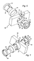
- FIG. 1 shows an inventive steering column module 10 with a fastening device 12 according to the invention.
- the steering column module 10 receives switches, not shown, which are actuated by means of switching levers 14 shown.
- the steering column switch module 10 comprises a central opening 16 into which the one end of a steering column 18 protrudes. This end of the steering column is rotatably connected in the assembled state with a steering wheel, not shown.
- the steering column 18 is surrounded by a jacket tube 20 in the region of the steering column module 10.
- a rotor of a coil spring and / or a steering angle sensor can be arranged rotatably mounted.
- the steering column module 10 has a Attachment section 22 for fixing the casing tube 20.
- the attachment portion 22 is surrounded on the outer side by a metal ring 24.
- a clamping element 28 is pushed between the jacket tube 20 and the attachment section 22 from the side facing away from the jacket tube 26.
- the clamping element has on the mounting portion 22 facing radial outside three identically formed, evenly over the circumference of the clamping element 28 arranged wedge portions 30.
- the three wedge sections 30 correspond to counterwedge sections 32 provided on the attachment section 22.
- the wedge sections 30 and the counterwedge sections 32 are formed complementary to one another.
- the wedge sections 30 can be introduced into the counter wedge sections 32 in the axial direction.
- the wedge portions 30 and the counter wedge portions 32 have wedge surfaces 31, which consist of segments of logarithmic spirals. Such wedge surfaces are shown in FIG. 5 by way of example on circular wedge profiles.
- the radially inner inner surface 34 of the clamping element 28 has a circular, the jacket tube 26 surrounding cross-section.
- the sleeve-like fastening portion 22 has on the radially outer, the clamping member 28 remote from the outside 36 has a circular cross section, of the Metal ring 24 is surrounded.
- the metal ring 24 absorbs the forces acting radially and prevents unwanted deformation of the fastening portion 22.
- the clamping element 54 facing side of the mounting portion 22 has counter-wedge portions 60, which also have a circular-segment-shaped surface.
- the radius of these surfaces may correspond to the radius of the wedge sections 56.
- an advantageous embodiment results when the radius of the surfaces of the counter-wedge sections 60 is different from the radius of the wedge sections 56.
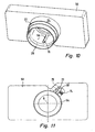
- a circumferential collar 66 with a screw receptacle 68 is provided on the clamping element 54.
- the screw receptacle 68 comprises a threaded bore 70 running perpendicular to the longitudinal axis into which a set screw 72 shown in FIG. 11 can be screwed.
- the free end of the adjusting screw 72 is supported on a support 74 of the steering column module 50.
- the screw receptacle 68 moves such that the clamping element 54 is rotated against the steering column module 50 about its longitudinal axis.
- a Recess 76 provided by the adjusting screw 72 is accessible and can be rotated.
Landscapes
- Engineering & Computer Science (AREA)
- Mechanical Engineering (AREA)
- Chemical & Material Sciences (AREA)
- Combustion & Propulsion (AREA)
- Transportation (AREA)
- Clamps And Clips (AREA)
- Steering Controls (AREA)
- Mutual Connection Of Rods And Tubes (AREA)
Claims (24)
- Dispositif de fixation (12, 52) pour la fixation d'un module de commande (10) sur le tube extérieur (20) d'une colonne de direction, comportant un élément de serrage (28, 54) en forme de manchon, qui est destiné à être agencé entre le tube extérieur (20) et une partie de fixation (22) du module de commande (10) et qui comporte des parties en clavette (30, 56) avec des surfaces de calage (31) au moins en grande partie parallèles à l'axe longitudinal pour un serrage par calage lors d'une rotation autour de l'axe longitudinal.
- Dispositif de fixation (12, 52) selon la revendication 1, caractérisé en ce que les parties en clavette (30, 56) sont agencées en étant réparties au moins en grande partie identiquement et uniformément sur le pourtour de l'élément de serrage (28, 54).
- Dispositif de fixation (12, 52) selon la revendication 1 ou 2, caractérisé en ce que l'élément de serrage (28, 54) et/ou le tube extérieur (20) ont une section au moins partiellement ouverte ou fermée.
- Dispositif de fixation (12, 52) selon la revendication 1, 2 ou 3, caractérisé en ce que les parties en clavette (30) s'étendent au moins en grande partie sur toute la longueur de l'élément de serrage (28, 54).
- Dispositif de fixation (12, 52) selon l'une quelconque des revendications précédentes, caractérisé en ce que la face intérieure (34) de l'élément de serrage (28, 54), située radialement à l'intérieur, a une section ronde.
- Dispositif de fixation (12, 52) selon l'une quelconque des revendications précédentes, caractérisé en ce que les parties en clavette (30) sont agencées sur la face extérieure de l'élément de serrage (28), située radialement à l'extérieur.
- Dispositif de fixation (12, 52) selon l'une quelconque des revendications précédentes, caractérisé en ce que les parties en clavette (30, 56) coopèrent avec des parties en contre-clavette (32, 60) au moins en grande partie complémentaires, agencées sur le tube extérieur (20), plus précisément la partie de fixation (22).
- Dispositif de fixation (12, 52) selon l'une quelconque des revendications précédentes, caractérisé en ce que les surfaces de calage (31) sont conçues de telle sorte qu'il se produit un pressage par surface au moins en grande partie homogène ou un pressage par ligne.
- Dispositif de fixation (12, 52) selon l'une quelconque des revendications précédentes, caractérisé en ce que les surfaces de calage (31) ont une petite pente de calage, de telle sorte qu'il peut se produire un autoblocage.
- Dispositif de fixation (12, 52) selon l'une quelconque des revendications précédentes, caractérisé en ce que les surfaces de calage (31) sont réalisées sous forme de segments de cercle qui, par référence à une coupe transversale, sont excentrés par rapport à l'axe longitudinal (A).
- Dispositif de fixation (12) selon l'une quelconque des revendications 1 à 9, caractérisé en ce que les surfaces de calage (31) sont réalisées, par référence à une coupe transversale, sous forme de segments de spirales logarithmiques.
- Dispositif de fixation (52) selon l'une quelconque des revendications précédentes, caractérisé en ce que l'élément de serrage (54) comporte des parties en segments de cercle (58) qui s'étendent entre les parties en clavette en étant centrées par rapport à l'axe longitudinal.
- Dispositif de fixation (52) selon la revendication 12, caractérisé en ce que, par référence à une coupe transversale, les parties en segments de cercle (58) forment chacune un angle (α), qui est 2,5 à 3,5 fois supérieur à l'angle (β) qui est formé par les différentes parties en clavette (56).
- Dispositif de fixation (52) selon la revendication 12 ou 13, caractérisé en ce qu'une partie en segment de cercle (58) forme un angle (α) de 80° à 110° et en ce qu'une partie en clavette (56) forme un angle (β) de 40° à 20°.
- Dispositif de fixation (52) selon l'une quelconque des revendications précédentes, caractérisé en ce qu'il est prévu un évidement (62) en forme de rainure, orienté dans le sens longitudinal et adjacent à une partie en clavette (56).
- Dispositif de fixation (52) selon la revendication 12 ou 15, caractérisé en ce que l'évidement (62) en forme de rainure s'étend dans le sens périphérique (64) également sur le côté opposé au tube extérieur.
- Dispositif de fixation (52) selon la revendication 16, caractérisé en ce que l'évidement (64) s'étend dans le sens périphérique au moins sur la longueur de la partie en clavette (56).
- Dispositif de fixation (12, 52) selon l'une quelconque des revendications précédentes, caractérisé en ce que l'élément de serrage (28, 54) comporte, sur la face extérieure radiale, des moyens de rotation (40, 68) qui permettent de faire tourner l'élément de serrage (28, 54).
- Dispositif de fixation (12) selon la revendication 18, caractérisé en ce que les moyens de rotation sont formés par une denture hélicoïdale (40), qui est destinée à engrener avec une denture complémentaire (46) d'un boulon de réglage (42).
- Dispositif de fixation (52) selon la revendication 18, caractérisé en ce que les moyens de rotation sont formés par un logement (68) pour une vis de réglage (72), de telle sorte que la vis de réglage est reçue perpendiculairement à l'axe longitudinal (A) et que, au moment de la rotation de la vis de réglage (72), l'élément de serrage (54) est entraîné en rotation par rapport au module de commande (50) et au tube extérieur (20).
- Dispositif de fixation (12, 52) selon l'une quelconque des revendications précédentes, caractérisé en ce que la partie de fixation (22), sur la face extérieure (36) opposée à l'élément de serrage et située radialement à l'extérieur, comporte un moyen d'absorption de force (24) destiné à absorber les forces radiales générées pendant la rotation de l'élément de serrage (28).
- Dispositif de fixation (12) selon la revendication 21, caractérisé en ce que la face extérieure (36) de la partie de fixation est circulaire par référence à une coupe transversale.
- Dispositif de fixation (12) selon la revendication 21 ou 22, caractérisé en ce que le moyen d'absorption de force est réalisé sous forme de bague métallique (24) entourant la face extérieure (36).
- Module de commande (10) comportant un dispositif de fixation (12) selon l'une quelconque des revendications précédentes.
Applications Claiming Priority (4)
| Application Number | Priority Date | Filing Date | Title |
|---|---|---|---|
| DE2003130481 DE10330481A1 (de) | 2003-07-01 | 2003-07-01 | Befestigungseinrichtung zur Befestigung eines Lenkstockmoduls an einem Lenkstock und Lenkstockmodul |
| DE10330481 | 2003-07-01 | ||
| DE10336302 | 2003-07-31 | ||
| DE10336302A DE10336302A1 (de) | 2003-07-01 | 2003-07-31 | Befestigungseinrichtung zur Befestigung eines Lenkstockmoduls an einem Lenkstock und Lenkstockmodul |
Publications (2)
| Publication Number | Publication Date |
|---|---|
| EP1504964A1 EP1504964A1 (fr) | 2005-02-09 |
| EP1504964B1 true EP1504964B1 (fr) | 2006-07-05 |
Family
ID=33553482
Family Applications (1)
| Application Number | Title | Priority Date | Filing Date |
|---|---|---|---|
| EP04014208A Expired - Lifetime EP1504964B1 (fr) | 2003-07-01 | 2004-06-17 | Dispositif de fixation pour la fixation de module de colonne sur la colonne de direction et module de colonne |
Country Status (3)
| Country | Link |
|---|---|
| EP (1) | EP1504964B1 (fr) |
| AT (1) | ATE332252T1 (fr) |
| DE (2) | DE10336302A1 (fr) |
Families Citing this family (2)
| Publication number | Priority date | Publication date | Assignee | Title |
|---|---|---|---|---|
| FR2950850B1 (fr) * | 2009-10-02 | 2012-01-13 | Renault Sa | Systeme de fixation d'un module pour haut de colonne de direction. |
| FR2977206A1 (fr) * | 2011-06-29 | 2013-01-04 | Peugeot Citroen Automobiles Sa | Systeme de fixation des commandes secondaires situees sous le volant d'un vehicule automobile |
Family Cites Families (4)
| Publication number | Priority date | Publication date | Assignee | Title |
|---|---|---|---|---|
| FR2724696B1 (fr) * | 1994-09-20 | 1997-01-24 | Magneti Marelli France | Systeme de fixation d'un ensemble sur une colonne, notamment pour la fixation d'un ensemble de commutation electrique sur une colonne de direction de vehicule automobile |
| FR2749354B1 (fr) * | 1996-05-30 | 1998-08-07 | Valeo Electronique | Support de commutateurs a collier de fixation pour vehicule automobile |
| DE10051226A1 (de) * | 2000-10-16 | 2002-04-25 | Eaton Corp | Lenkstockschalter für ein Kraftfahrzeug |
| JP2002131047A (ja) * | 2000-10-20 | 2002-05-09 | Niles Parts Co Ltd | コンビネーションスイッチ |
-
2003
- 2003-07-31 DE DE10336302A patent/DE10336302A1/de not_active Ceased
-
2004
- 2004-06-17 AT AT04014208T patent/ATE332252T1/de not_active IP Right Cessation
- 2004-06-17 DE DE502004000907T patent/DE502004000907D1/de not_active Expired - Lifetime
- 2004-06-17 EP EP04014208A patent/EP1504964B1/fr not_active Expired - Lifetime
Also Published As
| Publication number | Publication date |
|---|---|
| DE10336302A1 (de) | 2005-04-21 |
| DE502004000907D1 (de) | 2006-08-17 |
| ATE332252T1 (de) | 2006-07-15 |
| EP1504964A1 (fr) | 2005-02-09 |
Similar Documents
| Publication | Publication Date | Title |
|---|---|---|
| DE60017982T2 (de) | Elektrische Servolenkung | |
| EP3717786B1 (fr) | Dispositif de compensation de tolérance avec sécurité par serrage | |
| DE102016200102B4 (de) | Aktuator, insbesondere für eine Hinterachslenkung eines Kraftfahrzeuges | |
| WO2012022310A2 (fr) | Dispositif destiné à appliquer une crémaillère | |
| DE102010050175B4 (de) | Kugelgewindemutter | |
| WO2004033834A1 (fr) | Dispositif d'engrenage conçu en particulier pour des mecanismes de reglage de vehicules automobiles | |
| DE102017209563A1 (de) | Loslager, Lenkgetriebe und Lenksystem | |
| DE102018204263A1 (de) | Spindelantrieb, Verfahren zum Herstellen eines Spindelantriebs sowie Komfortantrieb | |
| EP2264327A1 (fr) | Système pour relier un arbre à une articulation | |
| EP3700802A1 (fr) | Dispositif de précontrainte | |
| EP1504964B1 (fr) | Dispositif de fixation pour la fixation de module de colonne sur la colonne de direction et module de colonne | |
| WO2010081733A1 (fr) | Entraînement pour un composant réglable | |
| DE102012021102A1 (de) | Strebe mit einer durchgehenden Öffnung, insbesondere zur Versteifung eines Kraftfahrzeuges | |
| DE19603893C1 (de) | Vorrichtung zum automatischen Seillängenausgleich eines Bowdenrohr-Fensterhebers | |
| EP2659152B1 (fr) | Unité d'entraînement avec dispositif de palier et entraînement de réglage | |
| DE102010039202A1 (de) | Zahnstangenlenkung | |
| WO2019134814A1 (fr) | Mécanisme de direction pour véhicule automobile | |
| DE102005005400A1 (de) | Vorrichtung zum Andrücken einer Zahnstange an ein mit der Zahnstange in Eingriff stehendes Ritzel | |
| WO2017211513A1 (fr) | Actionneur pour essieu arrière directeur | |
| DE102021209478A1 (de) | Gurtaufroller für einen Sicherheitsgurt | |
| DE10330481A1 (de) | Befestigungseinrichtung zur Befestigung eines Lenkstockmoduls an einem Lenkstock und Lenkstockmodul | |
| EP1439978B1 (fr) | Unite d'entrainement a engrenage munie d'un adaptateur | |
| DE102015111258A1 (de) | Lenkgetriebe und verfahren zur montage eines solchen lenkgetriebes | |
| EP2067652A2 (fr) | Elément d'adaptateur et mécanisme de réglage doté d'un élément d'adaptateur | |
| DE19906693C1 (de) | Stellantrieb, insbesondere für Heizungs-, Lüftungs-, oder Klimaklappen im Kfz |
Legal Events
| Date | Code | Title | Description |
|---|---|---|---|
| PUAI | Public reference made under article 153(3) epc to a published international application that has entered the european phase |
Free format text: ORIGINAL CODE: 0009012 |
|
| AK | Designated contracting states |
Kind code of ref document: A1 Designated state(s): AT BE BG CH CY CZ DE DK EE ES FI FR GB GR HU IE IT LI LU MC NL PL PT RO SE SI SK TR |
|
| AX | Request for extension of the european patent |
Extension state: AL HR LT LV MK |
|
| 17P | Request for examination filed |
Effective date: 20050406 |
|
| AKX | Designation fees paid |
Designated state(s): AT BE BG CH CY CZ DE DK EE ES FI FR GB GR HU IE IT LI LU MC NL PL PT RO SE SI SK TR |
|
| GRAP | Despatch of communication of intention to grant a patent |
Free format text: ORIGINAL CODE: EPIDOSNIGR1 |
|
| GRAS | Grant fee paid |
Free format text: ORIGINAL CODE: EPIDOSNIGR3 |
|
| GRAA | (expected) grant |
Free format text: ORIGINAL CODE: 0009210 |
|
| RIN1 | Information on inventor provided before grant (corrected) |
Inventor name: HASCH, MARTIN Inventor name: GRUENER, ROLAND Inventor name: BINDER, BERND Inventor name: SIMONIS, KARL Inventor name: SUCHANEK, JUERGEN Inventor name: LIPFERT, RAINER |
|
| AK | Designated contracting states |
Kind code of ref document: B1 Designated state(s): AT BE BG CH CY CZ DE DK EE ES FI FR GB GR HU IE IT LI LU MC NL PL PT RO SE SI SK TR |
|
| PG25 | Lapsed in a contracting state [announced via postgrant information from national office to epo] |
Ref country code: PL Free format text: LAPSE BECAUSE OF FAILURE TO SUBMIT A TRANSLATION OF THE DESCRIPTION OR TO PAY THE FEE WITHIN THE PRESCRIBED TIME-LIMIT Effective date: 20060705 Ref country code: FI Free format text: LAPSE BECAUSE OF FAILURE TO SUBMIT A TRANSLATION OF THE DESCRIPTION OR TO PAY THE FEE WITHIN THE PRESCRIBED TIME-LIMIT Effective date: 20060705 Ref country code: CZ Free format text: LAPSE BECAUSE OF FAILURE TO SUBMIT A TRANSLATION OF THE DESCRIPTION OR TO PAY THE FEE WITHIN THE PRESCRIBED TIME-LIMIT Effective date: 20060705 Ref country code: IT Free format text: LAPSE BECAUSE OF FAILURE TO SUBMIT A TRANSLATION OF THE DESCRIPTION OR TO PAY THE FEE WITHIN THE PRESCRIBED TIME-LIMIT;WARNING: LAPSES OF ITALIAN PATENTS WITH EFFECTIVE DATE BEFORE 2007 MAY HAVE OCCURRED AT ANY TIME BEFORE 2007. THE CORRECT EFFECTIVE DATE MAY BE DIFFERENT FROM THE ONE RECORDED. Effective date: 20060705 Ref country code: NL Free format text: LAPSE BECAUSE OF FAILURE TO SUBMIT A TRANSLATION OF THE DESCRIPTION OR TO PAY THE FEE WITHIN THE PRESCRIBED TIME-LIMIT Effective date: 20060705 Ref country code: GB Free format text: LAPSE BECAUSE OF FAILURE TO SUBMIT A TRANSLATION OF THE DESCRIPTION OR TO PAY THE FEE WITHIN THE PRESCRIBED TIME-LIMIT Effective date: 20060705 Ref country code: IE Free format text: LAPSE BECAUSE OF FAILURE TO SUBMIT A TRANSLATION OF THE DESCRIPTION OR TO PAY THE FEE WITHIN THE PRESCRIBED TIME-LIMIT Effective date: 20060705 Ref country code: RO Free format text: LAPSE BECAUSE OF FAILURE TO SUBMIT A TRANSLATION OF THE DESCRIPTION OR TO PAY THE FEE WITHIN THE PRESCRIBED TIME-LIMIT Effective date: 20060705 Ref country code: SK Free format text: LAPSE BECAUSE OF FAILURE TO SUBMIT A TRANSLATION OF THE DESCRIPTION OR TO PAY THE FEE WITHIN THE PRESCRIBED TIME-LIMIT Effective date: 20060705 Ref country code: SI Free format text: LAPSE BECAUSE OF FAILURE TO SUBMIT A TRANSLATION OF THE DESCRIPTION OR TO PAY THE FEE WITHIN THE PRESCRIBED TIME-LIMIT Effective date: 20060705 |
|
| REG | Reference to a national code |
Ref country code: GB Ref legal event code: FG4D Free format text: NOT ENGLISH |
|
| REG | Reference to a national code |
Ref country code: CH Ref legal event code: EP |
|
| REG | Reference to a national code |
Ref country code: IE Ref legal event code: FG4D Free format text: LANGUAGE OF EP DOCUMENT: GERMAN |
|
| REF | Corresponds to: |
Ref document number: 502004000907 Country of ref document: DE Date of ref document: 20060817 Kind code of ref document: P |
|
| PG25 | Lapsed in a contracting state [announced via postgrant information from national office to epo] |
Ref country code: DK Free format text: LAPSE BECAUSE OF FAILURE TO SUBMIT A TRANSLATION OF THE DESCRIPTION OR TO PAY THE FEE WITHIN THE PRESCRIBED TIME-LIMIT Effective date: 20061005 Ref country code: BG Free format text: LAPSE BECAUSE OF FAILURE TO SUBMIT A TRANSLATION OF THE DESCRIPTION OR TO PAY THE FEE WITHIN THE PRESCRIBED TIME-LIMIT Effective date: 20061005 Ref country code: SE Free format text: LAPSE BECAUSE OF FAILURE TO SUBMIT A TRANSLATION OF THE DESCRIPTION OR TO PAY THE FEE WITHIN THE PRESCRIBED TIME-LIMIT Effective date: 20061005 |
|
| PG25 | Lapsed in a contracting state [announced via postgrant information from national office to epo] |
Ref country code: ES Free format text: LAPSE BECAUSE OF FAILURE TO SUBMIT A TRANSLATION OF THE DESCRIPTION OR TO PAY THE FEE WITHIN THE PRESCRIBED TIME-LIMIT Effective date: 20061016 |
|
| NLV1 | Nl: lapsed or annulled due to failure to fulfill the requirements of art. 29p and 29m of the patents act | ||
| PG25 | Lapsed in a contracting state [announced via postgrant information from national office to epo] |
Ref country code: PT Free format text: LAPSE BECAUSE OF FAILURE TO SUBMIT A TRANSLATION OF THE DESCRIPTION OR TO PAY THE FEE WITHIN THE PRESCRIBED TIME-LIMIT Effective date: 20061205 |
|
| GBV | Gb: ep patent (uk) treated as always having been void in accordance with gb section 77(7)/1977 [no translation filed] |
Effective date: 20060705 |
|
| ET | Fr: translation filed | ||
| REG | Reference to a national code |
Ref country code: IE Ref legal event code: FD4D |
|
| PLBE | No opposition filed within time limit |
Free format text: ORIGINAL CODE: 0009261 |
|
| STAA | Information on the status of an ep patent application or granted ep patent |
Free format text: STATUS: NO OPPOSITION FILED WITHIN TIME LIMIT |
|
| 26N | No opposition filed |
Effective date: 20070410 |
|
| BERE | Be: lapsed |
Owner name: VALEO SCHALTER UND SENSOREN G.M.B.H. Effective date: 20070630 |
|
| PG25 | Lapsed in a contracting state [announced via postgrant information from national office to epo] |
Ref country code: MC Free format text: LAPSE BECAUSE OF NON-PAYMENT OF DUE FEES Effective date: 20070630 |
|
| PG25 | Lapsed in a contracting state [announced via postgrant information from national office to epo] |
Ref country code: BE Free format text: LAPSE BECAUSE OF NON-PAYMENT OF DUE FEES Effective date: 20070630 |
|
| PG25 | Lapsed in a contracting state [announced via postgrant information from national office to epo] |
Ref country code: GR Free format text: LAPSE BECAUSE OF FAILURE TO SUBMIT A TRANSLATION OF THE DESCRIPTION OR TO PAY THE FEE WITHIN THE PRESCRIBED TIME-LIMIT Effective date: 20061006 |
|
| PG25 | Lapsed in a contracting state [announced via postgrant information from national office to epo] |
Ref country code: EE Free format text: LAPSE BECAUSE OF FAILURE TO SUBMIT A TRANSLATION OF THE DESCRIPTION OR TO PAY THE FEE WITHIN THE PRESCRIBED TIME-LIMIT Effective date: 20060705 |
|
| PG25 | Lapsed in a contracting state [announced via postgrant information from national office to epo] |
Ref country code: AT Free format text: LAPSE BECAUSE OF NON-PAYMENT OF DUE FEES Effective date: 20070617 |
|
| REG | Reference to a national code |
Ref country code: CH Ref legal event code: PL |
|
| PG25 | Lapsed in a contracting state [announced via postgrant information from national office to epo] |
Ref country code: CH Free format text: LAPSE BECAUSE OF NON-PAYMENT OF DUE FEES Effective date: 20080630 Ref country code: LI Free format text: LAPSE BECAUSE OF NON-PAYMENT OF DUE FEES Effective date: 20080630 |
|
| PG25 | Lapsed in a contracting state [announced via postgrant information from national office to epo] |
Ref country code: CY Free format text: LAPSE BECAUSE OF FAILURE TO SUBMIT A TRANSLATION OF THE DESCRIPTION OR TO PAY THE FEE WITHIN THE PRESCRIBED TIME-LIMIT Effective date: 20060705 Ref country code: LU Free format text: LAPSE BECAUSE OF NON-PAYMENT OF DUE FEES Effective date: 20070617 |
|
| PG25 | Lapsed in a contracting state [announced via postgrant information from national office to epo] |
Ref country code: TR Free format text: LAPSE BECAUSE OF FAILURE TO SUBMIT A TRANSLATION OF THE DESCRIPTION OR TO PAY THE FEE WITHIN THE PRESCRIBED TIME-LIMIT Effective date: 20060705 Ref country code: HU Free format text: LAPSE BECAUSE OF FAILURE TO SUBMIT A TRANSLATION OF THE DESCRIPTION OR TO PAY THE FEE WITHIN THE PRESCRIBED TIME-LIMIT Effective date: 20070106 |
|
| REG | Reference to a national code |
Ref country code: FR Ref legal event code: PLFP Year of fee payment: 13 |
|
| REG | Reference to a national code |
Ref country code: FR Ref legal event code: PLFP Year of fee payment: 14 |
|
| REG | Reference to a national code |
Ref country code: FR Ref legal event code: PLFP Year of fee payment: 15 |
|
| PGFP | Annual fee paid to national office [announced via postgrant information from national office to epo] |
Ref country code: FR Payment date: 20180627 Year of fee payment: 15 |
|
| PG25 | Lapsed in a contracting state [announced via postgrant information from national office to epo] |
Ref country code: FR Free format text: LAPSE BECAUSE OF NON-PAYMENT OF DUE FEES Effective date: 20190630 |
|
| P01 | Opt-out of the competence of the unified patent court (upc) registered |
Effective date: 20230528 |
|
| PGFP | Annual fee paid to national office [announced via postgrant information from national office to epo] |
Ref country code: DE Payment date: 20230613 Year of fee payment: 20 |
|
| REG | Reference to a national code |
Ref country code: DE Ref legal event code: R071 Ref document number: 502004000907 Country of ref document: DE |