EP1504964B1 - Mounting device for fastening a steering column module on the steering column and a steering column module - Google Patents
Mounting device for fastening a steering column module on the steering column and a steering column module Download PDFInfo
- Publication number
- EP1504964B1 EP1504964B1 EP04014208A EP04014208A EP1504964B1 EP 1504964 B1 EP1504964 B1 EP 1504964B1 EP 04014208 A EP04014208 A EP 04014208A EP 04014208 A EP04014208 A EP 04014208A EP 1504964 B1 EP1504964 B1 EP 1504964B1
- Authority
- EP
- European Patent Office
- Prior art keywords
- wedge
- mounting device
- clamping element
- steering column
- foregoing
- Prior art date
- Legal status (The legal status is an assumption and is not a legal conclusion. Google has not performed a legal analysis and makes no representation as to the accuracy of the status listed.)
- Active
Links
Images


Classifications
-
- B—PERFORMING OPERATIONS; TRANSPORTING
- B62—LAND VEHICLES FOR TRAVELLING OTHERWISE THAN ON RAILS
- B62D—MOTOR VEHICLES; TRAILERS
- B62D1/00—Steering controls, i.e. means for initiating a change of direction of the vehicle
- B62D1/02—Steering controls, i.e. means for initiating a change of direction of the vehicle vehicle-mounted
- B62D1/16—Steering columns
-
- B—PERFORMING OPERATIONS; TRANSPORTING
- B60—VEHICLES IN GENERAL
- B60Q—ARRANGEMENT OF SIGNALLING OR LIGHTING DEVICES, THE MOUNTING OR SUPPORTING THEREOF OR CIRCUITS THEREFOR, FOR VEHICLES IN GENERAL
- B60Q1/00—Arrangement of optical signalling or lighting devices, the mounting or supporting thereof or circuits therefor
- B60Q1/02—Arrangement of optical signalling or lighting devices, the mounting or supporting thereof or circuits therefor the devices being primarily intended to illuminate the way ahead or to illuminate other areas of way or environments
- B60Q1/04—Arrangement of optical signalling or lighting devices, the mounting or supporting thereof or circuits therefor the devices being primarily intended to illuminate the way ahead or to illuminate other areas of way or environments the devices being headlights
- B60Q1/14—Arrangement of optical signalling or lighting devices, the mounting or supporting thereof or circuits therefor the devices being primarily intended to illuminate the way ahead or to illuminate other areas of way or environments the devices being headlights having dimming means
- B60Q1/1446—Arrangement of optical signalling or lighting devices, the mounting or supporting thereof or circuits therefor the devices being primarily intended to illuminate the way ahead or to illuminate other areas of way or environments the devices being headlights having dimming means controlled by mechanically actuated switches
- B60Q1/1453—Hand actuated switches
- B60Q1/1461—Multifunction switches for dimming headlights and controlling additional devices, e.g. for controlling direction indicating lights
Landscapes
- Engineering & Computer Science (AREA)
- Mechanical Engineering (AREA)
- Chemical & Material Sciences (AREA)
- Combustion & Propulsion (AREA)
- Transportation (AREA)
- Clamps And Clips (AREA)
- Steering Controls (AREA)
- Mutual Connection Of Rods And Tubes (AREA)
Abstract
Description
Die Erfindung betrifft eine Befestigungseinrichtung zur Befestigung eines Lenkstockmoduls an einem Mantelrohr eines Lenkstocks und ein Lenkstockmodul.The invention relates to a fastening device for fastening a steering column module to a jacket tube of a steering column and a steering column module.
Lenkstockmodule, die in der Regel im Bereich des Lenkrads eines Fahrzeuges angeordnet sind, weisen eine Reihe von Schaltern, wie beispielsweise Fahrtrichtungsschalter, Abblendlichtschalter, Aufblendlichtschalter, Scheibenwischerschalter oder dergleichen auf. Ferner können die Lenkstockmodule Lenkwinkelsensoren beherbergen, mit denen der Verdrehwinkel der Lenksäule erfasst werden kann. Außerdem dienen die Lenkstockmodule zur Aufnahme einer sogenannten Wickelfeder, mit der Signale, die lenkradseitig erzeugt werden, zu mit dem Lenkrad nicht mitdrehende Komponenten übertragen werden. Wickelfedern sind in der Regel als Flachbandkabel ausgebildet, die schneckenförmig um die Drehachse der Lenksäule bzw. des Lenkrades aufgewickelt sind. Bekannte Lenkstockmodule umfassen außerdem Achsversatzausgleichsmittel, die einen Achsersatz der Längsachse der Lenksäule zu der Drehachse eines Rotors einer Wickelfeder oder eines Lenkwinkelsensors ausgleichen.Steering stick modules, which are usually arranged in the region of the steering wheel of a vehicle, have a number of switches, such as direction switch, low beam switch, headlight switch, windscreen wiper switch or the like. Furthermore, the steering column modules can accommodate steering angle sensors with which the angle of rotation of the steering column can be detected. In addition, the steering column modules are used to accommodate a so-called clock spring, are transmitted to the steering wheel side generated with the steering wheel not rotating components with the signals. Coil springs are usually designed as a ribbon cable, the snail-shaped are wound around the axis of rotation of the steering column or the steering wheel. Known steering column modules also include misalignment compensating means, which compensate for an axle replacement of the longitudinal axis of the steering column to the axis of rotation of a rotor of a clock spring or a steering angle sensor.
Zur Befestigung des Lenkstockmoduls am Mantelrohr des Lenkstocks ist es bekannt, Befestigungsschellen vorzusehen, die über eine Stellschraube zugezogen werden können. Dies hat den Nachteil, dass in radialer Richtung wirkende Kräfte nicht gleichmäßig über den Umfang verteilt auftreten. Daraus resultieren ungleichmäßige Materialbeanspruchungen, die zu frühzeitigen Materialermüdungen führen können. Außerdem ist ein positionsgenaues, exakt zentrisches Anordnen des Lenkstockmoduls zur Längsachse des Mantelrohrs nicht, bzw. nur mit zusätzlichen Zentriermitteln möglich.For attachment of the steering column module on the casing pipe of the steering column, it is known to provide mounting clamps that can be tightened by a screw. This has the disadvantage that forces acting in the radial direction do not occur uniformly distributed over the circumference. This results in uneven material stresses, which can lead to premature material fatigue. In addition, a positionally accurate, exactly centric arrangement of the steering column module to the longitudinal axis of the jacket tube is not possible, or only with additional centering.
Weiterhin ist aus DE-A-100 51 226 eine Zentrierhülse mit einer Refestigungsvorrichtung zur Festlegung des Lenkstockschalters am Mantelrohr bekannt.Furthermore, from DE-A-100 51 226 a centering sleeve with a fixing device for fixing the steering column switch on the casing pipe known.
Der vorliegenden Erfindung liegt deshalb die Aufgabe zugrunde, eine Befestigungseinrichtung zur Befestigung eines Längsstocksmoduls an dem Mantelrohr vorzuschlagen, die den Nachteilen des Standes der Technik abhilft. Insbesondere soll eine einfache, sichere und dauerhafte Befestigung des Lenkstockmoduls erreicht werden.The present invention is therefore based on the object to propose a fastening device for fastening a longitudinal rod module to the casing tube, which remedies the disadvantages of the prior art. In particular, a simple, safe and durable attachment of the steering column module to be achieved.
Diese Aufgabe wird gelöst durch eine Befestigungseinrichtung mit einem zwischen dem Mantelrohr und einem Befestigungsabschnitt des Lenkstocksmoduls anordenbaren, hülsenartigen Klemmelement, das Keilabschnitte zur Keilklemmung bei Drehung um die Längsachse mit wenigstens weitgehend parallel zur Längsachse verlaufenden Keilflächen aufweist. Beim Verdrehen des Klemmelements tritt auf beiden Seiten des Keilabschnitts vorteilhafterweise eine Linien- oder Flächenpressung gegen das Mantelrohr bzw. gegen den Befestigungsabschnitt auf. Die Keilabschnitte weisen im Querschnitt bzw. in Richtung der Längsachse betrachtet ein Keilprofil auf. Die Klemmelemente können mittelbar und/oder unmittelbar an dem Mantelrohr und/oder dem entsprechenden Befestigungsabschnitt anliegen. Dabei können Zwischenelemente zwischen dem Klemmelement und dem Mantelrohr bzw. dem Befestigungsabschnitt vorhanden sein. Das Mantelrohr kann als die Lenksäule wenigstens abschnittsweises umgebendes Lenksäulenmantelrohr ausgebildet sein. Es kann auch als separates, an dem Lenksäulenmantelrohr anordenbares Bauteil vorgesehen sein. Durch die Keilklemmung kann zum einen eine Verdrehsicherung des Lenkstockmoduls gegenüber dem Mantelrohr und zum anderen eine Sicherung in axialer Richtung erreicht werden.This object is achieved by a fastening device with a sleeve-like clamping element which can be arranged between the jacket tube and a fastening section of the steering column module and which has wedge sections for wedge clamping when rotating about the longitudinal axis with wedge surfaces extending at least substantially parallel to the longitudinal axis. When twisting the clamping element occurs on both sides of the wedge portion advantageously a line or surface pressure against the jacket tube or against the Attachment section on. The wedge sections, viewed in cross-section or in the direction of the longitudinal axis, have a wedge profile. The clamping elements can bear indirectly and / or directly on the jacket tube and / or the corresponding attachment portion. In this case, intermediate elements between the clamping element and the jacket tube or the attachment portion may be present. The jacket tube may be formed as the steering column at least partially surrounding steering column jacket tube. It can also be provided as a separate component which can be arranged on the steering column jacket tube. By wedge clamping can be achieved on the one hand a rotation of the steering column module relative to the jacket tube and on the other a backup in the axial direction.
Vorteilhafterweise sind die Keilabschnitt wenigstens weitgehend identisch und gleichmäßig über den Umfang des Klemmelements verteilt angeordnet. Hierdurch kann eine Selbstzentrierung des Lenkstockmoduls beim Verdrehen des Keilelements zur Längsachse des Mantelrohrs bzw. der Lenksäule erfolgen. Eine gute Selbstzentrierung ergibt sich dann, wenn insgesamt drei Keilabschnitte vorgesehen sind. Aufgrund der Selbstzentrierung können Achsversatzausgleichsmittel entfallen, die einen Achsversatz beispielsweise am Lenksäulen- beziehungsweise lenkradseitigen Rotor einer Wickelfeder oder eines Lenkwinkelsensors gegenüber einem am Lenkstockmodul angeordneten oder durch das Lenkstockmodul gebildeten Stator ausgleichen.Advantageously, the wedge portion are at least substantially identical and distributed uniformly over the circumference of the clamping element. As a result, a self-centering of the steering column module can take place when the wedge element is rotated relative to the longitudinal axis of the jacket tube or the steering column. A good self-centering results when a total of three wedge sections are provided. Due to the self-centering axle offset compensation means can be omitted, which compensate for a misalignment, for example, on the steering column or steering wheel side rotor of a coil spring or a steering angle sensor relative to a arranged on the steering column module or stator formed by the steering column module.
Das Klemmelement und/oder das Mantelrohr kann einen wenigstens teilweise offenen oder geschlossenen Querschnitt aufweisen. Beispielsweise können zur Realisierung einer wenigstens bedingten Nachgiebigkeit in radialer Richtung Längsschlitze vorgesehen sein.The clamping element and / or the jacket tube may have an at least partially open or closed cross-section. For example, for the realization of a at least conditional compliance in the radial direction longitudinal slots may be provided.
Bei einer weiteren Ausführungsform der Erfindung ist vorgesehen, dass sich die Keilabschnitte wenigstens weitgehend über die gesamte Länge des Klemmelements erstrecken. Dabei sind die Keilabschnitte vorzugsweise gleich lang wie mit den Keilsabschnitten korrespondierende Führungsflächen am Mantelrohr. Hierdurch wird eine Verkippungsgefahr des Lenkstockmoduls gegenüber dem Mantelrohr unterbunden. Außerdem wird die Fläche bzw. Linie, mit der eine Flächen- bzw. Linienpressung erfolgt, vergrößert.In a further embodiment of the invention, it is provided that the wedge sections extend at least substantially over the entire length of the clamping element. In this case, the wedge sections are preferably of the same length as guide surfaces corresponding to the wedge sections on the jacket tube. As a result, a Verkippungsgefahr the steering column module is prevented from the jacket tube. In addition, the surface or line with which a surface or line pressure is increased.
Das Klemmelement kann so ausgebildet sein, dass die radial innenliegende Innenfläche des Klemmelements einen kreisrunden Querschnitt aufweist. Das Klemmelement ist vorteilhafterweise über diesen kreisrunden Querschnitt, der das Mantelrohr umgibt, auf das Mantelrohr aufschiebbar.The clamping element can be designed so that the radially inner inner surface of the clamping element has a circular cross-section. The clamping element is advantageously on this circular cross section, which surrounds the jacket tube, pushed onto the jacket tube.
Erfindungsgemäß ist ferner denkbar, dass die Keilabschnitte auf der radial außen liegenden Außenfläche des Klemmelements angeordnet sind.According to the invention it is further conceivable that the wedge sections are arranged on the radially outer surface of the clamping element.
Um ausreichend große Klemmkräfte bei einer vergleichsweise geringen Verdrehung des Klemmelements realisieren zu können, ist vorteilhafter Weise vorgesehen, dass die Keilabschnitte mit am Mantelrohr bzw. am Befestigungsabschnitt vorgesehenen Gegenkeilabschnitten korrespondieren. Die Gegenkeilabschnitte sind so ausgebildet, dass die Keilabschnitte des Klemmelements in axialer Richtung in die Gegenkeilabschnitte einführbar sind. Beim Verdrehen des Klemmelements wirken die jeweiligen Klemmflächen der Keilabschnitte gegen die Oberfläche der Gegenkeilabschnitte.In order to be able to realize sufficiently large clamping forces with a comparatively small rotation of the clamping element, it is advantageously provided that the wedge sections correspond with counter-wedge sections provided on the jacket tube or on the fastening section. The counter wedge sections are designed such that the wedge sections of the clamping element can be inserted into the counter wedge sections in the axial direction. When turning the clamping element act respective clamping surfaces of the wedge portions against the surface of the counter wedge portions.
Besonders vorteilhaft ist, wenn die Keilflächen derart ausgebildet sind, dass eine wenigstens weitgehend homogene Flächenpressung oder Linienpressung auftritt. Hierdurch wird die Belastung gleichmäßig auf eine relativ große Fläche bzw. entlang einer Linie verteilt. Material schädigende Spannungsspitzen werden vermieden.It is particularly advantageous if the wedge surfaces are formed such that an at least substantially homogeneous surface pressure or line pressure occurs. As a result, the load is evenly distributed over a relatively large area or along a line. Material damaging voltage peaks are avoided.
Eine weitere, besonders bevorzugte Ausführungsform der Erfindung ergibt sich dann, wenn die Keilflächen eine derart kleine Keilsteigung aufweisen, dass eine Selbsthemmung auftreten kann. Hierdurch wird ein ungewolltes, selbsttätiges Lösen des Lenkstockmoduls vom Mantelrohr unterbunden. Die Keilsteigung kann beispielsweise im Bereich von 1:50 bis 1:200 liegen.A further, particularly preferred embodiment of the invention results when the wedge surfaces have such a small wedge slope that self-locking can occur. As a result, an unwanted, automatic release of the steering column module is prevented by the jacket tube. The wedge slope can be, for example, in the range of 1:50 to 1: 200.
Eine besonders bevorzugte Ausführungsform der Erfindung ergibt sich dann, wenn die Keilflächen im Querschnitt als exzentrisch zur Längsachse verlaufende Kreissegmente ausgebildet sind. Kreissegmente können fertigungstechnisch auf einfache Art und Weise realisiert werden. Außerdem haben sie den Vorteil, dass je nach Wahl des jeweiligen Radius schon bei geringfügigem Verdrehen des Klemmelements eine Klemmwirkung eintreten kann. Gerade dann, wenn die Gegenkeilabschnitte ebenfalls durch Kreissegmente gebildet werden, tritt eine vorteilhafte, definierte Linienpressung auf. Je nach Wahl des Kreismittelpunkts des jeweiligen Kreissegments und je nach Radius des Kreissegments entstehen mehr oder weniger steile Keilflächen.A particularly preferred embodiment of the invention results when the wedge surfaces are formed in cross-section as eccentric to the longitudinal axis extending circle segments. Circular segments can be realized in a simple manner in terms of manufacturing technology. In addition, they have the advantage that, depending on the choice of the respective radius even with slight twisting of the clamping element, a clamping effect can occur. Just when the counter wedge sections are also formed by circle segments, an advantageous, defined line pressure occurs. Depending on the choice of the circle center of the respective circle segment and depending on the radius of the circle segment more or less steep wedge surfaces arise.
Besonders vorteilhaft ist ferner, wenn die Keilflächen im Querschnitt als Segmente logarhythmitischer Spiralen ausgebildet sind. Bei einer derartigen Ausbildung der Keilabschnitte ergibt sich eine besonders vorteilhafte, homogene Flächenpressung über eine Vergleichsweise große Keilfläche.Furthermore, it is particularly advantageous if the wedge surfaces in cross section as segments of logarhythmic spirals are formed. In such a design of the wedge sections results in a particularly advantageous, homogeneous surface pressure over a comparatively large wedge surface.
Eine weitere bevorzugte Ausführungsform der Erfindung zeichnet sich dadurch aus, dass das Klemmelement zwischen den Keilabschnitten zentrisch zur Längsachse verlaufende Kreissegmentabschnitte aufweist. Die Kreissegmentabschnitte liegen folglich auf einer Kreisbahn um die Längsachse des Klemmelements. Das Vorsehen von Kreissegmentabschnitten hat den Vorteil, dass das Klemmelement beim Verdrehen um seine Längsachse im Bereich der Kreissegmentabschnitte geführt werden kann. Eine Keilklemmung tritt folglich nicht im Bereich der Kreissegmentabschnitt auf, sondern lediglich an den Keilabschnitten.A further preferred embodiment of the invention is characterized in that the clamping element between the wedge sections has circular segment sections extending centrally to the longitudinal axis. The circular segment sections are consequently located on a circular path around the longitudinal axis of the clamping element. The provision of circular segment sections has the advantage that the clamping element can be guided during rotation about its longitudinal axis in the region of the circular segment sections. A wedge clamping consequently does not occur in the region of the circular segment section, but only on the wedge sections.
Eine vorteilhafte Ausführungsform ergibt sich dann, wenn im Querschnitt gesehen die Kreissegmentabschnitte je einen Winkel einschließen, der 2,5 bis 3,5 mal größer ist, als der Winkel, den die einzelnen Keilabschnitte einschließen. Der Bereich der Keilabschnitte ist folglich kleiner als der Bereich der Kreissegmentabschnitte. Hierdurch kann die zentrische Führung des Klemmelements verbessert werden, wobei die Keilabschnitte derart groß ausgebildet sind, dass eine ausreichende Keilklemmung gewährleistet wird.An advantageous embodiment results when seen in cross section, the circle segment sections each include an angle which is 2.5 to 3.5 times greater than the angle which include the individual wedge sections. The area of the wedge sections is thus smaller than the area of the circle segment sections. In this way, the central guidance of the clamping element can be improved, wherein the wedge sections are formed so large that a sufficient wedge clamping is ensured.
Bei vorzugsweise drei vorzusehenden Keilabschnitten beträgt der Winkel, den ein Kreissegmentabschnitt einschließt, ca. 80° bis 110°. Der Winkel, den ein Keilabschnitt einschließt, beträgt vorteilhafterweise ca. 40° bis 20°. Besonders vorteilhafte Werte ergeben sich, wenn der Winkel des Kreissegmentabschnitts 90° beträgt und der Winkel des Keilabschnitts 30°.In the case of preferably three wedge sections to be provided, the angle which a circle segment section encloses is approximately 80 ° to 110 °. The angle, which includes a wedge portion, is advantageously about 40 ° to 20 °. Particularly advantageous values result when the angle of the circle segment section is 90 ° and the angle of the wedge section is 30 °.
Um eine Keilklemmung mit einer definierten Vorspannung zu erreichen, kann vorgesehen sein, dass das Klemmelement eine nutartige Ausnehmung aufweist, die sich in Längsrichtung erstreckt und an einen Keilabschnitt angrenzt. Vorteilhafterweise schließt sich an jeden Keilabschnitt eine derartige Ausnehmung an, und zwar an die jeweils steilere Flanke des Keilabschnitts. Dadurch wird eine gleichartige Nachgiebigkeit der Keilabschnitte gewährleistet, wodurch eine gute Selbstzentrierung erreicht wird.In order to achieve a wedge clamping with a defined preload, it can be provided that the clamping element has a groove-like recess which extends in the longitudinal direction and adjacent to a wedge portion. Advantageously, such a recess adjoins each wedge section, specifically to the steeper flank of the wedge section. This ensures a similar flexibility of the wedge sections, whereby a good self-centering is achieved.
Eine besonders vorteilhafte Nachgiebigkeit der Keilabschnitte ergibt sich dann, wenn sich die nutartigen Ausnehmungen auch auf der dem Mantelrohr abgewandten Seite in Umfangsrichtung erstrecken. Dabei können sich die Ausnehmungen insbesondere wenigstens über die Länge des jeweiligen Keilabschnitts erstrecken. Hierdurch wird erreicht, dass eine elastische Verformung der Keilabschnitte entlang einer weitgehend parallel zur Längsachse verlaufenden Biegelinie erfolgen kann, so dass eine in axialer Richtung sehr gleichmäßige Linien- oder Flächenpressung erreicht wird.A particularly advantageous flexibility of the wedge sections results when the groove-like recesses also extend on the side facing away from the jacket tube in the circumferential direction. In this case, the recesses may in particular extend at least over the length of the respective wedge portion. This ensures that an elastic deformation of the wedge sections can take place along a bending line extending substantially parallel to the longitudinal axis, so that a very uniform line or surface pressure in the axial direction is achieved.
Zur Verdrehung des Klemmelements um die Längsachse kann die radiale Außenseite des Klemmelements Verdrehmittel aufweisen, mit denen eine Verdrehung des Klemmelements ermöglicht werden kann. Vorteilhafterweise sind die Verdrehmittel in einem Bereich des Klemmelements angeordnet, über den sich die Keilflächen nicht erstrecken. Die Verdrehmittel können beispielsweise im Bereich einer freien Stirnkante des Klemmelements vorgesehen sein.For rotation of the clamping element about the longitudinal axis, the radial outer side of the clamping element may comprise turning means with which a rotation of the clamping element can be made possible. Advantageously, the torsion means are arranged in a region of the clamping element over which the wedge surfaces do not extend. The torsion means can be provided, for example, in the region of a free end edge of the clamping element.
Vorteilhafterweise umfassen die Verdrehmittel eine Schraubenverzahnung, die zum Eingriff einer Gegenverzahnung eines Stellbolzens geeignet ist. Durch Vorsehen eines entsprechenden Stellbolzens, der beispielsweise quer zur Längsachse des Klemmelements angeordnet sein kann, kann ein Verdrehen des Klemmelements auf einfache Art und Weise realisiert werden. Der Stellbolzen, der Beispielsweise im Lenkstockmodul gelagert angeordnet sein kann, weist vorzugsweise einen Eingriffsabschnitt auf, in den bekannte Bolzendreher eingreifen können.Advantageously, the torsion means comprise a helical toothing, which is suitable for engagement of a counter-toothing of an adjusting bolt. By providing a corresponding adjusting bolt, which may for example be arranged transversely to the longitudinal axis of the clamping element, a rotation of the clamping element can be realized in a simple manner. The adjusting bolt, which may be arranged for example mounted in the steering column module, preferably has an engagement portion, can engage in the known bolt driver.
Erfindungsgemäß kann auch vorgesehen sein, dass die Verdrehmittel eine Aufnahme für eine Stellschraube derart umfassen, dass die Stellschraube senkrecht zur Längsachse aufgenommen wird und beim Verdrehen der Stellschraube das Klemmelement gegenüber dem Lenkstockmodul und dem Mantelrohr verdreht wird. Die Aufnahme weist dabei vorteilhafterweise ein Gewinde auf, in das die Stellschraube eingedreht werden kann. Die Stellschraube stützt sich gleichzeitig mit ihrem freien Ende an dem Lenkstockmodul ab. Durch Verdrehen der Stellschraube verdreht sich folglich das Klemmelement um die Längsachse, während sich die Stellschraube am Lenkstockmodul abstützt.According to the invention, it can also be provided that the torsion means comprise a receptacle for an adjusting screw such that the adjusting screw is received perpendicular to the longitudinal axis and, when the adjusting screw is rotated, the clamping element is rotated relative to the steering column module and the jacket tube. The receptacle advantageously has a thread into which the adjusting screw can be screwed. The adjusting screw is supported at the same time with its free end on the steering column module. By turning the adjusting screw, therefore, the clamping element rotates about the longitudinal axis, while the adjusting screw is supported on the steering column module.
Um eine ausreichende Linien- beziehungsweise Flächenpressung zu erreichen, kann erfindungsgemäß vorgesehen sein, dass der Befestigungsabschnitt auf der radial außenliegenden, dem Klemmelement abgewandten Außenseite ein Kraftaufnahmemittel zur Aufnahme der beim Verdrehen des Klemmelements auftretenden radialen Kräfte aufweist. Das Kraftaufnahmemittel leistet folglich Widerstand gegen eine Verformung des Befestigungsabschnitts.In order to achieve a sufficient line or surface pressure, it can be provided according to the invention that the fastening section on the radially outer, the clamping member remote from the outside has a force receiving means for receiving the radial forces occurring during rotation of the clamping member. The force receiving means thus provides resistance to deformation of the mounting portion.
Dabei kann vorgesehen sein, dass die Außenseite des Befestigungsabschnitts im Querschnitt kreisförmig ausgebildet ist. Das Kraftaufnahmemittel kann dann als ein die Außenseite umgebender Metallring ausgebildet sein.It can be provided that the outer side of the fastening portion is circular in cross section. The force receiving means may then be formed as a metal ring surrounding the outside.
Die eingangs genannte Aufgabe wird außerdem durch ein Lenkstockmodul gelöst, das eine erfindungsgemäße Befestigungseinrichtung umfasst. Insbesondere kann das Lenkstockmodul neben dem Klemmelement auch den Stellbolzen und den Metallring umfassen.The aforementioned object is also achieved by a steering column module comprising a fastening device according to the invention. In particular, the steering column module in addition to the clamping element also include the adjusting bolt and the metal ring.
Weitere Einzelheiten und vorteilhafte Ausgestaltungen der Erfindung sind der folgenden Beschreibung zu entnehmen, in der die Erfindung anhand des in der Zeichnung dargestellten Ausführungsbeispiels näher beschrieben und erläutert ist.Further details and advantageous embodiments of the invention will become apparent from the following description in which the invention with reference to the embodiment shown in the drawing is described and explained in more detail.
Es zeigen:
- Figur 1
- eine perspektivische Explosionsdarstellung eines erfindungsgemäßen Lenkstockmoduls,
- Figur 2
- einen Querschnitt durch die Befestigungseinrichtung des Lenkstockmoduls gemäß Figur 1 in einer Vormontageposition,
- Figur 3
- den Querschnitt gemäß Figur 2 in der Endmontageposition,
- Figur 4
- die Vorderansicht des Lenkstockmoduls gemäß Figur 1,
- Figur 5
- einen Querschnitt durch ein Kreiskeil-Profil,
- Figur 6
- eine perspektivische Explosionsdarstellung eines zweiten erfindungsgemäßen Lenkstockmoduls,
- Figur 7
- eine andere Ansicht des Lenkstockmoduls gemäß Figur 6,
- Figur 8
- einen Querschnitt durch die Befestigungseinrichtung des Lenkstockmoduls gemäß Figur 6 und 7,
- Figur 9
- das Klemmelement der Befestigungseinrichtung des Lenkstockmoduls gemäß Figur 6 und 7,
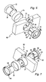
Figur 10- eine perspektivische Ansicht des am Mantelrohr befestigten Lenkstockmoduls gemäß Figur 6 und 7 und
- Figur 11
- eine Vorderansicht des Lenkstockmoduls gemäß
Figur 10.
- FIG. 1
- an exploded perspective view of a steering column module according to the invention,
- FIG. 2
- a cross section through the fastening device of the steering column module according to Figure 1 in a pre-assembly,
- FIG. 3
- the cross section of Figure 2 in the final assembly position,
- FIG. 4
- the front view of the steering column module according to Figure 1,
- FIG. 5
- a cross section through a circular wedge profile,
- FIG. 6
- an exploded perspective view of a second steering column module according to the invention,
- FIG. 7
- another view of the steering column module according to Figure 6,
- FIG. 8
- a cross section through the fastening means of the steering column module according to Figure 6 and 7,
- FIG. 9
- the clamping element of the fastening device of the steering column module according to Figure 6 and 7,
- FIG. 10
- a perspective view of the steering column module attached to the jacket tube according to Figure 6 and 7 and
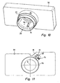
- FIG. 11
- a front view of the steering column module according to FIG. 10
In der Figur 1 ist ein erfindungsgemäßes Lenkstockmodul 10 mit einer erfindungsgemäßen Befestigungseinrichtung 12 dargestellt. Das Lenkstockmodul 10 nimmt nicht dargestellte Schalter auf, die mittels dargestellten Schalthebeln 14 betätigbar sind. Das Lenkstockschaltermodul 10 umfasst einen zentralen Durchbruch 16, in den das eine Ende einer Lenksäule 18 ragt. Dieses Ende der Lenksäule ist im montierten Zustand mit einem nicht dargestellten Lenkrad drehfest verbunden. Die Lenksäule 18 wird im Bereich des Lenkstockmoduls 10 von einem Mantelrohr 20 umgeben.FIG. 1 shows an inventive
Im oder am zentralen Durchbruch 16 kann ein Rotor einer Wickelfeder und/oder eines Lenkwinkelsensors drehbar gelagert angeordnet sein. Das Lenkstockmodul 10 weist einen Befestigungsabschnitt 22 zur Befestigung des Mantelrohrs 20 auf. Der Befestigungsabschnitt 22 wird auf der außenliegenden Seite von einem Metallring 24 umgeben. Zur Befestigung des Lenkstockmoduls 10 am Mantelrohr 20 wird der Befestigungsabschnitt 22 auf das freie Ende 26 des Mantelrohrs 20 aufgeschoben. Daran anschließend wird von der dem Mantelrohr abgewandten Seite 26 ein Klemmelement 28 zwischen das Mantelrohr 20 und den Befestigungsabschnitt 22 geschoben.In or on the
Aus dem in der Figur 2 gezeigten Querschnitt durch den Befestigungsabschnitt 22 des Lenkstockmoduls 10 wird deutlich, dass das Klemmelement auf der dem Befestigungsabschnitt 22 zugewandten radialen Außenseite drei identisch ausgebildete, gleichmäßig über den Umfang des Klemmelements 28 angeordnete Keilabschnitte 30 aufweist. Die drei Keilabschnitte 30 korrespondieren mit am Befestigungsabschnitt 22 vorgesehenen Gegenkeilabschnitten 32. Die Keilabschnitte 30 und die Gegenkeilabschnitte 32 sind komplementär zueinander ausgebildet. In der Vormontageposition, die in der Figur 2 dargestellt ist, können die Keilabschnitte 30 in axialer Richtung in die Gegenkeilabschnitte 32 eingeführt werden. Die Keilabschnitte 30 bzw. die Gegenkeilabschnitte 32 weisen Keilflächen 31 auf, die aus Segmenten von logarhythmischen Spiralen bestehen. Derartige Keilflächen sind in der Figur 5 exemplarisch an Kreiskeil-Profilen dargestellt.From the cross section shown in the figure 2 through the mounting
Die radial innenliegende Innenfläche 34 des Klemmelements 28 weist einen kreisrunden, das Mantelrohr 26 umgebenden Querschnitt auf. Der hülsenartig ausgebildete Befestigungsabschnitt 22 weist auf der radial außenliegenden, dem Klemmelement 28 abgewandten Außenseite 36 einen kreisrunden Querschnitt auf, der von dem Metallring 24 umgeben ist. Zur Befestigung des Lenkstockmoduls 10 am Mantelrohr 20 wird das Klemmelement 28 in dem in der Figur 2 dargestellten Querschnitt entgegen dem Uhrzeigersinn in die in der Figur 3 dargestellten Endmontagelage verdreht.The radially inner
Beim Verdrehen des Klemmelements 28 in die in der Figur 3 dargestellte Lage kommen die Keilflächen 31 der Keilabschnitte 30 und der Gegenkeilabschnitte 32 vollflächig zur gegenseitigen Anlage. Es wird eine großflächige, homogene Flächenpressung erzeugt. Die Keilsteigungen der Keilabschnitte 30, 32 sind so klein, dass eine Selbsthemmung auftritt. Folglich kann die Klemmverbindung auch in der Montagerichtung entgegengesetzter Richtung Momente übertragen. Aufgrund der gleichmäßig über den Umfang verteilten Anpresskräfte können außerdem axial wirkende Kräfte übertragen werden, wodurch eine zusätzliche Axialsicherung des Lenkstockmoduls 10 am Mantelrohr 12 entfallen kann. In der Endmontagestellung erhält man einen Querpressverband.When the clamping
Der Metallring 24 nimmt die radial wirkenden Kräfte auf und verhindert eine unerwünschte Deformierung des Befestigungsabschnitts 22.The
Das Mantelrohr 20 weist an seinem freien Ende 26 einen Längsschlitz 38 auf, der ein bedingt elastisches Nachgeben des Mantelrohrs 26 ermöglicht. Beim Verdrehen des Klemmelements 28 wirkt das Mantelrohr 20 aufgrund den auftretenden Radialkräften bedingt elastisch nachgiebig. Hierdurch ergibt sich eine gewisse Vorspannung.The
Zum Verdrehen des Keilelements weist das Keilelement 28 auf der radialen Außenseite einen Schraubenzahnabschnitt 40 auf, die in Figur 4 zu erkennen ist. Der Schraubenzahnabschnitt 40 wirkt mit einem Stellbolzen 42 zusammen. Der Stellbolzen 42 ist im montierten Zustand im Längsstockmodul 10 in einer Verdrehaufnahme 44 verdrehbar gelagert. Die Schraubenverzahnung 46 des Stellbolzens 42 steht in Eingriff mit dem Schraubenzahnabschnitt 40. Durch Verdrehen des Stellbolzens 42, beispielsweise mittels eines Schraubendrehers, wird über die Schraubenverzahnung 46 bzw. den Schraubenzahnabschnitt 40 das Klemmelement 28 verdreht.To rotate the wedge element, the
Aufgrund der drei gleichmäßig über den Querschnitt verteilt angeordneten Keilabschnitten 30, 32 wird bei der Befestigung des Lenkstockmoduls 10 am Mantelrohr 20 das Lenkstockmodul 10 in Bezug auf die Längsachse A selbst zentriert. Dadurch können zusätzliche Achsversatzausgleichsmittel eines im zentralen Durchbruch 16 drehbar gelagerten Wickelfeder- und/oder Drehwickelsensorrotors entfallen.Because of the three
Wie aus der Figur 1 deutlich wird, erstrecken sich die drei Keilabschnitte über weitgehend die gesamte Länge des Klemmelements 28. Dadurch wird einem Verkippen des Lenkstockmoduls 10 gegenüber dem Mantelrohr 20 entgegengewirkt.As is clear from FIG. 1, the three wedge sections extend over substantially the entire length of the clamping
Bei dem in der Figur dargestellten Ausführungsbeispiel wirkt das Klemmteil 28 einerseits unmittelbar gegen das Mantelrohr und andererseits unmittelbar gegen den Befestigungsabschnitt 22 des Lenkstockmoduls 10. Gemäß einer anderen Ausführungsform kann vorgesehen sein, dass zwischen dem Klemmteil 28 und dem Lenkstockmodul 10 bzw. dem Mantelrohr 20 Zwischenelemente, beispielsweise in Form von Hülsen, vorhanden sind.In the embodiment shown in the figure, the clamping
Die Figuren 6 bis 11 zeigen eine zweite erfindungsgemäße Ausführungsform. Den Figuren 1 bis 4 entsprechende Bauteile sind mit entsprechenden Bezugszeichen versehen.FIGS. 6 to 11 show a second embodiment according to the invention. Figures 1 to 4 corresponding components are provided with corresponding reference numerals.
Die in den Figuren 6 bis 11 dargestellte Befestigungseinrichtung 52 zur Befestigung des Lenkstockmoduls 50 am Mantelrohr 20 umfasst ein Klemmelement 54, das zwischen zwei benachbarten Keilabschnitten 56 zentrisch zur Längsachse verlaufende Kreissegmentabschnitte 58 aufweist. Die Keilflächen sind dabei im Querschnitt betrachtet, wie in Figur 8 dargestellt, nicht als Segmente logarhythmischer Spiralen, sondern als Kreissegmente ausgebildet. Die einzelnen Keilabschnitte schließen im Querschnitt gesehen, wie in Figur 8 dargestellt, einen Winkel β von ca. 30° ein. Die einzelnen Kreissegmentabschnitte 58 schließen einen Winkel α von ca. 90° ein.The
Die dem Klemmelement 54 zugewandte Seite des Befestigungsabschnitts 22 weist Gegenkeilabschnitte 60 auf, die ebenfalls eine kreissegmentförmige Oberfläche aufweisen. Der Radius dieser Oberflächen kann dem Radius der Keilabschnitte 56 entsprechen. Eine vorteilhafte Ausführungsform ergibt sich allerdings dann, wenn der Radius der Oberflächen der Gegenkeilabschnitte 60 verschieden von dem Radius der Keilabschnitte 56 ist.The clamping
Durch das Vorsehen von kreissegmentförmigen Keilflächen wird erreicht, dass eine Linienpressung zwischen den Keilabschnitten 56 und den Gegenkeilabschnitten 60 erreicht wird.The provision of circular segment-shaped wedge surfaces ensures that line pressure is achieved between the
In den Figuren 6 bis 9 ist zu erkennen, dass angrenzend an einen Keilabschnitt eine sich in Längsrichtung erstreckende nutartige Ausnehmung 62 im Klemmelement 54 vorgesehen ist. Da sich an jeden Keilabschnitt 56 eine Ausnehmung 62 anschließt, sind insgesamt drei Ausnehmungen 62 vorhanden. Die nutartigen Ausnehmungen 62 erstrecken sich auf der dem Mantelrohr 20 abgewandten Seite auch in Umfangsrichtung. Der Abschnitt der Ausnehmungen, der sich in Umfangsrichtung erstreckt, ist in den Figuren mit 64 gekennzeichnet. Durch Vorsehen der Ausnehmungen 62 und insbesondere des Abschnitts 64 wird eine gleichförmige Nachgiebigkeit der Keilabschnitte 56 in Richtung der Längsachse erreicht. Ein Anliegen entlang einer Linie, unter einer definierten Vorspannung, kann damit gewährleistet werden. Eine elastische Verformung der Keilabschnitte im Übergangsbereich von den Kreissegmentabschnitten 58 zu den Keilabschnitten 60 kann hierbei auftreten.In FIGS. 6 to 9 it can be seen that a longitudinally extending one adjacent to a wedge portion groove-
Durch die Nachgiebigkeit der Keilabschnitte in radialer Richtung wird gewährleistet, dass ein Beschädigen der Keilabschnitte auch bei zu weitem Verdrehen der Klemmelemente 54 nicht erfolgen kann. Eine Verdrehung kann beispielsweise bis an einen definierten Anschlag erfolgen.The flexibility of the wedge sections in the radial direction ensures that damage to the wedge sections can not take place even if the
Zur Verdrehung des Klemmelements 54 ist an dem Klemmelement 54 ein umlaufender Bund 66 mit einer Schraubenaufnahme 68 vorgesehen. Die Schraubenaufnahme 68 umfasst eine senkrecht zur Längsachse verlaufende Gewindebohrung 70, in die eine in der Figur 11 dargestellte Stellschraube 72 eingeschraubt werden kann. Im montierten Zustand stützt sich das freie Ende der Stellschraube 72 an einer Abstützung 74 des Lenkstockmoduls 50 ab. Durch Verdrehen der Schraube 72 bewegt sich die Schraubenaufnahme 68 derart, dass das Klemmelement 54 gegen das Lenkstockmodul 50 um seine Längsachse verdreht wird. Im Lenkstockmodul 50 ist eine Aussparung 76 vorgesehen, durch die die Stellschraube 72 zugänglich ist und verdreht werden kann.To rotate the clamping
Der Längsschlitz 38 im Mantelrohr 20 ist dafür vorgesehen, dass das Lenkstockmodul 50 in einer definierten Position montiert werden kann. Das Lenkstockmodul 50 sieht dazu einen Positionierzapfen 76 vor, der, wie in Figur 10 dargestellt, im montierten Zustand in den Längsschlitz 38 eingreift. Damit das Klemmelement 54 ohne Behinderung durch den Positionierzapfen 76 möglichst weit auf das freie Ende 26 des Mantelrohrs 20 aufgeschoben werden kann, weist es eine Ausnehmung 78 auf.The
Eine nicht dargestellte Ausführungsform der Erfindung kann vorsehen, dass die Verdrehmittel derart ausgebildet sind, dass beim axialen Einführen des Klemmelements in den zentralen Durchbruch 16 über entsprechende Führungsmittel ein Verdrehen des Klemmelements erfolgen kann. Beispielsweise können an dem Klemmelement Führungszapfen vorgesehen sein, die in an dem Befestigungsabschnitt vorgesehen Führungsbahnen eingreifen. Die Führungsbahnen können so ausgebildet sein, dass sie eine Zwangsverdrehung des Klemmelements bewirken, wenn dieses in axialer Richtung in den zentralen Durchbruch 16 eingeführt wird.A non-illustrated embodiment of the invention may provide that the torsion means are designed such that during axial insertion of the clamping element into the
Um die Endlage des Klemmelements 54 zu sichern, können entsprechende Sicherungsmittel vorgesehen sein. Derartige Sicherungsmittel können beispielsweise als Rast- oder Klemmelemente ausgebildet sein.In order to secure the end position of the clamping
Claims (24)
- A mounting device (12, 52) for mounting a steering column module (10) on the jacket tube (20) of a steering column, having a sleevelike clamping element (28, 54), which can be located between the jacket tube (20) and a mounting portion (22) of the steering column module (10) and which has wedge-shaped portions (30, 56) with wedge-shaped faces (31), extending at least largely parallel to the longitudinal axis, for wedge clamping upon rotation about the longitudinal axis.
- The mounting device (12, 52) as defined by claim 1, characterized in that the wedge-shaped portions (30, 56) are distributed at least largely identically and uniformly over the circumference of the clamping element (28, 54).
- The mounting device (12, 52) as defined by claim 1 or 2, characterized in that the clamping element (28, 54) and/or the jacket tube (20) has an at least partly open or closed cross section.
- The mounting device (12, 52) as defined by claim 1, 2 or 3, characterized in that the wedge-shaped portions (30) extend at least largely over the entire length of the clamping element (28, 54).
- The mounting device (12, 52) as defined by one of the foregoing claims, characterized in that the radially inner inside face (34) of the clamping element (28, 54) has a circular cross section.
- The mounting device (12, 52) as defined by one of the foregoing claims, characterized in that the wedge-shaped portions (30) are located on the radially outer outside face of the clamping element (28).
- The mounting device (12, 52) as defined by one of the foregoing claims, characterized in that the wedge-shaped portions (30, 56) correspond with at least largely complementary counterpart wedge-shaped portions (32, 60) located on the jacket tube (20) and on the mounting portion (22), respectively.
- The mounting device (12, 52) as defined by one of the foregoing claims, characterized in that the wedge-shaped faces (31) are embodied such that an at least largely homogeneous pressure per unit of surface area or linear pressure occurs.
- The mounting device (12, 52) as defined by one of the foregoing claims, characterized in that the wedge-shaped faces (31) have such a slight wedge slope that self-locking can occur.
- The mounting device (12, 52) as defined by one of the foregoing claims, characterized in that the wedge-shaped faces (31) are embodied in cross section as circular segments extending eccentrically to the longitudinal axis (A).
- The mounting device (12) as defined by one of the foregoing claims 1 through 9, characterized in that the wedge-shaped faces (31) are embodied in cross section as segments of logarithmic spirals.
- The mounting device (52) as defined by one of the foregoing claims, characterized in that the clamping element (54), between the wedge-shaped portions, has circular segment portions (58) extending centrally to the longitudinal axis.
- The mounting device (52) as defined by claim 12, characterized in that viewed in cross section, the circular segment portions (58) each form an angle (α) that is from 2.5 to 3.5 times larger than the angle (β) that the individual wedge-shaped portions (56) form.
- The mounting device (52) as defined by claim 12 or 13, characterized in that a circular segment portion (58) forms an angle (α) of 80° to 110°, and that a wedge-shaped portion (56) forms an angle (β) of 40° to 20°.
- The mounting device (52) as defined by one of the foregoing claims, characterized in that adjacent to a wedge- shaped portion (56), a groovelike recess (62) extending in the longitudinal direction is provided.
- The mounting device (52) as defined by claim 12 or 15, characterized in that the groovelike recess (62), on the side facing away from the jacket tube, extends in the circumferential direction (64).
- The mounting device (52) as defined by claim 16, characterized in that the recess (64) extends in the circumferential direction at least over the length of the wedge-shaped portion (56).
- The mounting device (12, 52) as defined by one of the foregoing claims, characterized in that the clamping element (28, 54) has twisting means (40, 58) on the radial outside, with which twisting of the clamping element (28, 54) can be enabled.
- The mounting device (12) as defined by claim 18, characterized in that the twisting means include a helical set of teeth (40), which is suitable for engagement with a counterpart set of teeth (46) of an adjusting bolt (42).
- The mounting device (12) as defined by claim 18, characterized in that the twisting means include a receptacle (68) for an adjusting screw (72), such that the adjusting screw is received perpendicular to the longitudinal axis (A), and upon twisting of the adjusting screw (72), the clamping element (54) is twisted relative to the steering column module (50) and to the jacket tube (20).
- The mounting device (12, 52) as defined by one of the foregoing claims, characterized in that the mounting portion (22), on the radially outer outside face (36), facing away from the clamping element, has a force-absorbing means (24) for receiving the radial forces that occur upon twisting of the clamping element (28).
- The mounting device (12) as defined by claim 21, characterized in that the outside (36) of the mounting portion is embodied as circular in cross section.
- The mounting device (12) as defined by claim 21 or 22, characterized in that the force-absorbing means is embodied as a metal ring (24) surrounding the outside (36).
- A steering column module (10), including a mounting device (12) as defined by one of the foregoing claims.
Applications Claiming Priority (4)
| Application Number | Priority Date | Filing Date | Title |
|---|---|---|---|
| DE10330481 | 2003-07-01 | ||
| DE2003130481 DE10330481A1 (en) | 2003-07-01 | 2003-07-01 | Fastening device for fastening a steering column assembly module on a steering column jacket has a sleeve-type clamping element to fit between a steering column jacket and a fastening section |
| DE10336302 | 2003-07-31 | ||
| DE10336302A DE10336302A1 (en) | 2003-07-01 | 2003-07-31 | Fastening device for fastening a steering column module to a steering column and steering column module |
Publications (2)
| Publication Number | Publication Date |
|---|---|
| EP1504964A1 EP1504964A1 (en) | 2005-02-09 |
| EP1504964B1 true EP1504964B1 (en) | 2006-07-05 |
Family
ID=33553482
Family Applications (1)
| Application Number | Title | Priority Date | Filing Date |
|---|---|---|---|
| EP04014208A Active EP1504964B1 (en) | 2003-07-01 | 2004-06-17 | Mounting device for fastening a steering column module on the steering column and a steering column module |
Country Status (3)
| Country | Link |
|---|---|
| EP (1) | EP1504964B1 (en) |
| AT (1) | ATE332252T1 (en) |
| DE (2) | DE10336302A1 (en) |
Families Citing this family (2)
| Publication number | Priority date | Publication date | Assignee | Title |
|---|---|---|---|---|
| FR2950850B1 (en) * | 2009-10-02 | 2012-01-13 | Renault Sa | SYSTEM FOR FASTENING A MODULE FOR HIGH COLUMN STEERING. |
| FR2977206A1 (en) * | 2011-06-29 | 2013-01-04 | Peugeot Citroen Automobiles Sa | Device for fixing secondary controls located under wheel emerging from casing of steering column of car, has screw jacks diving and inserting levers into corresponding openings and driven by bevel gear system, and gear rotated by shaft |
Family Cites Families (4)
| Publication number | Priority date | Publication date | Assignee | Title |
|---|---|---|---|---|
| FR2724696B1 (en) * | 1994-09-20 | 1997-01-24 | Magneti Marelli France | SYSTEM FOR FIXING AN ASSEMBLY ON A COLUMN, IN PARTICULAR FOR FIXING AN ELECTRICAL SWITCHING ASSEMBLY ON A STEERING COLUMN OF A MOTOR VEHICLE |
| FR2749354B1 (en) * | 1996-05-30 | 1998-08-07 | Valeo Electronique | SWITCH HOLDER WITH FIXING COLLAR FOR MOTOR VEHICLE |
| DE10051226A1 (en) * | 2000-10-16 | 2002-04-25 | Eaton Corp | Steering arm switch for motor vehicle has attachment device with clamping part that acts on casing tube and securing device for fixing central socket onto central plug |
| JP2002131047A (en) * | 2000-10-20 | 2002-05-09 | Niles Parts Co Ltd | Combination switch |
-
2003
- 2003-07-31 DE DE10336302A patent/DE10336302A1/en not_active Ceased
-
2004
- 2004-06-17 EP EP04014208A patent/EP1504964B1/en active Active
- 2004-06-17 AT AT04014208T patent/ATE332252T1/en not_active IP Right Cessation
- 2004-06-17 DE DE502004000907T patent/DE502004000907D1/en active Active
Also Published As
| Publication number | Publication date |
|---|---|
| ATE332252T1 (en) | 2006-07-15 |
| DE10336302A1 (en) | 2005-04-21 |
| EP1504964A1 (en) | 2005-02-09 |
| DE502004000907D1 (en) | 2006-08-17 |
Similar Documents
| Publication | Publication Date | Title |
|---|---|---|
| DE60017982T2 (en) | Electric power steering | |
| DE102016200102B4 (en) | Actuator, in particular for a rear axle steering of a motor vehicle | |
| WO2012022310A2 (en) | Device for pressing a toothed rack | |
| EP3717786B1 (en) | Tolerance compensation arrangement with safety clamp | |
| WO2004033834A1 (en) | Gearbox device, in particular for actuators in motor vehicles | |
| EP0770538A2 (en) | Rack and pinion gear | |
| DE102017209563A1 (en) | Floating bearing, steering gear and steering system | |
| DE102018204263A1 (en) | Spindle drive, method for producing a spindle drive and comfort drive | |
| EP2264327A1 (en) | System for connecting a shaft to a joint | |
| EP3700802A1 (en) | Prestressing device | |
| EP1504964B1 (en) | Mounting device for fastening a steering column module on the steering column and a steering column module | |
| WO2010081733A1 (en) | Drive for a component that can be adjusted | |
| EP1690024B1 (en) | Device for pressing on a rack | |
| DE102012021102A1 (en) | Strut for reinforcing motor vehicle, has screw bracket that is engaged into through hole formed in strut as round hole, so that bore of screw bracket is arranged eccentrically | |
| EP2659152B1 (en) | Drive unit with bearing device and adjustment drive | |
| DE102010039202A1 (en) | Rack and pinion steering for electrical steering system, particularly for motor vehicles, has rack which stands in interference with pinion and unit that is provided for pressing rack at pinion | |
| WO2019134814A1 (en) | Steering gear for a motor vehicle | |
| DE102005005400A1 (en) | Rack pressing device for rack and pinion steering, has set screw with external thread including recess that is running in axial direction of screw, and deformable material consisting of fiber inserted in to recess | |
| WO2017211513A1 (en) | Actuator for a rear axle steering | |
| DE102021209478A1 (en) | Belt retractor for a safety belt | |
| DE10330481A1 (en) | Fastening device for fastening a steering column assembly module on a steering column jacket has a sleeve-type clamping element to fit between a steering column jacket and a fastening section | |
| EP1439978B1 (en) | Gear drive unit provided with an adapter | |
| DE102015111258A1 (en) | STEERING GEAR AND METHOD FOR MOUNTING SUCH A STEERING GEAR | |
| DE19906693C1 (en) | Actuator, in particular for heating, ventilation or air conditioning flaps in a motor vehicle | |
| DE10231746A1 (en) | Gear drive unit with an adapter |
Legal Events
| Date | Code | Title | Description |
|---|---|---|---|
| PUAI | Public reference made under article 153(3) epc to a published international application that has entered the european phase |
Free format text: ORIGINAL CODE: 0009012 |
|
| AK | Designated contracting states |
Kind code of ref document: A1 Designated state(s): AT BE BG CH CY CZ DE DK EE ES FI FR GB GR HU IE IT LI LU MC NL PL PT RO SE SI SK TR |
|
| AX | Request for extension of the european patent |
Extension state: AL HR LT LV MK |
|
| 17P | Request for examination filed |
Effective date: 20050406 |
|
| AKX | Designation fees paid |
Designated state(s): AT BE BG CH CY CZ DE DK EE ES FI FR GB GR HU IE IT LI LU MC NL PL PT RO SE SI SK TR |
|
| GRAP | Despatch of communication of intention to grant a patent |
Free format text: ORIGINAL CODE: EPIDOSNIGR1 |
|
| GRAS | Grant fee paid |
Free format text: ORIGINAL CODE: EPIDOSNIGR3 |
|
| GRAA | (expected) grant |
Free format text: ORIGINAL CODE: 0009210 |
|
| RIN1 | Information on inventor provided before grant (corrected) |
Inventor name: HASCH, MARTIN Inventor name: GRUENER, ROLAND Inventor name: BINDER, BERND Inventor name: SIMONIS, KARL Inventor name: SUCHANEK, JUERGEN Inventor name: LIPFERT, RAINER |
|
| AK | Designated contracting states |
Kind code of ref document: B1 Designated state(s): AT BE BG CH CY CZ DE DK EE ES FI FR GB GR HU IE IT LI LU MC NL PL PT RO SE SI SK TR |
|
| PG25 | Lapsed in a contracting state [announced via postgrant information from national office to epo] |
Ref country code: PL Free format text: LAPSE BECAUSE OF FAILURE TO SUBMIT A TRANSLATION OF THE DESCRIPTION OR TO PAY THE FEE WITHIN THE PRESCRIBED TIME-LIMIT Effective date: 20060705 Ref country code: FI Free format text: LAPSE BECAUSE OF FAILURE TO SUBMIT A TRANSLATION OF THE DESCRIPTION OR TO PAY THE FEE WITHIN THE PRESCRIBED TIME-LIMIT Effective date: 20060705 Ref country code: CZ Free format text: LAPSE BECAUSE OF FAILURE TO SUBMIT A TRANSLATION OF THE DESCRIPTION OR TO PAY THE FEE WITHIN THE PRESCRIBED TIME-LIMIT Effective date: 20060705 Ref country code: IT Free format text: LAPSE BECAUSE OF FAILURE TO SUBMIT A TRANSLATION OF THE DESCRIPTION OR TO PAY THE FEE WITHIN THE PRESCRIBED TIME-LIMIT;WARNING: LAPSES OF ITALIAN PATENTS WITH EFFECTIVE DATE BEFORE 2007 MAY HAVE OCCURRED AT ANY TIME BEFORE 2007. THE CORRECT EFFECTIVE DATE MAY BE DIFFERENT FROM THE ONE RECORDED. Effective date: 20060705 Ref country code: NL Free format text: LAPSE BECAUSE OF FAILURE TO SUBMIT A TRANSLATION OF THE DESCRIPTION OR TO PAY THE FEE WITHIN THE PRESCRIBED TIME-LIMIT Effective date: 20060705 Ref country code: GB Free format text: LAPSE BECAUSE OF FAILURE TO SUBMIT A TRANSLATION OF THE DESCRIPTION OR TO PAY THE FEE WITHIN THE PRESCRIBED TIME-LIMIT Effective date: 20060705 Ref country code: IE Free format text: LAPSE BECAUSE OF FAILURE TO SUBMIT A TRANSLATION OF THE DESCRIPTION OR TO PAY THE FEE WITHIN THE PRESCRIBED TIME-LIMIT Effective date: 20060705 Ref country code: RO Free format text: LAPSE BECAUSE OF FAILURE TO SUBMIT A TRANSLATION OF THE DESCRIPTION OR TO PAY THE FEE WITHIN THE PRESCRIBED TIME-LIMIT Effective date: 20060705 Ref country code: SK Free format text: LAPSE BECAUSE OF FAILURE TO SUBMIT A TRANSLATION OF THE DESCRIPTION OR TO PAY THE FEE WITHIN THE PRESCRIBED TIME-LIMIT Effective date: 20060705 Ref country code: SI Free format text: LAPSE BECAUSE OF FAILURE TO SUBMIT A TRANSLATION OF THE DESCRIPTION OR TO PAY THE FEE WITHIN THE PRESCRIBED TIME-LIMIT Effective date: 20060705 |
|
| REG | Reference to a national code |
Ref country code: GB Ref legal event code: FG4D Free format text: NOT ENGLISH |
|
| REG | Reference to a national code |
Ref country code: CH Ref legal event code: EP |
|
| REG | Reference to a national code |
Ref country code: IE Ref legal event code: FG4D Free format text: LANGUAGE OF EP DOCUMENT: GERMAN |
|
| REF | Corresponds to: |
Ref document number: 502004000907 Country of ref document: DE Date of ref document: 20060817 Kind code of ref document: P |
|
| PG25 | Lapsed in a contracting state [announced via postgrant information from national office to epo] |
Ref country code: DK Free format text: LAPSE BECAUSE OF FAILURE TO SUBMIT A TRANSLATION OF THE DESCRIPTION OR TO PAY THE FEE WITHIN THE PRESCRIBED TIME-LIMIT Effective date: 20061005 Ref country code: BG Free format text: LAPSE BECAUSE OF FAILURE TO SUBMIT A TRANSLATION OF THE DESCRIPTION OR TO PAY THE FEE WITHIN THE PRESCRIBED TIME-LIMIT Effective date: 20061005 Ref country code: SE Free format text: LAPSE BECAUSE OF FAILURE TO SUBMIT A TRANSLATION OF THE DESCRIPTION OR TO PAY THE FEE WITHIN THE PRESCRIBED TIME-LIMIT Effective date: 20061005 |
|
| PG25 | Lapsed in a contracting state [announced via postgrant information from national office to epo] |
Ref country code: ES Free format text: LAPSE BECAUSE OF FAILURE TO SUBMIT A TRANSLATION OF THE DESCRIPTION OR TO PAY THE FEE WITHIN THE PRESCRIBED TIME-LIMIT Effective date: 20061016 |
|
| NLV1 | Nl: lapsed or annulled due to failure to fulfill the requirements of art. 29p and 29m of the patents act | ||
| PG25 | Lapsed in a contracting state [announced via postgrant information from national office to epo] |
Ref country code: PT Free format text: LAPSE BECAUSE OF FAILURE TO SUBMIT A TRANSLATION OF THE DESCRIPTION OR TO PAY THE FEE WITHIN THE PRESCRIBED TIME-LIMIT Effective date: 20061205 |
|
| GBV | Gb: ep patent (uk) treated as always having been void in accordance with gb section 77(7)/1977 [no translation filed] |
Effective date: 20060705 |
|
| ET | Fr: translation filed | ||
| REG | Reference to a national code |
Ref country code: IE Ref legal event code: FD4D |
|
| PLBE | No opposition filed within time limit |
Free format text: ORIGINAL CODE: 0009261 |
|
| STAA | Information on the status of an ep patent application or granted ep patent |
Free format text: STATUS: NO OPPOSITION FILED WITHIN TIME LIMIT |
|
| 26N | No opposition filed |
Effective date: 20070410 |
|
| BERE | Be: lapsed |
Owner name: VALEO SCHALTER UND SENSOREN G.M.B.H. Effective date: 20070630 |
|
| PG25 | Lapsed in a contracting state [announced via postgrant information from national office to epo] |
Ref country code: MC Free format text: LAPSE BECAUSE OF NON-PAYMENT OF DUE FEES Effective date: 20070630 |
|
| PG25 | Lapsed in a contracting state [announced via postgrant information from national office to epo] |
Ref country code: BE Free format text: LAPSE BECAUSE OF NON-PAYMENT OF DUE FEES Effective date: 20070630 |
|
| PG25 | Lapsed in a contracting state [announced via postgrant information from national office to epo] |
Ref country code: GR Free format text: LAPSE BECAUSE OF FAILURE TO SUBMIT A TRANSLATION OF THE DESCRIPTION OR TO PAY THE FEE WITHIN THE PRESCRIBED TIME-LIMIT Effective date: 20061006 |
|
| PG25 | Lapsed in a contracting state [announced via postgrant information from national office to epo] |
Ref country code: EE Free format text: LAPSE BECAUSE OF FAILURE TO SUBMIT A TRANSLATION OF THE DESCRIPTION OR TO PAY THE FEE WITHIN THE PRESCRIBED TIME-LIMIT Effective date: 20060705 |
|
| PG25 | Lapsed in a contracting state [announced via postgrant information from national office to epo] |
Ref country code: AT Free format text: LAPSE BECAUSE OF NON-PAYMENT OF DUE FEES Effective date: 20070617 |
|
| REG | Reference to a national code |
Ref country code: CH Ref legal event code: PL |
|
| PG25 | Lapsed in a contracting state [announced via postgrant information from national office to epo] |
Ref country code: CH Free format text: LAPSE BECAUSE OF NON-PAYMENT OF DUE FEES Effective date: 20080630 Ref country code: LI Free format text: LAPSE BECAUSE OF NON-PAYMENT OF DUE FEES Effective date: 20080630 |
|
| PG25 | Lapsed in a contracting state [announced via postgrant information from national office to epo] |
Ref country code: CY Free format text: LAPSE BECAUSE OF FAILURE TO SUBMIT A TRANSLATION OF THE DESCRIPTION OR TO PAY THE FEE WITHIN THE PRESCRIBED TIME-LIMIT Effective date: 20060705 Ref country code: LU Free format text: LAPSE BECAUSE OF NON-PAYMENT OF DUE FEES Effective date: 20070617 |
|
| PG25 | Lapsed in a contracting state [announced via postgrant information from national office to epo] |
Ref country code: TR Free format text: LAPSE BECAUSE OF FAILURE TO SUBMIT A TRANSLATION OF THE DESCRIPTION OR TO PAY THE FEE WITHIN THE PRESCRIBED TIME-LIMIT Effective date: 20060705 Ref country code: HU Free format text: LAPSE BECAUSE OF FAILURE TO SUBMIT A TRANSLATION OF THE DESCRIPTION OR TO PAY THE FEE WITHIN THE PRESCRIBED TIME-LIMIT Effective date: 20070106 |
|
| REG | Reference to a national code |
Ref country code: FR Ref legal event code: PLFP Year of fee payment: 13 |
|
| REG | Reference to a national code |
Ref country code: FR Ref legal event code: PLFP Year of fee payment: 14 |
|
| REG | Reference to a national code |
Ref country code: FR Ref legal event code: PLFP Year of fee payment: 15 |
|
| PGFP | Annual fee paid to national office [announced via postgrant information from national office to epo] |
Ref country code: FR Payment date: 20180627 Year of fee payment: 15 |
|
| PG25 | Lapsed in a contracting state [announced via postgrant information from national office to epo] |
Ref country code: FR Free format text: LAPSE BECAUSE OF NON-PAYMENT OF DUE FEES Effective date: 20190630 |
|
| P01 | Opt-out of the competence of the unified patent court (upc) registered |
Effective date: 20230528 |
|
| PGFP | Annual fee paid to national office [announced via postgrant information from national office to epo] |
Ref country code: DE Payment date: 20230613 Year of fee payment: 20 |