EP1504644B1 - Schleuderdüngerstreuer - Google Patents
Schleuderdüngerstreuer Download PDFInfo
- Publication number
- EP1504644B1 EP1504644B1 EP04018253A EP04018253A EP1504644B1 EP 1504644 B1 EP1504644 B1 EP 1504644B1 EP 04018253 A EP04018253 A EP 04018253A EP 04018253 A EP04018253 A EP 04018253A EP 1504644 B1 EP1504644 B1 EP 1504644B1
- Authority
- EP
- European Patent Office
- Prior art keywords
- centrifugal
- ladder member
- protective
- ladder
- conductor element
- Prior art date
- Legal status (The legal status is an assumption and is not a legal conclusion. Google has not performed a legal analysis and makes no representation as to the accuracy of the status listed.)
- Expired - Lifetime
Links
Images


Classifications
-
- E—FIXED CONSTRUCTIONS
- E06—DOORS, WINDOWS, SHUTTERS, OR ROLLER BLINDS IN GENERAL; LADDERS
- E06C—LADDERS
- E06C5/00—Ladders characterised by being mounted on undercarriages or vehicles Securing ladders on vehicles
- E06C5/02—Ladders characterised by being mounted on undercarriages or vehicles Securing ladders on vehicles with rigid longitudinal members
-
- A—HUMAN NECESSITIES
- A01—AGRICULTURE; FORESTRY; ANIMAL HUSBANDRY; HUNTING; TRAPPING; FISHING
- A01C—PLANTING; SOWING; FERTILISING
- A01C15/00—Fertiliser distributors
- A01C15/003—Bulk fertiliser or grain handling in the field or on the farm
-
- A—HUMAN NECESSITIES
- A01—AGRICULTURE; FORESTRY; ANIMAL HUSBANDRY; HUNTING; TRAPPING; FISHING
- A01C—PLANTING; SOWING; FERTILISING
- A01C15/00—Fertiliser distributors
- A01C15/005—Undercarriages, tanks, hoppers, stirrers specially adapted for seeders or fertiliser distributors
-
- A—HUMAN NECESSITIES
- A01—AGRICULTURE; FORESTRY; ANIMAL HUSBANDRY; HUNTING; TRAPPING; FISHING
- A01C—PLANTING; SOWING; FERTILISING
- A01C17/00—Fertilisers or seeders with centrifugal wheels
- A01C17/001—Centrifugal throwing devices with a vertical axis
Definitions
- the invention relates to a centrifugal fertilizer spreader according to the preamble of claim 1.
- the protective guard provided there can be folded away into a position so that it can serve as a step for the operator.
- bracket parts can be arranged on the guard, so that a kind of "ladder" is created. These additional bracket parts run parallel to the guard. By this the treads forming additional bow parts results in a large extension of the guard.
- the invention has for its object to achieve an advantageous attachment of a conductor element to a centrifugal fertilizer spreader with a comfortable ascent possibility on the conductor element.
- the conductor element has a plurality of ladder rungs, that the conductor element from a lying protective position in an upright rise position and vice versa can be brought.
- a compact conductor element which serves as a protective element in the lying protective position and in the upright rise position exercises the ladder function.
- the ladder can be climbed comfortably and safely in the upright position. Due to this novel design of the conductor element, the conductor element assumes both the protective function and the conductor function.
- the conductor element is arranged rotatably about an axis of rotation pointing in the direction of travel of the spreader. This allows the conductor element very easily bring in the two intended positions.
- the axis of rotation of the conductor element is slightly inclined obliquely forward down.
- the conductor element can be fixed and / or locked in the protective and in the ascent position by means of locking means.
- a simple arrangement is achieved in that the conductor element is arranged by means of a rotary joint on the frame.
- the conductor element can be suspended by means of suitable means either in the protective position or in the rise position on the spreader.
- the conductor element can be connected in its protective position with the carrier elements of the illumination device. As a result of these measures, the conductor element can be attached to already existing on the spreader carrier element in the protective position.
- means which switch off the drive of the centrifugal discs when removing the conductor element from the protective position.
- the same integrated protection function can be achieved in that means are provided which lock the conductor element forcibly when not switched off drive the centrifugal discs in the protective position.
- FIG. 1 and 2 show a centrifugal fertilizer spreader with reservoir 1 and frame 2. Below the outlet funnel 3 of the reservoir 1, which are completed by metering 4, rotating driven centrifugal discs 5 are arranged. On the spreader is a protective element 6, which is seen in plan view outside the outer parts 7 of the centrifugal discs 5, is arranged. In some areas, the protective element 6 is designed as a conductor element 8.
- the conductor element 8 has a plurality of ladder rungs 9, which extend perpendicular to itself in the protective position conductor element 8, as shown in Fig. 1.
- the conductor element 8 can be brought to the upright rise position shown in Fig. 2 on the spreader.
- the conductor element 8 is suspended on the carrier elements 1 of the illumination device 10 by means of suspension elements 11 attached thereto.
- the conductor element 8 is mounted on the arranged on the frame 2 and the reservoir 1 suspension elements 12.
- the conductor element 13 is arranged by means of a rotary joint 14 via connecting elements 15 on the storage container 1.
- locking means 16 the conductor element 13 is locked in the protective position in the illustrated lying position.
- the locking elements 16 are brought into unlocked position, so that the conductor element 13 about the rotation axis 17, which extends in the direction of travel 18, can be rotated in the upright rise position. In this Ascent position, the conductor element 13 is then locked by means of the locking element 18.
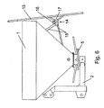
- the embodiment according to FIGS. 5 and 6 differs from the exemplary embodiment according to FIGS. 3 and 4 in that the axis of rotation 19 around which the conductor element 13 is rotatable extends from the rear-up obliquely forwards-down, so that the conductor element 13 which is slightly inclined from the vertical in the direction of the spreader shown in Fig. 6 assumes "ajar" position. In this slightly inclined from the vertical position a pleasant climb on the conductor element 13 is possible.
- the conductor elements 8 and 13 may be associated with means, not shown, which forcibly lock the conductor element 8 or 13 with non-disengaged drive the centrifugal discs in the protective position by means suitable means.
Landscapes
- Life Sciences & Earth Sciences (AREA)
- Soil Sciences (AREA)
- Environmental Sciences (AREA)
- Engineering & Computer Science (AREA)
- Mechanical Engineering (AREA)
- Fertilizing (AREA)
Description
- Die Erfindung betrifft einen Schleuderdüngerstreuer gemäß des Oberbegriffes des Patentanspruches 1.
- Ein derartiger Schleuderdüngerstreuer ist beispielsweise in der EP 0 501 202 A1 beschrieben. Gemäß einer Ausführungsform kann der dort vorgesehene Schutzbügel in eine Position weggeklappt werden, so dass der als Trittstufe für die Bedienungsperson dienen kann. Zusätzlich können Bügelteile an dem Schutzbügel angeordnet werden, so dass eine Art "Leiter" geschaffen wird. Diese zusätzlichen Bügelteile verlaufen parallel zu dem Schutzbügel. Durch diese die Trittstufen bildenden zusätzlichen Bügelteile ergibt sich eine große Ausdehnung des Schutzbügels.
- Der Erfindung liegt die Aufgabe zugrunde, eine vorteilhafte Anbringung eines Leiterelementes an einem Schleuderdüngerstreuer mit einer bequemen Aufstiegsmöglichkeit auf dem Leiterelement zu erreichen.
- Diese Aufgabe wird erfindungsgemäß dadurch gelöst, dass das Leiterelement mehrere Leitersprossen aufweist, dass das Leiterelement aus einer liegenden Schutzposition in eine aufrechte Aufstiegsposition und umgekehrt bringbar ist.
- Infolge dieser Maßnahme wird ein kompaktes Leiterelement geschaffen, welches in der liegenden Schutzposition als Schutzelement dient und in der aufrechten Aufstiegsposition die Leiterfunktion ausübt. Somit kann die Leiter in der aufrechten Stellung bequem und sicher bestiegen werden. Durch diese neuartige Ausgestaltung des Leiterelementes übernimmt das Leiterelement sowohl die Schutzfunktion als auch die Leiterfunktion.
- In einer Ausführungsform ist vorgesehen, dass das Leiterelement um eine in Fahrtrichtung des Streuers weisende Drehachse verdrehbar angeordnet ist. Hierdurch lässt sich das Leiterelement sehr leicht in die beiden vorgesehenen Positionen bringen. Um einen äußerst vorteilhaften Aufstieg auf dem Leiterelement zu ermöglichen, so dass die Leiter geneigt angeordnet ist, ist vorgesehen, dass die Drehachse des Leiterelementes geringfügig nach schräg vorn unten geneigt ist. Um eine sichere Anordnung des Leiterelementes in der jeweiligen Position zu gewährleisten, ist vorgesehen, das Leiterelement in der Schutz- und in der Aufstiegsposition jeweils mittels Verriegelungsmittel festsetz- und/oder verriegelbar ist.
- Eine einfache Anordnung wird dadurch erreicht, dass das Leiterelement mittels eines Drehgelenkes am Rahmen angeordnet ist.
- In einer anderen Ausgestaltung ist vorgesehen, das Leiterelement mittels geeigneter Mittel wahlweise in die Schutzposition oder in die Aufstiegsposition an dem Streuer einhängbar ist.
- In einer weiteren Ausgestaltung ist vorgesehen, dass das Leiterelement in seiner Schutzposition mit den Trägerelementen der Beleuchtungseinrichtung verbindbar ist. Infolge dieser Maßnahmen kann das Leiterelement an bereits am Streuer vorhandenen Trägerelement in die Schutzposition angebracht werden.
- Um in den Schutzbügel eine integrierte Sicherheitsfunktion an zu zuweisen, sind Mittel vorhanden, die bei Entfernen des Leiterelementes aus der Schutzposition den Antrieb der Schleuderscheiben abschalten.
- Die gleiche integrierte Schutzfunktion kann dadurch erreicht werden, dass Mittel vorhanden sind, die bei nicht abgeschaltetem Antrieb der Schleuderscheiben in der Schutzposition zwangsweise das Leiterelement verriegeln.
- Weitere Einzelheiten der Erfindung sind den übrigen Unteransprüchen, der Beispielsbeschreibung und den Zeichnungen zu entnehmen.
- Hierbei zeigen:
- Fig. 1
- den Düngerstreuer mit sich in Schutzposition befindlichen Leiterelement in der Ansicht von hinten und in Prinzipdarstellung,
- Fig. 2
- den Düngerstreuer nach Fig. 1, wobei das Leiterelement in Aufstiegsposition angeordnet ist.
- Fig. 3
- den Schleuderdüngerstreuer mit sich in Schutzposition befindlichen Leiterelement in Seitenansicht und Prinzipdarstellung,
- Fig. 4
- den Schleuderdüngerstreuer gemäß Fig. 3 jedoch sich in Aufstiegsposition befindlichen Leiterelement,
- Fig. 5
- einen weiteren Düngerstreuer mit sich in Schutzposition befindlichen Leiterelement in Seitenansicht und Prinzipdarstellung und
- Fig. 6
- den Schleuderdüngerstreuer gemäß Fig. 5 jedoch mit sich in Aufstiegsposition befindlichen Leiterelement.
- Die Fig. 1 und 2 zeigen einen Schleuderdüngerstreuer mit Vorratsbehälter 1 und Rahmen 2. Unterhalb der Auslauftrichter 3 des Vorratsbehälters 1, die durch Dosierelemente 4 abgeschlossen sind, sind rotierend angetriebene Schleuderscheiben 5 angeordnet. An dem Streuer ist ein Schutzelement 6, welches in Draufsicht gesehen außerhalb der äußeren Teile 7 der Schleuderscheiben 5 sich befindet, angeordnet. In Teilbereichen ist das Schutzelement 6 als Leiterelement 8 ausgebildet. Das Leiterelement 8 weist mehrere Leitersprossen 9 auf, die bei sich in Schutzposition befindlichen Leiterelement 8 senkrecht verlaufen, wie in Fig. 1 dargestellt.
- Das Leiterelement 8 kann die in Fig. 2 dargestellte aufrechte Aufstiegsposition an dem Streuer gebracht werden. In der Schutzfunktion ist das Leiterelement 8 an den Trägerelementen 1 der Beleuchtungseinrichtung 10 mittels an diesen angebrachten Einhängelementen 11 eingehängt. In der in Fig. 2 dargestellten Schutzposition ist das Leiterelement 8 an den am Rahmen 2 und am Vorratsbehälter 1 angeordneten Einhängelementen 12 eingehängt.
- Bei dem Ausführungsbeispiel nach den Fig. 3 und 4 ist das Leiterelement 13 mittels eines Drehgelenkes 14 über Verbindungselemente 15 am Vorratsbehälter 1 angeordnet. Mittels nicht näher dargestellter Verriegelungsmittel 16 wird das Leiterelement 13 in der Schutzposition in der dargestellten liegenden Position verriegelt. Um das Leiterelement 13 in die in Fig. 4 dargestellte aufrechte Aufstiegsposition zu bringen, werden die Verriegelungselemente 16 in nicht entriegelter Stellung gebracht, so dass das Leiterelement 13 um die Drehachse 17, die in Fahrtrichtung 18 verläuft, in die aufrechte Aufstiegsposition gedreht werden kann. In dieser Aufstiegsposition wird das Leiterelement 13 dann mittels des Verriegelungselementes 18 verriegelt.
- Das Ausführungsbeispiel gemäß den Fig. 5 und 6 unterscheidet sich von dem Ausführungsbeispiel gemäß Fig. 3 und 4 dadurch, dass die Drehachse 19 um welche das Leiterelement 13 verdrehbar ist, von hinten - oben schräg nach vorn - unten verläuft, so dass das Leiterelement 13 die in Fig. 6 dargestellte leicht von der senkrechten in Richtung des Streuers geneigte "angelehnte" Position einnimmt. In dieser leicht aus der senkrechten geneigten Position ist ein angenehmer Aufstieg auf dem Leiterelement 13 möglich.
- Den Leiterelementen 8 und 13 können nicht dargestellte Mittel zugeordnet sein, die das Leiterelement 8 oder 13 bei nicht abgeschalteten Antrieb der Schleuderscheiben in der Schutzposition mittels geeigneter Mittel zwangsweise verriegeln.
- Weiterhin können nicht dargestellte Mittel vorhanden sein, die beim Entfernen des Leiterelementes 8 oder 13 aus der Schutzposition den Antrieb der Schleuderscheiben mittels geeigneter Mittel abschalten.
Claims (10)
- Schleuderdüngerstreuer mit einem Rahmen und Vorratsbehälter, unter dem angetriebene Schleuderscheiben angeordnet sind, wobei ein Schutzelement, beispielsweise ein Schutzbügel vorgesehen ist, welcher sich in Draufsicht gesehen außerhalb der äußeren Teile der Schleuderscheiben befindet und in Teilbereichen als Leiterelement ausgebildet ist, dadurch gekennzeichnet, dass das Leiterelement (8, 13) mehrere Leitersprossen (9) aufweist, dass das Leiterelement (8, 13) aus einer liegenden Schutzposition in eine aufrechte Aufstiegsposition und umgekehrt bringbar ist.
- Schleuderdüngerstreuer nach Anspruch 1, dadurch gekennzeichnet, dass das Leiterelement (13) um eine in Fahrtrichtung (18) des Streuers weisende Drehachse (17, 19) verdrehbar angeordnet ist.
- Schleuderdüngerstreuer nach einem oder mehreren der vorstehenden Ansprüche, dadurch gekennzeichnet, dass die Drehachse (19) des Leiterelementes (13) geringfügig nach schräg vorn unten geneigt ist.
- Schleuderdüngerstreuer nach einem oder mehreren der vorstehenden Ansprüche, dadurch gekennzeichnet, dass das Leiterelement (8, 13) in der Schutz- und in der Aufstiegsposition jeweils mittels Verriegelungsmittel (11, 12, 16) festsetz- und/oder verriegelbar ist.
- Schleuderdüngerstreuer nach einem oder mehreren der vorstehenden Ansprüche, dadurch gekennzeichnet, dass das Leiterelement mittels eines Drehgelenkes (14) am Rahmen angeordnet ist.
- Schleuderdüngerstreuer nach Anspruch 1, dadurch gekennzeichnet, dass das Leiterelement (8) mittels geeigneter Mittel (11, 12) wahlweise in die Schutzposition oder in die Aufstiegsposition an dem Streuer einhängbar ist.
- Schleuderdüngerstreuer nach Anspruch 6, dadurch gekennzeichnet, dass die Einhängmittel (12) am Rahmen (2) und/oder am Vorratsbehälter (1) angeordnet sind.
- Schleuderdüngerstreuer nach einem oder mehreren der vorstehenden Ansprüche, dadurch gekennzeichnet, dass an dem Streuer eine Trägerelemente (11) aufweisende Beleuchtungseinrichtung (10) angeordnet ist, dass das Leiterelement in seiner Schutzposition mit den Trägerelementen (11) der Beleuchtungseinrichtung verbindbar ist.
- Schleuderdüngerstreuer nach einem oder mehreren der vorstehenden Ansprüche, dadurch gekennzeichnet, dass Mittel vorhanden sind, die bei Entfernen des Leiterelementes (8, 13) aus der Schutzposition den Antrieb der Schleuderscheiben abschalten.
- Schleuderdüngerstreuer nach Anspruch 1, dadurch gekennzeichnet, dass Mittel vorhanden sind, die das Leiterelement (8, 13) bei nicht abgeschalteten Antrieb der Schleuderscheiben in der Schutzposition zwangsweise verriegeln.
Priority Applications (1)
| Application Number | Priority Date | Filing Date | Title |
|---|---|---|---|
| PL04018253T PL1504644T3 (pl) | 2003-08-05 | 2004-08-02 | Odśrodkowy rozsiewacz nawozów |
Applications Claiming Priority (2)
| Application Number | Priority Date | Filing Date | Title |
|---|---|---|---|
| DE10335765A DE10335765A1 (de) | 2003-08-05 | 2003-08-05 | Schleuderdüngerstreuer |
| DE10335765 | 2003-08-05 |
Publications (2)
| Publication Number | Publication Date |
|---|---|
| EP1504644A1 EP1504644A1 (de) | 2005-02-09 |
| EP1504644B1 true EP1504644B1 (de) | 2007-03-21 |
Family
ID=33547080
Family Applications (1)
| Application Number | Title | Priority Date | Filing Date |
|---|---|---|---|
| EP04018253A Expired - Lifetime EP1504644B1 (de) | 2003-08-05 | 2004-08-02 | Schleuderdüngerstreuer |
Country Status (5)
| Country | Link |
|---|---|
| EP (1) | EP1504644B1 (de) |
| AT (1) | ATE357129T1 (de) |
| DE (2) | DE10335765A1 (de) |
| DK (1) | DK1504644T3 (de) |
| PL (1) | PL1504644T3 (de) |
Cited By (2)
| Publication number | Priority date | Publication date | Assignee | Title |
|---|---|---|---|---|
| DE102009009280A1 (de) | 2009-02-17 | 2010-08-19 | Amazonen-Werke H. Dreyer Gmbh & Co. Kg | Schleuderstreuer |
| EP2364583A1 (de) | 2010-03-09 | 2011-09-14 | Amazonen-Werke H. Dreyer GmbH & Co. KG | Landwirtschaftliche Verteilmaschine |
Families Citing this family (5)
| Publication number | Priority date | Publication date | Assignee | Title |
|---|---|---|---|---|
| DE102008056208A1 (de) * | 2008-11-06 | 2010-05-12 | Rauch Landmaschinenfabrik Gmbh | Scheibendüngerstreuer |
| DE102009044743B4 (de) | 2009-12-03 | 2024-06-13 | Amazonen-Werke H. Dreyer SE & Co. KG | Schleuderstreuer mit Schutzbügel als Leitersprosse |
| DE102012107429A1 (de) * | 2012-08-14 | 2014-05-15 | Amazonen-Werke H. Dreyer Gmbh & Co. Kg | Schleuderstreuer |
| CN105804632B (zh) * | 2016-05-13 | 2017-08-25 | 崔会梓 | 一种起重机上可调高度的爬梯 |
| RU188930U1 (ru) * | 2019-01-25 | 2019-04-29 | Федеральное государственное бюджетное образовательное учреждение высшего образования "Донской государственный аграрный университет" (ФГБОУ ВО Донской ГАУ) | Разбрасыватель минеральных и концентрированных органических удобрений |
Family Cites Families (5)
| Publication number | Priority date | Publication date | Assignee | Title |
|---|---|---|---|---|
| US3063723A (en) * | 1958-04-03 | 1962-11-13 | Howard L Toft | Broadcast spreader |
| DE69022231T2 (de) * | 1990-02-26 | 1996-05-09 | Whiting Roll Up Door Mfg Corp | Drehbare leiter. |
| DE4109846A1 (de) | 1991-02-23 | 1992-11-05 | Amazonen Werke Dreyer H | Schleuderduengerstreuer |
| FR2683698B1 (fr) * | 1991-11-20 | 1994-11-18 | Rauch Landmaschinenfabrik Gmbh | Epandeur centrifuge pour epandre du produit granule. |
| DE19607618A1 (de) * | 1996-02-29 | 1997-09-04 | Rauch Landmaschfab Gmbh | Sämaschine |
-
2003
- 2003-08-05 DE DE10335765A patent/DE10335765A1/de not_active Withdrawn
-
2004
- 2004-08-02 DK DK04018253T patent/DK1504644T3/da active
- 2004-08-02 DE DE502004003256T patent/DE502004003256D1/de not_active Expired - Lifetime
- 2004-08-02 PL PL04018253T patent/PL1504644T3/pl unknown
- 2004-08-02 AT AT04018253T patent/ATE357129T1/de not_active IP Right Cessation
- 2004-08-02 EP EP04018253A patent/EP1504644B1/de not_active Expired - Lifetime
Cited By (3)
| Publication number | Priority date | Publication date | Assignee | Title |
|---|---|---|---|---|
| DE102009009280A1 (de) | 2009-02-17 | 2010-08-19 | Amazonen-Werke H. Dreyer Gmbh & Co. Kg | Schleuderstreuer |
| EP2364583A1 (de) | 2010-03-09 | 2011-09-14 | Amazonen-Werke H. Dreyer GmbH & Co. KG | Landwirtschaftliche Verteilmaschine |
| DE102010015863A1 (de) | 2010-03-09 | 2011-09-15 | Amazonen-Werke H. Dreyer Gmbh & Co. Kg | Landwirtschaftliche Verteilmaschine |
Also Published As
| Publication number | Publication date |
|---|---|
| ATE357129T1 (de) | 2007-04-15 |
| EP1504644A1 (de) | 2005-02-09 |
| DK1504644T3 (da) | 2007-04-23 |
| DE10335765A1 (de) | 2005-03-03 |
| DE502004003256D1 (de) | 2007-05-03 |
| PL1504644T3 (pl) | 2007-05-31 |
Similar Documents
| Publication | Publication Date | Title |
|---|---|---|
| DE112005002378T5 (de) | Zurückziehbare Zugangssystemleiter und Arbeitsmaschine, die diese verwendet | |
| EP2616595B1 (de) | Absturzsicherung für eine schachtöffnung | |
| EP3047888A1 (de) | Spielfahrzeug - bagger | |
| EP1504644A1 (de) | Schleuderdüngerstreuer | |
| DE19620072C2 (de) | Aufstiege für ein landwirtschaftliches Trägerfahrzeug | |
| DE602004000067T2 (de) | Kraftfahrzeug mit ausklappbaren Trittstufen | |
| DE60318350T2 (de) | Schutzgeländervorrichtung | |
| WO2018059915A1 (de) | Staubhaube für ein schleifgerät | |
| DE10207408C1 (de) | Vorrichtung für die zeitweilige geschützte Halterung einer unteren Scheibe der Fahrerkabine eines schweren Geräts in der Fahrerkabine | |
| EP0501202B1 (de) | Schleuderdüngerstreuer | |
| DE202009015105U1 (de) | Hoflader mit Rückhaltevorrichtung | |
| EP2364583B1 (de) | Landwirtschaftliche Verteilmaschine | |
| DE10213034B4 (de) | Vorrichtung zum Schutz vor Verletzungen | |
| DE2849142A1 (de) | Vorrichtung zum anheben des ersatzrades von fahrzeugen, insbesondere von industrie- und lieferfahrzeugen | |
| DE3125110A1 (de) | "schuettgutbunker-austragvorrichtung" | |
| DE29800850U1 (de) | Vorschnallfahrradadapter mit Kurbelantrieb für einen Rollstuhl | |
| DE729748C (de) | Schachtabdeckung fuer Notausstiege an Luftschutzraeumen | |
| DE102022115390A1 (de) | Schrankensystem zur Verwendung von Wege- oder Durchfahrtssperrungen | |
| DE2203660C3 (de) | Reserveradhalter | |
| DE1605383C (de) | Gleis-Bremsvorrichtung für die Abbremsung von Schienenfahrzeugen | |
| DE10230037B4 (de) | Heizwalze und Verfahren zu ihrer Herstellung | |
| DE2942536A1 (de) | Treppe fuer einen hochsitz o.dgl. | |
| DE29605452U1 (de) | Drehkran für Kinderspielplätze, insbesondere Sandkisten | |
| DE202010012957U1 (de) | Stepper mit zwei Bewegungsarten | |
| DE19619554A1 (de) | Balkongeländer mit Kassettendrehrahmen |
Legal Events
| Date | Code | Title | Description |
|---|---|---|---|
| PUAI | Public reference made under article 153(3) epc to a published international application that has entered the european phase |
Free format text: ORIGINAL CODE: 0009012 |
|
| AK | Designated contracting states |
Kind code of ref document: A1 Designated state(s): AT BE BG CH CY CZ DE DK EE ES FI FR GB GR HU IE IT LI LU MC NL PL PT RO SE SI SK TR |
|
| AX | Request for extension of the european patent |
Extension state: AL HR LT LV MK |
|
| 17P | Request for examination filed |
Effective date: 20050503 |
|
| AKX | Designation fees paid |
Designated state(s): AT BE BG CH CY CZ DE DK EE ES FI FR GB GR HU IE IT LI LU MC NL PL PT RO SE SI SK TR |
|
| GRAP | Despatch of communication of intention to grant a patent |
Free format text: ORIGINAL CODE: EPIDOSNIGR1 |
|
| GRAS | Grant fee paid |
Free format text: ORIGINAL CODE: EPIDOSNIGR3 |
|
| GRAA | (expected) grant |
Free format text: ORIGINAL CODE: 0009210 |
|
| AK | Designated contracting states |
Kind code of ref document: B1 Designated state(s): AT BE BG CH CY CZ DE DK EE ES FI FR GB GR HU IE IT LI LU MC NL PL PT RO SE SI SK TR |
|
| PG25 | Lapsed in a contracting state [announced via postgrant information from national office to epo] |
Ref country code: FI Free format text: LAPSE BECAUSE OF FAILURE TO SUBMIT A TRANSLATION OF THE DESCRIPTION OR TO PAY THE FEE WITHIN THE PRESCRIBED TIME-LIMIT Effective date: 20070321 Ref country code: SI Free format text: LAPSE BECAUSE OF FAILURE TO SUBMIT A TRANSLATION OF THE DESCRIPTION OR TO PAY THE FEE WITHIN THE PRESCRIBED TIME-LIMIT Effective date: 20070321 Ref country code: IE Free format text: LAPSE BECAUSE OF FAILURE TO SUBMIT A TRANSLATION OF THE DESCRIPTION OR TO PAY THE FEE WITHIN THE PRESCRIBED TIME-LIMIT Effective date: 20070321 |
|
| REG | Reference to a national code |
Ref country code: GB Ref legal event code: FG4D Free format text: NOT ENGLISH |
|
| REG | Reference to a national code |
Ref country code: CH Ref legal event code: EP |
|
| REF | Corresponds to: |
Ref document number: 502004003256 Country of ref document: DE Date of ref document: 20070503 Kind code of ref document: P |
|
| REG | Reference to a national code |
Ref country code: IE Ref legal event code: FG4D Free format text: LANGUAGE OF EP DOCUMENT: GERMAN |
|
| REG | Reference to a national code |
Ref country code: PL Ref legal event code: T3 |
|
| PG25 | Lapsed in a contracting state [announced via postgrant information from national office to epo] |
Ref country code: SE Free format text: LAPSE BECAUSE OF FAILURE TO SUBMIT A TRANSLATION OF THE DESCRIPTION OR TO PAY THE FEE WITHIN THE PRESCRIBED TIME-LIMIT Effective date: 20070621 |
|
| PG25 | Lapsed in a contracting state [announced via postgrant information from national office to epo] |
Ref country code: ES Free format text: LAPSE BECAUSE OF FAILURE TO SUBMIT A TRANSLATION OF THE DESCRIPTION OR TO PAY THE FEE WITHIN THE PRESCRIBED TIME-LIMIT Effective date: 20070702 |
|
| PG25 | Lapsed in a contracting state [announced via postgrant information from national office to epo] |
Ref country code: PT Free format text: LAPSE BECAUSE OF FAILURE TO SUBMIT A TRANSLATION OF THE DESCRIPTION OR TO PAY THE FEE WITHIN THE PRESCRIBED TIME-LIMIT Effective date: 20070821 |
|
| ET | Fr: translation filed | ||
| GBV | Gb: ep patent (uk) treated as always having been void in accordance with gb section 77(7)/1977 [no translation filed] |
Effective date: 20070321 |
|
| REG | Reference to a national code |
Ref country code: IE Ref legal event code: FD4D |
|
| PG25 | Lapsed in a contracting state [announced via postgrant information from national office to epo] |
Ref country code: SK Free format text: LAPSE BECAUSE OF FAILURE TO SUBMIT A TRANSLATION OF THE DESCRIPTION OR TO PAY THE FEE WITHIN THE PRESCRIBED TIME-LIMIT Effective date: 20070321 Ref country code: GB Free format text: LAPSE BECAUSE OF FAILURE TO SUBMIT A TRANSLATION OF THE DESCRIPTION OR TO PAY THE FEE WITHIN THE PRESCRIBED TIME-LIMIT Effective date: 20070321 |
|
| PG25 | Lapsed in a contracting state [announced via postgrant information from national office to epo] |
Ref country code: RO Free format text: LAPSE BECAUSE OF FAILURE TO SUBMIT A TRANSLATION OF THE DESCRIPTION OR TO PAY THE FEE WITHIN THE PRESCRIBED TIME-LIMIT Effective date: 20070321 Ref country code: CZ Free format text: LAPSE BECAUSE OF FAILURE TO SUBMIT A TRANSLATION OF THE DESCRIPTION OR TO PAY THE FEE WITHIN THE PRESCRIBED TIME-LIMIT Effective date: 20070321 |
|
| PLBE | No opposition filed within time limit |
Free format text: ORIGINAL CODE: 0009261 |
|
| STAA | Information on the status of an ep patent application or granted ep patent |
Free format text: STATUS: NO OPPOSITION FILED WITHIN TIME LIMIT |
|
| 26N | No opposition filed |
Effective date: 20071227 |
|
| BERE | Be: lapsed |
Owner name: AMAZONEN-WERKE H. DREYER G.M.B.H. & CO. KG Effective date: 20070831 |
|
| PG25 | Lapsed in a contracting state [announced via postgrant information from national office to epo] |
Ref country code: MC Free format text: LAPSE BECAUSE OF NON-PAYMENT OF DUE FEES Effective date: 20070831 Ref country code: GR Free format text: LAPSE BECAUSE OF FAILURE TO SUBMIT A TRANSLATION OF THE DESCRIPTION OR TO PAY THE FEE WITHIN THE PRESCRIBED TIME-LIMIT Effective date: 20070622 |
|
| PG25 | Lapsed in a contracting state [announced via postgrant information from national office to epo] |
Ref country code: BE Free format text: LAPSE BECAUSE OF NON-PAYMENT OF DUE FEES Effective date: 20070831 |
|
| PG25 | Lapsed in a contracting state [announced via postgrant information from national office to epo] |
Ref country code: AT Free format text: LAPSE BECAUSE OF NON-PAYMENT OF DUE FEES Effective date: 20070802 |
|
| PG25 | Lapsed in a contracting state [announced via postgrant information from national office to epo] |
Ref country code: EE Free format text: LAPSE BECAUSE OF FAILURE TO SUBMIT A TRANSLATION OF THE DESCRIPTION OR TO PAY THE FEE WITHIN THE PRESCRIBED TIME-LIMIT Effective date: 20070321 |
|
| REG | Reference to a national code |
Ref country code: CH Ref legal event code: PL |
|
| PG25 | Lapsed in a contracting state [announced via postgrant information from national office to epo] |
Ref country code: LI Free format text: LAPSE BECAUSE OF NON-PAYMENT OF DUE FEES Effective date: 20080831 Ref country code: CH Free format text: LAPSE BECAUSE OF NON-PAYMENT OF DUE FEES Effective date: 20080831 |
|
| PG25 | Lapsed in a contracting state [announced via postgrant information from national office to epo] |
Ref country code: CY Free format text: LAPSE BECAUSE OF FAILURE TO SUBMIT A TRANSLATION OF THE DESCRIPTION OR TO PAY THE FEE WITHIN THE PRESCRIBED TIME-LIMIT Effective date: 20070321 |
|
| PG25 | Lapsed in a contracting state [announced via postgrant information from national office to epo] |
Ref country code: LU Free format text: LAPSE BECAUSE OF NON-PAYMENT OF DUE FEES Effective date: 20070802 Ref country code: BG Free format text: LAPSE BECAUSE OF FAILURE TO SUBMIT A TRANSLATION OF THE DESCRIPTION OR TO PAY THE FEE WITHIN THE PRESCRIBED TIME-LIMIT Effective date: 20070621 |
|
| PG25 | Lapsed in a contracting state [announced via postgrant information from national office to epo] |
Ref country code: TR Free format text: LAPSE BECAUSE OF FAILURE TO SUBMIT A TRANSLATION OF THE DESCRIPTION OR TO PAY THE FEE WITHIN THE PRESCRIBED TIME-LIMIT Effective date: 20070321 Ref country code: HU Free format text: LAPSE BECAUSE OF FAILURE TO SUBMIT A TRANSLATION OF THE DESCRIPTION OR TO PAY THE FEE WITHIN THE PRESCRIBED TIME-LIMIT Effective date: 20070922 |
|
| REG | Reference to a national code |
Ref country code: FR Ref legal event code: PLFP Year of fee payment: 13 |
|
| REG | Reference to a national code |
Ref country code: FR Ref legal event code: PLFP Year of fee payment: 14 |
|
| PGFP | Annual fee paid to national office [announced via postgrant information from national office to epo] |
Ref country code: FR Payment date: 20170628 Year of fee payment: 14 |
|
| PGFP | Annual fee paid to national office [announced via postgrant information from national office to epo] |
Ref country code: PL Payment date: 20170614 Year of fee payment: 14 |
|
| PGFP | Annual fee paid to national office [announced via postgrant information from national office to epo] |
Ref country code: NL Payment date: 20170712 Year of fee payment: 14 |
|
| PGFP | Annual fee paid to national office [announced via postgrant information from national office to epo] |
Ref country code: DE Payment date: 20170725 Year of fee payment: 14 Ref country code: IT Payment date: 20170824 Year of fee payment: 14 |
|
| PGFP | Annual fee paid to national office [announced via postgrant information from national office to epo] |
Ref country code: DK Payment date: 20170810 Year of fee payment: 14 |
|
| REG | Reference to a national code |
Ref country code: DE Ref legal event code: R119 Ref document number: 502004003256 Country of ref document: DE |
|
| REG | Reference to a national code |
Ref country code: DK Ref legal event code: EBP Effective date: 20180831 |
|
| REG | Reference to a national code |
Ref country code: NL Ref legal event code: MM Effective date: 20180901 |
|
| PG25 | Lapsed in a contracting state [announced via postgrant information from national office to epo] |
Ref country code: NL Free format text: LAPSE BECAUSE OF NON-PAYMENT OF DUE FEES Effective date: 20180901 |
|
| PG25 | Lapsed in a contracting state [announced via postgrant information from national office to epo] |
Ref country code: DE Free format text: LAPSE BECAUSE OF NON-PAYMENT OF DUE FEES Effective date: 20190301 Ref country code: DK Free format text: LAPSE BECAUSE OF NON-PAYMENT OF DUE FEES Effective date: 20180831 Ref country code: IT Free format text: LAPSE BECAUSE OF NON-PAYMENT OF DUE FEES Effective date: 20180802 |
|
| PG25 | Lapsed in a contracting state [announced via postgrant information from national office to epo] |
Ref country code: FR Free format text: LAPSE BECAUSE OF NON-PAYMENT OF DUE FEES Effective date: 20180831 |
|
| PG25 | Lapsed in a contracting state [announced via postgrant information from national office to epo] |
Ref country code: PL Free format text: LAPSE BECAUSE OF NON-PAYMENT OF DUE FEES Effective date: 20180802 |