EP1504297B1 - Hybrid-Steckverbindung - Google Patents
Hybrid-Steckverbindung Download PDFInfo
- Publication number
- EP1504297B1 EP1504297B1 EP03747381A EP03747381A EP1504297B1 EP 1504297 B1 EP1504297 B1 EP 1504297B1 EP 03747381 A EP03747381 A EP 03747381A EP 03747381 A EP03747381 A EP 03747381A EP 1504297 B1 EP1504297 B1 EP 1504297B1
- Authority
- EP
- European Patent Office
- Prior art keywords
- plug
- housing
- hybrid
- socket
- electrical
- Prior art date
- Legal status (The legal status is an assumption and is not a legal conclusion. Google has not performed a legal analysis and makes no representation as to the accuracy of the status listed.)
- Expired - Lifetime
Links
- 230000003287 optical effect Effects 0.000 claims abstract description 24
- 238000003780 insertion Methods 0.000 claims description 5
- 230000037431 insertion Effects 0.000 claims description 5
- 238000009434 installation Methods 0.000 claims description 3
- 241000269586 Ambystoma 'unisexual hybrid' Species 0.000 claims 1
- 239000013308 plastic optical fiber Substances 0.000 abstract description 13
- 230000005540 biological transmission Effects 0.000 abstract description 5
- 239000013309 porous organic framework Substances 0.000 abstract 1
- 239000004020 conductor Substances 0.000 description 10
- 238000011161 development Methods 0.000 description 5
- 230000018109 developmental process Effects 0.000 description 5
- 239000000835 fiber Substances 0.000 description 5
- 239000013307 optical fiber Substances 0.000 description 5
- RYGMFSIKBFXOCR-UHFFFAOYSA-N Copper Chemical compound [Cu] RYGMFSIKBFXOCR-UHFFFAOYSA-N 0.000 description 3
- 229910052802 copper Inorganic materials 0.000 description 3
- 239000010949 copper Substances 0.000 description 3
- 230000008878 coupling Effects 0.000 description 3
- 238000010168 coupling process Methods 0.000 description 3
- 238000005859 coupling reaction Methods 0.000 description 3
- 238000013461 design Methods 0.000 description 2
- 238000004891 communication Methods 0.000 description 1
- 238000010276 construction Methods 0.000 description 1
- 230000007812 deficiency Effects 0.000 description 1
- 230000001419 dependent effect Effects 0.000 description 1
- 238000005516 engineering process Methods 0.000 description 1
- 230000013011 mating Effects 0.000 description 1
- 238000000034 method Methods 0.000 description 1
- 238000012544 monitoring process Methods 0.000 description 1
- 230000003863 physical function Effects 0.000 description 1
Images




Classifications
-
- G—PHYSICS
- G02—OPTICS
- G02B—OPTICAL ELEMENTS, SYSTEMS OR APPARATUS
- G02B6/00—Light guides; Structural details of arrangements comprising light guides and other optical elements, e.g. couplings
- G02B6/24—Coupling light guides
- G02B6/36—Mechanical coupling means
- G02B6/38—Mechanical coupling means having fibre to fibre mating means
- G02B6/3807—Dismountable connectors, i.e. comprising plugs
- G02B6/381—Dismountable connectors, i.e. comprising plugs of the ferrule type, e.g. fibre ends embedded in ferrules, connecting a pair of fibres
- G02B6/3817—Dismountable connectors, i.e. comprising plugs of the ferrule type, e.g. fibre ends embedded in ferrules, connecting a pair of fibres containing optical and electrical conductors
-
- G—PHYSICS
- G02—OPTICS
- G02B—OPTICAL ELEMENTS, SYSTEMS OR APPARATUS
- G02B6/00—Light guides; Structural details of arrangements comprising light guides and other optical elements, e.g. couplings
- G02B6/24—Coupling light guides
- G02B6/36—Mechanical coupling means
- G02B6/38—Mechanical coupling means having fibre to fibre mating means
-
- G—PHYSICS
- G02—OPTICS
- G02B—OPTICAL ELEMENTS, SYSTEMS OR APPARATUS
- G02B6/00—Light guides; Structural details of arrangements comprising light guides and other optical elements, e.g. couplings
- G02B6/24—Coupling light guides
- G02B6/36—Mechanical coupling means
- G02B6/38—Mechanical coupling means having fibre to fibre mating means
- G02B6/3807—Dismountable connectors, i.e. comprising plugs
- G02B6/381—Dismountable connectors, i.e. comprising plugs of the ferrule type, e.g. fibre ends embedded in ferrules, connecting a pair of fibres
- G02B6/3825—Dismountable connectors, i.e. comprising plugs of the ferrule type, e.g. fibre ends embedded in ferrules, connecting a pair of fibres with an intermediate part, e.g. adapter, receptacle, linking two plugs
-
- G—PHYSICS
- G02—OPTICS
- G02B—OPTICAL ELEMENTS, SYSTEMS OR APPARATUS
- G02B6/00—Light guides; Structural details of arrangements comprising light guides and other optical elements, e.g. couplings
- G02B6/24—Coupling light guides
- G02B6/36—Mechanical coupling means
- G02B6/38—Mechanical coupling means having fibre to fibre mating means
- G02B6/3807—Dismountable connectors, i.e. comprising plugs
- G02B6/3873—Connectors using guide surfaces for aligning ferrule ends, e.g. tubes, sleeves, V-grooves, rods, pins, balls
- G02B6/3874—Connectors using guide surfaces for aligning ferrule ends, e.g. tubes, sleeves, V-grooves, rods, pins, balls using tubes, sleeves to align ferrules
- G02B6/3878—Connectors using guide surfaces for aligning ferrule ends, e.g. tubes, sleeves, V-grooves, rods, pins, balls using tubes, sleeves to align ferrules comprising a plurality of ferrules, branching and break-out means
-
- H—ELECTRICITY
- H01—ELECTRIC ELEMENTS
- H01R—ELECTRICALLY-CONDUCTIVE CONNECTIONS; STRUCTURAL ASSOCIATIONS OF A PLURALITY OF MUTUALLY-INSULATED ELECTRICAL CONNECTING ELEMENTS; COUPLING DEVICES; CURRENT COLLECTORS
- H01R13/00—Details of coupling devices of the kinds covered by groups H01R12/70 or H01R24/00 - H01R33/00
- H01R13/66—Structural association with built-in electrical component
-
- H—ELECTRICITY
- H01—ELECTRIC ELEMENTS
- H01R—ELECTRICALLY-CONDUCTIVE CONNECTIONS; STRUCTURAL ASSOCIATIONS OF A PLURALITY OF MUTUALLY-INSULATED ELECTRICAL CONNECTING ELEMENTS; COUPLING DEVICES; CURRENT COLLECTORS
- H01R24/00—Two-part coupling devices, or either of their cooperating parts, characterised by their overall structure
- H01R24/58—Contacts spaced along longitudinal axis of engagement
-
- G—PHYSICS
- G02—OPTICS
- G02B—OPTICAL ELEMENTS, SYSTEMS OR APPARATUS
- G02B6/00—Light guides; Structural details of arrangements comprising light guides and other optical elements, e.g. couplings
- G02B6/24—Coupling light guides
- G02B6/36—Mechanical coupling means
- G02B6/38—Mechanical coupling means having fibre to fibre mating means
- G02B6/3807—Dismountable connectors, i.e. comprising plugs
- G02B6/3869—Mounting ferrules to connector body, i.e. plugs
-
- G—PHYSICS
- G02—OPTICS
- G02B—OPTICAL ELEMENTS, SYSTEMS OR APPARATUS
- G02B6/00—Light guides; Structural details of arrangements comprising light guides and other optical elements, e.g. couplings
- G02B6/24—Coupling light guides
- G02B6/36—Mechanical coupling means
- G02B6/38—Mechanical coupling means having fibre to fibre mating means
- G02B6/3807—Dismountable connectors, i.e. comprising plugs
- G02B6/3887—Anchoring optical cables to connector housings, e.g. strain relief features
- G02B6/3888—Protection from over-extension or over-compression
-
- G—PHYSICS
- G02—OPTICS
- G02B—OPTICAL ELEMENTS, SYSTEMS OR APPARATUS
- G02B6/00—Light guides; Structural details of arrangements comprising light guides and other optical elements, e.g. couplings
- G02B6/24—Coupling light guides
- G02B6/36—Mechanical coupling means
- G02B6/38—Mechanical coupling means having fibre to fibre mating means
- G02B6/3807—Dismountable connectors, i.e. comprising plugs
- G02B6/389—Dismountable connectors, i.e. comprising plugs characterised by the method of fastening connecting plugs and sockets, e.g. screw- or nut-lock, snap-in, bayonet type
- G02B6/3893—Push-pull type, e.g. snap-in, push-on
-
- G—PHYSICS
- G02—OPTICS
- G02B—OPTICAL ELEMENTS, SYSTEMS OR APPARATUS
- G02B6/00—Light guides; Structural details of arrangements comprising light guides and other optical elements, e.g. couplings
- G02B6/24—Coupling light guides
- G02B6/36—Mechanical coupling means
- G02B6/38—Mechanical coupling means having fibre to fibre mating means
- G02B6/3807—Dismountable connectors, i.e. comprising plugs
- G02B6/3897—Connectors fixed to housings, casing, frames or circuit boards
-
- H—ELECTRICITY
- H01—ELECTRIC ELEMENTS
- H01R—ELECTRICALLY-CONDUCTIVE CONNECTIONS; STRUCTURAL ASSOCIATIONS OF A PLURALITY OF MUTUALLY-INSULATED ELECTRICAL CONNECTING ELEMENTS; COUPLING DEVICES; CURRENT COLLECTORS
- H01R2103/00—Two poles
-
- H—ELECTRICITY
- H01—ELECTRIC ELEMENTS
- H01R—ELECTRICALLY-CONDUCTIVE CONNECTIONS; STRUCTURAL ASSOCIATIONS OF A PLURALITY OF MUTUALLY-INSULATED ELECTRICAL CONNECTING ELEMENTS; COUPLING DEVICES; CURRENT COLLECTORS
- H01R24/00—Two-part coupling devices, or either of their cooperating parts, characterised by their overall structure
- H01R24/38—Two-part coupling devices, or either of their cooperating parts, characterised by their overall structure having concentrically or coaxially arranged contacts
- H01R24/40—Two-part coupling devices, or either of their cooperating parts, characterised by their overall structure having concentrically or coaxially arranged contacts specially adapted for high frequency
-
- H—ELECTRICITY
- H01—ELECTRIC ELEMENTS
- H01R—ELECTRICALLY-CONDUCTIVE CONNECTIONS; STRUCTURAL ASSOCIATIONS OF A PLURALITY OF MUTUALLY-INSULATED ELECTRICAL CONNECTING ELEMENTS; COUPLING DEVICES; CURRENT COLLECTORS
- H01R24/00—Two-part coupling devices, or either of their cooperating parts, characterised by their overall structure
- H01R24/60—Contacts spaced along planar side wall transverse to longitudinal axis of engagement
- H01R24/62—Sliding engagements with one side only, e.g. modular jack coupling devices
- H01R24/64—Sliding engagements with one side only, e.g. modular jack coupling devices for high frequency, e.g. RJ 45
Definitions
- the present invention relates to a hybrid socket according to the preamble of claim 1, a mating hybrid plug according to the preamble of claim 6, an additional plug according to the preamble of claim 9 and an adapter frame according to the preamble of the claim. 10th
- Plug-in systems find their use, for example, in computer technology, in telecommunications and image and sound transmission.
- the increased use of these techniques in the home and office sector leads to a variety of different plug-in systems, which is unmanageable for non-specialists. There are therefore tendencies recognizable, which lead to the merger of several, previously built differently cabling or connector systems.
- communication and data cabling has recently been brought together in the so-called "universal building cabling" (UGV).
- UGV universal building cabling
- This UGV continues to evolve to open up additional areas of application (eg multimedia, building automation, apparatus control) outside of the office area (eg home, industry):
- This development is supported by the dissemination of the IP transmission protocol and the development of Femspeisungsamba in the Ethernet area IEEE 802.3.
- Another development is the expansion of the data bandwidth, especially in the home area, as well as developments in the field of plastic optical fibers with easy-to-install cabling.
- a hybrid receptacle which allows both conventional RJ45 connectors to be used and optical contacts is described in WO 98/18033.
- optically conductive elements are provided, to which, with the aid of a suitably dimensioned adapter, optical conductors can be coupled.
- an electrical connection or an optical connection can be made, but can not be different Ladder systems are used simultaneously. This hybrid socket thus does not allow the simultaneous use of different independent plugs.
- This deficiency should be corrected by the connector according to DE-U 201 13 501.
- This connector has a socket into which an RJ45 connector and at the same time an optical cable pair can be inserted.
- the socket on an additional housing are attached to which receiving openings for the management of control and power cables.
- this hybrid socket has extended external dimensions and is unsuitable for use in existing patch panels or multimedia sockets.
- the known hybrid connector systems all either require a specially designed hybrid connector, i. that existing conventional connectors for these systems can not be used, or are unique solutions for given cable combinations, i. e. do not allow the simultaneous use of independent plugs, or require a hybrid receptacle with external dimensions that exceed the international standard dimensions (IEC 60603-7) and therefore can not be used in existing patch panels or multimedia boxes.
- IEC 60603-7 international standard dimensions
- electrical cables eg copper cables for telecommunications, Signal cable
- other electrical cables eg shielded control or power cables
- a universal interface which comprises a hybrid socket with the features of claim 1 and in particular by a hybrid socket for internationally standardized "small form factor”, respectively "SFF" plug-in systems, and RJ45 plug according to IEC 60603-7, in which in the steps laterally of the latching area continuous cavities, hereinafter also referred to as feedthrough channels or appropriately arranged recesses, having.
- SFF plug-in systems are understood below to mean the sockets defined in the standard IEC 60603-7 (1996-11) and matching plugs.
- the hybrid socket according to the invention has a housing with a plug-side opening or cavity for receiving a normalized RJ45 plug.
- the steps lying directly next to the latching region of this plug-side cavity are provided according to the invention with feedthrough channels.
- These feedthrough channels lead the device side in grooves of a cable guide plate, in which, for example, optical fibers can be inserted.
- a holding plate can be attached to the cable guide plate, which on the one hand secures and protects the mounted cables and which on the other hand can serve to fix the entire housing in the device in a device, a box or a patch panel.
- the hybrid socket according to the invention can be supplemented with a plug holder, which can be fastened, for example with the aid of latching elements, to the mounting plate provided with latching openings.
- the cable guide plate may be particularly designed for the guidance of mini-coax cables or feeder cables. It is understood that the feedthrough channels can be provided with suitable coupling elements or cable guide elements.
- the feedthrough channels according to the invention therefore permit the independent recording of an electrical and / or optical component, in particular POFs (Plastic Optical Fibers) according to IEEE 1394, mini-coax cables, power supply or control cables, optical elements (for example light-emitting diodes for monitoring) or components for wireless transmission systems.
- an electrical and / or optical component in particular POFs (Plastic Optical Fibers) according to IEEE 1394, mini-coax cables, power supply or control cables, optical elements (for example light-emitting diodes for monitoring) or components for wireless transmission systems.
- the inventive universal interface allows the combination of known cabling systems, such as those used in the multimedia sector, in the industrial sector or in the (wireless) office area.
- the spacing of the feedthrough channels allows the use of existing fiber optic connector systems according to the IEEE 1394 standard.
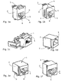
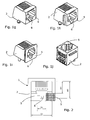
- FIG. 1a to 1j show various embodiments of sockets, as they comply with the international standard IEC 60603-7.
- These sockets 1 have a housing 2, the outer design and dimensions of which meets the respective requirements and fields of application and in particular is limited by the standard IEC 60603-7.
- the housing 2 according to FIG. 1a, 1b and 1f device-side contacts 3, which protrude in the insertion direction A from the housing.
- the housing 2 according to FIG. 1c, 1d and 1e on the other hand, device-side contacts 3, which protrude at right angles to the insertion direction A from the housing 2.
- these housings 2 are provided with a cavity 4 for receiving an RJ45 plug.
- This cavity has essentially a rectangular opening cross-section, at its one longer side an additional groove for receiving a locking tab of the RJ45 connector is provided.
- This groove forms a latching region 6 and causes steps 5 to be formed in the corner region immediately adjacent to the latching region 6 of the housing 2.
- FIG. 2 shows the dimensioning and dimensioning of the standardized cross section of an SFF socket 1 according to standard IEC 60603-7.
- the default values are shown in the following table: Table 2 description Maximum (mm) Minimum (mm) S 1 12.04 11.84 W 1 6.38 6.22 AC 1 6.96 6.76 AK 1 8.66 8.38
- housing areas 5 lying next to the latching area 6 have a cross section of at least approximately 3 ⁇ 3 mm 2 and are suitable for receiving additional feedthrough channels.
- FIG. 3 shows a hybrid socket 7 according to the invention with a housing 2 with a plug-side cavity 4 for receiving a normalized RJ45 plug.
- this socket 7 the conductors are led out of the housing 2 on the device side in the plugging direction A.
- the corner regions 8 lying directly next to the latching region 6 of the cavity 4 have step-shaped housing regions 5 in which through-ducts 9 are provided.
- the socket 7 can be added in a modular manner.
- Figure 3 shows a device side mounted on the housing 2 cable guide plate 17 to which, for example, means 22 are mounted for the strain relief.
- the housing 2 can be fastened, for example, to existing cans and patch systems.
- the feedthrough channels 9 are dimensioned such that they can interact, for example, with an optical plug 14.
- FIG. 4 shows the same socket 7 as in FIG. 3 with a housing 2 suitable for receiving an RJ45 plug.
- the plug-side front of this housing 2 is supplemented with a plug holder 11 which has plug guides 12 and plug latch openings 13.
- These plug guides 12 and plug latch openings 13 allow a guided insertion of an optical conductor and secure the contact between the plug 14 and the socket 7.
- the plug 14 has a plug closure sleeve 15 which is provided with latching lugs which cooperate with the Steckerrastö Anlagen Anlagen devisen13.
- the plug holder 11 shown also has locking elements 16 which can engage in openings of a mounting plate to correctly position and secure the plug holder 11 to this mounting plate.
- the plug guides 12 of this plug holder 11 are spaced apart and dimensioned such that the standards for optical plug systems according to IEEE 1394 be met. In particular, this arrangement allows the use of existing POF plugs and does not require specially shaped plugs.
- FIG. 5 shows the inventive connector housing 2 from its back.
- the design of the attached at the back of the housing 2 cable guide plate 17 is shown in detail.
- a duplex POF line 18, on the housing 2 9 grooves 19 are provided in the cable guide plate 17 in the direction of the feedthrough channels.
- the sensitive POF conductor 18 can be guided and protected in the intended manner.
- the ferrule, clamps 20 are preferably fastened, the geometry of which cooperates in a form-fitting manner with the geometry of the rear output of the feedthrough channels 9.
- FIG. 6 shows the inventive socket 7 in the assembled state.
- a plug holder 11 is arranged.
- the ferrules or optical fibers 21 can be easily inserted, position and secure. It is irrelevant whether the optical waveguide 21, respectively their ferrules, individual plug closure sleeves 15 or have a common and standardized according to IEEE 1394 plug termination.
- the bottom plate of the plug holder 11 has a recess R, such that the locking tab of the RJ45 plug is still accessible from the outside for unlocking.
- This plug holder 11 has latching elements 16 which can engage in mounting holes (not shown) of a front panel to correctly position and secure the plug holder 11.
- a module-holding plate 10 On the mounted on the housing 2 cable guide plate 17 is a module-holding plate 10, which on the one hand secures the mounted optical waveguide 18 and on the other hand allows to secure the housing 2 at a predetermined location in the device, in a patch panel or in a box. This arrangement also makes it possible to provide means 22 for the strain relief.
- FIG 7 shows the inventive socket 7 with respective passageways 9 for use with feed or coaxial cables 23.
- This socket 7 has substantially the same geometric structure, as the socket according to Figures 3 to 6.
- the plug holder 11 be adapted and / or these feed cables may be equipped with suitably sized connectors 24.
- the front panel 25 with the associated mounting holes 26 Smart Holes
- the front panel 25 additional extensions 27, between which the socket 7 can be fitted.
- FIG. 8 shows the same configuration as in FIG. 7, but in an exploded view.
- This illustration makes the modular structure of the inventive socket 7 clear.
- the device-side supply or coaxial connector 28 is connected to the back of the housing 2.
- This plug 28 is in turn composed of different elements in order to establish a correctly positioned connection and a good electrical contact can.
- the module holding plate 10 is applied, preferably snapped.
- the plug-in housing 2 connected in such a way to the feed or coaxial cable can now be fastened behind the front plate opening, preferably using the extensions 27.
- the plug holder 11 can be fastened to the front plate 25.
- the correctly guided and secured with the help of the plug holder 11 feed or coaxial cable 23 can be inserted correctly into the feedthrough channels 9 in this way.
- Figure 9 shows the configuration of the inventive plug-in housing 2 from its underside.
- the cable guide plate 17 in turn grooves 19 which are provided for receiving coaxial sockets 29.
- coaxial sockets are known and are connected to the coaxial cables 30 prior to assembly.
- the coaxial cables 31 to be connected are likewise connected to known coax plug connectors (PIN) 32.
- PIN coax plug connectors
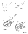
- Figure 10 shows a POF (plastic optical fiber) in which the sheath 34 is removed in the end region to be mounted. Over the exposed fiber 33, as shown in Figure 11, a ferrule 35 is pushed and fixed. The protruding from the ferrule 35 part of the exposed fiber is ground flush with the ferrule and polished before it, as shown in Figure 12, is inserted into a designated receptacle in an inventively designed SFF socket.
- Figures 13,14 make the swiveling of the ferrule 35 into the socket housing 2 and their exact positioning clear.
- the second fiber cable 36 is prepared and inserted analogously to the first fiber cable as shown in FIG.
- FIGS. 16 and 17 show a retaining clip 37, which ensures that the ferrules 35 are held securely in the housing 2.
- a retaining plate 10 shown in Figures 18 to 20 secures this retaining clip 37 and is used, moreover, the attachment of the example shown RJ45 hybrid socket in sockets or panels.
- an adapter frame 38 which serves the positioning and mounting of a normalized PN-POF connector 39 and can be easily plugged onto a front panel 25.
- the adapter frame 38 can with the help of a wedge-shaped ratchet pawl play with the socket 7 and thereby transformed the inventive RJ45 hybrid socket into a PN coupling, as shown in Figures 22, 23.
- the upper part of the adapter 38 is designed as a splitter according to US Pat. No. 6,419,527.
- Figures 24 and 25 show a lower housing part 40 of another embodiment of a combinable with a standardized RJ45 plug additional plug, which is designed so that it fits positively on a kink protection of an RJ45 connector, as described in US Pat. No. 6,520,796.
- This lower housing part 40 is designed for mounting an electrical contact pair, wherein the socket-side ends of this contact pair are provided with suitably dimensioned plug contact sleeves 41 and the cable-side ends of this contact pair have a crimp contact K for connection to a Litzencci.
- Figures 26 and 27 show an upper housing part 42, soft can be snapped with the lower housing part 40 and thus the two contacts K encloses.
- the lower housing part 40 has a latch 43 for locking an RJ45 plug and serves as contact protection.
- Figures 28 to 30 show how this additional plug can be attached to a bend protection 44 of an RJ45 connector and in particular by means of a film hinge 46 can be attached to this form-fitting manner.
- the inventive hybrid socket 7 is equipped with correspondingly dimensioned plug contact parts 47.
- the assembly takes place in an analogous manner, as in the POF ferrules 35 shown in Figures 34 and 35.
- Figures 36 and 37 show how the hybrid socket 7 according to the invention can be connected to an RJ45 plug on which a plug attachment 48 (as described with reference to Figures 24-30) is mounted.
- the embodiments described with the aid of the figures all have a housing 2 which is suitable for receiving an RJ45 plug, and are provided with feedthrough channels 9 in the housing areas 5 (area between the cavity for receiving the RJ45 plug and the outer dimensions of the SFF sockets), in particular immediately adjacent to the latching region 6 and the groove provided. It is understood that this universal interface constructed with such an SFF housing can be provided with additional supplementary modules in order to facilitate the assembly of the respective conductors or to guide, protect or fasten them in a controlled manner.
- the present invention thus allows the combination of connections of different types of cabling, without exceeding the specified by the standard IEC 60603-7 cross sections and makes it possible to use the connectors used for these different types of cabling - with the associated physical functions - simultaneously.
Landscapes
- Physics & Mathematics (AREA)
- General Physics & Mathematics (AREA)
- Optics & Photonics (AREA)
- Connector Housings Or Holding Contact Members (AREA)
- Non-Reversible Transmitting Devices (AREA)
- Mechanical Coupling Of Light Guides (AREA)
- Optical Couplings Of Light Guides (AREA)
- Coupling Device And Connection With Printed Circuit (AREA)
- Optical Communication System (AREA)
Description
- Die vorliegende Erfindung betrifft eine Hybrid-Steckbuchse gemäss Oberbegriff des Anspruchs 1, einen dazu passenden Hybrid-Stecker gemäss Oberbegriff des Anspruchs 6, einen Zusatzstecker gemäss Oberbegriff des Anspruchs 9 sowie einen Adapterrahmen gemäss Obergriff des Anspruchs. 10.
- Steckverbindungssysteme finden ihre Verwendung beispielsweise in der Computer-Technik, in der Telekommunikation und Bild- und Tonübertragung. Der vermehrte Einsatz dieser Techniken im Heim- und Bürobereich führt zu einer für den Nichtspezialisten unüberschaubaren Vielfalt von unterschiedlichen Stecksystemen. Es sind deshalb Tendenzen erkennbar, welche zur Zusammenlegung von mehreren, bisher unterschiedlich aufgebauten Verkabelungs- oder Stecksystemen führen. So wurde in letzter Zeit die Kommunikations- und Datenverkabelung in der sogenannten "universellen Gebäudeverkabelung" (UGV) zusammengeführt. Diese UGV entwickelt sich weiter, um weitere Anwendungsbereiche (z.B. Multimedia, Gebäudeautomation, Apparatesteuerungen) ausserhalb des Bürobereichs zu erschliessen (beispielsweise Heimbereich, Industriebereich): Unterstützt wird diese Entwicklung durch die Verbreitung des IP-Übertragungsprotokolls und die Entwicklung von Femspeisungsmöglichkeiten im Ethernet-Bereich gemäss IEEE 802.3. Eine weitere Entwicklung zeigt sich im Ausbau der Datenbandbreite, vor allem im Heimbereich, sowie Entwicklungen im Bereich der Kunststoff-Lichtwellenleiter mit einfach zu installierenden Verkabelungen.
- Deshalb sind bereits verschiedene Universalschnittstellen, respektive Hybrid-Steckverbindungssysteme bekannt, mit welchen unterschiedliche Kabelarten, beispielsweise Kupferkabel und Lichtwellenleiter, nebeneinander gekoppelt werden können. Ein derartiges Hybrid-Verbindungssystem ist beispielsweise in der EP 1 102 099 beschrieben. Dieses Hybrid-Verbindungssystem erlaubt es, optische Leiter und Kupferkabel gleichzeitig und unabhängig voneinander zu koppeln. Dazu wird ein Buchsengehäuse vorgeschlagen, in welchem sowohl Lichtleiterkabel als auch Kabel für die Übertragung elektrischer Signale nebeneinander geführt werden. Dieses Hybrid-Verbindungssystem ist verhältnismässig voluminös und erlaubt es nicht, konventionelle RJ45-Stecker gemäss Norm ISO/IEC 11801 zu verwenden.
- Eine Hybrid-Steckbuchse, welche es erlaubt, sowohl konventionelle RJ45-Stecker zu verwenden, als auch optische Kontakte herzustellen, ist in der WO 98/18033 beschrieben. Bei dieser Buchse sind optisch leitende Elemente vorgesehen, an welche, mit Hilfe eines geeignet dimensionierten Adapters, optische Leiter angekoppelt werden können. Mit dieser Hybrid-Steckbuchse kann entweder eine elektrische Verbindung oder eine optische Verbindung hergestellt werden, jedoch können nicht verschiedenartige Leitersysteme gleichzeitig verwendet werden. Diese Hybrid-Steckbuchse lässt also die gleichzeitige Verwendung von verschiedenen voneinander unabhängigen Steckern nicht zu.
- Dieser Mangel soll durch den Steckverbinder gemäss DE-U 201 13 501 behoben werden. Dieser Steckverbinder weist eine Steckbuchse auf, in welche ein RJ45-Stecker und gleichzeitig ein optisches Kabelpaar eingesteckt werden können. Dazu weist die Steckbuchse ein zusätzliches Gehäuse auf, an welchem Aufnahmeöffnungen für die Führung von Steuer- und Leistungskabel angebracht sind. Diese Hybrid-Steckbuchse weist gegenüber konventionellen RJ45-Steckbuchsen erweiterte Aussendimensionen auf und ist ungeeignet, um in bestehenden Patch-Panels oder Multimedia-Dosen eingesetzt werden zu können.
- Zusammenfassend, erfordern die bekannten Hybrid-Stecksystem alle entweder einen besonders ausgestalteten Hybrid-Stecker, d.h. dass für diese Systeme bestehende, konventionelle Stecker nicht verwendet werden können, oder stellen Einzellösungen für vorgegebene Kabelkombinationen dar, d.h. lassen die gleichzeitige Verwendung von voneinander unabhängigen Steckern nicht zu, oder erfordern eine Hybrid-Steckbuchse mit Aussendimensionen, welche die Abmasse der internationalen Norm (IEC 60603-7) überschreiten und deshalb nicht in bestehenden Patch-Panels oder Multimedia-Dosen verwendet werden können.
- Es ist deshalb die Aufgabe der vorliegenden Erfindung, eine Universalschnittstelle für ein Hybrid-Stecksystem zu schaffen, welche es erlaubt, mit Hilfe von genormten Steckern für verschiedene Anwendungen, insbesondere für RJ45-Stecker, die Verbindung von elektrischen Kabeln (z.B. Kupferkabel für die Telekommunikation, Signalkabel) mit einer Verbindung von anderen elektrischen Kabeln (z.B. abgeschirmten Steuer- oder Leistungskabeln) oder mit einer genormten Verbindung von optischen Leitern zu kombinieren.
- Insbesondere ist es Aufgabe der vorliegenden Erfindung, eine Hybrid-Steckbuchse zu schaffen, welche in bestehende Patch-Panels oder Multimedia-Dosen eingebaut werden kann, d.h. keinen Aussenquerschnitt aufweist, der die Abmasse der Norm IEC 60603-7 überschreitet.
- Erfindungsgemäss wird diese Aufgabe mit einer Universalschnittstelle gelöst, welche eine Hybrid-Steckbuchse mit den Merkmalen des Anspruchs 1 umfasst und insbesondere durch eine Hybrid-Steckbuchse für international normierte "Small Form Factor", respektive "SFF"-Stecksysteme, sowie RJ45-Stecker gemäss IEC 60603-7, bei welcher in den Stufen seitlich des Rastbereichs durchgehende Hohlräume, im folgenden auch Durchführungskanäle genannt oder geeignet angeordnete Aussparungen, aufweist. Unter SFF-Stecksystemen werden im folgenden die in der Norm IEC 60603-7 (1996-11) definierten Buchsen und dazu passenden Stecker verstanden.
Tabelle 1 - Small Form Factor (SFF) Buchsen Variante gem. Norm IEC 60603-7 (1996-11) Höhe in mm Breite in mm Typ A, Variante 01 a1 =18,0 -18,5 c1 =15,6 -16,1 Typ A, Variante 02 a1 =17,8 -18,3 c1 =13,8 -13,9 Typ A, Variante 03 a1 =19,3 max. p1 =14,4 -14,6 Typ B, Variante 01 a1 = 16,1 - 16,5 c1 =15,5 -15,6 Typ B, Variante 02 a1 = 15,8 -16,2 c1 = 15,5 -15,6 Typ B, Variante 03 a1 = 10,8 - 11,2 c1 =15,5 -15,6 Typ B, Variante 04 a1 =14,9 -15,1 c1 = 15,1 - 15,4 Typ B, Variante 05 a1 = 14,9 - 15,1 c1 =15,1-15,4 Typ B, Variante 06 a1 = 17,2 -17,4 c1 = 15,1 - 15,4 Typ B, Variante 07 a1 = 15,8 - 16,0 x1 = 15,4 - 15,6 - In einer ersten Ausführungsform weist die erfindungsgemässe Hybrid-Steckbuchse ein Gehäuse mit einer steckerseitigen Öffnung respektive Kavität für die Aufnahme eines normierten RJ45-Steckers auf. Die unmittelbar neben dem Rastbereich dieser steckerseitigen Kavität liegenden Stufen sind erfindungsgemäss mit Durchführungskanäle versehen. Diese Durchführungskanäle führen geräteseitig in Rillen einer Kabelführungsplatte, in welche beispielsweise Lichtwellenleiter eingelegt werden können. Bei dieser Ausführungsform kann auf die Kabelführungsplatte eine Halteplatte befestigt werden, welche einerseits die montierten Kabel sichert und schützt und welche andererseits dazu dienen kann, das gesamte Gehäuse im Gerät in einem Gerät, einer Dose oder einem Patchpanel zu befestigen. Steckerseitig kann die erfindungsgemässe Hybrid-Steckbuchse mit einem Steckerhalter ergänzt werden, welcher beispielsweise mit Hilfe von Rastelementen an der mit Rastöffnungen versehenen Montageplatte befestigt werden kann.
- In einer anderen Ausführungsform kann die Kabelführungsplatte für die Führung von Mini-Koax-Kabeln oder Speisekabeln besonders ausgestaltet sein. Es versteht sich, dass die Durchführungskanäle mit geeigneten Kupplungselementen oder Kabelführungselementen versehen sein können.
- Bevorzugte Weiterbildungen und Ausführungsformen der erfindungsgemässen Hybrid-Steckbuchse weisen die Merkmale der Unteransprüche 2 - 5 auf.
- Die erfindungsgemässen Durchführungskanäle erlauben also die unabhängige Aufnahme eines elektrischen und/oder optischen Bauteils, insbesondere von POFs (Plastic Optical Fibres) gemäss IEEE 1394, Mini-Coax-Kabeln, Stromversorgungs- oder Steuerkabeln, optischen Elementen (beispielsweise Leuchtdioden für das Monitoring) oder Bauteile für kabellose Übertragungssysteme. Insbesondere erlaubt die erfindungsgemässe Universal-Schnittstelle die Kombination von bekannten Verkabelungssystemen, wie sie im Multimedia-Bereich, im Industriebereich oder im (kabellosen) Bürobereich verwendet werden.
- Darüber hinaus erlaubt der Abstand der Durchführungskanäle die Verwendung von bestehenden Lichtwellenleiter-Stecksystemen gemäss Norm IEEE 1394.
- Im folgenden soll die Erfindung anhand verschiedener Ausführungsbeispiele mit Hilfe der Figuren näher erläutert werden. Es zeigen:
- Fig. 1a - 1j
- verschiedene Ausführungsformen international normierter SFF-Steckbuchsen für RJ45-Stecker;
- Fig. 2
- eine schematische Darstellung für die von der Norm festgelegten Abmasse dieser international normierten RJ45-Steckbuchsen;
- Fig. 3
- eine räumliche Darstellung einer erfindungsgemässen Universalschnittstelle mit einer Steckbuchse für mindestens einen zusätzlichen optischen Leiter;
- Fig. 4
- eine räumliche Darstellung einer erfindungsgemässen Schnittstelle mit einem Steckerhalter;
- Fig. 5
- eine bodenseitige Ansicht der erfindungsgemässen Steckbuchse;
- Fig. 6
- eine bodenseitige Ansicht der erfindungsgemässen Steckbuchse mit Steckerhalter und montierter Modul-Halteplatte;
- Fig. 7
- eine Ansicht der erfindungsgemässen Steckbuchse mit elektrischen Leitern;
- Fig. 8
- eine Explosionsdarstellung einer erfindungemässen Steckbuchse mit elektrischen Leitern;
- Fig. 9
- eine Explosionsdarstellung einer Unteransicht einer erfindungsgemässen Steckbuchse mit Mini-Koax-Kabel;
- Fig. 10 - 20
- die Montage von Lichtwellenleitern in eine erfindungsgemässe Steckbuchse;
- Fig. 21 - 23
- die Verwendung eines Adapterrahmens für die Positionierung eines normierten PM-POF-Steckers;
- Fig. 24 - 30
- den Aufbau und die Montage eines aufsetzbaren Zusatzsteckers;
- Fig. 31 -35
- die Montage von buchsenseitigen Kontakten für einen Zusatzstecker;
- Fig. 36, 37
- eine erfindungsgemässe Universal-Schnittstelle.
- Die Figuren 1a bis 1j zeigen verschiedene Ausführungsformen von Steckbuchsen, wie sie dem internationalen Standard IEC 60603-7 entsprechen. Diese Buchsen 1 weisen ein Gehäuse 2 auf, dessen äussere Gestaltung und Dimensionierung den jeweiligen Anforderungen und Einsatzgebieten entgegenkommt und insbesondere durch die Norm IEC 60603-7 begrenzt ist. So zeigen die Gehäuse 2 gemäss Fig. 1a, 1b und 1f geräteseitige Kontakte 3, welche in Steckrichtung A aus dem Gehäuse ragen. Die Gehäuse 2 gemäss Fig. 1c, 1d und 1e weisen demgegenüber geräteseitige Kontakte 3 auf, welche rechtwinklig zur Steckrichtung A aus dem Gehäuse 2 ragen. Steckerseitig sind diese Gehäuse 2 mit einer Kavität 4 für die Aufnahme eines RJ45-Steckers versehen. Diese Kavität hat im wesentlichen einen rechteckigen Öffnungsquerschnitt, an dessen einen längeren Seite eine zusätzliche Nut für die Aufnahme einer Rastlasche des RJ45-Steckers vorgesehen ist. Diese Nut bildet einen Rastbereich 6 und führt dazu, dass im Eckbereich unmittelbar neben dem Rastbereich 6 des Gehäuses 2 Stufen 5 entstehen.
- Figur 2 zeigt die Vermassung und Dimensionierung des genormten Querschnittes einer SFF-Steckbuchse 1 gemäss Norm IEC 60603-7. Die vorgegebenen Werte sind aus der folgenden Tabelle ersichtlich:
Tabelle 2 Bezeichnung Maximum (mm) Minimum (mm) S1 12,04 11,84 W1 6,38 6,22 AC1 6,96 6,76 AK1 8,66 8,38 - Diese Daten machen deutlich, dass die neben dem Rastbereich 6 liegenden Gehäusebereiche 5 einen Querschnitt von mindestens etwa 3 x3 mm2 aufweisen und geeignet sind, um zusätzliche Durchführungskanäle aufzunehmen.
- Figur 3 zeigt eine erfindungsgemässe Hybrid-Steckbuchse 7 mit einem Gehäuse 2 mit einer steckerseitigen Kavität 4 für die Aufnahme eines normierten RJ45-Steckers. Bei dieser Buchse 7 werden die Leiter geräteseitig in Steckrichtung A aus dem Gehäuse 2 herausgeführt. Die unmittelbar neben dem Rastbereich 6 der Kavität 4 liegenden Eckbereiche 8 weisen stufenförmige Gehäusebereiche 5 auf, in welchen Durchführungskanäle 9 vorgesehen sind. Es versteht sich, dass die Steckbuchse 7 in modularer Art und Weise ergänzt werden kann. So zeigt Figur 3 eine geräteseitig am Gehäuse 2 angebrachte Kabelführungsplatte 17, an welcher beispielsweise Mittel 22 für die Zugentlastung angebracht sind. Mit Hilfe einer Modul-Halteplatte 10 kann das Gehäuse 2 beispielsweise an bestehenden Dosen- und Patchsystemen befestigt werden. Die Durchführungskanäle 9 sind derart dimensioniert, dass diese beispielsweise mit einem optischen Stecker 14 zusammenwirken können.
- Figur 4 zeigt dieselbe Steckbuchse 7 wie in Figur 3 mit einem für die Aufnahme eines RJ45-Steckers geeigneten Gehäuse 2. Die steckerseitige Front dieses Gehäuses 2 ist mit einem Steckerhalter 11 ergänzt, welcher Steckerführungen 12 und Steckerrastöffnungen 13 aufweist. Diese Steckerführungen 12 und Steckerrastöffnungen 13 erlauben ein geführtes Einstecken eines optischen Leiters und sichern den Kontakt zwischen dem Stecker 14 und der Buchse 7. Vorteilhafterweise weist der Stecker 14 eine Steckerverschlusshülse 15 auf, welche mit Rastnasen versehen ist, die mit den Steckerrastöffnungen13 zusammenwirken. Der gezeigte Steckerhalter 11 weist darüber hinaus Rastelemente 16 auf, welche in Öffnungen einer Montageplatte eingreifen können, um den Steckerhalter 11 an dieser Montageplatte korrekt zu positionieren und zu befestigen. Die Steckerführungen 12 dieses Steckerhalters 11 sind derart voneinander beabstandet und dimensioniert, dass die Normen für optische Steckersysteme gemäss IEEE 1394 erfüllt werden. Insbesondere erlaubt diese Anordnung die Verwendung bestehender POF-Stecker und erfordert keine speziell geformeten Stecker.
- Die Ansicht in Figur 5 zeigt das erfindungsgemässe Steckergehäuse 2 von seiner Rückseite. Insbesondere ist die Gestaltung der an der Rückseite des Gehäuses 2 angebrachten Kabelführungsplatte 17 im Detail ersichtlich. Um die geräteseitigen Kabel, im vorliegenden Ausführungsbeispiel eine Duplex-POF-Leitung 18, am Gehäuse 2 zu befestigen, sind in Richtung der Durchführungskanäle 9 Rillen 19 in der Kabelführungsplatte 17 vorgesehen. In diesen Rillen 19 können die empfindlichen POF-Leiter 18 in vorgesehener Weise geführt und geschützt werden. An dem Kontaktende dieser Leiter, der Ferrule, werden vorzugsweise Klemmen 20 befestigt, deren Geometrie mit der Geometrie des rückseitigen Ausgangs der Durchführungskanäle 9 formschlüssig zusammenwirkt. Durch das Auflegen einer Modul-Halteplatte (nicht dargestellt) auf diese Kabelführungspaltte 17 wird die Duplex-POF-Leitung 18 zusätzlich gehalten und gesichert.
- Figur 6 zeigt die erfindungsgemässe Steckbuchse 7 im montierten Zustand. In dieser rückseitigen Ansicht ist steckerseitig des Gehäuses 2 ein Steckerhalter 11 angeordnet. Mit Hilfe dieses Steckerhalters 11 lassen sich die Ferrulen oder Lichtwellenleiter 21 in einfacher Weise einführen, positionieren und sichern. Dabei ist es unerheblich, ob die Lichtwellenleiter 21, respektive deren Ferrulen, individuelle Steckerverschlusshülsen 15 oder einen gemeinsamen und nach IEEE 1394 normierten Steckerabschluss aufweisen. Es versteht sich, dass die Bodenplatte des Steckerhalters 11 eine Aussparung R aufweist, derart, dass die Rastlasche des RJ45-Steckers weiterhin von aussen für die Entriegelung zugänglich ist. Dieser Steckerhalter 11 weist Rastelemente 16 auf, welche in Befestigungslöcher (nicht dargestellt) einer Frontplatte einrasten können, um den Steckerhalter 11 korrekt positionieren und befestigen zu können. Auf der am Gehäuse 2 angebrachte Kabelführungsplatte 17 liegt eine Modul-Halteplatte 10, welche einerseits die montierten Lichtwellenleiter 18 sichert und andererseits ermöglicht, das Gehäuse 2 an vorgegebener Stelle im Gerät, in einem Patchpanel oder in einer Dose zu befestigen. Diese Anordnung ermöglicht es ausserdem, Mittel 22 für die Zugentlastung vorzusehen.
- Figur 7 zeigt die erfindungsgemässe Steckbuchse 7 mit jeweiligen Durchgangskanälen 9 für die Verwendung mit Speise- oder Koaxialkabeln 23. Diese Steckbuchse 7 weist im wesentlichen denselben geometrischen Aufbau auf, wie die Steckbuchse gemäss Figuren 3 bis 6. Zur Führung der Speisekabel 23 kann der Steckerhalter 11 angepasst werden und/oder können diese Speisekabel mit geeignet dimensionierten Steckverbindern 24 ausgerüstet sein. Aus Figur 7 ist die Frontplatte 25 mit den dazugehörigen Befestigungslöchern 26 (Smart-Holes) ersichtlich. Um die Steckbuchse 7 und den Steckerhalter 11 gegenseitig ausrichten zu können, weist die Frontplatte 25 zusätzliche Fortsätze 27 auf, zwischen welche die Steckbuchse 7 eingepasst werden kann.
- Figur 8 zeigt dieselbe Konfiguration wie in Figur 7, jedoch in Explosionsdarstellung. Diese Darstellung macht den modulartigen Aufbau der erfindungsgemässen Buchse 7 deutlich. Bei der Montage wird an die Rückseite des Gehäuses 2 der geräteseitige Speise- oder Koaxstecker 28 angeschlossen. Dieser Stecker 28 setzt sich wiederum aus verschiedenen Elementen zusammen, um eine korrekt positionierte Verbindung und einen guten elektrischen Kontakt herstellen zu können. Zur Sicherung des Speise- oder Koaxsteckers 28 wird die Modul-Halteplatte 10 aufgebracht, vorzugsweise aufgeschnappt. Das derart mit dem Speise- oder Koaxkabel verbundene Steckgehäuse 2 kann nun hinter der Frontplattenöffnung befestigt werden, vorzugsweise unter Verwendung der Fortsätze 27. Mit Hilfe der Rastelemente 16 und der Befestigungslöcher 26 kann der Steckerhalter 11 an der Frontplatte 25 befestigt werden. Die mit Hilfe des Steckerhalters 11 korrekt geführten und gesicherten Speise- oder Koaxkabel 23 können auf diese Weise korrekt in die Durchführungskanäle 9 eingesteckt werden.
- Figur 9 zeigt die Ausgestaltung des erfindungsgemässen Steckgehäuses 2 von seiner Unterseite. Dabei weist die Kabelführungsplatte 17 wiederum Rillen 19 auf, die für die Aufnahme von Koaxial-Steckbuchsen 29 vorgesehen sind. Derartige Koaxial-Steckbuchsen sind bekannt und werden vor der Montage mit den Koax-Kabeln 30 verbunden. Steckerseitig werden die anzuschliessenden Koax-Kabel 31 ebenfalls mit bekannten Koax-Steckverbindem (PIN) 32 verbunden. Es versteht sich, dass bei dieser Ausführungsform im Innern der Durchführungskanäle 9 geeignete Kupplungsstücke mit Dielektrikum und Federkontakt eingesetzt werden, um eine elektrisch einwandfreie Verbindung gewährleisten zu können.
- Figur 10 zeigt eine POF (plastic optical fiber) Faser, bei welcher der Mantel 34 im zu montierenden Endbereich entfernt ist. Über die freigelegte Faser 33 wird, wie in Figur 11 gezeigt, eine Ferrule 35 aufgeschoben und fixiert. Der aus der Ferrule 35 herausragende Teil der freigelegten Faser wird zur Ferrule bündig abgeschliffen und poliert, bevor diese, wie in Figur 12 dargestellt, in eine dafür vorgesehene Aufnahme in einer erfindungsgemäss gestalteten SFF-Buchse eingefügt wird. Figuren 13,14 machen das Einschwenken der Ferrule 35 in das Buchsengehäuse 2 und deren exakte Positionierung deutlich. Das zweite Faserkabel 36 wird, wie in Figur 15 gezeigt, analog des ersten Faserkabels vorbereitet und eingefügt. Figuren 16 und 17 zeigen einen Halteclip 37, der dafür sorgt, dass die Ferrulen 35 sicher im Gehäuse 2 gehalten werden. Eine in den Figuren 18 bis 20 dargestellte Halteplatte 10 sichert diesen Halteclip 37 und dient, darüber hinaus der Befestigung der beispielsweise gezeigten RJ45-Hybridbuchse in Steckdosen oder Panels.
- In Figur 21 wird ein Adapterrahmen 38 dargestellt, welcher der Positionierung und Halterung eines normierten PN-POF-Steckers 39 dient und in einfacher Weise auf eine Frontplatte 25 aufgesteckt werden kann. Der Adapterrahmen 38 kann mit Hilfe einer keilförmig auflaufenden Klinke spielfrei mit der Buchse 7 verschnappen und transformiert dadurch die erfindungsgemässe RJ45-Hybridbuchse in eine PN-Kupplung, wie in den Figuren 22, 23 dargestellt. Zur weiteren Nutzung der RJ45-Kontakte ist der Oberteil des Adapters 38 als Splitter gemäss Patent US 6,419,527 ausgebildet.
- Figuren 24 und 25 zeigen ein Gehäuseunterteil 40 einer anderen Ausführungsform eines mit einem normierten RJ45-Steckers kombinierbaren Zusatzsteckers, welcher so ausgebildet ist, dass dieser formschlüssig auf einen Knickschutz eines RJ45-Steckers passt, wie in Patent US 6,520,796 beschrieben. Dieses Gehäuseunterteil 40 ist für die Montage eines elektrischen Kontaktpaares ausgebildet, wobei die buchsenseitigen Enden dieses Kontaktpaares mit geeignet dimensionierten Steckkontakthülsen 41 versehen sind und die kabelseitigen Enden dieses Kontaktpaares einen Crimp-Kontakt K für die Verbindung mit einem Litzenkabel aufweisen. Figuren 26 und 27 zeigen ein Gehäuseoberteil 42, weiches mit dem Gehäuseunterteil 40 verschnappt werden kann und damit die beiden Kontakte K umschliesst. Das Gehäuseunterteil 40 weist eine Klinke 43 für die Verriegelung eines RJ45-Steckers auf und dient als Berührungsschutz. Figuren 28 bis 30 zeigen, wie dieser Zusatzstecker an einem Knickschutz 44 eines RJ45-Steckers befestigt werden kann und insbesondere mit Hilfe eines Filmschamiers 46 an diesem formschlüssig angebracht werden kann.
- Für die Aufnahme dieser elektrischen Steckkontakthülsen 41 wird die erfindungsgemässe Hybrid-Buchse 7 mit entsprechend dimensionierten Steckkontaktteilen 47 ausgerüstet. Die Montage erfolgt in analoger Weise, wie bei den in Figuren 34 und 35 dargestellten POF-Ferrulen 35.
- Figuren 36 und 37 zeigen, wie die erfindungsgemässe Hybrid-Steckbuchse 7 mit einem RJ45-Stecker, auf den ein Steckeraufsatz 48 (wie anhand der Figuren 24 - 30 beschrieben) aufgesetzt ist, verbunden werden kann.
- Die mit Hilfe der Figuren beschriebenen Ausführungsformen weisen alle ein Gehäuse 2 auf, welches für die Aufnahme eines RJ45-Steckers geeignet ist, und sind mit Durchführungskanälen 9 in den Gehäusebereichen 5 (Bereich zwischen der Kavität für die Aufnahme des RJ45-Steckers und den Aussendimensionen der SFF-Buchsen), insbesondere unmittelbar neben dem Rastbereich 6 respektive der Nut versehen. Es versteht sich, dass diese mit einem derartigen SFF-Gehäuse aufgebaute Universalschnittstelle mit zusätzlichen Ergänzungsmodulen versehen sein kann, um die Montage der jeweiligen Leiter zu erleichtern respektive diese kontrolliert zu führen, zu schützen oder zu befestigen.
- Die vorliegende Erfindung erlaubt also die Kombination von Verbindungen unterschiedlicher Verkabelungsarten, ohne die durch die Norm IEC 60603-7 vorgegebenen Querschnitte zu überschreiten und ermöglicht es, die für diese unterschiedlichen Verkabelungsarten verwendeten Stecker - mit den jeweils zugeordneten physikalischen Funktionen - gleichzeitig einzusetzen.
Claims (9)
- Hybrid-Steckbuchse (7) mit einem Gehäuse (2) zum Einbau in ein Gerät, wobei das Gehäuse (2) eine Kavität (4) für die Aufnahme eines normierten RJ45-Steckers aufweist, welcher entlang der Steckrichtung A einsteckbar ist, dadurch gekennzeichnet, dass dieses Gehäuse (2) eine am Gehäuse (2) angebrachte Kabelführungsplatte (17) aufweist und für die Kombination von Verbindungen unterschiedlicher Verkabelungsart in einem neben der Kavität (4) liegenden stufenförmigen Gehäusebereich (5) neben dem Rastbereich (6) Mittel für die gleichzeitige Aufnahme eines elektrischen und/oder optischen Bauteils aufweist, welche Mittel Aussparungen und/oder Durchführungskanäle (9) für die Aufnahme von elektrischen und/oder optischen Steckern umfassen, derart, dass die elektrischen und/oder optischen Bauteile geräteseitig in Steckrichtung A aus dem Gehäuse (2) herausführbar sind.
- Hybrid-Steckbuchse (7) nach Anspruch 1, dadurch gekennzeichnet, dass das Gehäuse (2) ein Small-Form-Factor-Gehäuse ist.
- Hybrid-Steckbuchse (7) nach Anspruch 1 oder 2, dadurch gekennzeichnet, dass die Mittel für die Aufnahme eines elektrischen und/oder optischen Bauteils Aussparungen und/oder Durchführungskanäle (9) in dem unmittelbar neben einem Rastbereich (6) liegenden Gehäusebereich (5) sind.
- Hybrid-Steckbuchse (7) nach Anspruch 1 oder 2, dadurch gekennzeichnet, dass die Mittel für die Aufnahme eines elektrischen und/oder optischen Bauteils Aussparungen und/oder Durchführungskanäle (9) in einem, einem Rastbereich (6) gegenüberliegenden Gehäusebereich (5) sind.
- Hybrid-Steckbuchse (7) nach Anspruch 1oder 2, dadurch gekennzeichnet, dass die Mittel für die Aufnahme eines elektrischen und/oder optischen Bauteils Aussparungen und/oder Durchführungskanäle (9) in einem seitlich der Kavität (4) liegenden Gehäusebereich (5) sind.
- Hybrid-Stecker mit einem RJ45 Stecker und elektischen und/oder optischen Steckern für die Verwendung mit einer Hybrid-Steckbuchse (7) gemäss Anspruch 1.
- Hybrid-Stecker nach Anspruch 6, dadurch gekennzeichnet, dass dieser einen auf einen normierten RJ45-Stecker formschlüssig aufsetzbaren Zusatzstecker (48) umfasst.
- Hybrid-Stecker nach Anspruch 7, dadurch gekennzeichnet, dass der Zusatzstecker (48) eine Klinke (43) für die Verriegelung eines RJ45-Steckers aufweist.
- Zusatzstecker (48) zur Bildung eines Hybrid-Steckers aus dem Zusatzstecker und einem RJ45 Stecker für die Verwendung mit einer Hybrid-Steckbuchse (7) gemäss Anspruch 1.
Applications Claiming Priority (5)
| Application Number | Priority Date | Filing Date | Title |
|---|---|---|---|
| CH7482002 | 2002-05-02 | ||
| CH748022002 | 2002-05-02 | ||
| CH3952003 | 2003-03-12 | ||
| CH395032003 | 2003-03-12 | ||
| PCT/CH2003/000286 WO2003093888A1 (de) | 2002-05-02 | 2003-05-02 | Hybrid-steckverbindung |
Publications (2)
| Publication Number | Publication Date |
|---|---|
| EP1504297A1 EP1504297A1 (de) | 2005-02-09 |
| EP1504297B1 true EP1504297B1 (de) | 2007-02-14 |
Family
ID=29402948
Family Applications (1)
| Application Number | Title | Priority Date | Filing Date |
|---|---|---|---|
| EP03747381A Expired - Lifetime EP1504297B1 (de) | 2002-05-02 | 2003-05-02 | Hybrid-Steckverbindung |
Country Status (10)
| Country | Link |
|---|---|
| US (1) | US7147519B2 (de) |
| EP (1) | EP1504297B1 (de) |
| JP (1) | JP2005529354A (de) |
| KR (1) | KR100749590B1 (de) |
| AT (1) | ATE354110T1 (de) |
| AU (1) | AU2003226996A1 (de) |
| DE (1) | DE50306509D1 (de) |
| ES (1) | ES2280767T3 (de) |
| PL (1) | PL372843A1 (de) |
| WO (1) | WO2003093888A1 (de) |
Families Citing this family (37)
| Publication number | Priority date | Publication date | Assignee | Title |
|---|---|---|---|---|
| US20050162336A1 (en) * | 2004-01-27 | 2005-07-28 | Dell Products L.P. | System and apparatus for providing dual independent displays |
| WO2005114274A1 (en) | 2004-05-14 | 2005-12-01 | Molex Incorporated | Light pipe assembly for use with small form factor connector |
| KR100608910B1 (ko) * | 2004-08-16 | 2006-08-08 | 한국전자통신연구원 | 이더넷 통신용 광 45 커넥터 |
| ATE397230T1 (de) * | 2005-11-02 | 2008-06-15 | Tkm Telekommunikation Und Elek | Steckverbinder und steckkupplung in form eines rj45-anschlusssystems |
| US20080013909A1 (en) * | 2006-07-14 | 2008-01-17 | Tenvera, Inc. | Modular Optical Fiber Network Interface |
| US20080011514A1 (en) * | 2006-07-14 | 2008-01-17 | Tenvera, Inc. | Optical Fiber Distribution Apparatus and Method |
| US20080013907A1 (en) * | 2006-07-14 | 2008-01-17 | Tenvera, Inc. | Optical Fiber Blowing Device and Method |
| US20080013893A1 (en) * | 2006-07-14 | 2008-01-17 | Tenvera, Inc. | Optical Fiber Ferrule and Ferrule Receiver, and Method for Manufacturing the Same |
| US20080013957A1 (en) * | 2006-07-14 | 2008-01-17 | Tenvera, Inc. | Service Aggregation Gateway |
| US20080013956A1 (en) * | 2006-07-14 | 2008-01-17 | Tenvera, Inc. | Provisioning of Services Via an Optical Fiber Network |
| US20080011990A1 (en) * | 2006-07-14 | 2008-01-17 | Tenvera, Inc. | Installation of Fiber Optic Cables |
| US7490996B2 (en) | 2006-08-16 | 2009-02-17 | Sigmund Sommer | Electro-optical plug and receptacle |
| FR2923618B1 (fr) * | 2007-11-14 | 2010-06-04 | Nexans | Prise optique pour reseau de telecommunication |
| US8435047B2 (en) | 2007-12-04 | 2013-05-07 | Molex Incorporated | Modular connectors with easy-connect capability |
| DE102007062658A1 (de) | 2007-12-24 | 2009-06-25 | Bktel Communications Gmbh | Hybrid-Steckverbindung |
| US7798726B2 (en) * | 2008-08-22 | 2010-09-21 | Hon Hai Precision Ind. Co., Ltd. | Electrical connector with improved signal transmission means |
| KR101009407B1 (ko) * | 2008-11-13 | 2011-01-19 | 한국광기술원 | 광 전기 동시 접속 페룰 및 그를 이용한 커넥터 |
| TWM374177U (en) * | 2009-07-03 | 2010-02-11 | Tyco Holdings Holdings Bermuda No 7 Ltd | Electrical connector assembly |
| US8467654B2 (en) | 2010-04-05 | 2013-06-18 | Avago Technologies General Ip (Singapore) Pte. Ltd. | Modular connector assembly configured with both optical and electrical connections for providing both optical and electrical communications capabilities, and a system that incorporates the assembly |
| US8376630B2 (en) | 2010-04-05 | 2013-02-19 | Avago Technologies Fiber Ip (Singapore) Pte. Ltd. | Hybrid 8P8C RJ-45 modular plug configured with both optical and electrical connections for providing both optical and electrical communications capabilities, and a method |
| US8794850B2 (en) | 2010-04-05 | 2014-08-05 | Avago Technologies General Ip (Singapore) Pte. Ltd. | Adapter configured with both optical and electrical connections for providing both optical and electrical communications capabilities |
| US7993166B1 (en) * | 2010-06-01 | 2011-08-09 | Hon Hai Precision Ind. Co., Ltd. | Hybrid modular jack |
| US20120069516A1 (en) * | 2010-09-22 | 2012-03-22 | Panasonic Corporation | Electronic apparatus |
| CN102819070B (zh) * | 2011-06-07 | 2014-10-29 | 富士康(昆山)电脑接插件有限公司 | 线缆连接器 |
| TWM422823U (en) * | 2011-09-15 | 2012-02-11 | Delta Electronics Inc | Power distribution unit and power input module compatible therewith |
| TR201807736T4 (tr) * | 2012-05-14 | 2018-06-21 | Hcs Kablolama Sistemleri Sanayi Ve Ticaret Anonim Sirketi | Bir bilgisayar ağında kullanılmak üzere bir keystone jakı. |
| US8915653B2 (en) * | 2013-03-15 | 2014-12-23 | Tyco Electronics Corporation | Optical connector housing assembly with dual insertion and extraction options |
| CN104300329A (zh) * | 2013-11-29 | 2015-01-21 | 中航光电科技股份有限公司 | 带有rj45模块的混装连接器组件 |
| US10712504B2 (en) | 2016-04-01 | 2020-07-14 | Commscope Technologies Llc | Hybrid electrical and fiber optic outlet |
| EP3803485B1 (de) * | 2018-05-30 | 2026-04-29 | Corning Research & Development Corporation | Modulares glasfaserspleissablagesystem |
| KR102676844B1 (ko) * | 2018-11-06 | 2024-06-21 | 삼성전자주식회사 | 어댑터 및 이를 갖는 전자시스템 |
| CN114077020A (zh) * | 2020-08-18 | 2022-02-22 | 华为技术有限公司 | 复合模块及其制造方法 |
| CN112164939A (zh) * | 2020-10-10 | 2021-01-01 | 南京华脉科技股份有限公司 | 一种现场端接的智能型rj口插头连接器 |
| US11650379B2 (en) | 2020-10-14 | 2023-05-16 | Us Conec Ltd. | Anti-buckling latch for a fiber optic connector |
| DE102020134892A1 (de) | 2020-12-23 | 2022-06-23 | Reichle & De-Massari Ag | Steckbuchse, Steckverbindersystem, Steckbuchsenkit und Verfahren zur Herstellung einer Steckbuchse mit einem Steckbuchsenkit |
| CN114047582B (zh) * | 2021-11-23 | 2022-12-27 | 贵州电网有限责任公司 | 一种智能化变电站二次设备辅助维护连接器 |
| DE102023133923A1 (de) * | 2023-12-05 | 2025-06-05 | Harting Electric Stiftung & Co. Kg | Steckverbindermodul für einen modularen Industriesteckverbinder |
Citations (1)
| Publication number | Priority date | Publication date | Assignee | Title |
|---|---|---|---|---|
| DE20113501U1 (de) * | 2001-08-14 | 2001-10-11 | HARTING KGaA, 32339 Espelkamp | Steckverbinder mit Adapter |
Family Cites Families (10)
| Publication number | Priority date | Publication date | Assignee | Title |
|---|---|---|---|---|
| US4362905A (en) * | 1980-01-29 | 1982-12-07 | Nassar Ismail | Universal adapters for modular plug telephones |
| US4494815A (en) * | 1982-11-19 | 1985-01-22 | At&T Technologies, Inc. | Self-aligning cover for modular tricoupler |
| US4834661A (en) * | 1985-06-27 | 1989-05-30 | Universal Data Systems, Inc. | Busy-out line connector |
| US4714440A (en) * | 1985-10-28 | 1987-12-22 | American Telephone And Telegraph Company, At&T Technologies, Inc. | Universal adapter and methods of and apparatus for making same |
| US5741152A (en) * | 1995-04-25 | 1998-04-21 | Amphenol Corporation | Electrical connector with indicator lights |
| US5704802A (en) * | 1996-06-14 | 1998-01-06 | Maxconn Incorporated | Modular jack assembly |
| US6206724B1 (en) * | 1997-06-06 | 2001-03-27 | Tommy Y. Leung | Combined connector for ethernet and modem cables |
| DE19810561A1 (de) * | 1998-03-11 | 1999-09-16 | Siemens Ag | Hybrider Datenstecker |
| TW395574U (en) * | 1998-12-18 | 2000-06-21 | Hon Hai Prec Ind Co Ltd | Electrical connector assembly |
| US6682231B2 (en) * | 2000-12-14 | 2004-01-27 | Infineon Technologies North America Corp. | Optical subassembly and related methods for aligning an optical fiber with a light emitting device |
-
2003
- 2003-05-02 AU AU2003226996A patent/AU2003226996A1/en not_active Abandoned
- 2003-05-02 PL PL03372843A patent/PL372843A1/xx not_active Application Discontinuation
- 2003-05-02 WO PCT/CH2003/000286 patent/WO2003093888A1/de not_active Ceased
- 2003-05-02 KR KR1020047017628A patent/KR100749590B1/ko not_active Expired - Fee Related
- 2003-05-02 ES ES03747381T patent/ES2280767T3/es not_active Expired - Lifetime
- 2003-05-02 AT AT03747381T patent/ATE354110T1/de not_active IP Right Cessation
- 2003-05-02 JP JP2004502049A patent/JP2005529354A/ja active Pending
- 2003-05-02 EP EP03747381A patent/EP1504297B1/de not_active Expired - Lifetime
- 2003-05-02 DE DE50306509T patent/DE50306509D1/de not_active Expired - Fee Related
- 2003-05-02 US US10/512,949 patent/US7147519B2/en not_active Expired - Fee Related
Patent Citations (1)
| Publication number | Priority date | Publication date | Assignee | Title |
|---|---|---|---|---|
| DE20113501U1 (de) * | 2001-08-14 | 2001-10-11 | HARTING KGaA, 32339 Espelkamp | Steckverbinder mit Adapter |
Also Published As
| Publication number | Publication date |
|---|---|
| US7147519B2 (en) | 2006-12-12 |
| AU2003226996A1 (en) | 2003-11-17 |
| WO2003093888A1 (de) | 2003-11-13 |
| KR20040104689A (ko) | 2004-12-10 |
| KR100749590B1 (ko) | 2007-08-14 |
| JP2005529354A (ja) | 2005-09-29 |
| ES2280767T3 (es) | 2007-09-16 |
| ATE354110T1 (de) | 2007-03-15 |
| EP1504297A1 (de) | 2005-02-09 |
| US20050118880A1 (en) | 2005-06-02 |
| DE50306509D1 (de) | 2007-03-29 |
| PL372843A1 (pl) | 2005-08-08 |
Similar Documents
| Publication | Publication Date | Title |
|---|---|---|
| WO2003093888A1 (de) | Hybrid-steckverbindung | |
| DE102006000702B4 (de) | Anschlussvorrichtung | |
| DE102017008995B4 (de) | Verbinder | |
| DE60100091T2 (de) | Optischer und elektrischer Steckverbinder | |
| EP0762165B1 (de) | Hybrider Steckverbinder mit modularen elektrischen und Lichtwellenleiter-Steckverbindungen | |
| EP1566674B1 (de) | Steckergehäuse eines optischen Steckverbinders für die industrielle Umgebung | |
| EP1128494B1 (de) | Adapter und Stecker für die Kommunikations- und Steuerungstechnik | |
| DE10027901C2 (de) | Optisches Ringnetzwerk, optischer Steckverbinder und Hybrid-Steckverbinder | |
| DE69736583T2 (de) | Faseroptisches Steckersystem | |
| DE102011006586A1 (de) | Modulare Konnektorbaugruppe, welche sowohl mit optischen als auch mit elektrischen Verbindungen konfiguriert ist, zum Bereitstellen von sowohl optischen als auch elektrischen Kommunikationsfähigkeiten und System, welches die Baugruppe inkorporiert | |
| CH693657A5 (de) | Hybrider Datenstecker. | |
| DE29819314U1 (de) | Buchsenartiger Steckverbinder mit Filtereinrichtung | |
| DE102011079952A1 (de) | Adapter, welcher sowohl mit optischen als auch mit elektrischen Verbindungen zum Bereitstellen sowohl einer optischen als auch einer elektrischen Kommunikationsfähigkeit konfiguriert ist | |
| DE4118096C2 (de) | ||
| DE3751960T2 (de) | Schnittstelle für ein lokales Netz (LAN) | |
| EP1370446B8 (de) | Mobiltelefoneinrichtung mit mehradrigen elektrischen verbindungseinrichtungen | |
| EP2047571A1 (de) | Steckverbinder für die telekommunikations- und datentechnik | |
| EP1997194B1 (de) | Steckverbinder für die Telekommunikations- und Datentechnik | |
| EP0753906A2 (de) | Elektrische Steckvorrichtung | |
| EP1128198A1 (de) | Steckerteil für eine kombinierte optische und elektrische Steckverbindung | |
| EP0057255B1 (de) | Leitungsstecker für Flachbaugruppen | |
| EP2731205B1 (de) | Verbinder und Verwendung | |
| CH674281A5 (de) | ||
| DE102019112007A1 (de) | Steckverbinder | |
| DE102022101234A1 (de) | Anschlussdose |
Legal Events
| Date | Code | Title | Description |
|---|---|---|---|
| PUAI | Public reference made under article 153(3) epc to a published international application that has entered the european phase |
Free format text: ORIGINAL CODE: 0009012 |
|
| 17P | Request for examination filed |
Effective date: 20041202 |
|
| AK | Designated contracting states |
Kind code of ref document: A1 Designated state(s): AT BE BG CH CY CZ DE DK EE ES FI FR GB GR HU IE IT LI LU MC NL PT RO SE SI SK TR |
|
| AX | Request for extension of the european patent |
Extension state: AL LT LV MK |
|
| 17Q | First examination report despatched |
Effective date: 20050315 |
|
| DAX | Request for extension of the european patent (deleted) | ||
| GRAP | Despatch of communication of intention to grant a patent |
Free format text: ORIGINAL CODE: EPIDOSNIGR1 |
|
| RTI1 | Title (correction) |
Free format text: HYBRID PLUG CONNECTER |
|
| GRAS | Grant fee paid |
Free format text: ORIGINAL CODE: EPIDOSNIGR3 |
|
| GRAA | (expected) grant |
Free format text: ORIGINAL CODE: 0009210 |
|
| AK | Designated contracting states |
Kind code of ref document: B1 Designated state(s): AT BE BG CH CY CZ DE DK EE ES FI FR GB GR HU IE IT LI LU MC NL PT RO SE SI SK TR |
|
| PG25 | Lapsed in a contracting state [announced via postgrant information from national office to epo] |
Ref country code: NL Free format text: LAPSE BECAUSE OF FAILURE TO SUBMIT A TRANSLATION OF THE DESCRIPTION OR TO PAY THE FEE WITHIN THE PRESCRIBED TIME-LIMIT Effective date: 20070214 Ref country code: IE Free format text: LAPSE BECAUSE OF FAILURE TO SUBMIT A TRANSLATION OF THE DESCRIPTION OR TO PAY THE FEE WITHIN THE PRESCRIBED TIME-LIMIT Effective date: 20070214 Ref country code: SI Free format text: LAPSE BECAUSE OF FAILURE TO SUBMIT A TRANSLATION OF THE DESCRIPTION OR TO PAY THE FEE WITHIN THE PRESCRIBED TIME-LIMIT Effective date: 20070214 Ref country code: DK Free format text: LAPSE BECAUSE OF FAILURE TO SUBMIT A TRANSLATION OF THE DESCRIPTION OR TO PAY THE FEE WITHIN THE PRESCRIBED TIME-LIMIT Effective date: 20070214 Ref country code: FI Free format text: LAPSE BECAUSE OF FAILURE TO SUBMIT A TRANSLATION OF THE DESCRIPTION OR TO PAY THE FEE WITHIN THE PRESCRIBED TIME-LIMIT Effective date: 20070214 |
|
| REG | Reference to a national code |
Ref country code: GB Ref legal event code: FG4D Free format text: NOT ENGLISH |
|
| REG | Reference to a national code |
Ref country code: CH Ref legal event code: NV Representative=s name: HANS ULRICH SEIFERT SEIFERT & PARTNER Ref country code: CH Ref legal event code: EP |
|
| REF | Corresponds to: |
Ref document number: 50306509 Country of ref document: DE Date of ref document: 20070329 Kind code of ref document: P |
|
| REG | Reference to a national code |
Ref country code: IE Ref legal event code: FG4D Free format text: LANGUAGE OF EP DOCUMENT: GERMAN |
|
| GBT | Gb: translation of ep patent filed (gb section 77(6)(a)/1977) |
Effective date: 20070320 |
|
| PG25 | Lapsed in a contracting state [announced via postgrant information from national office to epo] |
Ref country code: SE Free format text: LAPSE BECAUSE OF FAILURE TO SUBMIT A TRANSLATION OF THE DESCRIPTION OR TO PAY THE FEE WITHIN THE PRESCRIBED TIME-LIMIT Effective date: 20070514 |
|
| PG25 | Lapsed in a contracting state [announced via postgrant information from national office to epo] |
Ref country code: BG Free format text: LAPSE BECAUSE OF EXPIRATION OF PROTECTION Effective date: 20070515 |
|
| PG25 | Lapsed in a contracting state [announced via postgrant information from national office to epo] |
Ref country code: PT Free format text: LAPSE BECAUSE OF FAILURE TO SUBMIT A TRANSLATION OF THE DESCRIPTION OR TO PAY THE FEE WITHIN THE PRESCRIBED TIME-LIMIT Effective date: 20070716 |
|
| NLV1 | Nl: lapsed or annulled due to failure to fulfill the requirements of art. 29p and 29m of the patents act | ||
| ET | Fr: translation filed | ||
| REG | Reference to a national code |
Ref country code: ES Ref legal event code: FG2A Ref document number: 2280767 Country of ref document: ES Kind code of ref document: T3 |
|
| REG | Reference to a national code |
Ref country code: IE Ref legal event code: FD4D |
|
| PG25 | Lapsed in a contracting state [announced via postgrant information from national office to epo] |
Ref country code: SK Free format text: LAPSE BECAUSE OF FAILURE TO SUBMIT A TRANSLATION OF THE DESCRIPTION OR TO PAY THE FEE WITHIN THE PRESCRIBED TIME-LIMIT Effective date: 20070214 |
|
| PLBE | No opposition filed within time limit |
Free format text: ORIGINAL CODE: 0009261 |
|
| STAA | Information on the status of an ep patent application or granted ep patent |
Free format text: STATUS: NO OPPOSITION FILED WITHIN TIME LIMIT |
|
| BERE | Be: lapsed |
Owner name: REICHLE & DE-MASSARI A.G. Effective date: 20070531 |
|
| PG25 | Lapsed in a contracting state [announced via postgrant information from national office to epo] |
Ref country code: RO Free format text: LAPSE BECAUSE OF FAILURE TO SUBMIT A TRANSLATION OF THE DESCRIPTION OR TO PAY THE FEE WITHIN THE PRESCRIBED TIME-LIMIT Effective date: 20070214 Ref country code: CZ Free format text: LAPSE BECAUSE OF FAILURE TO SUBMIT A TRANSLATION OF THE DESCRIPTION OR TO PAY THE FEE WITHIN THE PRESCRIBED TIME-LIMIT Effective date: 20070214 |
|
| 26N | No opposition filed |
Effective date: 20071115 |
|
| PG25 | Lapsed in a contracting state [announced via postgrant information from national office to epo] |
Ref country code: MC Free format text: LAPSE BECAUSE OF NON-PAYMENT OF DUE FEES Effective date: 20070531 |
|
| PG25 | Lapsed in a contracting state [announced via postgrant information from national office to epo] |
Ref country code: BE Free format text: LAPSE BECAUSE OF NON-PAYMENT OF DUE FEES Effective date: 20070531 |
|
| PG25 | Lapsed in a contracting state [announced via postgrant information from national office to epo] |
Ref country code: GR Free format text: LAPSE BECAUSE OF FAILURE TO SUBMIT A TRANSLATION OF THE DESCRIPTION OR TO PAY THE FEE WITHIN THE PRESCRIBED TIME-LIMIT Effective date: 20070515 |
|
| PG25 | Lapsed in a contracting state [announced via postgrant information from national office to epo] |
Ref country code: EE Free format text: LAPSE BECAUSE OF FAILURE TO SUBMIT A TRANSLATION OF THE DESCRIPTION OR TO PAY THE FEE WITHIN THE PRESCRIBED TIME-LIMIT Effective date: 20070214 |
|
| PG25 | Lapsed in a contracting state [announced via postgrant information from national office to epo] |
Ref country code: CY Free format text: LAPSE BECAUSE OF FAILURE TO SUBMIT A TRANSLATION OF THE DESCRIPTION OR TO PAY THE FEE WITHIN THE PRESCRIBED TIME-LIMIT Effective date: 20070214 |
|
| PGFP | Annual fee paid to national office [announced via postgrant information from national office to epo] |
Ref country code: ES Payment date: 20090521 Year of fee payment: 7 |
|
| PG25 | Lapsed in a contracting state [announced via postgrant information from national office to epo] |
Ref country code: LU Free format text: LAPSE BECAUSE OF NON-PAYMENT OF DUE FEES Effective date: 20070502 |
|
| PGFP | Annual fee paid to national office [announced via postgrant information from national office to epo] |
Ref country code: AT Payment date: 20090515 Year of fee payment: 7 Ref country code: DE Payment date: 20090525 Year of fee payment: 7 Ref country code: FR Payment date: 20090513 Year of fee payment: 7 Ref country code: IT Payment date: 20090523 Year of fee payment: 7 |
|
| PG25 | Lapsed in a contracting state [announced via postgrant information from national office to epo] |
Ref country code: HU Free format text: LAPSE BECAUSE OF FAILURE TO SUBMIT A TRANSLATION OF THE DESCRIPTION OR TO PAY THE FEE WITHIN THE PRESCRIBED TIME-LIMIT Effective date: 20070815 Ref country code: TR Free format text: LAPSE BECAUSE OF FAILURE TO SUBMIT A TRANSLATION OF THE DESCRIPTION OR TO PAY THE FEE WITHIN THE PRESCRIBED TIME-LIMIT Effective date: 20070214 |
|
| PGFP | Annual fee paid to national office [announced via postgrant information from national office to epo] |
Ref country code: CH Payment date: 20090514 Year of fee payment: 7 |
|
| PGFP | Annual fee paid to national office [announced via postgrant information from national office to epo] |
Ref country code: GB Payment date: 20090522 Year of fee payment: 7 |
|
| REG | Reference to a national code |
Ref country code: CH Ref legal event code: PL |
|
| GBPC | Gb: european patent ceased through non-payment of renewal fee |
Effective date: 20100502 |
|
| PG25 | Lapsed in a contracting state [announced via postgrant information from national office to epo] |
Ref country code: AT Free format text: LAPSE BECAUSE OF NON-PAYMENT OF DUE FEES Effective date: 20100502 |
|
| REG | Reference to a national code |
Ref country code: FR Ref legal event code: ST Effective date: 20110131 |
|
| PG25 | Lapsed in a contracting state [announced via postgrant information from national office to epo] |
Ref country code: CH Free format text: LAPSE BECAUSE OF NON-PAYMENT OF DUE FEES Effective date: 20100531 Ref country code: LI Free format text: LAPSE BECAUSE OF NON-PAYMENT OF DUE FEES Effective date: 20100531 |
|
| PG25 | Lapsed in a contracting state [announced via postgrant information from national office to epo] |
Ref country code: IT Free format text: LAPSE BECAUSE OF NON-PAYMENT OF DUE FEES Effective date: 20100502 |
|
| PG25 | Lapsed in a contracting state [announced via postgrant information from national office to epo] |
Ref country code: DE Free format text: LAPSE BECAUSE OF NON-PAYMENT OF DUE FEES Effective date: 20101201 |
|
| PG25 | Lapsed in a contracting state [announced via postgrant information from national office to epo] |
Ref country code: FR Free format text: LAPSE BECAUSE OF NON-PAYMENT OF DUE FEES Effective date: 20100531 |
|
| REG | Reference to a national code |
Ref country code: ES Ref legal event code: FD2A Effective date: 20110711 |
|
| PG25 | Lapsed in a contracting state [announced via postgrant information from national office to epo] |
Ref country code: ES Free format text: LAPSE BECAUSE OF NON-PAYMENT OF DUE FEES Effective date: 20110629 Ref country code: GB Free format text: LAPSE BECAUSE OF NON-PAYMENT OF DUE FEES Effective date: 20100502 |
|
| PG25 | Lapsed in a contracting state [announced via postgrant information from national office to epo] |
Ref country code: ES Free format text: LAPSE BECAUSE OF NON-PAYMENT OF DUE FEES Effective date: 20100503 |