EP1566674B1 - Steckergehäuse eines optischen Steckverbinders für die industrielle Umgebung - Google Patents
Steckergehäuse eines optischen Steckverbinders für die industrielle Umgebung Download PDFInfo
- Publication number
- EP1566674B1 EP1566674B1 EP04003701A EP04003701A EP1566674B1 EP 1566674 B1 EP1566674 B1 EP 1566674B1 EP 04003701 A EP04003701 A EP 04003701A EP 04003701 A EP04003701 A EP 04003701A EP 1566674 B1 EP1566674 B1 EP 1566674B1
- Authority
- EP
- European Patent Office
- Prior art keywords
- plug
- connector
- fastening means
- housing
- capsule
- Prior art date
- Legal status (The legal status is an assumption and is not a legal conclusion. Google has not performed a legal analysis and makes no representation as to the accuracy of the status listed.)
- Expired - Lifetime
Links
- 230000003287 optical effect Effects 0.000 title claims abstract description 26
- 239000002775 capsule Substances 0.000 claims abstract description 46
- 238000003780 insertion Methods 0.000 claims description 5
- 230000037431 insertion Effects 0.000 claims description 5
- 230000007774 longterm Effects 0.000 description 6
- 230000000295 complement effect Effects 0.000 description 5
- 230000000712 assembly Effects 0.000 description 4
- 238000000429 assembly Methods 0.000 description 4
- 238000011161 development Methods 0.000 description 3
- 230000018109 developmental process Effects 0.000 description 3
- 230000015572 biosynthetic process Effects 0.000 description 2
- 238000011109 contamination Methods 0.000 description 2
- 230000006378 damage Effects 0.000 description 2
- 238000013461 design Methods 0.000 description 2
- 239000000428 dust Substances 0.000 description 2
- 230000000694 effects Effects 0.000 description 2
- 230000007613 environmental effect Effects 0.000 description 2
- 239000000835 fiber Substances 0.000 description 2
- 238000000034 method Methods 0.000 description 2
- 238000007789 sealing Methods 0.000 description 2
- 230000005540 biological transmission Effects 0.000 description 1
- 238000004891 communication Methods 0.000 description 1
- 239000000356 contaminant Substances 0.000 description 1
- 239000013307 optical fiber Substances 0.000 description 1
- 230000001681 protective effect Effects 0.000 description 1
- 230000008054 signal transmission Effects 0.000 description 1
Images


Classifications
-
- G—PHYSICS
- G02—OPTICS
- G02B—OPTICAL ELEMENTS, SYSTEMS OR APPARATUS
- G02B6/00—Light guides; Structural details of arrangements comprising light guides and other optical elements, e.g. couplings
- G02B6/24—Coupling light guides
- G02B6/36—Mechanical coupling means
- G02B6/38—Mechanical coupling means having fibre to fibre mating means
- G02B6/3807—Dismountable connectors, i.e. comprising plugs
- G02B6/3873—Connectors using guide surfaces for aligning ferrule ends, e.g. tubes, sleeves, V-grooves, rods, pins, balls
- G02B6/3874—Connectors using guide surfaces for aligning ferrule ends, e.g. tubes, sleeves, V-grooves, rods, pins, balls using tubes, sleeves to align ferrules
- G02B6/3878—Connectors using guide surfaces for aligning ferrule ends, e.g. tubes, sleeves, V-grooves, rods, pins, balls using tubes, sleeves to align ferrules comprising a plurality of ferrules, branching and break-out means
- G02B6/3879—Linking of individual connector plugs to an overconnector, e.g. using clamps, clips, common housings comprising several individual connector plugs
-
- G—PHYSICS
- G02—OPTICS
- G02B—OPTICAL ELEMENTS, SYSTEMS OR APPARATUS
- G02B6/00—Light guides; Structural details of arrangements comprising light guides and other optical elements, e.g. couplings
- G02B6/24—Coupling light guides
- G02B6/36—Mechanical coupling means
- G02B6/38—Mechanical coupling means having fibre to fibre mating means
- G02B6/3807—Dismountable connectors, i.e. comprising plugs
- G02B6/389—Dismountable connectors, i.e. comprising plugs characterised by the method of fastening connecting plugs and sockets, e.g. screw- or nut-lock, snap-in, bayonet type
- G02B6/3893—Push-pull type, e.g. snap-in, push-on
-
- G—PHYSICS
- G02—OPTICS
- G02B—OPTICAL ELEMENTS, SYSTEMS OR APPARATUS
- G02B6/00—Light guides; Structural details of arrangements comprising light guides and other optical elements, e.g. couplings
- G02B6/24—Coupling light guides
- G02B6/36—Mechanical coupling means
- G02B6/38—Mechanical coupling means having fibre to fibre mating means
- G02B6/3807—Dismountable connectors, i.e. comprising plugs
- G02B6/3833—Details of mounting fibres in ferrules; Assembly methods; Manufacture
- G02B6/3847—Details of mounting fibres in ferrules; Assembly methods; Manufacture with means preventing fibre end damage, e.g. recessed fibre surfaces
- G02B6/3849—Details of mounting fibres in ferrules; Assembly methods; Manufacture with means preventing fibre end damage, e.g. recessed fibre surfaces using mechanical protective elements, e.g. caps, hoods, sealing membranes
Definitions
- the present invention relates to a connector housing for an optical SC-RJ connector, for receiving at least one Ferrulengepuruses, according to the preamble of claim 1.
- Plug housing for insertion into a corresponding socket generally serve the purpose of supporting and directing electrical or optical cables, in particular in order to be able to accomplish an electrical or optical connection of cable ends in a simple manner.
- Such connections for modern data and communication transmission are used outdoors as well as in the home, office or business and in the industry.
- so-called RJ45 connectors for electrical signal transmission have become established on the market.
- SC-RJ connectors respectively SC-RJ connector arrangements (plug / adapter / plug) for optical cables, detailed standards are already in place (EN 50377-6-1).
- a housing body for receiving an RJ45 connector which is suitable for use with plug contacts, as required under industrial environmental conditions.
- the disclosed in this document housing body is provided with a removable hinged lid and designed such that a standardized RJ45 plug can be inserted into this housing body.
- This housing body also has a laterally arranged pair of pawls, with the aid of which the mounted plug can be secured to a socket.
- the multi-part structure of this housing body protects the internal electrical contact points long term insufficient and can no longer meet the high demands for fiber optic contacts in an industrial environment.
- an electrical connector is described, which is designed for use in an industrial environment particularly.
- This arrangement also comprises a multi-part housing body with a pair of pawls arranged on both sides.
- no special measures are provided to protect the contact area in the long term from moisture, dust or other contaminants.
- vibrations are transmitted undamped to the contact points.
- this connector assembly should be dismountable without destruction.
- a plug housing with the features of claim 1, and in particular by a plug housing of an optical connector known type, which is suitable for receiving at least one Ferrulengephases, said connector housing has first fastening means for long-term secure attachment with a connector capsule to create an industrial grade connector.
- the connector housing according to the invention advantageously has first fastening means, which are suitable for releasable fastening with a connector capsule.
- first fastening means comprise at least one latching element for the formation of a snap closure which interacts with the connector capsule in a completely complementary manner.
- the first fastening means (16) comprise at least one latching element for the formation of a cooperating with the connector capsule complementary rotary snap closure.
- the latching element can have a simple latching groove or, in another embodiment, a latching latch.
- the latching element has a latching nose which is formed in a circular segment transverse to the plugging direction (R) in order to be guided without play in a guide groove in the interior of the plug connector capsule.
- a connector capsule which can accommodate the connector housing described above and cooperates with this in a suitable manner.
- second fastening means are provided for a detachable fastening with the connector housing according to the invention, which second fastening means cooperate in a manner complementary to the first fastening means of the plug housing.
- third fastening means are provided with which the connector capsule can be releasably secured to a mounting frame or a device housing.
- These third attachment means can as pawl, resp. Pawl pair be formed and engage behind the attachment frame or on the device housing effect complementary counter elements. Just as easily can also provide a union nut for the design of this third fastening means.
- this plug arrangement can be assembled with the aid of the plug housing formed according to the invention in a simple manner and preferably also dismantled without destruction.
- FIG. 1 shows a connector assembly 1 for two optical cables 2, 3, also called optical waveguide whose ends are each provided with a ferrule 4, 5.
- These ferrules 4, 5 are held in standard Ferrulengephaseusen 6 a, 6 b in a known manner, ie with the aid of Ferrulenhaltern 26 and Crimphülsen 27.
- the two optical cables 2, 3 are guided through a connector capsule 7 and protected by a cable sheath 8.
- This connector assembly 1 also has a bend protection 9 of known type, to protect the optical cable 2, 3 from unwanted kinking.
- a plug housing 10 is provided which accommodates the ferrule housings 6a, 6b and thus forms a plug connector 11, in particular a SC-RJ plug connector.
- the thus assembled plug assembly 15 can be inserted into an adapter 12 which is fixed by means of a support plate 13 to a mounting frame 14. It is understood that for such connector assemblies, a protective cap 25 is provided which can be plugged over the connector assembly 15 to protect the ends of the optical cables 2, 3.
- the connector housing 10 has first fastening means 16, which allow a snap connection with the connector capsule 7.
- these first fastening means 16 are formed as part of a rotary locking closure.
- a rotary-latch closure prevents the Extracting the plug assembly 15 from the socket assembly 30, the plug housing 10 is released from the connector capsule 7 and thus tensile forces on the optical cable 2, 3 are exercised.
- the plug housing 10 rests with its rear side on the opening edge 17 of the connector capsule 7.
- the connector capsule 7 is provided with an O-ring 21.
- the inventive connector shell 7 has a laterally arranged pair of latches 22, 22 'in order to secure the connector shell 7 to the mounting frame 14.
- FIGS. 2a to 2c show some assembly steps for assembling a connector assembly 15 according to the invention.
- a sealing element preferably a cable sheath 8 and a kink protection 9
- the cables 2, 3 stripped in a known manner about 7 cm and made up the individual fibers, ie in particular provided with a ferrule 4, 5 and possibly glued and ground.
- a connector capsule 7 is pushed over the cables 2, 3 prepared in this way.
- Each of the ferrules 4, 5 is previously secured in one of the ferrule housings 6a, 6b.
- These ferrule housings 6a, 6b are then inserted into the connector housing 10 according to the invention.
- this connector housing 10 is inserted into the connector capsule 7, as shown in FIGS FIGS. 2a to 2c it can be seen, and the anti-buckling 9 is sealingly attached to the connector capsule 7 and the cable sheath 8.
- the process by which the connector housing 10 is fixed to the connector capsule 7, is in the FIGS. 2a to 2c made clear.
- the first fastening means 16 of the plug housing 10 are inserted into the plug connector capsule 7 in a position rotated about the plugging direction R.
- FIG. 2b shows the plug housing 10 inserted into the connector capsule 7 as far as it will go.
- the rear wall of this connector housing 10 rests against the opening edge 17 of the connector capsule 7 in this position.
- a portion of the first fastening means 16, in particular a detent element 24 is now in a second fastening means, in particular in an inner detent groove (not shown) of the connector capsule 7.
- the plug housing 10 is brought with a rotation ⁇ around the plugging direction R and by means of second fastening means in a releasable rotational snap connection with the connector capsule 7.
- these second fastening means additionally comprise a latching notch provided on the latching groove into which a latching rib 29 of the latching groove Locking element 24 engages.
- the arrangement according to Figure 2c can now be used as a connector assembly 15 mounted according to the invention.
- FIGS. 3a to 3c show the inventive connector housing 10 and the inventive first fastening means 16 in detail.
- This plug housing 10 has two slots 18, 19 into which the ferrule housings 6a, 6b can be inserted.
- Lateral cams 20, as well as a coding cam (not shown) on the underside of the plug housing 10, ensure the correct insertion of the plug housing 10 into a bushing arrangement 30.
- the in Fig. 3b shown in detail first fastening means 16 comprise a web 23 which from the rear end of the plug housing 10 in the opposite direction, ie in the direction of the connector capsule 7 shows. This web 23 is dimensioned such that the ferrule housing 6a, 6b in the slots 18, 19 of the connector housing 10, also called slide housing, can be performed.
- the first attachment means 16 can engage in complementary second attachment means (not shown) within the connector capsule 7.
- FIGS. 3a to 3c illustrate the geometry of preferred first fastener 16 according to the invention.
- the web 23 comprises at least one head part 24 or 24 ', which is formed in a circular segment shape transversely to the direction of insertion R.
- the first fastening means 16 have a web 23 with two such head parts 24, 24 '.
- In the assembled state is at least one head part 24 in a provided in the interior of the connector capsule 7 circumferential groove (not shown). This groove has at a suitable location a threshold into which the head part 24 can releasably engage. In this way it is ensured that the plug housing 10 is no longer retractable in the opposite direction from the plug connector capsule 7, but can only be released from its detent position by means of a rotary movement - ⁇ .
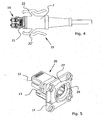
- FIG. 4 shows the assembled connector and makes it clear that the inventive connector housing 10 rests with its back on the opening edge of the connector capsule 7 and completely into a socket assembly 30 according to FIG. 5 can be introduced.
- FIGS. 4 and 5 illustrated plug assembly 15 and socket assembly 30 makes it clear that the contact point for the optical connection is fully protected by the inventive connector assembly 1, in particular so completely abkapselbar using the one-piece connector capsule 7 and thus works flawlessly and safely even in the face of difficult industrial environmental conditions.
- the O-ring 21 sealingly engages a stop surface 26 of an opening collar 27 of the mounting frame 14.
- This opening collar 27 is undercut, such that third fastening means, in particular at least one of the pawls 22, 22 'can engage behind this opening collar 27 and thus the plug assembly 15 can securely hold the socket assembly 30.
- the embodiments shown here is applicable to all types of optical connectors, but especially for SC-RJ connectors. It is irrelevant whether so only one or more optical cables are to be connected at the same time.
- the plug housing 10 according to the invention can be completely or only partially in the interior of the connector capsule 7 in the mounted state.
- the plug housing 10 or the individual FerrulengePSuse 6a, 6b may be provided with automatic closing flaps to protect the optical fibers in the unplugged state from contamination.
- the plug capsule 7 can be fixed instead of using pawls 22 by means of a union nut on the mounting frame 14 or on a device housing.
- Other means for secure attachment of the inventive connector assembly 15 are in the ordinary practice of the skilled person. So it goes without saying that the present invention equipped connector assembly 15 may also have automatic closing flaps or a manually attachable cap 25.
Landscapes
- Physics & Mathematics (AREA)
- General Physics & Mathematics (AREA)
- Optics & Photonics (AREA)
- Mechanical Coupling Of Light Guides (AREA)
- Optical Couplings Of Light Guides (AREA)
- Stored Programmes (AREA)
Description
- Die vorliegende Erfindung betrifft ein Steckergehäuse für einen optischen SC-RJ Stecker, für die Aufnahme mindestens eines Ferrulengehäuses, gemäss Oberbegriff des Anspruchs 1.
- Steckergehäuse zum Einstecken in eine korrespondierende Steckerbuchse dienen ganz allgemein der Halterung und gezielten Führung von elektrischen oder optischen Kabeln, insbesondere um eine elektrische oder optische Verbindung von Kabelenden in einfacher Weise bewerkstelligen zu können. Derartige Verbindungen für die moderne Daten- und Kommunikationsübertragung werden im Aussenbereich ebenso verwendet, wie im Wohnbereich, Büro- oder Geschäftsbereich und in der Industrie. So haben sich zum Beispiel sogenannte RJ45-Stecker für die elektrische Signalübertragung auf dem Markt durchgesetzt. Für die Geometrie von sogenannten SC-RJ Steckern, respektive SC-RJ Steckverbinderanordnungen (Stecker/Adapter/Stecker) für optische Kabel bestehen bereits detaillierte Normvorschriften (EN 50377-6-1).
- Bei der Verwendung derartiger Steckverbinderanordnungen in industrieller Umgebung erweisen sich diese jedoch als äusserst störanfällig. Insbesondere führen die mechanischen Belastungen, d.h. starken Vibrationen, und Kontaminationen der Luft, d.h. Oeldämpfe, Staub und/oder Feuchtigkeit, zu unerwünschten Beeinträchtigungen dieser empfindlichen Kontaktstellen.
- Es bestehen deshalb Normen für die Ausgestaltung von industrietaulichen RJ45-Steckern, insbesondere die Norm IEC 61076-3-106 (International Electrotechnical Commission), und wird beispielsweise in der DE-100'31'341 ein Gehäusekörper für die Aufnahme eines RJ45-Steckers beschrieben, welcher sich für die Verwendung bei Steckkontakten eignet, wie sie unter industriellen Umgebungsbedingungen erforderlich sind. Der in dieser Druckschrift offenbarte Gehäusekörper ist mit einem abnehmbaren Klappdeckel versehen und derart gestaltet, dass ein normierter RJ45-Stecker in diesen Gehäusekörper eingelegt werden kann. Dieser Gehäusekörper weist darüber hinaus ein seitlich angeordnetes Klinkenpaar auf, mit dessen Hilfe der montierte Stecker an einer Steckerbuchse gesichert werden kann. Der mehrteilige Aufbau dieses Gehäusekörpers schützt die innenliegenden, elektrischen Kontaktstellen langfristig nur ungenügend und vermag den hohen Anforderungen für faseroptische Kontakte in einer industriellen Umgebung nicht mehr zu genügen.
- In der
EP-A1-1 333 537 wird ein weiteres Gehäusekörpers für die Aufnahme eines RJ45-Steckers beschrieben, wobei der Gehäusekörper eine abdichtende Funktion hat. - So wird beispielsweise in der
US 5,727,963 eine elektrische Steckverbindung beschrieben, welche für die Verwendung in einer industriellen Umgebung besonders ausgestaltet ist. Diese Anordnung umfasst ebenfalls einen mehrteiligen Gehäusekörper mit einem beidseitig angeordneten Klinkenpaar. Leider sind auch bei dieser Anordnung keine besonderen Massnahmen vorgesehen, um den Kontaktbereicht langfristig vor Feuchtigkeit, Staub oder anderen Kontaminationen zu schützen. Darüberhinaus werden Vibrationen ungedämpft auf die Kontaktstellen übertragen. - Es besteht heute das Bedürfnis, optische Steckverbindungen, wie sie beispielsweise in der
WO 99/42877 - Es ist deshalb Ziel der vorliegenden Erfindung, eine Steckeranordnung für einen optischen Steckverbinder zu schaffen, welche im industriellen Umfeld längerfristig verwendbar ist und sich vor Ort und in einfacher Weise zusammenbauen lässt. Vorzugsweise soll diese Steckeranordnung zerstörungsfrei demontierbar sein.
- Insbesondere ist es Aufgabe der vorliegenden Erfindung ein Steckergehäuse für einen optischen Steckverbinder zu schaffen, welcher die Nachteile der bekannten Steckverbinder nicht aufweist, sowie eine Steckverbinderkapsel zu schaffen, welche für die sichere Aufnahme eines derartigen Steckergehäuses geeignet ist.
- Diese Aufgabe wird erfindungsgemäss durch ein Steckergehäuse mit den Merkmalen des Anspruchs 1 gelöst, und insbesondere durch ein Steckergehäuse eines optischen Steckverbinders bekannter Art, welcher für die Aufnahme mindestens eines Ferrulengehäuses geeignet ist, wobei dieses Steckergehäuse erste Befestigungsmittel für eine langfristig sichere Befestigung mit einer Steckverbinderkapsel aufweist, um eine industrietaugliche Steckverbindung zu erzeugen.
- Bevorzugte Weiterbildungen des erfindungsgemässen Steckergehäuses weisen die Merkmale der Unteransprüche auf.
- So weist das erfindungsgemässe Steckergehäuse vorteilhafterweise erste Befestigungsmittel auf, welche sich für eine lösbare Befestigung mit einer Steckverbinderkapsel eignen. Diese ersten Befestigungsmittel umfassen mindestens ein Rastelement für die Bildung eines mit der Steckverbinderkapsel wirkungskomplemetär zusammenwirkenden Schnappverschlusses. Vorzugsweise umfassen die ersten Befestigungsmittel (16) mindestens ein Rastelement für die Bildung eines mit der Steckverbinderkapsel wirkungskomplementär zusammenwirkenden Dreh-Schnappverschlusses. Das Rastelement kann in einer ersten Ausführungsform eine einfache Rastnut oder in einer anderen Ausführungsform eine Rastnase aufweisen. In einer bevorzugten Weiterbildung der erfindungsgemässen ersten Befestigungsmittel weist das Rastelement eine Rastnase auf, welche quer zur Steckrichtung (R) kreissegmentförmig geformt ist, um in einer Führungsnut im Innern der Steckverbinderkapsel spielfrei geführt werden zu können.
- Die gestellte Aufgabe wird weiter durch eine Steckverbinderkapsel gelöst, welche das oben beschriebene Steckergehäuse aufnehmen kann und mit diesem in geeigneter Weise zusammenwirkt. Insbesondere sind zweite Befestigungsmittel für eine lösbare Befestigung mit dem erfindungsgemässen Steckergehäuse vorgesehen, welche zweiten Befestigungsmittel wirkungskomplementär mit den ersten Befestigungsmitteln des Steckergehäuses zusammenwirken. In einer Weiterbildung dieser Steckverbinderkapsel sind dritte Befestigungsmittel vorgesehen, mit welchen die Steckverbinderkapsel an einem Anbaurahmen oder einem Gerätegehäuse lösbar befestigt werden kann. Diese dritten Befestigungsmittel können als Klinke, resp. Klinkenpaar ausgebildet sein und wirkungskomplementäre Gegenelemente am Anbaurahmen oder am Gerätegehäuse hintergreifen. Ebenso einfach lässt sich für die Ausgestaltung dieser dritten Befestigungsmittel auch eine Überwurfmutter vorsehen.
- Die Vorteile der vorliegenden Erfindung sind dem Fachmann unmittelbar ersichtlich und liegen in der Schaffung einer unter industriellen Verhältnissen auch langfristig sicheren und funktionstüchtigen Steckeranordnung, in deren einfachen Handhabung und kostengünstigen Herstellung. Insbesondere lässt sich diese Steckeranordnung mit Hilfe des erfindungsgemäss ausgebildeten Steckergehäuses in einfacher Weise zusammenbauen und vorzugsweise auch zerstörungsfrei demontieren.
- Im Folgenden soll die Erfindung anhand eines Ausführungsbeispiels und mit Hilfe der Figuren näher beschrieben werden. Es zeigen:
- Fig. 1
- eine Explosionsdarstellung einer Steckverbindungsanordnung für optische Kabel mit einem erfindungsgemässen Steckergehäuse und einer dazu passenden Steckverbinderkapsel;
- Fig. 2a - 2c
- räumliche Darstellungen zum Montageablauf des erfindungsgemässen Steckergehäuses mit der erfindungsgemässen Steckverbinderkapsel.
- Fig. 3a - 3c
- detaillierte Darstellungen des erfindungsgemässen Steckergehäuses;
- Fig. 4
- eine Aufsicht der erfindungsgemäss ausgerüsteten Steckeranordnung; und
- Fig. 5
- eine räumliche Ansicht einer Buchse für die Aufnahme der erfindungsgemässen Steckeranordnung gemäss
Fig. 4 . -
Figur 1 zeigt eine Steckverbindungsanordnung 1 für zwei optische Kabel 2, 3, auch Lichtwellenleiter genannt, deren Enden je mit einer Ferrule 4, 5 versehen sind. Diese Ferrulen 4, 5 werden in genormten Ferrulengehäusen 6a, 6b in bekannter Weise, d.h. mit Hilfe von Ferrulenhaltern 26 und Crimphülsen 27 gehalten. Die beiden optischen Kabel 2, 3 sind durch eine Steckverbinderkapsel 7 geführt und durch einen Kabelmantel 8 geschützt. Diese Steckverbindungsanordnung 1 weist zudem einen Knickschutz 9 bekannter Art auf, um die optischen Kabel 2, 3 vor einem ungewünschten Abknicken zu schützen. Darüber hinaus ist ein Steckergehäuse 10 vorgesehen, welches die Ferrulengehäuse 6a, 6b aufnimmt und so einen Steckverbinder 11, insbesondere einen SC-RJ Steckverbinder, bildet. Die derart zusammengesetzte Steckeranordnung 15 kann in einen Adapter 12 eingesteckt werden, welcher mit Hilfe einer Trägerplatte 13 an einem Anbaurahmen 14 befestigt ist. Es versteht sich, dass für derartige Steckverbindungsanordnungen auch eine Schutzkappe 25 vorgesehen wird, welche über die Steckeranordnung 15 gesteckt werden kann, um die Enden der optischen Kabel 2, 3 zu schützen. - Das erfindungsgemässe Steckergehäuse 10 weist erste Befestigungsmittel 16 auf, welche eine Schnappverbindung mit der Steckverbinderkapsel 7 erlauben. In einer bevorzugten Ausführungsform sind diese ersten Befestigungsmittel 16 als Teil eines Dreh-Rast-Verschlusses ausgebildet. Ein derartiger Dreh-Rast-Verschluss verhindert, dass beim Ausziehen der Steckeranordnung 15 aus der Buchsenanordnung 30 sich das Steckergehäuse 10 aus der Steckverbinderkapsel 7 löst und damit Zugkräfte auf die optischen Kabel 2, 3 ausgeübt werden. Bei der gezeigten Anordnung liegt das Steckergehäuse 10 mit seiner Rückseite am Öffnungsrand 17 der Steckverbinderkapsel 7 an. Dies führt dazu, dass im gesteckten Zustand das Steckergehäuse 10 vollständig in den Anbaurahmen 14 hineinragt und die Steckverbinderkapsel 7 dichtend am Anbaurahmen 14 anliegt. Die Steckverbinderkapsel 7 ist dazu mit einem O-Ring 21 versehen. Die erfindungsgemässe Steckverbinderkapsel 7 weist ein seitlich angeordnetes Klinkenpaar 22, 22' auf, um die Steckverbinderkapsel 7 am Anbaurahmen 14 zu sichern.
- Die
Figuren 2a bis 2c zeigen einige Montageschritte für das Zusammenbauen einer erfindungsgemässen Steckeranordnung 15. Vorerst wird ein Dichtungselement, vorzugsweise ein Kabelmantel 8 und ein Knickschutz 9 über die Kabel 2, 3 geschoben. In diesem Zustand werden die Kabel 2, 3 in bekannter Weise ca. 7 cm abisoliert und die einzelnen Fasern konfektioniert, d.h. insbesondere mit einer Ferrule 4, 5 versehen und eventuell geklebt und geschliffen. Nach dem Konfektionieren der Kabel 2, 3 wird eine Steckverbinderkapsel 7 über die derart vorbereiteten Kabel 2, 3 geschoben. Jede der Ferrulen 4, 5 wird vorgängig in einem der Ferrulengehäuse 6a, 6b befestigt. Diese Ferrulengehäuse 6a, 6b werden anschliessend in das erfindungsgemässe Steckergehäuse 10 eingesetzt. In einem nächsten Schritt wird dieses Steckergehäuse 10 in die Steckverbinderkapsel 7 eingeführt, wie aus denFiguren 2a bis 2c ersichtlich, und wird der Knickschutz 9 an der Steckverbinderkapsel 7 und dem Kabelmantel 8 dichtend angebracht. Der Vorgang, mit welchem das Steckergehäuse 10 an der Steckverbinderkapsel 7 befestigt wird, wird in denFiguren 2a bis 2c deutlich gemacht. Vorerst werden die ersten Befestigungsmittel 16 des Steckergehäuses 10 in einer um die Steckrichtung R verdrehten Lage in die Steckverbinderkapsel 7 eingeführt.Figur 2b zeigt das bis zum Anschlag in die Steckverbinderkapsel 7 eingeführte Steckergehäuse 10. Die Rückwand dieses Steckergehäuses 10 liegt in dieser Position am Öffnungsrand 17 der Steckverbinderkapsel 7 an. Ein Teil der ersten Befestigungsmittel 16, insbesondere ein Rastelement 24 liegt nun in einem zweiten Befestigungsmittel, insbesondere in einer inneren Rastnut (nicht dargestellt) der Steckverbinderkapsel 7. Um das Steckergehäuse 10 daran zu hindern, dass dieses beim Ausziehen der Steckverbindung aus der Steckverbinderkapsel 7 herausrutscht, wird das Steckergehäuse 10 mit einer Drehung ϕ um die Steckrichtung R und mit Hilfe von zweiten Befestigungsmitteln in eine lösbare Dreh-Schnappverbindung mit der Steckverbinderkapsel 7 gebracht. Diese zweiten Befestigungsmittel umfassen bei dieser Ausführungsform zusätzlich eine auf der Rastnut angebrachte Rastkerbe, in welche eine Rastrippe 29 des Rastelementes 24 einrastet. Die Anordnung gemässFigur 2c kann nun als erfindungsgemäss montierte Steckeranordnung 15 verwendet werden. -
Figuren 3a bis 3c zeigen das erfindungsgemässe Steckergehäuse 10 und die erfindungsgemässen ersten Befestigungsmittel 16 im Detail. Dieses Steckergehäuse 10 weist zwei Steckplätze 18, 19 auf, in welche die Ferrulengehäuse 6a, 6b eingesetzt werden können. Seitliche Nocken 20, sowie ein Codiernocken (nicht ersichtlich) an der Unterseite des Steckergehäuses 10, gewährleisten das korrekte Einführen des Steckergehäuses 10 in eine Buchsenanordnung 30. Die inFig. 3b im Detail gezeigten ersten Befestigungsmittel 16 umfassen einen Steg 23, welcher vom rückseitigen Ende des Steckergehäuses 10 in Steckgegenrichtung, d.h. in Richtung der Steckverbinderkapsel 7 zeigt. Dieser Steg 23 ist derart dimensioniert, dass die Ferrulengehäuse 6a, 6b in die Steckplätze 18, 19 des Steckergehäuse 10, auch Schlittengehäuse genannt, geführt werden können. Nach dem Einsetzen des Steckergehäuses 10 in die Steckverbinderkapsel 7, können die ersten Befestigungsmittel 16 in wirkungskomplementäre zweite Befestigungsmittel (nicht dargestellt) innerhalb der Steckverbinderkapsel 7 eingreifen. -
Figuren 3a bis 3c machen die Geometrie bevorzugter erfindungsgemässer erster Befestigungsmittel 16 deutlich. Der Steg 23 umfasst bei dieser Ausführungsform mindestens ein Kopfteil 24 oder 24', welches quer zur Steckrichtung R kreissegmentförmig geformt ist. In denFiguren 3a bis 3b weisen die ersten Befestigungsmittel 16 einen Steg 23 mit zwei derartigen Kopfteilen 24, 24' auf. Im montierten Zustand liegt mindestens ein Kopfteil 24 in einer im Innern der Steckverbinerkapsel 7 vorgesehenen umlaufenden Nut (nicht dargestellt). Diese Nut weist an geeigneter Stelle eine Schwelle auf, in welche das Kopfteil 24 lösbar einrasten kann. Derart ist gewährleistet, dass das Steckergehäuse 10 nicht mehr in Steckgegenrichtung aus der Steckverbinderkapsel 7 ausziehbar ist, sondern nur über eine Drehbewegung -ϕ aus seiner Raststellung gelöst werden kann. -
Figur 4 zeigt den montierten Stecker und macht deutlich, dass das erfindungsgemässe Steckergehäuse 10 mit seiner Rückseite am Öffnungsrand der Steckverbinderkapsel 7 anliegt und vollständig in eine Buchsenanordnung 30 gemässFigur 5 eingeführt werden kann. - Die in den
Figuren 4 und 5 dargestellte Steckeranordnung 15 und Buchsenanordnung 30 macht deutlich, dass die Kontaktstelle für die optische Verbindung durch die erfindungsgemässe Steckverbindungsanordnung 1 vollumfänglich geschützt ist, insbesondere also mit Hilfe der einstückigen Steckverbinderkapsel 7 vollständig abkapselbar ist und somit auch bei erschwerten, industriellen Umweltbedingungen langfristig einwandfrei und sicher funktioniert. Im gesteckten Zustand legt sich der O-Ring 21 dichtend an eine Anschlagfläche 26 eines Öffnungskragens 27 des Anbaurahmens 14. Dieser Öffnungskragen 27 ist hinterschnitten, derart, dass dritte Befestigungsmittel, insbesondere mindestens eine der Klinken 22, 22' diesen Öffnungskragen 27 hintergreifen kann und damit die Steckeranordnung 15 sicher an der Buchsenanordnung 30 halten kann. - Es versteht sich, dass die hier dargestellten Ausführungsformen für alle Arten optischer Steckverbinder, insbesondere aber für SC-RJ Steckverbinder, anwendbar ist. Dabei ist es unerheblich, ob damit nur eine oder ob mehrere optische Kabel gleichzeitig verbunden werden sollen. Natürlich können auch andere geometrische Gestaltungen vorgesehen werden, insbesondere kann das erfindungsgemässe Steckergehäuse 10 im montierten Zustand vollständig oder nur teilweise im Innern der Steckverbinderkapsel 7 liegen. Das Steckergehäuse 10 oder die einzelnen Ferrulengehäuse 6a, 6b können mit selbsttätigen Schliessklappen versehen sein, um die optischen Fasern im ungesteckten Zustand vor Verschmutzung zu schützen.
- Es versteht sich ebenfalls, dass der Fachmann ohne erfinderisches Dazutun die Steckerkapsel 7 anstelle mit Hilfe von Klinken 22 mit Hilfe einer Überwurfmutter am Anbaurahmen 14 oder an einem Gerätegehäuse befestigen kann. Andere Mittel zur sicheren Befestigung der erfindungsgemässen Steckeranordnung 15 liegen im gewöhnlichen Handeln des Fachmanns. So versteht es sich ebenfalls von selbst, dass die erfindungsgemäss ausgerüstete Steckeranordnung 15 auch selbsttätige Schliessklappen oder eine manuell aufsetzbare Schutzkappe 25 aufweisen kann.
Claims (9)
- Steckergehäuse (10) eines optischen SC-RJ Steckers, für die Aufnahme mindestens eines Ferrulengehäuses (6a, 6b), dadurch gekennzeichnet, dass dieses Steckergehäuse (10) erste am rückseitigen Ende des Steckergehäuses (10) angeordnete Befestigungsmittel (16) für eine Befestigung mit einer Steckverbinderkapsel (7) aufweist, wobei die ersten Befestigungsmittel (16) einen Steg (23) umfassen, welcher vom rückseitigen Ende des Steckergehäuses (10) in Steckgegenrichtung zeigt und wobei der Steg (23) mindestens ein Rastelement (24, 24', 24") für die Bildung eines mit der Steckverbinderkapsel (7) wirkungskomplemetär zusammenwirkenden Schnappverschlusses umfasst.
- Steckergehäuse (10) nach Anspruch 1, dadurch gekennzeichnet, dass dieses erste Befestigungsmittel (16) für eine lösbare Befestigung mit der Steckverbinderkapsel (7) vorgesehen ist.
- Steckergehäuse (10) nach Anspruch 2, dadurch gekennzeichnet, dass die ersten Befestigungsmittel (16) mindestens ein Rastelement (24, 24', 24") für die Bildung eines mit der Steckverbinderkapsel (7) wirkungskomplementär zusammenwirkenden Dreh-Schnappverschlusses umfassen.
- Steckergehäuse (10) nach Anspruch 3, dadurch gekennzeichnet, dass das Rastelement (24, 24', 24") eine Rastnut aufweist.
- Steckergehäuse (10) nach Anspruch 3, dadurch gekennzeichnet, dass das Rastelement (24, 24', 24") eine Rastnase aufweist.
- Steckergehäuse (10) nach Anspruch 5, dadurch gekennzeichnet, dass die Rastnase quer zur Steckrichtung (R) kreissegmentförmig geformt ist.
- Steckergehäuse (10) nach Anspruch 1 mit einer Steckverbinderkapsel (7), wobei diese Steckverbinderkapset (7) zweite Befestigungsmittel für eine Befestigung mit diesen Steckergehäuse (10) aufweist, welche zweite Befestigungsmittel wirkungskomplementär zu den ersten Befestigungsmitteln (24, 24',24") des Steckergehäuses (10) ausgebildet sind.
- Steckergehäuse (10) nach Anspruch 7, dadurch gekennzeichnet, dass die Steckverbinderkapsel (7) dritte Befestigungsmittel in Form einer Klinke (22 oder 22') zur Befestigung an einen Anbaurahmen (14) oder einem Gerätegehäuse, aufweist.
- Steckergehäuse (10) nach Anspruch 7, dadurch gekennzeichnet, dass die Steckverbinderkapsel (7) dritte Befestigungsmittel in Form einer Überwurfmutter aufweist.
Priority Applications (7)
| Application Number | Priority Date | Filing Date | Title |
|---|---|---|---|
| DE502004009448T DE502004009448D1 (de) | 2004-02-19 | 2004-02-19 | Steckergehäuse eines optischen Steckverbinders für die industrielle Umgebung |
| AT04003701T ATE430948T1 (de) | 2004-02-19 | 2004-02-19 | Steckergehäuse eines optischen steckverbinders für die industrielle umgebung |
| EP04003701A EP1566674B1 (de) | 2004-02-19 | 2004-02-19 | Steckergehäuse eines optischen Steckverbinders für die industrielle Umgebung |
| JP2005037511A JP4343857B2 (ja) | 2004-02-19 | 2005-02-15 | 光学プラグコネクタのプラグケーシングおよびプラグケーシングを受容するプラグコネクタ用カプセル |
| SG200500894A SG114734A1 (en) | 2004-02-19 | 2005-02-16 | Plug casing for industrial application |
| UAA200501531A UA90650C2 (uk) | 2004-02-19 | 2005-02-18 | Корпус вставки оптичної штепсельної вилки |
| CN2005100083077A CN1667441B (zh) | 2004-02-19 | 2005-02-21 | 用于工业用途的插塞壳 |
Applications Claiming Priority (1)
| Application Number | Priority Date | Filing Date | Title |
|---|---|---|---|
| EP04003701A EP1566674B1 (de) | 2004-02-19 | 2004-02-19 | Steckergehäuse eines optischen Steckverbinders für die industrielle Umgebung |
Publications (2)
| Publication Number | Publication Date |
|---|---|
| EP1566674A1 EP1566674A1 (de) | 2005-08-24 |
| EP1566674B1 true EP1566674B1 (de) | 2009-05-06 |
Family
ID=34707318
Family Applications (1)
| Application Number | Title | Priority Date | Filing Date |
|---|---|---|---|
| EP04003701A Expired - Lifetime EP1566674B1 (de) | 2004-02-19 | 2004-02-19 | Steckergehäuse eines optischen Steckverbinders für die industrielle Umgebung |
Country Status (7)
| Country | Link |
|---|---|
| EP (1) | EP1566674B1 (de) |
| JP (1) | JP4343857B2 (de) |
| CN (1) | CN1667441B (de) |
| AT (1) | ATE430948T1 (de) |
| DE (1) | DE502004009448D1 (de) |
| SG (1) | SG114734A1 (de) |
| UA (1) | UA90650C2 (de) |
Cited By (15)
| Publication number | Priority date | Publication date | Assignee | Title |
|---|---|---|---|---|
| US10281669B2 (en) | 2017-07-14 | 2019-05-07 | Senko Advance Components, Inc. | Ultra-small form factor optical connectors |
| US10718911B2 (en) | 2017-08-24 | 2020-07-21 | Senko Advanced Components, Inc. | Ultra-small form factor optical connectors using a push-pull boot receptacle release |
| US10866371B2 (en) | 2016-06-28 | 2020-12-15 | Senko Advanced Components, Inc. | Adapter system for multi-fiber mechanical transfer type ferrule |
| US10921531B2 (en) | 2018-09-12 | 2021-02-16 | Senko Advanced Components, Inc. | LC type connector with push/pull assembly for releasing connector from a receptacle using a cable boot |
| US10921530B2 (en) | 2018-09-12 | 2021-02-16 | Senko Advanced Components, Inc. | LC type connector with push/pull assembly for releasing connector from a receptacle using a cable boot |
| US11002923B2 (en) | 2017-11-21 | 2021-05-11 | Senko Advanced Components, Inc. | Fiber optic connector with cable boot release having a two-piece clip assembly |
| US11061190B2 (en) | 2017-07-14 | 2021-07-13 | Senko Advanced Components, Inc. | Small form factor fiber optic connector with multi-purpose boot assembly |
| US11073664B2 (en) | 2018-08-13 | 2021-07-27 | Senko Advanced Components, Inc. | Cable boot assembly for releasing fiber optic connector from a receptacle |
| US11086087B2 (en) | 2018-09-12 | 2021-08-10 | Senko Advanced Components, Inc. | LC type connector with clip-on push/pull tab for releasing connector from a receptacle using a cable boot |
| US11112566B2 (en) | 2018-03-19 | 2021-09-07 | Senko Advanced Components, Inc. | Removal tool for removing a plural of micro optical connectors from an adapter interface |
| US11175464B2 (en) | 2018-11-25 | 2021-11-16 | Senko Advanced Components, Inc. | Open ended spring body for use in an optical fiber connector |
| US11314021B2 (en) | 2017-01-30 | 2022-04-26 | Senko Advanced Components, Inc. | Fiber optic system for narrow width fiber optic connectors, adapters and transceivers |
| US11435533B2 (en) | 2017-01-30 | 2022-09-06 | Senko Advanced Components, Inc. | Fiber optic receptacle with integrated device therein incorporating a behind-the-wall fiber optic receptacle |
| US11448835B2 (en) | 2016-12-05 | 2022-09-20 | Senko Advanced Components, Inc. | Fiber optic connector with releasable pull/push tab with securing protrusions |
| US11806831B2 (en) | 2018-11-21 | 2023-11-07 | Senko Advanced Components, Inc. | Fixture and method for polishing fiber optic connector ferrules |
Families Citing this family (65)
| Publication number | Priority date | Publication date | Assignee | Title |
|---|---|---|---|---|
| US6962445B2 (en) | 2003-09-08 | 2005-11-08 | Adc Telecommunications, Inc. | Ruggedized fiber optic connection |
| US20070036489A1 (en) | 2005-08-15 | 2007-02-15 | Barbara Grzegorzewska | Industrial interconnect system incorporating transceiver module cage |
| US7281856B2 (en) * | 2005-08-15 | 2007-10-16 | Molex Incorporated | Industrial optical fiber connector assembly |
| US7614797B2 (en) | 2007-01-24 | 2009-11-10 | Adc Telecommunications, Inc. | Fiber optic connector mechanical interface converter |
| US7591595B2 (en) | 2007-01-24 | 2009-09-22 | Adc Telelcommunications, Inc. | Hardened fiber optic adapter |
| US7572065B2 (en) | 2007-01-24 | 2009-08-11 | Adc Telecommunications, Inc. | Hardened fiber optic connector |
| US7556437B2 (en) | 2007-03-13 | 2009-07-07 | Adc Telecommunications, Inc. | Fiber optic connector with protective cap |
| US7641398B2 (en) | 2007-03-15 | 2010-01-05 | O'riorden Stephen | Single boot for duplex fiber optic connectors |
| US7677814B2 (en) | 2007-05-06 | 2010-03-16 | Adc Telecommunications, Inc. | Mechanical interface converter for making non-ruggedized fiber optic connectors compatible with a ruggedized fiber optic adapter |
| WO2008137893A1 (en) | 2007-05-06 | 2008-11-13 | Adc Telecommunications, Inc. | Interface converter for sc fiber optic connectors |
| US7744286B2 (en) | 2007-12-11 | 2010-06-29 | Adc Telecommunications, Inc. | Hardened fiber optic connection system with multiple configurations |
| US8152385B2 (en) | 2009-02-27 | 2012-04-10 | Corning Cable Systems Llc | Duplex fiber optic assemblies suitable for polarity reversal and methods therefor |
| FR2944361B1 (fr) * | 2009-04-08 | 2011-05-13 | Radiall Sa | Systeme d'interconnexion |
| US8408815B2 (en) | 2009-06-18 | 2013-04-02 | Senko Advanced Components, Inc. | Optical fiber connector and adapter |
| JP5997157B2 (ja) * | 2010-09-01 | 2016-09-28 | コーニンクレッカ フィリップス エヌ ヴェKoninklijke Philips N.V. | バックロード可能な光学形状検知ガイドワイヤ |
| US9188747B2 (en) | 2011-05-23 | 2015-11-17 | Senko Advanced Components, Inc. | True one piece housing fiber optic adapter |
| AU2011378475B2 (en) | 2011-10-05 | 2016-06-09 | Senko Advanced Components, Inc. | Latching connector with remote release |
| US8974124B2 (en) | 2012-08-16 | 2015-03-10 | Senko Advanced Components, Inc. | Fiber optic connector |
| US9268103B2 (en) | 2013-05-10 | 2016-02-23 | Senko Advanced Components, Inc. | Interlockable fiber optic connector adaptors |
| US9360649B2 (en) | 2013-05-22 | 2016-06-07 | Senko Advanced Components, Inc. | Cable guide for fiber optic cables |
| EP3014322B1 (de) | 2013-06-27 | 2018-09-19 | CommScope Connectivity Belgium BVBA | Glasfaserkabel-verankerungsvorrichtung zur verwendung mit glasfaserkonnektoren und verfahren zur verwendung davon |
| EP3022596A1 (de) | 2013-07-16 | 2016-05-25 | 3M Innovative Properties Company | Steckverbinder für die telekommunikationsgehäuse |
| CA2917189A1 (en) | 2013-07-16 | 2015-01-22 | 3M Innovative Properties Company | Telecommunication enclosure for external connection |
| US9618703B2 (en) | 2013-10-03 | 2017-04-11 | Senko Advanced Components, Inc. | Connector housing for securing an optical cable and methods of use and manufacture thereof |
| US9477049B2 (en) | 2013-12-20 | 2016-10-25 | Senko Advanced Components, Inc. | Lockable connectors and connection assemblies |
| JP2015125217A (ja) * | 2013-12-26 | 2015-07-06 | 住友電気工業株式会社 | 光結合機構及び光トランシーバ |
| US9535230B2 (en) | 2014-01-31 | 2017-01-03 | Senko Advanced Components, Inc. | Integrated fiber optic cable fan-out connector |
| US9297964B2 (en) | 2014-04-18 | 2016-03-29 | Senko Advanced Components, Inc. | Optical fiber connector assembly |
| US9274287B2 (en) | 2014-05-13 | 2016-03-01 | Senko Advanced Components, Inc. | Optical fiber connector and ferrule |
| US9618702B2 (en) | 2014-06-09 | 2017-04-11 | Senko Advanced Components, Inc. | Reduced-profile data transmission element connectors, adapters, and connection assemblies thereof |
| US9599778B2 (en) | 2014-10-22 | 2017-03-21 | Senko Advanced Components, Inc. | Latching connector with remote release |
| US9494745B2 (en) | 2015-01-16 | 2016-11-15 | Senko Advanced Components, Inc. | Sealable communication cable connection assemblies |
| US9658409B2 (en) | 2015-03-03 | 2017-05-23 | Senko Advanced Components, Inc. | Optical fiber connector with changeable polarity |
| US9684139B2 (en) | 2015-05-29 | 2017-06-20 | Senko Advanced Components, Inc. | Optical fiber connector with changeable gender |
| US10228521B2 (en) | 2016-12-05 | 2019-03-12 | Senko Advanced Components, Inc. | Narrow width adapters and connectors with modular latching arm |
| US10444444B2 (en) | 2017-01-30 | 2019-10-15 | Senko Advanced Components, Inc. | Remote release tab connector assembly |
| WO2018140981A1 (en) | 2017-01-30 | 2018-08-02 | Senko Advanced Components, Inc. | Optical connectors with reversible polarity |
| US10416394B2 (en) | 2017-01-30 | 2019-09-17 | Senko Advanced Components, Inc. | Fiber optic receptacle with integrated device therein |
| US11333836B2 (en) | 2017-01-30 | 2022-05-17 | Senko Advanced Components, Inc. | Adapter for optical connectors |
| US9989712B1 (en) | 2017-03-20 | 2018-06-05 | Senko Advanced Components, Inc | MPO connector assembly with push-pull tab |
| US10209461B2 (en) | 2017-04-07 | 2019-02-19 | Senko Advanced Components | Behind the wall optical connector with reduced components |
| US10359583B2 (en) | 2017-04-07 | 2019-07-23 | Senko Advanced Components, Inc. | Behind the wall optical connector with reduced components |
| US10989884B2 (en) | 2017-04-07 | 2021-04-27 | Senko Advanced Components, Inc. | Behind the wall optical connector with reduced components |
| US10754098B2 (en) | 2017-04-07 | 2020-08-25 | Senko Advanced Components, Inc. | Behind the wall optical connector with reduced components |
| US10146016B1 (en) | 2017-05-10 | 2018-12-04 | Senko Advanced Components, Inc | MPO micro-latchlock connector |
| US10401576B2 (en) | 2017-05-10 | 2019-09-03 | Senko Advanced Components, Inc. | MPO micro-latch-lock connector |
| US10520686B2 (en) | 2017-05-18 | 2019-12-31 | Senko Advanced Components, Inc. | Optical connector with one-piece body |
| US10359576B2 (en) | 2017-06-15 | 2019-07-23 | Senko Advanced Components, Inc. | SC low profile connector with optional boot |
| US12001064B2 (en) | 2017-07-14 | 2024-06-04 | Senko Advanced Components, Inc. | Small form factor fiber optic connector with multi-purpose boot |
| US11822133B2 (en) | 2017-07-14 | 2023-11-21 | Senko Advanced Components, Inc. | Ultra-small form factor optical connector and adapter |
| US10641972B2 (en) | 2017-08-17 | 2020-05-05 | Senko Advanced Components, Inc | Anti-jam alignment sleeve holder or connector housing for a ferrule assembly |
| US10444442B2 (en) | 2017-11-03 | 2019-10-15 | Senko Advanced Components, Inc. | MPO optical fiber connector |
| US10678000B2 (en) | 2018-01-05 | 2020-06-09 | Senko Advanced Components, Inc. | Pull rod and alignment key for a fiber optic connector and adapter |
| US11041993B2 (en) | 2018-04-19 | 2021-06-22 | Senko Advanced Components, Inc. | Fiber optic adapter with removable insert for polarity change and removal tool for the same |
| US10921528B2 (en) | 2018-06-07 | 2021-02-16 | Senko Advanced Components, Inc. | Dual spring multi-fiber optic connector |
| CN112088327A (zh) | 2018-07-15 | 2020-12-15 | 扇港元器件股份有限公司 | 超小型光学连接器和适配器 |
| US10444441B1 (en) | 2018-08-10 | 2019-10-15 | Senko Advanced Components, Inc. | Pivotable housing for a fiber optic connector |
| US11689247B2 (en) | 2019-01-16 | 2023-06-27 | Mertek Industries, Llc | Patch cord including wireless components |
| US11579379B2 (en) | 2019-03-28 | 2023-02-14 | Senko Advanced Components, Inc. | Fiber optic adapter assembly |
| US12038613B2 (en) | 2019-03-28 | 2024-07-16 | Senko Advanced Components, Inc. | Behind-the-wall optical connector and assembly of the same |
| US11340406B2 (en) | 2019-04-19 | 2022-05-24 | Senko Advanced Components, Inc. | Small form factor fiber optic connector with resilient latching mechanism for securing within a hook-less receptacle |
| CN114026480B (zh) | 2019-06-13 | 2023-05-26 | 扇港元器件有限公司 | 用于从插座端口释放光纤连接器的杆驱动闩锁臂和使用方法 |
| US11467354B2 (en) | 2019-07-23 | 2022-10-11 | Senko Advanced Components, Inc. | Ultra-small form factor receptacle for receiving a fiber optic connector opposing a ferrule assembly |
| US12300943B2 (en) | 2019-09-30 | 2025-05-13 | Mertek Industries, Llc | Patch panel traceable networking system |
| WO2021097304A1 (en) | 2019-11-13 | 2021-05-20 | Senko Advanced Components, Inc. | Fiber optic connector |
Citations (1)
| Publication number | Priority date | Publication date | Assignee | Title |
|---|---|---|---|---|
| EP1333537A1 (de) * | 2002-02-05 | 2003-08-06 | Amphenol Socapex | Steckverbinderanordnung für ein standardisiertes elektrisches oder optisches Kabel |
Family Cites Families (5)
| Publication number | Priority date | Publication date | Assignee | Title |
|---|---|---|---|---|
| US5274729A (en) * | 1992-07-30 | 1993-12-28 | At&T Bell Laboratories | Universal optical fiber buildout system |
| US5971626A (en) * | 1997-08-29 | 1999-10-26 | Siecor Corporation | Fiber optic connector and connector sleeve assembly |
| CA2214554A1 (en) * | 1997-09-02 | 1999-03-02 | Stephen Vincent Bull | Adapter for interconnecting optical fiber connectors |
| CH692827A5 (de) * | 1998-02-17 | 2002-11-15 | Reichle & De Massari Fa | Kontaktsteckeranordung für Lichtwellenleiter. |
| DE19901473A1 (de) * | 1999-01-15 | 2000-07-20 | Delphi Tech Inc | Steckverbindersystem für optische Kabel |
-
2004
- 2004-02-19 DE DE502004009448T patent/DE502004009448D1/de not_active Expired - Lifetime
- 2004-02-19 EP EP04003701A patent/EP1566674B1/de not_active Expired - Lifetime
- 2004-02-19 AT AT04003701T patent/ATE430948T1/de not_active IP Right Cessation
-
2005
- 2005-02-15 JP JP2005037511A patent/JP4343857B2/ja not_active Expired - Fee Related
- 2005-02-16 SG SG200500894A patent/SG114734A1/en unknown
- 2005-02-18 UA UAA200501531A patent/UA90650C2/uk unknown
- 2005-02-21 CN CN2005100083077A patent/CN1667441B/zh not_active Expired - Fee Related
Patent Citations (2)
| Publication number | Priority date | Publication date | Assignee | Title |
|---|---|---|---|---|
| EP1333537A1 (de) * | 2002-02-05 | 2003-08-06 | Amphenol Socapex | Steckverbinderanordnung für ein standardisiertes elektrisches oder optisches Kabel |
| DE60300484T2 (de) * | 2002-02-05 | 2006-02-23 | Amphenol Socapex | Steckverbinderanordnung für ein standardisiertes elektrisches oder optisches Kabel |
Non-Patent Citations (1)
| Title |
|---|
| "Europäische Norm EN 50377-6-1", September 2002 (2002-09-01), Retrieved from the Internet <URL:http://www.cenelec.org/Cenelec/Homepage.htm> * |
Cited By (21)
| Publication number | Priority date | Publication date | Assignee | Title |
|---|---|---|---|---|
| US10866371B2 (en) | 2016-06-28 | 2020-12-15 | Senko Advanced Components, Inc. | Adapter system for multi-fiber mechanical transfer type ferrule |
| US11448835B2 (en) | 2016-12-05 | 2022-09-20 | Senko Advanced Components, Inc. | Fiber optic connector with releasable pull/push tab with securing protrusions |
| US11314021B2 (en) | 2017-01-30 | 2022-04-26 | Senko Advanced Components, Inc. | Fiber optic system for narrow width fiber optic connectors, adapters and transceivers |
| US11675137B2 (en) | 2017-01-30 | 2023-06-13 | Senko Advanced Components, Inc. | Fiber optic system for narrow width fiber optic connectors, adapters and transceivers |
| US11435533B2 (en) | 2017-01-30 | 2022-09-06 | Senko Advanced Components, Inc. | Fiber optic receptacle with integrated device therein incorporating a behind-the-wall fiber optic receptacle |
| US10859778B2 (en) | 2017-07-14 | 2020-12-08 | Senko Advanced Components, Inc. | Ultra-small form factor optical connectors used as part of a reconfigurable outer housing |
| US11061190B2 (en) | 2017-07-14 | 2021-07-13 | Senko Advanced Components, Inc. | Small form factor fiber optic connector with multi-purpose boot assembly |
| US10281669B2 (en) | 2017-07-14 | 2019-05-07 | Senko Advance Components, Inc. | Ultra-small form factor optical connectors |
| US11169338B2 (en) | 2017-07-14 | 2021-11-09 | Senko Advanced Components, Inc. | Ultra-small form factor optical connectors |
| US10718911B2 (en) | 2017-08-24 | 2020-07-21 | Senko Advanced Components, Inc. | Ultra-small form factor optical connectors using a push-pull boot receptacle release |
| US11480741B2 (en) | 2017-11-21 | 2022-10-25 | Senko Advanced Components, Inc. | Fiber optic connector with cable boot release |
| US11002923B2 (en) | 2017-11-21 | 2021-05-11 | Senko Advanced Components, Inc. | Fiber optic connector with cable boot release having a two-piece clip assembly |
| US11112566B2 (en) | 2018-03-19 | 2021-09-07 | Senko Advanced Components, Inc. | Removal tool for removing a plural of micro optical connectors from an adapter interface |
| US11073664B2 (en) | 2018-08-13 | 2021-07-27 | Senko Advanced Components, Inc. | Cable boot assembly for releasing fiber optic connector from a receptacle |
| US11086087B2 (en) | 2018-09-12 | 2021-08-10 | Senko Advanced Components, Inc. | LC type connector with clip-on push/pull tab for releasing connector from a receptacle using a cable boot |
| US10921530B2 (en) | 2018-09-12 | 2021-02-16 | Senko Advanced Components, Inc. | LC type connector with push/pull assembly for releasing connector from a receptacle using a cable boot |
| US11500164B2 (en) | 2018-09-12 | 2022-11-15 | Senko Advanced Components, Inc. | LC type connector with push/pull assembly for releasing connector from a receptacle using a cable boot |
| US10921531B2 (en) | 2018-09-12 | 2021-02-16 | Senko Advanced Components, Inc. | LC type connector with push/pull assembly for releasing connector from a receptacle using a cable boot |
| US11806831B2 (en) | 2018-11-21 | 2023-11-07 | Senko Advanced Components, Inc. | Fixture and method for polishing fiber optic connector ferrules |
| US12311499B2 (en) | 2018-11-21 | 2025-05-27 | Senko Advanced Components, Inc. | Fixture and method for polishing fiber optic connector |
| US11175464B2 (en) | 2018-11-25 | 2021-11-16 | Senko Advanced Components, Inc. | Open ended spring body for use in an optical fiber connector |
Also Published As
| Publication number | Publication date |
|---|---|
| JP4343857B2 (ja) | 2009-10-14 |
| EP1566674A1 (de) | 2005-08-24 |
| ATE430948T1 (de) | 2009-05-15 |
| SG114734A1 (en) | 2005-09-28 |
| DE502004009448D1 (de) | 2009-06-18 |
| CN1667441A (zh) | 2005-09-14 |
| CN1667441B (zh) | 2010-12-08 |
| UA90650C2 (uk) | 2010-05-25 |
| JP2005234567A (ja) | 2005-09-02 |
Similar Documents
| Publication | Publication Date | Title |
|---|---|---|
| EP1566674B1 (de) | Steckergehäuse eines optischen Steckverbinders für die industrielle Umgebung | |
| DE60208938T2 (de) | Buchse für optischen Stecker mit elektrischer Schaltfähigkeit | |
| DE69413429T2 (de) | Kupplungsvorrichtung für optische Fibern und mit derselben ausgerüstetes optoelektronisches System | |
| DE69901129T2 (de) | Verbindungselement für Lichtwellenleitersteckverbindung | |
| DE69424694T2 (de) | Runde Durchführungsverbinderanordnung | |
| DE60120823T2 (de) | Anordnung zur schwimmenden Montage eines elektrischen Verbinders an eine Leiterplatte | |
| DE69925094T2 (de) | Elektrischer Verbinder | |
| EP2564473A1 (de) | Elektrische steckverbindung insbesondere rundsteckverbindung | |
| DE102012100615A1 (de) | Steckverbindungssystem für Steckverbinder | |
| DE60300484T2 (de) | Steckverbinderanordnung für ein standardisiertes elektrisches oder optisches Kabel | |
| EP3713018B1 (de) | Elektrischer steckverbinder | |
| WO2009076917A1 (de) | Steckverbinder für photovoltaikkabelsätze | |
| DE102005036095A1 (de) | Weiblich-Männlich-Verbinder-Zusammenfügestruktur | |
| DE2824507C2 (de) | Steckvorrichtung zur elektromagnetischen Kopplung von optischen Faserleitern | |
| DE19828981A1 (de) | Elektrischer Verbinder mit einer Einrichtung zum Gewährleisten der Anschlußposition | |
| EP1128198A1 (de) | Steckerteil für eine kombinierte optische und elektrische Steckverbindung | |
| DE102004028228B4 (de) | Verbindungssystem zur geschützten Verbindung von Leitungen | |
| WO2025119422A1 (de) | Steckverbindermodul für einen modularen industriesteckverbinder | |
| DE102012111125B4 (de) | RJ45-Stecker und Steckverbinderanordnung mit Positionierungselement | |
| DE20106297U1 (de) | Elektrische Steckverbindungseinrichtung | |
| WO2002101884A1 (de) | Elektrische steckverbindung | |
| EP1134850B1 (de) | Durchführungsadapter und Steckverbinder für einen Durchführungsadapter | |
| DE60102546T2 (de) | Elektrischer Verbinder | |
| EP1450186B1 (de) | Miniatur-Mehrfachstecker für Lichtwellenleiter | |
| DE202005017981U1 (de) | Kontakthalterung für elektrische Steckverbinder |
Legal Events
| Date | Code | Title | Description |
|---|---|---|---|
| PUAI | Public reference made under article 153(3) epc to a published international application that has entered the european phase |
Free format text: ORIGINAL CODE: 0009012 |
|
| AK | Designated contracting states |
Kind code of ref document: A1 Designated state(s): AT BE BG CH CY CZ DE DK EE ES FI FR GB GR HU IE IT LI LU MC NL PT RO SE SI SK TR |
|
| AX | Request for extension of the european patent |
Extension state: AL LT LV MK |
|
| 17P | Request for examination filed |
Effective date: 20060224 |
|
| AKX | Designation fees paid |
Designated state(s): AT BE BG CH CY CZ DE DK EE ES FI FR GB GR HU IE IT LI LU MC NL PT RO SE SI SK TR |
|
| 17Q | First examination report despatched |
Effective date: 20060508 |
|
| GRAP | Despatch of communication of intention to grant a patent |
Free format text: ORIGINAL CODE: EPIDOSNIGR1 |
|
| GRAS | Grant fee paid |
Free format text: ORIGINAL CODE: EPIDOSNIGR3 |
|
| GRAA | (expected) grant |
Free format text: ORIGINAL CODE: 0009210 |
|
| AK | Designated contracting states |
Kind code of ref document: B1 Designated state(s): AT BE BG CH CY CZ DE DK EE ES FI FR GB GR HU IE IT LI LU MC NL PT RO SE SI SK TR |
|
| REG | Reference to a national code |
Ref country code: GB Ref legal event code: FG4D Free format text: NOT ENGLISH |
|
| REG | Reference to a national code |
Ref country code: CH Ref legal event code: EP |
|
| REG | Reference to a national code |
Ref country code: CH Ref legal event code: NV Representative=s name: HANS ULRICH SEIFERT SEIFERT & PARTNER |
|
| REG | Reference to a national code |
Ref country code: IE Ref legal event code: FG4D |
|
| REF | Corresponds to: |
Ref document number: 502004009448 Country of ref document: DE Date of ref document: 20090618 Kind code of ref document: P |
|
| PG25 | Lapsed in a contracting state [announced via postgrant information from national office to epo] |
Ref country code: ES Free format text: LAPSE BECAUSE OF FAILURE TO SUBMIT A TRANSLATION OF THE DESCRIPTION OR TO PAY THE FEE WITHIN THE PRESCRIBED TIME-LIMIT Effective date: 20090817 Ref country code: FI Free format text: LAPSE BECAUSE OF FAILURE TO SUBMIT A TRANSLATION OF THE DESCRIPTION OR TO PAY THE FEE WITHIN THE PRESCRIBED TIME-LIMIT Effective date: 20090506 Ref country code: PT Free format text: LAPSE BECAUSE OF FAILURE TO SUBMIT A TRANSLATION OF THE DESCRIPTION OR TO PAY THE FEE WITHIN THE PRESCRIBED TIME-LIMIT Effective date: 20090906 |
|
| NLV1 | Nl: lapsed or annulled due to failure to fulfill the requirements of art. 29p and 29m of the patents act | ||
| PG25 | Lapsed in a contracting state [announced via postgrant information from national office to epo] |
Ref country code: SE Free format text: LAPSE BECAUSE OF FAILURE TO SUBMIT A TRANSLATION OF THE DESCRIPTION OR TO PAY THE FEE WITHIN THE PRESCRIBED TIME-LIMIT Effective date: 20090806 Ref country code: NL Free format text: LAPSE BECAUSE OF FAILURE TO SUBMIT A TRANSLATION OF THE DESCRIPTION OR TO PAY THE FEE WITHIN THE PRESCRIBED TIME-LIMIT Effective date: 20090506 Ref country code: SI Free format text: LAPSE BECAUSE OF FAILURE TO SUBMIT A TRANSLATION OF THE DESCRIPTION OR TO PAY THE FEE WITHIN THE PRESCRIBED TIME-LIMIT Effective date: 20090506 |
|
| REG | Reference to a national code |
Ref country code: IE Ref legal event code: FD4D |
|
| PG25 | Lapsed in a contracting state [announced via postgrant information from national office to epo] |
Ref country code: CZ Free format text: LAPSE BECAUSE OF FAILURE TO SUBMIT A TRANSLATION OF THE DESCRIPTION OR TO PAY THE FEE WITHIN THE PRESCRIBED TIME-LIMIT Effective date: 20090506 Ref country code: DK Free format text: LAPSE BECAUSE OF FAILURE TO SUBMIT A TRANSLATION OF THE DESCRIPTION OR TO PAY THE FEE WITHIN THE PRESCRIBED TIME-LIMIT Effective date: 20090506 Ref country code: RO Free format text: LAPSE BECAUSE OF FAILURE TO SUBMIT A TRANSLATION OF THE DESCRIPTION OR TO PAY THE FEE WITHIN THE PRESCRIBED TIME-LIMIT Effective date: 20090506 Ref country code: IE Free format text: LAPSE BECAUSE OF FAILURE TO SUBMIT A TRANSLATION OF THE DESCRIPTION OR TO PAY THE FEE WITHIN THE PRESCRIBED TIME-LIMIT Effective date: 20090506 Ref country code: EE Free format text: LAPSE BECAUSE OF FAILURE TO SUBMIT A TRANSLATION OF THE DESCRIPTION OR TO PAY THE FEE WITHIN THE PRESCRIBED TIME-LIMIT Effective date: 20090506 |
|
| PG25 | Lapsed in a contracting state [announced via postgrant information from national office to epo] |
Ref country code: SK Free format text: LAPSE BECAUSE OF FAILURE TO SUBMIT A TRANSLATION OF THE DESCRIPTION OR TO PAY THE FEE WITHIN THE PRESCRIBED TIME-LIMIT Effective date: 20090506 |
|
| PLBE | No opposition filed within time limit |
Free format text: ORIGINAL CODE: 0009261 |
|
| STAA | Information on the status of an ep patent application or granted ep patent |
Free format text: STATUS: NO OPPOSITION FILED WITHIN TIME LIMIT |
|
| PG25 | Lapsed in a contracting state [announced via postgrant information from national office to epo] |
Ref country code: BG Free format text: LAPSE BECAUSE OF FAILURE TO SUBMIT A TRANSLATION OF THE DESCRIPTION OR TO PAY THE FEE WITHIN THE PRESCRIBED TIME-LIMIT Effective date: 20090806 |
|
| 26N | No opposition filed |
Effective date: 20100209 |
|
| BERE | Be: lapsed |
Owner name: REICHLE & DE-MASSARI A.G. Effective date: 20100228 |
|
| GBPC | Gb: european patent ceased through non-payment of renewal fee |
Effective date: 20100219 |
|
| PG25 | Lapsed in a contracting state [announced via postgrant information from national office to epo] |
Ref country code: MC Free format text: LAPSE BECAUSE OF NON-PAYMENT OF DUE FEES Effective date: 20100301 Ref country code: GR Free format text: LAPSE BECAUSE OF FAILURE TO SUBMIT A TRANSLATION OF THE DESCRIPTION OR TO PAY THE FEE WITHIN THE PRESCRIBED TIME-LIMIT Effective date: 20090807 |
|
| PG25 | Lapsed in a contracting state [announced via postgrant information from national office to epo] |
Ref country code: BE Free format text: LAPSE BECAUSE OF NON-PAYMENT OF DUE FEES Effective date: 20100228 |
|
| PG25 | Lapsed in a contracting state [announced via postgrant information from national office to epo] |
Ref country code: GB Free format text: LAPSE BECAUSE OF NON-PAYMENT OF DUE FEES Effective date: 20100219 Ref country code: IT Free format text: LAPSE BECAUSE OF FAILURE TO SUBMIT A TRANSLATION OF THE DESCRIPTION OR TO PAY THE FEE WITHIN THE PRESCRIBED TIME-LIMIT Effective date: 20090506 |
|
| PG25 | Lapsed in a contracting state [announced via postgrant information from national office to epo] |
Ref country code: AT Free format text: LAPSE BECAUSE OF NON-PAYMENT OF DUE FEES Effective date: 20100219 |
|
| REG | Reference to a national code |
Ref country code: DE Ref legal event code: R082 Ref document number: 502004009448 Country of ref document: DE Representative=s name: PATENT- UND RECHTSANWALTSKANZLEI DAUB, DE Ref country code: DE Ref legal event code: R082 Ref document number: 502004009448 Country of ref document: DE Representative=s name: DAUB UND KOLLEGEN, DE |
|
| REG | Reference to a national code |
Ref country code: CH Ref legal event code: NV Representative=s name: THOMAS DAUB |
|
| REG | Reference to a national code |
Ref country code: DE Ref legal event code: R082 Ref document number: 502004009448 Country of ref document: DE Representative=s name: PATENT- UND RECHTSANWALTSKANZLEI DAUB, DE Ref country code: DE Ref legal event code: R082 Ref document number: 502004009448 Country of ref document: DE Representative=s name: DAUB UND KOLLEGEN, DE |
|
| PG25 | Lapsed in a contracting state [announced via postgrant information from national office to epo] |
Ref country code: CY Free format text: LAPSE BECAUSE OF FAILURE TO SUBMIT A TRANSLATION OF THE DESCRIPTION OR TO PAY THE FEE WITHIN THE PRESCRIBED TIME-LIMIT Effective date: 20090506 |
|
| PG25 | Lapsed in a contracting state [announced via postgrant information from national office to epo] |
Ref country code: LU Free format text: LAPSE BECAUSE OF NON-PAYMENT OF DUE FEES Effective date: 20100219 Ref country code: HU Free format text: LAPSE BECAUSE OF FAILURE TO SUBMIT A TRANSLATION OF THE DESCRIPTION OR TO PAY THE FEE WITHIN THE PRESCRIBED TIME-LIMIT Effective date: 20091107 |
|
| PG25 | Lapsed in a contracting state [announced via postgrant information from national office to epo] |
Ref country code: TR Free format text: LAPSE BECAUSE OF FAILURE TO SUBMIT A TRANSLATION OF THE DESCRIPTION OR TO PAY THE FEE WITHIN THE PRESCRIBED TIME-LIMIT Effective date: 20090506 |
|
| REG | Reference to a national code |
Ref country code: FR Ref legal event code: PLFP Year of fee payment: 12 |
|
| REG | Reference to a national code |
Ref country code: FR Ref legal event code: PLFP Year of fee payment: 13 |
|
| PGFP | Annual fee paid to national office [announced via postgrant information from national office to epo] |
Ref country code: DE Payment date: 20160218 Year of fee payment: 13 Ref country code: CH Payment date: 20160217 Year of fee payment: 13 |
|
| PGFP | Annual fee paid to national office [announced via postgrant information from national office to epo] |
Ref country code: FR Payment date: 20160218 Year of fee payment: 13 |
|
| REG | Reference to a national code |
Ref country code: DE Ref legal event code: R119 Ref document number: 502004009448 Country of ref document: DE |
|
| REG | Reference to a national code |
Ref country code: CH Ref legal event code: PL |
|
| PG25 | Lapsed in a contracting state [announced via postgrant information from national office to epo] |
Ref country code: CH Free format text: LAPSE BECAUSE OF NON-PAYMENT OF DUE FEES Effective date: 20170228 Ref country code: LI Free format text: LAPSE BECAUSE OF NON-PAYMENT OF DUE FEES Effective date: 20170228 |
|
| REG | Reference to a national code |
Ref country code: FR Ref legal event code: ST Effective date: 20171031 |
|
| PG25 | Lapsed in a contracting state [announced via postgrant information from national office to epo] |
Ref country code: DE Free format text: LAPSE BECAUSE OF NON-PAYMENT OF DUE FEES Effective date: 20170901 Ref country code: FR Free format text: LAPSE BECAUSE OF NON-PAYMENT OF DUE FEES Effective date: 20170228 |