EP1503873B1 - Verfahren zur herstellung einer falzverbindung - Google Patents
Verfahren zur herstellung einer falzverbindung Download PDFInfo
- Publication number
- EP1503873B1 EP1503873B1 EP03717458A EP03717458A EP1503873B1 EP 1503873 B1 EP1503873 B1 EP 1503873B1 EP 03717458 A EP03717458 A EP 03717458A EP 03717458 A EP03717458 A EP 03717458A EP 1503873 B1 EP1503873 B1 EP 1503873B1
- Authority
- EP
- European Patent Office
- Prior art keywords
- flange
- panel
- hemming
- bend line
- outer edge
- Prior art date
- Legal status (The legal status is an assumption and is not a legal conclusion. Google has not performed a legal analysis and makes no representation as to the accuracy of the status listed.)
- Expired - Lifetime
Links
- 238000009957 hemming Methods 0.000 title claims abstract description 65
- 238000000034 method Methods 0.000 title claims abstract description 37
- 230000002093 peripheral effect Effects 0.000 claims abstract description 12
- 229910052751 metal Inorganic materials 0.000 claims abstract description 11
- 239000002184 metal Substances 0.000 claims abstract description 11
- 238000005452 bending Methods 0.000 claims description 9
- 230000003116 impacting effect Effects 0.000 claims description 3
- 229910052782 aluminium Inorganic materials 0.000 abstract description 9
- XAGFODPZIPBFFR-UHFFFAOYSA-N aluminium Chemical compound [Al] XAGFODPZIPBFFR-UHFFFAOYSA-N 0.000 abstract description 9
- 230000006835 compression Effects 0.000 description 7
- 238000007906 compression Methods 0.000 description 7
- 238000005336 cracking Methods 0.000 description 4
- 230000000007 visual effect Effects 0.000 description 4
- 229910000831 Steel Inorganic materials 0.000 description 2
- 239000004411 aluminium Substances 0.000 description 2
- 239000010959 steel Substances 0.000 description 2
- 230000015572 biosynthetic process Effects 0.000 description 1
- 230000003247 decreasing effect Effects 0.000 description 1
- 230000001419 dependent effect Effects 0.000 description 1
- 238000004519 manufacturing process Methods 0.000 description 1
- 230000004048 modification Effects 0.000 description 1
- 238000012986 modification Methods 0.000 description 1
- 244000045947 parasite Species 0.000 description 1
- 238000002360 preparation method Methods 0.000 description 1
- 125000006850 spacer group Chemical group 0.000 description 1
Images

Classifications
-
- B—PERFORMING OPERATIONS; TRANSPORTING
- B21—MECHANICAL METAL-WORKING WITHOUT ESSENTIALLY REMOVING MATERIAL; PUNCHING METAL
- B21D—WORKING OR PROCESSING OF SHEET METAL OR METAL TUBES, RODS OR PROFILES WITHOUT ESSENTIALLY REMOVING MATERIAL; PUNCHING METAL
- B21D39/00—Application of procedures in order to connect objects or parts, e.g. coating with sheet metal otherwise than by plating; Tube expanders
- B21D39/02—Application of procedures in order to connect objects or parts, e.g. coating with sheet metal otherwise than by plating; Tube expanders of sheet metal by folding, e.g. connecting edges of a sheet to form a cylinder
-
- B—PERFORMING OPERATIONS; TRANSPORTING
- B21—MECHANICAL METAL-WORKING WITHOUT ESSENTIALLY REMOVING MATERIAL; PUNCHING METAL
- B21D—WORKING OR PROCESSING OF SHEET METAL OR METAL TUBES, RODS OR PROFILES WITHOUT ESSENTIALLY REMOVING MATERIAL; PUNCHING METAL
- B21D39/00—Application of procedures in order to connect objects or parts, e.g. coating with sheet metal otherwise than by plating; Tube expanders
- B21D39/02—Application of procedures in order to connect objects or parts, e.g. coating with sheet metal otherwise than by plating; Tube expanders of sheet metal by folding, e.g. connecting edges of a sheet to form a cylinder
- B21D39/021—Application of procedures in order to connect objects or parts, e.g. coating with sheet metal otherwise than by plating; Tube expanders of sheet metal by folding, e.g. connecting edges of a sheet to form a cylinder for panels, e.g. vehicle doors
-
- Y—GENERAL TAGGING OF NEW TECHNOLOGICAL DEVELOPMENTS; GENERAL TAGGING OF CROSS-SECTIONAL TECHNOLOGIES SPANNING OVER SEVERAL SECTIONS OF THE IPC; TECHNICAL SUBJECTS COVERED BY FORMER USPC CROSS-REFERENCE ART COLLECTIONS [XRACs] AND DIGESTS
- Y10—TECHNICAL SUBJECTS COVERED BY FORMER USPC
- Y10T—TECHNICAL SUBJECTS COVERED BY FORMER US CLASSIFICATION
- Y10T29/00—Metal working
- Y10T29/53—Means to assemble or disassemble
- Y10T29/53709—Overedge assembling means
- Y10T29/53787—Binding or covering
- Y10T29/53791—Edge binding
Definitions
- the present invention relates to a method for hemming two sheet metal panels together as described in the preamble of claim 1, thus producing a flat hem with a very sharp radius bend between two sheet metal panels for use primarily as automotive closure. Such a method is described in NL-A-1001786.
- the door typically comprises both an outer panel and an inner panel.
- a hem is formed between the inner and outer panel around the outer peripheral edge of the panels such that an outer edge portion of the inner panel is sandwiched in between a flange on the outer panel and the outer panel itself.
- hemming machines In order to perform the hemming operation, there are many previously known hemming machines. These hemming machines typically comprise a base and hemming tooling mounted to the base. A nest is also mounted to the base and the nest and hemming tooling are movable relative to each other. The nest, in turn, supports the panel assembly to be hemmed.
- a flange is first formed around the outer periphery of the outer panel prior to the hemming operation.
- This flange furthermore, lies in a plane that is generally perpendicular or with an angle of 80 degrees to 120 degrees to the plane of the outer panel.
- the flange has a width of approximately 6 to 12 mm.
- the outer panel is then positioned on the nest and the inner panel positioned upon the outer panel so that an outer edge of the inner panel is spaced slightly inwardly from the bend line between the outer panel and its flange.
- the flange is compressed first against a prehemming tool which bends the flange approximately 45 degrees relative to the plane of the outer panel and so that the flange overlies the outer peripheral portion of the inner panel.
- the now bent flange is then compressed against the final hemming tool thus sandwiching the outer peripheral portion of the inner panel in between the flange and the outer panel thereby completing the panel assembly.
- NL 1001786 discloses a method of hemming two metal sheets using a tool having a surface with a radius along which an edge of the metal sheet to be hemmed moves to a pre-determined depth to form a bend in the sheet.
- the ratio of radius:depth is in the range 2:1 1 to 5:1.
- the hemming process is completed by a further folding step using a second part of the tool.
- JP 200120536 discloses a method of hemming two aluminium sheets using a punch and die to form an initial bend in the outer sheet.
- the punch and die each have a shoulder which co-operate with each other to form the bend in the sheet.
- the hemming process is completed by a further folding step using a second tool.
- the subsequent hemming operation on such aluminum panels i. e. compressing the flange initially against the prehemming tooling and subsequently against the final hemming tooling, has created several distinct problems which have previously been unsolved.
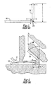
- a second, and perhaps more serious, disadvantage of these previously known hemming methods is that the formation of the flange 100 causes the aluminum panel to become more brittle along the bend line 104 between the flange 100 and the remainder of the outer panel 102.
- the subsequent final hemming operation causes a further compression of the flange 100 and movement of the flange 100 along its bend line 104.
- This further compression of the flange and movement along its bend line causes the aluminum panel to crack along the bend line during the hemming operation. Such cracking is unacceptable for the automotive industry as well as other industries.
- a still further disadvantage of the relatively large radius used to form the flange with the previously known hemming methods is that the final position of the bend line and thus the outer periphery of the final panel assembly will vary slightly following the hemming operation. Such movement of the bend line of the flange can result from either inward creeping of the bend line or outward compression of the flange bend line during the final hemming operation. Such movement of the outer bend line disadvantageously results in inconsistent gap spacing between adjacent panels on the resulting automotive vehicle.
- the method of the present invention first forms the flange along the outer periphery of the outer panel so that a bend line separates the flange from the remainder of the outer panel and also so that the flange lies in a plane substantially perpendicular to the plane of the remainder of the outer panel.
- the outer panel is positioned on the nest of a hemming machine in the conventional fashion.
- the inner panel is then positioned on the outer panel in the conventional fashion so that an outer periphery of the inner panel is adjacent to but spaced inwardly from the bend line around the outer panel.
- the nest is sequentially reciprocated relative to prehemming and final hemming tooling to hem the inner and outer panels together.
- the hemming method of the present invention utilizes a prehemming tooling having a radius R 2 of curvature preferably in the range of 2L > R 2 > 1/3 L where L equals the width of the flange.
- This high angle of impact between the curvilinear prehemming tool and the outer free edge of the flange of the present invention effectively imparts a force on the flange between the prehemming tool and in a direction towards the bend line between the flange and the remainder of the outer panel. In practice, this force effectively retains the bend line in a fixed position relative to the outer panel during the entire prehemming operation.
- the class "A" surface of the outer panel remains perfectly in contact with the anvil during the complete process of prehemming without performing any parasite bending in between the sharp bend to perform the flanging and the class "A” surface.
- the sharp bend early performed from flanging contributes at this turn to avoid any risk of class "A" surface buckling under the important axial force applied on the hem flange during the prehem operation.
- a traditional (1.2 mm + t) flanging rad will conduct to such situation, and preferably a 0.8 mm + t to 0.5 mm + t flanging rad will be preferred to generate during the prehem only one large curvature just above the initial bend and only the straight hem flange.
- the flange overlies a portion of the outer peripheral portion of the inner panel and is curvilinear in the shape conforming substantially to the shape of the prehemming tooling.
- final hemming tooling compresses the flange against the outer peripheral portion of the inner panel thus sandwiching the outer peripheral portion of the inner panel between the flange and the remainder of the outer panel and completing the hem for the final panel assembly.
- flat final hemming tooling will achieve the desired final appearance for the hem.
- the first part next to the initial hem bend of the large curvature performed on the flange during the prehem operation is curved even sharper by the compression of the final hem steel.
- the second part is flattened against the inner panel developing a spring-back force firmly trapping in position the inner panel.
- the present invention by its use not only of the initial flanging operation with a sharp bending radius between the flange and the remainder of the outer panel, but also by the use of the curvilinear prehemming tool, ensures that the outer bend line for the outer panel remains fixed during the entire hemming operation. By so fixing the position of the outer bend line, cracking of the outer panel along the bend line is avoided and panels of predictable and consistent sizes are obtained.
- the present invention eliminates essentially all creeping of the outer panel during the prehemming operation as well as any recoil resulting of this initial creeping when performing the final hem. By eliminating such creeping, the overall visual appearance of a very thin hem is obtained.
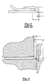
- a flange 10 is first formed around an outer peripheral portion of an outer panel 12. Consequently, the flange 10 extends from a bend line 14 formed in the outer panel 12 such that the flange 10 lies in a plane generally perpendicular to the plane of the remainder 16 of the outer panel 12.
- the flange 10, furthermore, has an overall width of L.
- the outer panel 12 is positioned on a nest 20 (illustrated only diagrammatically) of a hemming machine.
- An inner body panel 22 is then positioned on the outer panel 12 in a conventional fashion so that an outer edge 24 of the inner panel 22 is spaced slightly inwardly from the bend line 14 between the flange 10 and remaining portion 16 of the outer panel 12.
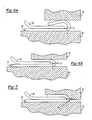
- the hemming method of the present invention utilizes a prehemming tool 26 having a curvilinear hemming surface 28 which is formed along the radius R 2 .
- the radius R 2 is in the range of 1/3 L to 2L where L equals the width of the flange 10.
- the prehemming tool 26 is positioned relative to the flange 10 so that, at the initial impact between an outer free edge 30 of the flange 10 and the hemming surface 28 of the prehemming tool 26, the angle of impact ⁇ is in the range of 55 degrees to 70 degrees and thus much greater than the previously known 45 degrees for prehemming tools.
- This increased angle ⁇ between the prehemming tool 26 and the flange 10 causes the prehemming tool 26 to compress the flange 10 in the direction from its free edge 30 towards its bend line 14 during the prehemming operation, i.e. as the prehemming tool 26 moves from the position shown in FIG. 5A and to the position shown in FIG. 5B.
- This compression thus ensures that the bend line 14, and thus the outer periphery of the final panel assembly, remains in a fixed position during the entire prehemming operation thereby eliminating the previously known "creeping" common to prior art hemming methods.
- the originally straight part of the flange 10 will be bent with a large bending curvature starting just above the initial flange bend.
- the flange 10 is bent so that it overlies an outer edge portion 40 of the inner panel 22. Furthermore, the flange 10 will build a large curvature inside of the prehemming tool 26 illustrated in FIG. 5A and FIG. 5B.
- the nest 20 is reciprocated relative to a final hemming tool 42 from the position shown in FIG. 6A and to the position shown in FIG. 6B.
- the final hemming tool 42 compresses the flange 10 thus sandwiching the outer edge portion 40 of the inner panel 22 between the flange 10 and the remainder 16 of the outer panel as shown in FIG. 6B.
- the final hemming tooling 42 has a flat hemming surface 44 which is generally parallel to the support surface of the nest 20.
- the use of a final hemming tool 42 with a flat hemming surface 44 is relatively inexpensive to manufacture and renders the inner and outer positions of the final hemming tool 42 relative to the flange 10 essentially noncritical.
- the final hemming tool 42 can include a shaped surface 46 (FIG. 7) such that the surface 46 corresponds in shape to the desired final hem.
- a primary advantage of the present invention is that, due to the sharp bend between the flange and the remainder of the outer panel accurately performed during the flanging operation coupled with the curvilinear prehemming tool, movement and further compression of the outer panel along its bend line is virtually eliminated. This, in turn, eliminates both creeping and recoil, as well as risk of cracking of the outer panel during the hemming operation.
Landscapes
- Engineering & Computer Science (AREA)
- Mechanical Engineering (AREA)
- Automobile Manufacture Line, Endless Track Vehicle, Trailer (AREA)
- Bending Of Plates, Rods, And Pipes (AREA)
- Body Structure For Vehicles (AREA)
- Rigid Containers With Two Or More Constituent Elements (AREA)
- Air Bags (AREA)
- Crystals, And After-Treatments Of Crystals (AREA)
- Semiconductor Lasers (AREA)
- Led Devices (AREA)
Claims (6)
- Verfahren zum Zusammenfügen zweier Metallplatten durch Falzen, bestehend aus folgenden Verfahrensschritten:Bildung eines Flansches (10) entlang einer Außenkante einer der Platten (12), sodass der Flansch von einer gebogenen Linie (14) zur Außenkante der einen Platte (12) verläuft und sodass der Flansch (10) auf einer Ebene (a) liegt, welche im Wesentlichen rechtwinklig zur Ebene (b) der einen Platte (12) ist,Anordnung einer Außenkante (24) der anderen Platte (22) anschließend an die gebogene Linie (14), wobei die Flansche (10) so gebogen werden, dass der Flansch die Außenkante (24) der anderen Platte (22) überdeckt, unddanach Zusammendrücken des Flansches (10) gegen einen äußeren Randbereich der anderen Platte (22), sodass der äußere Randbereich der anderen Platte (22) zwischen dem Flansch (10) und der anderen Platte (12) eingeklemmt ist,der Biegevorgang weiterhin den Verfahrensschritt beinhaltet, ein Vorfalzwerkzeug (26) mit gekrümmter Oberfläche gegen eine Außenkante des Flansches (10) einwirken zu lassen,
dadurch gekennzeichnet, dass
die gebogene Linie einen Außenradius (R) im Bereich von (1,0 mm + t) > R > (0,2 mm + t) aufweist, wobei t die Dicke der einen Platte in Millimetern darstellt,
und dass die gekrümmte Oberfläche des Vorfalzwerkzeugs einen solchen Radius und einen solche Auftreffstelle aufweist, dass der Winkel zwischen der Ebene des Flansches und einer Tangentialebene der gekrümmten Oberfläche des Vorfalzwerkzeugs beim erstmaligen Kontakt zwischen der gekrümmten Oberfläche des Vorfalzwerkzeugs und der Außenkante des Flansches im Bereich von 55 bis 70 Grad liegt. - Verfahren gemäß Anspruch 1, dadurch gekennzeichnet, dass es weiterhin den Verfahrensschritt enthält, beim Biegevorgang eine Kraft gleichzeitig auf die Ebene des Flansches (10) und rechtwinklig zur gebogenen Linie (14) auszuüben.
- Verfahren gemäß Anspruch 1 oder Anspruch 2, dadurch gekennzeichnet, dass der Biegevorgang weiterhin den Verfahrensschritt enthält, ein gekrümmtes Falzwerkzeug (42) gegen eine Außenkante des Flansches (10) einwirken zu lassen.
- Verfahren gemäß einem der vorhergehenden Ansprüche, dadurch gekennzeichnet, dass das Vorfalzwerkzeug (26) einen Radius (R2) im Bereich von 2L > R2 > 1/3L aufweist, wobei L die Breite des Flansches darstellt.
- Verfahren gemäß einem der vorhergehenden Ansprüche, dadurch gekennzeichnet, dass der Vorgang des Zusammendrückens weiterhin den Verfahrensschritt enthält, den Flansch (10) gegen ein planares Endfalzwerkzeug (42) zu drücken, das parallel zur Ebene der einen Platte (12) liegt.
- Verfahren gemäß einem der vorhergehenden Ansprüche, dadurch gekennzeichnet, dass der Vorgang des Zusammendrückens weiterhin den Verfahrensschritt enthält, den Flansch (10) gegen ein Endfalzwerkzeug (42) zu drücken, das ein Profil aufweist, welches dem Profil des gewünschten endgültigen Falzes zwischen zwei Platten (12, 22) entspricht.
Applications Claiming Priority (3)
| Application Number | Priority Date | Filing Date | Title |
|---|---|---|---|
| US133950 | 2002-04-26 | ||
| US10/133,950 US6739169B2 (en) | 2002-04-26 | 2002-04-26 | Method for hemming |
| PCT/IB2003/001548 WO2003090949A1 (en) | 2002-04-26 | 2003-04-24 | Method for hemming |
Publications (2)
| Publication Number | Publication Date |
|---|---|
| EP1503873A1 EP1503873A1 (de) | 2005-02-09 |
| EP1503873B1 true EP1503873B1 (de) | 2007-03-14 |
Family
ID=29249112
Family Applications (1)
| Application Number | Title | Priority Date | Filing Date |
|---|---|---|---|
| EP03717458A Expired - Lifetime EP1503873B1 (de) | 2002-04-26 | 2003-04-24 | Verfahren zur herstellung einer falzverbindung |
Country Status (12)
| Country | Link |
|---|---|
| US (2) | US6739169B2 (de) |
| EP (1) | EP1503873B1 (de) |
| JP (1) | JP2005523818A (de) |
| KR (1) | KR20050013542A (de) |
| AT (1) | ATE356677T1 (de) |
| AU (1) | AU2003222619A1 (de) |
| BR (1) | BR0309602A (de) |
| CA (1) | CA2483768C (de) |
| DE (1) | DE60312506T2 (de) |
| ES (1) | ES2282611T3 (de) |
| MX (1) | MXPA04010621A (de) |
| WO (1) | WO2003090949A1 (de) |
Families Citing this family (19)
| Publication number | Priority date | Publication date | Assignee | Title |
|---|---|---|---|---|
| FR2838359B1 (fr) * | 2002-04-15 | 2004-07-30 | Process Conception Ing Sa | Profil de lame de sertissage |
| US6928848B2 (en) * | 2003-03-27 | 2005-08-16 | Ford Motor Company | Flanging processes with radial compression of the blank stretched surface |
| EP1666171B1 (de) * | 2003-09-08 | 2008-11-12 | Sumitomo Light Metal Industries, Ltd. | Aluminiumlegierungsplattenglied mit falzteil |
| US20050177745A1 (en) * | 2004-02-11 | 2005-08-11 | Alio, Inc. | Distributed System and Methodology for Delivery of Media Content |
| US20050177853A1 (en) * | 2004-02-11 | 2005-08-11 | Alio, Inc. | System and Methodology for Distributed Delivery of Online Content in Response to Client Selections from an Online Catalog |
| JP4996907B2 (ja) * | 2006-10-20 | 2012-08-08 | 本田技研工業株式会社 | ローラヘミング加工方法 |
| US8106329B2 (en) * | 2007-05-18 | 2012-01-31 | Gsi Group Corporation | Laser processing of conductive links |
| CA2731377A1 (en) * | 2008-08-27 | 2010-03-04 | Ge Healthcare Bioscience Bioprocess Corp. | A system and method for manufacturing bed supports for chromatography columns |
| US8046197B2 (en) * | 2008-10-06 | 2011-10-25 | GM Global Technology Operations LLC | Method of designing a joint of adjacent components to minimize a perceived gap and algorithm for a computer-aided modeling system |
| US9339859B2 (en) | 2010-06-11 | 2016-05-17 | Thermal Structures, Inc. | Reciprocating devices for forming, folding, and/or hemming and methods therefor |
| US8875554B2 (en) | 2011-10-19 | 2014-11-04 | Ford Global Technologies, Llc | Hemming a flange with compression to form a sharp edge |
| US20140047889A1 (en) * | 2012-08-20 | 2014-02-20 | Ford Global Technologies, Llc | Method and Apparatus for Sharp Bending High Strength Panels |
| DE102014213063A1 (de) | 2014-07-04 | 2016-01-07 | Volkswagen Aktiengesellschaft | Verfahren und Werkzeugvorrichtung zum Herstellen einer Falzverbindung |
| DE102014213008A1 (de) | 2014-07-04 | 2016-01-07 | Volkswagen Aktiengesellschaft | Falzverbindung mit kleinem Falzradius, Bauteilverbund mit einer solchen Falzverbindung und Verfahren zur Herstellung |
| JP2016200889A (ja) * | 2015-04-08 | 2016-12-01 | ヒルタ工業株式会社 | ペダルアーム |
| CN106968406B (zh) * | 2017-03-22 | 2023-05-02 | 中国建筑第八工程局有限公司 | 金属板锁边装置及其使用方法 |
| JP7066431B2 (ja) * | 2018-02-06 | 2022-05-13 | トヨタ自動車九州株式会社 | ローラヘミング加工の仕上げ用ツールおよびローラヘミング加工装置 |
| JP7847030B2 (ja) * | 2022-04-28 | 2026-04-16 | 株式会社神戸製鋼所 | ヘミング加工品の製造方法 |
| GB2627994A (en) * | 2023-03-10 | 2024-09-11 | Jaguar Land Rover Ltd | Vehicle door aperture assembly |
Family Cites Families (6)
| Publication number | Priority date | Publication date | Assignee | Title |
|---|---|---|---|---|
| JPS5641032A (en) * | 1979-09-11 | 1981-04-17 | Sumitomo Light Metal Ind Ltd | Hemming method of aluminum or aluminum alloy plate |
| JPS5850130A (ja) * | 1981-09-22 | 1983-03-24 | Toyota Motor Corp | 縁曲端部成形方法及び縁曲端部成形装置 |
| NL1001786C2 (nl) * | 1995-11-30 | 1997-06-04 | Hoogovens Aluminium Bv | Werkwijze voor felsen en felsgereedschap. |
| DE19840637B4 (de) | 1998-09-05 | 2006-12-07 | Daimlerchrysler Ag | Verfahren zum Herstellen einer Falzverbindung zwischen einem Außenblech und einem Innenblech |
| US6257043B1 (en) * | 1999-12-30 | 2001-07-10 | Unova Ip Corp. | Modified flat hem apparatus and method |
| JP2001205365A (ja) * | 2000-01-18 | 2001-07-31 | Kobe Steel Ltd | アルミニウム合金板のヘミング加工方法 |
-
2002
- 2002-04-26 US US10/133,950 patent/US6739169B2/en not_active Expired - Lifetime
-
2003
- 2003-04-24 ES ES03717458T patent/ES2282611T3/es not_active Expired - Lifetime
- 2003-04-24 EP EP03717458A patent/EP1503873B1/de not_active Expired - Lifetime
- 2003-04-24 DE DE60312506T patent/DE60312506T2/de not_active Expired - Fee Related
- 2003-04-24 JP JP2003587562A patent/JP2005523818A/ja active Pending
- 2003-04-24 AU AU2003222619A patent/AU2003222619A1/en not_active Abandoned
- 2003-04-24 WO PCT/IB2003/001548 patent/WO2003090949A1/en not_active Ceased
- 2003-04-24 BR BR0309602-5A patent/BR0309602A/pt not_active Application Discontinuation
- 2003-04-24 KR KR10-2004-7017289A patent/KR20050013542A/ko not_active Withdrawn
- 2003-04-24 AT AT03717458T patent/ATE356677T1/de not_active IP Right Cessation
- 2003-04-24 CA CA2483768A patent/CA2483768C/en not_active Expired - Lifetime
- 2003-04-24 MX MXPA04010621A patent/MXPA04010621A/es active IP Right Grant
-
2004
- 2004-02-10 US US10/775,318 patent/US6907763B2/en not_active Expired - Lifetime
Also Published As
| Publication number | Publication date |
|---|---|
| CA2483768C (en) | 2010-07-13 |
| US6739169B2 (en) | 2004-05-25 |
| AU2003222619A1 (en) | 2003-11-10 |
| ATE356677T1 (de) | 2007-04-15 |
| JP2005523818A (ja) | 2005-08-11 |
| KR20050013542A (ko) | 2005-02-04 |
| CA2483768A1 (en) | 2003-11-06 |
| BR0309602A (pt) | 2005-02-15 |
| DE60312506D1 (de) | 2007-04-26 |
| ES2282611T3 (es) | 2007-10-16 |
| DE60312506T2 (de) | 2007-11-22 |
| MXPA04010621A (es) | 2005-02-14 |
| US20040159138A1 (en) | 2004-08-19 |
| WO2003090949A1 (en) | 2003-11-06 |
| US6907763B2 (en) | 2005-06-21 |
| US20030200782A1 (en) | 2003-10-30 |
| EP1503873A1 (de) | 2005-02-09 |
Similar Documents
| Publication | Publication Date | Title |
|---|---|---|
| US6739169B2 (en) | Method for hemming | |
| CA2736556C (en) | Closed structure parts, method and press forming apparatus for manufacturing the same | |
| US6928848B2 (en) | Flanging processes with radial compression of the blank stretched surface | |
| CA2738292C (en) | Closed structure parts, method and press forming apparatus for manufacturing the same | |
| CN101011929B (zh) | 面板紧固方法和用于汽车的面板部件 | |
| JP2013027894A (ja) | フレーム部品の製造方法及びフレーム部品 | |
| US20250050402A1 (en) | Working of sheet metal | |
| EP1611972B1 (de) | Verfahren und Vorrichtung zur Herstellung einer 180°-Falzverbindung | |
| KR20140131391A (ko) | 폐단면 구조 부품의 제조 방법 및 장치 | |
| JPH0238287B2 (de) | ||
| JP2004359137A (ja) | 車両用ドアのインパクトプロテクションビーム、その製造方法、およびu曲げ方法 | |
| JP2004130350A (ja) | アルミニウム合金自動車パネルの成形方法 | |
| CN120379778A (zh) | 金属板材加工 | |
| US6742372B2 (en) | Hemming machine | |
| EP1666171B1 (de) | Aluminiumlegierungsplattenglied mit falzteil | |
| RU2323057C2 (ru) | Способ гибки на прямой угол с малым радиусом | |
| JP2021062381A (ja) | 自動車用パネルの製造方法 | |
| GB2342607A (en) | Panel assembly | |
| JPH04138822A (ja) | 高張力鋼板のプレス成形方法 |
Legal Events
| Date | Code | Title | Description |
|---|---|---|---|
| PUAI | Public reference made under article 153(3) epc to a published international application that has entered the european phase |
Free format text: ORIGINAL CODE: 0009012 |
|
| 17P | Request for examination filed |
Effective date: 20041125 |
|
| AK | Designated contracting states |
Kind code of ref document: A1 Designated state(s): AT BE BG CH CY CZ DE DK EE ES FI FR GB GR HU IE IT LI LU MC NL PT RO SE SI SK TR |
|
| AX | Request for extension of the european patent |
Extension state: AL LT LV MK |
|
| GRAP | Despatch of communication of intention to grant a patent |
Free format text: ORIGINAL CODE: EPIDOSNIGR1 |
|
| GRAS | Grant fee paid |
Free format text: ORIGINAL CODE: EPIDOSNIGR3 |
|
| GRAA | (expected) grant |
Free format text: ORIGINAL CODE: 0009210 |
|
| AK | Designated contracting states |
Kind code of ref document: B1 Designated state(s): AT BE BG CH CY CZ DE DK EE ES FI FR GB GR HU IE IT LI LU MC NL PT RO SE SI SK TR |
|
| PG25 | Lapsed in a contracting state [announced via postgrant information from national office to epo] |
Ref country code: SI Free format text: LAPSE BECAUSE OF FAILURE TO SUBMIT A TRANSLATION OF THE DESCRIPTION OR TO PAY THE FEE WITHIN THE PRESCRIBED TIME-LIMIT Effective date: 20070314 Ref country code: BE Free format text: LAPSE BECAUSE OF FAILURE TO SUBMIT A TRANSLATION OF THE DESCRIPTION OR TO PAY THE FEE WITHIN THE PRESCRIBED TIME-LIMIT Effective date: 20070314 Ref country code: CH Free format text: LAPSE BECAUSE OF FAILURE TO SUBMIT A TRANSLATION OF THE DESCRIPTION OR TO PAY THE FEE WITHIN THE PRESCRIBED TIME-LIMIT Effective date: 20070314 Ref country code: FI Free format text: LAPSE BECAUSE OF FAILURE TO SUBMIT A TRANSLATION OF THE DESCRIPTION OR TO PAY THE FEE WITHIN THE PRESCRIBED TIME-LIMIT Effective date: 20070314 Ref country code: LI Free format text: LAPSE BECAUSE OF FAILURE TO SUBMIT A TRANSLATION OF THE DESCRIPTION OR TO PAY THE FEE WITHIN THE PRESCRIBED TIME-LIMIT Effective date: 20070314 |
|
| REG | Reference to a national code |
Ref country code: GB Ref legal event code: FG4D |
|
| RIN1 | Information on inventor provided before grant (corrected) |
Inventor name: BAULIER, DOMINIQUE |
|
| REG | Reference to a national code |
Ref country code: CH Ref legal event code: EP |
|
| PGFP | Annual fee paid to national office [announced via postgrant information from national office to epo] |
Ref country code: DE Payment date: 20070419 Year of fee payment: 5 |
|
| PGFP | Annual fee paid to national office [announced via postgrant information from national office to epo] |
Ref country code: SE Payment date: 20070420 Year of fee payment: 5 |
|
| PGFP | Annual fee paid to national office [announced via postgrant information from national office to epo] |
Ref country code: ES Payment date: 20070426 Year of fee payment: 5 |
|
| REF | Corresponds to: |
Ref document number: 60312506 Country of ref document: DE Date of ref document: 20070426 Kind code of ref document: P |
|
| PGFP | Annual fee paid to national office [announced via postgrant information from national office to epo] |
Ref country code: AT Payment date: 20070430 Year of fee payment: 5 Ref country code: NL Payment date: 20070430 Year of fee payment: 5 |
|
| REG | Reference to a national code |
Ref country code: IE Ref legal event code: FG4D |
|
| PGFP | Annual fee paid to national office [announced via postgrant information from national office to epo] |
Ref country code: HU Payment date: 20070530 Year of fee payment: 5 |
|
| REG | Reference to a national code |
Ref country code: SE Ref legal event code: TRGR |
|
| PG25 | Lapsed in a contracting state [announced via postgrant information from national office to epo] |
Ref country code: PT Free format text: LAPSE BECAUSE OF FAILURE TO SUBMIT A TRANSLATION OF THE DESCRIPTION OR TO PAY THE FEE WITHIN THE PRESCRIBED TIME-LIMIT Effective date: 20070814 |
|
| ET | Fr: translation filed | ||
| REG | Reference to a national code |
Ref country code: CH Ref legal event code: PL Ref country code: HU Ref legal event code: AG4A Ref document number: E001888 Country of ref document: HU |
|
| REG | Reference to a national code |
Ref country code: ES Ref legal event code: FG2A Ref document number: 2282611 Country of ref document: ES Kind code of ref document: T3 |
|
| PGFP | Annual fee paid to national office [announced via postgrant information from national office to epo] |
Ref country code: GB Payment date: 20070417 Year of fee payment: 5 Ref country code: SK Payment date: 20070614 Year of fee payment: 5 |
|
| PG25 | Lapsed in a contracting state [announced via postgrant information from national office to epo] |
Ref country code: RO Free format text: LAPSE BECAUSE OF FAILURE TO SUBMIT A TRANSLATION OF THE DESCRIPTION OR TO PAY THE FEE WITHIN THE PRESCRIBED TIME-LIMIT Effective date: 20070314 |
|
| PGFP | Annual fee paid to national office [announced via postgrant information from national office to epo] |
Ref country code: CZ Payment date: 20070418 Year of fee payment: 5 Ref country code: IT Payment date: 20070621 Year of fee payment: 5 |
|
| PLBE | No opposition filed within time limit |
Free format text: ORIGINAL CODE: 0009261 |
|
| STAA | Information on the status of an ep patent application or granted ep patent |
Free format text: STATUS: NO OPPOSITION FILED WITHIN TIME LIMIT |
|
| PG25 | Lapsed in a contracting state [announced via postgrant information from national office to epo] |
Ref country code: DK Free format text: LAPSE BECAUSE OF FAILURE TO SUBMIT A TRANSLATION OF THE DESCRIPTION OR TO PAY THE FEE WITHIN THE PRESCRIBED TIME-LIMIT Effective date: 20070314 |
|
| 26N | No opposition filed |
Effective date: 20071217 |
|
| PG25 | Lapsed in a contracting state [announced via postgrant information from national office to epo] |
Ref country code: GR Free format text: LAPSE BECAUSE OF FAILURE TO SUBMIT A TRANSLATION OF THE DESCRIPTION OR TO PAY THE FEE WITHIN THE PRESCRIBED TIME-LIMIT Effective date: 20070615 |
|
| PGFP | Annual fee paid to national office [announced via postgrant information from national office to epo] |
Ref country code: FR Payment date: 20070426 Year of fee payment: 5 |
|
| PG25 | Lapsed in a contracting state [announced via postgrant information from national office to epo] |
Ref country code: IE Free format text: LAPSE BECAUSE OF NON-PAYMENT OF DUE FEES Effective date: 20070424 |
|
| EUG | Se: european patent has lapsed | ||
| GBPC | Gb: european patent ceased through non-payment of renewal fee |
Effective date: 20080424 |
|
| NLV4 | Nl: lapsed or anulled due to non-payment of the annual fee |
Effective date: 20081101 |
|
| PG25 | Lapsed in a contracting state [announced via postgrant information from national office to epo] |
Ref country code: HU Free format text: LAPSE BECAUSE OF NON-PAYMENT OF DUE FEES Effective date: 20080425 Ref country code: NL Free format text: LAPSE BECAUSE OF NON-PAYMENT OF DUE FEES Effective date: 20081101 Ref country code: DE Free format text: LAPSE BECAUSE OF NON-PAYMENT OF DUE FEES Effective date: 20081101 Ref country code: EE Free format text: LAPSE BECAUSE OF FAILURE TO SUBMIT A TRANSLATION OF THE DESCRIPTION OR TO PAY THE FEE WITHIN THE PRESCRIBED TIME-LIMIT Effective date: 20070314 |
|
| PG25 | Lapsed in a contracting state [announced via postgrant information from national office to epo] |
Ref country code: SK Free format text: LAPSE BECAUSE OF NON-PAYMENT OF DUE FEES Effective date: 20080424 Ref country code: AT Free format text: LAPSE BECAUSE OF NON-PAYMENT OF DUE FEES Effective date: 20080424 |
|
| PG25 | Lapsed in a contracting state [announced via postgrant information from national office to epo] |
Ref country code: MC Free format text: LAPSE BECAUSE OF NON-PAYMENT OF DUE FEES Effective date: 20070430 |
|
| PG25 | Lapsed in a contracting state [announced via postgrant information from national office to epo] |
Ref country code: CZ Free format text: LAPSE BECAUSE OF NON-PAYMENT OF DUE FEES Effective date: 20080424 |
|
| REG | Reference to a national code |
Ref country code: ES Ref legal event code: FD2A Effective date: 20080425 |
|
| PG25 | Lapsed in a contracting state [announced via postgrant information from national office to epo] |
Ref country code: GB Free format text: LAPSE BECAUSE OF NON-PAYMENT OF DUE FEES Effective date: 20080424 |
|
| PG25 | Lapsed in a contracting state [announced via postgrant information from national office to epo] |
Ref country code: ES Free format text: LAPSE BECAUSE OF NON-PAYMENT OF DUE FEES Effective date: 20080425 Ref country code: CY Free format text: LAPSE BECAUSE OF FAILURE TO SUBMIT A TRANSLATION OF THE DESCRIPTION OR TO PAY THE FEE WITHIN THE PRESCRIBED TIME-LIMIT Effective date: 20070314 |
|
| PG25 | Lapsed in a contracting state [announced via postgrant information from national office to epo] |
Ref country code: BG Free format text: LAPSE BECAUSE OF FAILURE TO SUBMIT A TRANSLATION OF THE DESCRIPTION OR TO PAY THE FEE WITHIN THE PRESCRIBED TIME-LIMIT Effective date: 20070614 Ref country code: IT Free format text: LAPSE BECAUSE OF NON-PAYMENT OF DUE FEES Effective date: 20080424 Ref country code: LU Free format text: LAPSE BECAUSE OF NON-PAYMENT OF DUE FEES Effective date: 20070424 |
|
| PG25 | Lapsed in a contracting state [announced via postgrant information from national office to epo] |
Ref country code: TR Free format text: LAPSE BECAUSE OF FAILURE TO SUBMIT A TRANSLATION OF THE DESCRIPTION OR TO PAY THE FEE WITHIN THE PRESCRIBED TIME-LIMIT Effective date: 20070314 |
|
| PG25 | Lapsed in a contracting state [announced via postgrant information from national office to epo] |
Ref country code: SE Free format text: LAPSE BECAUSE OF NON-PAYMENT OF DUE FEES Effective date: 20080425 |
|
| REG | Reference to a national code |
Ref country code: FR Ref legal event code: ST Effective date: 20111202 |
|
| PG25 | Lapsed in a contracting state [announced via postgrant information from national office to epo] |
Ref country code: FR Free format text: LAPSE BECAUSE OF NON-PAYMENT OF DUE FEES Effective date: 20080430 |