EP1503820B1 - Distributeur con u pour dispositif de perfusion - Google Patents
Distributeur con u pour dispositif de perfusion Download PDFInfo
- Publication number
- EP1503820B1 EP1503820B1 EP03728316A EP03728316A EP1503820B1 EP 1503820 B1 EP1503820 B1 EP 1503820B1 EP 03728316 A EP03728316 A EP 03728316A EP 03728316 A EP03728316 A EP 03728316A EP 1503820 B1 EP1503820 B1 EP 1503820B1
- Authority
- EP
- European Patent Office
- Prior art keywords
- lead screw
- shape memory
- memory element
- length
- reservoir
- Prior art date
- Legal status (The legal status is an assumption and is not a legal conclusion. Google has not performed a legal analysis and makes no representation as to the accuracy of the status listed.)
- Expired - Lifetime
Links
Images


Classifications
-
- A—HUMAN NECESSITIES
- A61—MEDICAL OR VETERINARY SCIENCE; HYGIENE
- A61M—DEVICES FOR INTRODUCING MEDIA INTO, OR ONTO, THE BODY; DEVICES FOR TRANSDUCING BODY MEDIA OR FOR TAKING MEDIA FROM THE BODY; DEVICES FOR PRODUCING OR ENDING SLEEP OR STUPOR
- A61M5/00—Devices for bringing media into the body in a subcutaneous, intra-vascular or intramuscular way; Accessories therefor, e.g. filling or cleaning devices, arm-rests
- A61M5/14—Infusion devices, e.g. infusing by gravity; Blood infusion; Accessories therefor
- A61M5/142—Pressure infusion, e.g. using pumps
- A61M5/145—Pressure infusion, e.g. using pumps using pressurised reservoirs, e.g. pressurised by means of pistons
- A61M5/1452—Pressure infusion, e.g. using pumps using pressurised reservoirs, e.g. pressurised by means of pistons pressurised by means of pistons
-
- A—HUMAN NECESSITIES
- A61—MEDICAL OR VETERINARY SCIENCE; HYGIENE
- A61M—DEVICES FOR INTRODUCING MEDIA INTO, OR ONTO, THE BODY; DEVICES FOR TRANSDUCING BODY MEDIA OR FOR TAKING MEDIA FROM THE BODY; DEVICES FOR PRODUCING OR ENDING SLEEP OR STUPOR
- A61M5/00—Devices for bringing media into the body in a subcutaneous, intra-vascular or intramuscular way; Accessories therefor, e.g. filling or cleaning devices, arm-rests
- A61M5/14—Infusion devices, e.g. infusing by gravity; Blood infusion; Accessories therefor
- A61M5/142—Pressure infusion, e.g. using pumps
- A61M5/145—Pressure infusion, e.g. using pumps using pressurised reservoirs, e.g. pressurised by means of pistons
- A61M2005/14506—Pressure infusion, e.g. using pumps using pressurised reservoirs, e.g. pressurised by means of pistons mechanically driven, e.g. spring or clockwork
-
- A—HUMAN NECESSITIES
- A61—MEDICAL OR VETERINARY SCIENCE; HYGIENE
- A61M—DEVICES FOR INTRODUCING MEDIA INTO, OR ONTO, THE BODY; DEVICES FOR TRANSDUCING BODY MEDIA OR FOR TAKING MEDIA FROM THE BODY; DEVICES FOR PRODUCING OR ENDING SLEEP OR STUPOR
- A61M2205/00—General characteristics of the apparatus
- A61M2205/02—General characteristics of the apparatus characterised by a particular materials
- A61M2205/0266—Shape memory materials
-
- A—HUMAN NECESSITIES
- A61—MEDICAL OR VETERINARY SCIENCE; HYGIENE
- A61M—DEVICES FOR INTRODUCING MEDIA INTO, OR ONTO, THE BODY; DEVICES FOR TRANSDUCING BODY MEDIA OR FOR TAKING MEDIA FROM THE BODY; DEVICES FOR PRODUCING OR ENDING SLEEP OR STUPOR
- A61M2205/00—General characteristics of the apparatus
- A61M2205/35—Communication
- A61M2205/3576—Communication with non implanted data transmission devices, e.g. using external transmitter or receiver
- A61M2205/3592—Communication with non implanted data transmission devices, e.g. using external transmitter or receiver using telemetric means, e.g. radio or optical transmission
Definitions
- the present invention relates generally to medical devices, systems and methods, and more particularly to small, low cost, portable infusion devices and methods that are useable to achieve precise, sophisticated, and programmable flow patterns for the delivery of therapeutic liquids such as insulin to a mammalian patient. Even more particularly, the present invention is directed to a dispenser for a fluid delivery device that utilizes a shape memory element.
- a medicine may only be available in a liquid form, or the liquid version may have desirable characteristics that cannot be achieved with solid or pill form. Delivery of liquid medicines may best be accomplished by infusing directly into the cardiovascular system via veins or arteries, into the subcutaneous tissue or directly into organs, tumors, cavities, bones or other site specific locations within the body.
- Ambulatory infusion pumps have been developed for delivering liquid medicaments to a patient. These infusion devices have the ability to offer sophisticated fluid delivery profiles accomplishing bolus requirements, continuous infusion and variable flow rate delivery. These infusion capabilities usually result in better efficacy of the drug and therapy and less toxicity to the patient's system.
- An example of a use of an ambulatory infusion pump is for the delivery of insulin for the treatment of diabetes mellitus. These pumps can deliver insulin on a continuous basal basis as well as a bolus basis as is disclosed in U.S. Patent 4,498,843 to Schneider et al .
- the ambulatory pumps often work with a reservoir to contain the liquid medicine, such as a cartridge, a syringe or an IV bag, and use electro-mechanical pumping or metering technology to deliver the medication to the patient via tubing from the infusion device to a needle that is inserted transcutaneously, or through the skin of the patient.
- the devices allow control and programming via electromechanical buttons or switches located on the housing of the device, and accessed by the patient or clinician.
- the devices include visual feedback via text or graphic screens, such as liquid crystal displays known as LCD's, and may include alert or warning lights and audio or vibration signals and alarms.
- the device can be worn in a harness or pocket or strapped to the body of the patient.
- the applicant of the present application provided a small, low cost, light-weight, easy-to-use device for delivering liquid medicines to a patient.
- the device which is described in detail in co-pending U.S. application serial No. 09/943,992, filed on August 31, 2001 , includes an exit port, a dispenser for causing fluid from a reservoir to flow to the exit port, a local processor programmed to cause a flow of fluid to the exit port based on flow instructions from a separate, remote control device, and a wireless receiver connected to the local processor for receiving the flow instructions.
- the device is provided with a housing that is free of user input components, such as a keypad, for providing flow instructions to the local processor.
- the components will be simple in design, and relatively compact, lightweight, easy to manufacture and inexpensive, such that the resulting fluid delivery device can be effective, yet inexpensive and disposable.
- the present invention provides a device for delivering fluid, such as insulin for example, to a patient.
- the device includes an exit port assembly, a reservoir including a side wall extending towards an outlet connected to the exit port assembly, and a threaded lead screw received in the reservoir and extending towards the outlet of the reservoir.
- a plunger is secured to the lead screw and has an outer periphery linearly slideable along the side wall of the reservoir. The plunger and the lead screw are operatively arranged such that rotation of the lead screw in a first direction causes the plunger to slide along the side wall towards the outlet of the reservoir, which in turn causes fluid within the reservoir to be dispensed to the exit port assembly.
- the device also includes a dispenser having a shape memory element having a changeable length decreasing from an uncharged length to a charged length when at least one charge is applied to the shape memory element.
- the shape memory element has a first end secured to the lead screw, a portion of the elongated shape memory element wrapped around the lead screw, and a second end fixed with respect to the lead screw, such that the changeable length of the shape memory element decreasing from an uncharged length to a charged length causes rotation of the lead screw in the first direction.
- the use of a shape memory element helps provide a dispenser that is simple in design, and relatively compact, lightweight, and easy to manufacture.
- the present invention provides another device for delivering fluid.
- the device includes an exit port assembly, a reservoir having a side wall extending towards an outlet connected to the exit port assembly, and a threaded lead screw received in the reservoir.
- a plunger is secured to the lead screw and has an outer periphery linearly slideable along the side wall of the reservoir.
- the plunger and the lead screw are operatively arranged such that rotation of the lead screw in a first direction causes the plunger to slide along the side wall towards the outlet of the reservoir.
- the device also includes a ratchet mechanism secured to the lead screw and including a wheel arranged such that rotation of the wheel in the first direction causes rotation of the lead screw in the first direction, while rotation of the wheel in a second direction causes no rotation of the lead screw.
- the device further includes a dispenser includes an elongated shape memory element having a changeable length decreasing from an uncharged length to a charged length when at least one charge is applied to the shape memory element.
- the shape memory element operatively connected to the wheel of the ratchet mechanism such that the changeable length of the shape memory element decreasing from an uncharged length to a charged length causes rotation of the wheel in one of the first direction and the second direction.
- An actuation element is secured to the wheel for moving the wheel in the other of the first direction and the second direction.
- the present invention provides an additional device for delivering fluid.
- the device includes an exit port assembly, a reservoir including a side wall extending towards an outlet connected to the exit port assembly, and a threaded lead screw received in the reservoir.
- a plunger is secured to the lead screw and has an outer periphery linearly slideable along the side wall of the reservoir. The plunger and the lead screw are operatively arranged such that rotation of the lead screw in a first direction causes the plunger to slide along the side wall towards the outlet of the reservoir.
- a gear is secured to the lead screw and has radially extending teeth positioned to contact a first fixed member and prevent rotation of the gear and the lead screw in the second direction.
- the device also includes a dispenser having a slide positioned for linear movement adjacent the gear between a second fixed member and a third fixed member.
- the slide has a finger for engaging the teeth of the gear.
- the finger and the teeth are adapted such that linear movement of the slide past the gear towards the second fixed member causes rotation of the gear in the first direction, while linear movement of the slide past the gear towards the third fixed member causes no rotation of the gear.
- the dispenser further includes an elongated shape memory element having a changeable length decreasing from an uncharged length to a charged length when at least one charge is applied to the shape memory element.
- the shape memory element is connected between the slide and the third fixed member such that the changeable length of the shape memory element decreasing from an uncharged length to a charged length causes linear movement of the slide past the gear towards the third fixed member.
- An actuation element is connected between the slide and the second fixed member for causing linear movement of the slide past the gear towards the second fixed member when the charge applied to the shape memory element is removed.
- the present invention provides a further device for delivering fluid.
- the device includes an exit port assembly, a reservoir including a side wall extending towards an outlet connected to the exit port assembly, and a threaded lead screw received in the reservoir.
- a plunger is secured to the lead screw and has an outer periphery linearly slideable along the side wall of the reservoir. The plunger and the lead screw are operatively arranged such that rotation of the lead screw in a first direction causes the plunger to slide along the side wall towards the outlet of the reservoir.
- a gear is secured to the lead screw and includes radially extending teeth positioned to contact a first fixed member and prevent rotation of the gear and the lead screw in the second direction.
- the device also includes a dispenser having a slide positioned for linear movement between the gear and a second fixed member, the slide including a finger for engaging the teeth of the gear.
- the finger and the teeth are adapted such that linear movement of the slide towards the gear causes rotation of the gear in the first direction while linear movement of the slide towards the second fixed member causes no rotation of the gear.
- the dispenser further includes an elongated shape memory element having a changeable length decreasing from an uncharged length to a charged length when at least one charge is applied to the shape memory element, the shape memory element connected between the slide and the second fixed member such that the changeable length of the shape memory element decreasing from an uncharged length to a charged length causes linear movement of the slide towards the second fixed member.
- An actuation element is connected between the slide and the second fixed member for causing linear movement of the slide towards the gear.
- the present invention therefore, provides a device for delivering fluid to a patient including new and improved components, such as dispensers and reservoirs.
- the components are simple in design, and relatively compact, lightweight, easy to manufacture and inexpensive, such that the resulting fluid delivery device is also relatively compact, lightweight, easy to manufacture and inexpensive such that the device can be inexpensive and disposable.
- the new and improved components of the present invention advantageously use shape memory elements to reduce complexity and costs.
- the present invention provides still another device for delivering fluid.
- the device includes an exit port assembly, a fill port, and a reservoir including a side wall extending towards an outlet connected to the exit port assembly and an inlet connected to the fill port.
- a threaded lead screw is received in the reservoir and extends towards the outlet, and a plunger has an outer periphery slidably received on the side wall of the reservoir and an inner periphery slidably received on the lead screw.
- the plunger is non-rotatable with respect to the side wall and includes an insert having a threaded surface mateable with the threaded lead screw, and a spring biasing the threaded surface of the insert against the threaded lead screw such that rotating the lead screw in a first direction causes the plunger to slide along the side wall towards the outlet of the reservoir.
- the plunger also includes an elongated shape memory element having a first end secured to the insert and a second end extending radially outwardly from the insert and secured to the plunger, such that the changeable length of the shape memory element decreasing from an uncharged length to a charged length pulls the threaded surface of the insert away from the threaded lead screw. Applying a charge to the shape memory element, therefore, disengages the insert and allows the plunger to slide along the lead screw and away from the inlet of the reservoir during filling of the reservoir.
- the present invention provides yet another device for delivering fluid.
- the device includes an exit port assembly, a fill port, a reservoir including a side wall extending towards an outlet connected to the exit port assembly and an inlet connected to the fill port, and a threaded lead screw received at least partly within the reservoir.
- a linearly fixed, annular gear is coaxially positioned on the threaded lead screw adjacent the reservoir and includes an insert having a threaded surface mateable with the threaded lead screw, a spring biasing the threaded surface of the insert against the threaded lead screw such that rotating the gear in a first direction causes the lead screw to move linearly towards the outlet of the reservoir, and an elongated shape memory element having a first end secured to the insert and a second end extending radially outwardly from the insert and secured to the gear.
- a changeable length of the shape memory element decreasing from an uncharged length to a charged length pulls the threaded surface of the insert away from the threaded lead screw such that the lead screw is movable linearly through the gear and away from the inlet of the reservoir.
- a plunger is secured to the lead screw and has an outer periphery linearly slideable along the side wall of the reservoir. During filling of the reservoir, the shape memory element can be charged to allow the plunger and lead screw to moved away from the fill port and the inlet of the reservoir.
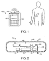
- Fig. 1 is a perspective view of a first exemplary embodiment of a fluid delivery device constructed in accordance with the present invention and shown secured on a patient, and a remote control device for use with the fluid delivery device (the remote control device being enlarged with respect to the patient and the fluid delivery device for purposes of illustration);
- Fig. 2 is a sectional side view of the fluid delivery device of Fig. 1 ;
- Fig. 3 is a sectional side view of an exemplary embodiment of a reservoir, a plunger and a lead screw of the fluid delivery device of Fig. 1 , and an exemplary embodiment of a dispenser constructed in accordance with the present invention for turning the lead screw;
- Fig. 4 is an enlarged sectional view of the plunger and the lead screw of the fluid delivery device of Fig. 1 ;
- Fig. 5 is a sectional view of the reservoir, the plunger and the lead screw of the fluid delivery device of Fig. 1 taken along line 5--5 of Fig. 3 ;
- Fig. 6 is an end elevation view, partially in section, of the dispenser for turning the lead screw of the fluid delivery device of Fig. 1 ;
- Fig. 7 is a first end elevation view, partially in section, of another exemplary embodiment of a dispenser constructed in accordance with the present invention for turning the lead screw of the fluid delivery device of Fig. 1 ;
- Figs. 8 and 9 are schematic second end elevation views illustrating operation of the dispenser of Fig. 7 ;
- Figs. 10 through 12 are schematic end elevation views, partially in section, illustrating operation of an additional exemplary embodiment of a dispenser constructed in accordance with the present invention for turning the lead screw of the fluid delivery device of Fig. 1 ;
- Figs. 13 through 15 are schematic end elevation views, partially in section, illustrating operation of a further exemplary embodiment of a dispenser constructed in accordance with the present invention for turning the lead screw of the fluid delivery device of Fig. 1 ;
- Figs. 16 through 19 are side elevation views, partially in section, illustrating operation of still another exemplary embodiment of a dispenser constructed in accordance with the present invention for turning the lead screw of the fluid delivery device of Fig. 1 ;
- Figs. 20 and 21 are top plan views, partially in section, of an auxiliary component, illustrating actuation of the component
- Fig. 22 is a top sectional view of another exemplary embodiment of a fluid delivery device constructed in accordance with the present invention.
- Figs. 23 and 24 are enlarged views of the portion of the fluid delivery device contained in circle "23 & 24" of Fig. 22 illustrating operation of a plunger of the device;
- Fig. 25 is a side elevation view, partially in section, of still other exemplary embodiments of a dispenser and a reservoir constructed in accordance with the present invention for use as part of a fluid delivery device, such as the fluid delivery device of Fig. 1 .
- a fluid delivery device 10 including a dispenser 40 constructed in accordance with the present invention.
- the dispenser 40 causes fluid flow between a reservoir 30 and an exit port assembly 70 during operation of the device 10.
- shape memory elements are utilized in accordance with the present invention to provide effective, yet simple and inexpensive dispensers for fluid delivery devices.
- the fluid delivery device 10 of Fig. 2 can be used for the delivery of fluids to a person or animal.
- the types of liquids that can be delivered by the fluid delivery device 10 include, but are not limited to, insulin, antibiotics, nutritional fluids, total parenteral nutrition or TPN, analgesics, morphine, hormones or hormonal drugs, gene therapy drugs, anticoagulants, analgesics, cardiovascular medications, AZT or chemotherapeutics.
- the types of medical conditions that the fluid delivery device 10 might be used to treat include, but are not limited to, diabetes, cardiovascular disease, pain, chronic pain, cancer, AIDS, neurological diseases, Alzheimer's Disease, ALS, Hepatitis, Parkinson's Disease or spasticity.
- the dispenser 40 according to the present invention can be used with fluid delivery devices other than those used for the delivery of fluids to persons or animals.
- the fluid delivery device 10 also includes a processor or electronic microcontroller (hereinafter referred to as the "local" processor) 50 connected to the dispenser 40.
- the local processor 50 is programmed to cause a flow of fluid to the exit port assembly 70 based on flow instructions from a separate, remote control device 100, an example of which is shown in Fig. 1 .
- the fluid delivery device 10 further includes a wireless receiver 60 connected to the local processor 50 for receiving the flow instructions from the separate, remote control device 100 and delivering the flow instructions to the local processor.
- the device 10 also includes a housing 20 containing the exit port assembly 70, the reservoir 30, the dispenser 40, the local processor 50 and the wireless receiver 60.
- the housing 20 of the fluid delivery device 10 is free of user input components for providing flow instructions to the local processor 50, such as electromechanical switches or buttons on an outer surface 21 of the housing, or interfaces otherwise accessible to a user to adjust the programmed flow rate through the local processor 50.
- the lack of user input components allows the size, complexity and costs of the device 10 to be substantially reduced so that the device 10 lends itself to being small and disposable in nature. Examples of such devices are disclosed in co-pending U.S. patent application serial number 09/943,992, filed on August 31, 2001 (Atty. Docket No. INSL-110), and entitled DEVICES, SYSTEMS AND METHODS FOR PATIENT INFUSION, which is assigned to the assignee of the present application.
- the fluid delivery device 10 includes the wireless communication element, or receiver 60 for receiving the user inputs from the separate, remote control device 100 of Fig. 1 .
- Signals can be sent via a communication element (not shown) of the remote control device 100, which can include or be connected to an antenna 130, shown in Fig. 1 as being external to the device 100.
- the remote control device 100 has user input components, including an array of electromechanical switches, such as the membrane keypad 120 shown.
- the control device 100 also includes user output components, including a visual display, such as a liquid crystal display (LCD) 110.
- a visual display such as a liquid crystal display (LCD) 110.
- the control device can be provided with a touch screen for both user input and output.
- the remote control device 100 has its own processor (hereinafter referred to as the "remote" processor) connected to the membrane keypad 120 and the LCD 110.
- the remote processor receives the user inputs from the membrane keypad 120 and provides "flow" instructions for transmission to the fluid delivery device 10, and provides information to the LCD 110. Since the remote control device 100 also includes a visual display 110, the fluid delivery device 10 can be void of an information screen, further reducing the size, complexity and costs of the device 10.
- the communication element 60 of the device 10 preferably receives electronic communication from the remote control device 100 using radio frequency or other wireless communication standards and protocols.
- the communication element 60 is a two-way communication element, including a receiver and a transmitter, for allowing the fluid delivery device 10 to send information back to the remote control device 100.
- the remote control device 100 also includes an integral communication element comprising a receiver and a transmitter, for allowing the remote control device 100 to receive the information sent by the fluid delivery device 10.
- the local processor 50 of the device 10 contains all the computer programs and electronic circuitry needed to allow a user to program the desired flow patterns and adjust the program as necessary.
- Such circuitry can include one or more microprocessors, digital and analog integrated circuits, resistors, capacitors, transistors and other semiconductors and other electronic components known to those skilled in the art.
- the local processor 50 also includes programming, electronic circuitry and memory to properly activate the dispenser 40 at the needed time intervals.
- the device 10 includes a power supply 80, such as a battery or capacitor, for supplying power to the local processor 50.
- the power supply 80 is preferably integrated into the fluid delivery device 10, but can be provided as replaceable, e.g., a replaceable battery.
- the device 10 can include sensors or transducers such as a reservoir volume transducer or a reservoir pressure transducer, for transmitting information to the local processor 50 to indicate how and when to activate the dispenser 40, or to indicate other parameters determining flow, pump flow path prime condition, blockage in flow path, contact sensors, rotary motion or other motion indicators, as well as conditions such as the reservoir 30 being empty or leaking, or the dispensing of too much or too little fluid from the reservoir, etc.
- sensors or transducers such as a reservoir volume transducer or a reservoir pressure transducer, for transmitting information to the local processor 50 to indicate how and when to activate the dispenser 40, or to indicate other parameters determining flow, pump flow path prime condition, blockage in flow path, contact sensors, rotary motion or other motion indicators, as well as conditions such as the reservoir 30 being empty or leaking, or the dispensing of too much or too little fluid from the reservoir, etc.
- the volume of the reservoir 30 is chosen to best suit the therapeutic application of the fluid delivery device 10 impacted by such factors as available concentrations of medicinal fluids to be delivered, acceptable times between refills or disposal of the fluid delivery device 10, size constraints and other factors.
- the reservoir 30 may be prefilled by the device manufacturer or a cooperating drug manufacturer, or may include external filling means, such as a fill port having needle insertion septum or a Luer connector, for example.
- the device 10 can be provided with a removable reservoir.
- the exit port assembly 70 can include elements to penetrate the skin of the patient, such that the entire volume of the flow path 210 of the fluid delivery device 10 is predetermined.
- a needle-connection tubing terminating in a skin penetrating cannula can be provided as an integral part of the exit port assembly 70, with the skin penetrating cannula comprising a rigid member, such as a needle.
- the exit port assembly 70 can further be provided with injection means, such as a spring driven mechanism, to assist in penetrating the skin with the skin penetrating cannula.
- the cannula is a flexible tube
- a rigid penetrator within the lumen of the tube can be driven through the skin by the injection means and then withdrawn, leaving the soft cannula in place in the subcutaneous tissue of the patient or other internal site.
- the injection means may be integral to the device 10, or removable soon after transcutaneous penetration.
- the exit port assembly 70 can be adapted to connect, with a Luer connector for example, to a separate, standard infusion device that includes a skin penetrating cannula.
- the exit port assembly 70 can also be provided with a removable plug (not shown) for preventing leakage during storage and shipment if prefilled, and during priming if filled by user, and prior to use.
- the term "flow path" is meant to include all portions of the fluid delivery device 10 that contain therapeutic fluid for delivery to a patient, e.g., all portions between the fill port of the reservoir to the tip of the needle of the exit port assembly.
- the device 10 can also be provided with an adhesive layer on the outer surface of the housing 20 for securing the device 10 directly to the skin of a patient.
- the adhesive layer is preferably provided in a continuous ring encircling the exit port assembly 70 in order to provide a protective seal around the penetrated skin.
- the housing 20 can be made from flexible material, or can be provided with flexible hinged sections that allow the fluid delivery device 10 to flex during patient movement to prevent detachment and aid in patient comfort.
- the present disclosure provides various combinations of dispensers and reservoirs for use with the fluid delivery device 10 of Figs. 1 and 2 .
- the dispensers and the reservoirs are small and simple in design, and inexpensive and easy to manufacture, in order to further reduce the size, complexity and costs of the fluid delivery device 10, such that the device 10 continues to lend itself to being small and disposable in nature.
- the device 10 is provided with non-pressurized reservoirs, and the dispensers are adapted to cause flow from the reservoirs.
- the dispensers are controlled by the local processor 50, which includes electronic programming, controls, and circuitry to allow sophisticated fluid delivery programming and control of the dispensers.
- the reservoir 30 is provided with a side wall 32 extending between an open end and an end wall 34 of the reservoir.
- the end wall 34 includes an outlet 36 connected through a lumen 72 to the exit port assembly 70 of the device 10.
- the reservoir 30 also includes a threaded lead screw 202 mounted for rotation within the reservoir 30, and a plunger 204 threadedly received on the lead screw.
- the lead screw 202 is positioned coaxial with the side wall 32 and extends to the end wall 34 of the reservoir 30.
- the plunger 204 and the reservoir 30 are adapted such that a seal is formed between the plunger 204 and the lead screw 202 and the plunger 204 and the side wall 32 of the reservoir, so that movement of the plunger 204 towards the end wall 34 of the reservoir 30 will force fluid through the outlet 36 to the exit port assembly 70.
- the plunger 204 is prevented from rotation with respect to the side wall 32 so that, when the screw 202 is turned with respect to the plunger 204, the plunger is caused to move along the screw 202 within the reservoir 30.
- the reservoir 30 and the plunger 204 are provided with circular cross-sections, but the plunger 204 has at least one protrusion 206 radially extending into a channel 208 in the side wall 32 of the reservoir 30 to prevent rotation of the plunger.
- the plunger 204 can be provided with at least one channel and the side wall 32 of the reservoir 30 can be provided with at least one protrusion extending along its length and received within the channel of the plunger to prevent rotation of the plunger.
- the reservoir 30 and the plunger 204 can alternatively be provided with corresponding non-circular cross-sections, such as oval, square or rectangular, to prevent rotation of the plunger 204 with respect to the side wall, without the use of a protrusion and a channel.
- non-circular cross-sections can also include simply providing the side wall and the plunger with mating flat portions in otherwise circular cross-sections.
- An advantage of the reservoir 30 of Figs. 3 through 5 is that it utilizes an integrated lead screw 202 that extends to the end wall 34 of the reservoir, and thus has an overall length reduction as compared to a syringe having a reservoir with a separate sliding plunger and lead screw extending out of the open end of the reservoir.
- Another advantage of the reservoir 30 is that the plunger 204 and the internal lead screw 202 are entirely contained within the reservoir 30, and do not require mechanisms or procedures for pulling the plunger back to remove a used syringe or re-load a full syringe. Such mechanisms or procedures can increase the costs, complexity, and size and weight, and decrease the reliability of a fluid delivery device.
- the reservoir 30 Figs. 3 through 5 advantageously does not need such mechanisms or procedures.
- the lead screw 202 and the plunger 204 are preferably made from an inexpensive material.
- the lead screw 202 is made of a rigid material such as a metal, such as stainless steel, or a plastic, such as polyethylene or polypropylene.
- the side wall 32 and the end wall 34 of the reservoir are preferably made from a rigid material such as a suitable metal (e.g., stainless steel) or plastic.
- the plunger 204 is made of a flexible material, such as a silicone elastomer or rubber, and provided with a rigid insert 210 made of metal or plastic for engaging the threads of the lead screw 202. Since the device is preferably disposable, preventing thread wear between the lead screw 202 and the plunger 204 is not necessary, thereby allowing the use of less expensive materials and lower tolerances in the manufacture and assembly of the lead screw 202 and the plunger 204.
- the dispenser 40 causes fluid flow by turning the lead screw 202 of the reservoir 30.
- the dispenser 40 includes a hub 212 coaxially fixed to the lead screw 202, such that rotation of the hub causes rotation of the lead screw.
- Coaxially secured to the hub 212 is a gear 214 having radially extending teeth.
- the lead screw 202 and the plunger 204 are adapted such that rotation of the lead screw in a first direction, which is counter-clockwise as shown in Fig. 6 , causes movement of the plunger 204 towards the end wall 34 of the reservoir 30 to force fluid through the outlet 36 to the exit port assembly 70.
- the dispenser also includes a pawl 216 pivotally mounted on a fixed member 20a of the housing 20 of the fluid delivery device 10.
- the pawl 216 engages the teeth of the gear 214 and is arranged with a backstop 218 to prevent rotation of the gear 214, the hub 212 and the lead screw 202 in a second direction, which is clockwise as shown in Fig. 6 .
- the exemplary embodiment of the dispenser 40 of the present invention also includes a shape memory element 220 made of a shape memory material.
- a shape memory element 220 made of a shape memory material.
- the application of an electrical current to a shape memory material results in molecular and crystalline restructuring of the shape memory material. If the shape memory material is in the shape of an elongated wire, for example, as the shape memory element 220 preferably is, this restructuring causes a decrease in length.
- Nitinol a well-known alloy of nickel and titanium, is an example of such a so-called shape memory material and is preferred for use as the shape memory element 220.
- a first end 222 of the shape memory element 220 is secured to the hub 212, a portion 224 of the shape memory element 220 is wrapped around the hub 212, and a second end 226 of the shape memory element 220 is secured to a fixed internal portion of the housing 20 of the fluid delivery device 10.
- the dispenser 40 includes wires 228 connecting the opposite ends 222, 226 of the shape memory element 220 to the processor 50 of the fluid delivery device. When a charge is applied to the shape memory element 220 through the wires 228, the length of the shape memory element 220 decreases from an uncharged length to a charged length.
- the decrease in length occurs with a force that is sufficient to rotate the hub 212 and the lead screw 202 in the first direction to advance the plunger 204.
- the dispenser 40 does not include means for pulling the shape memory element 220 back to its original length upon the charge being removed from the element.
- the processor 50 can include capacitors for storing a charge received from the power source 80.
- the fluid delivery device 10 is calibrated so that a single charge from the processor 50 causes the dispensing of a predetermine volume of fluid, called pulse volume (PV), from the reservoir 30.
- PV pulse volume
- a desired volume to be delivered by the fluid delivery device 10 is dispensed by the release of multiple charges over a predetermined period.
- PV's delivered by infusion devices are typically chosen to be small relative to what would be considered a clinically significant volume. For insulin applications at a concentration of one hundred units per microliter (100 units/ml), a PV of less than two microliters, and typically a half of a microliter, is appropriate.
- the processor 50 will deliver forty charges an hour, or a charge every ninety seconds, to the shape memory element 220.
- Other drugs or concentrations may permit a much larger PV.
- Various flow rates are achieved by adjusting the time between charges. To give a fixed volume or bolus, multiple charges are given in rapid succession until the bolus volume is reached.
- the dispenser 240 includes a ratchet mechanism 242 secured to the lead screw 202 and including a wheel 244 arranged such that rotation of the wheel in a first direction (which is clockwise as shown in Fig. 7 and counter-clockwise as shown in Figs. 8 and 9 ) causes rotation of the lead screw 202 in the first direction, while rotation of the wheel 244 in a second direction (which is counter-clockwise as shown in Fig. 7 and clockwise as shown in Figs. 8 and 9 ) causes no rotation of the lead screw 202.
- the dispenser 240 also includes an elongated shape memory element 246 operatively connected to the wheel 244 of the ratchet mechanism 242 such that the changeable length of the shape memory element 246 decreasing from an uncharged length to a charged length causes rotation of the wheel 244 in one of the first direction and the second direction.
- An actuation element 248 is secured to the wheel 244 for moving the wheel in the other of the first direction and the second direction.
- the actuation element comprises a spring 248.
- the spring 248 biases the wheel 244 in the second direction, while the changeable length of the shape memory element 246 decreasing from an uncharged length to a charged length overcomes the biasing force of the spring 248 and causes rotation of the wheel 244 in the first direction.
- the spring is a helical tension spring 248 that expands upon the shape memory element 246 decreasing from an uncharged length to a charged length, and contracts to increase the shape memory element 246 from a charged length to an uncharged length.
- the shape memory element 246 comprises an elongated wire that extends through a traverse passage 250 in the wheel 244, and the spring 248 normally biases the wheel such that an uncharged length of the shape memory element is bent, as shown in Fig. 8 .
- the shape memory element 246 decreasing from an uncharged length to a charged length straightens the charged length of the shape memory element and rotates the wheel 244 in the first direction against the bias of the spring 248, as shown in Fig. 9 .
- the spring 248 biases the wheel 244, increases the length of the shape memory element 246 to the uncharged length, and bends the uncharged length of the shape memory element, as shown in Fig. 8 .
- the dispenser 240 preferably includes means for limiting rotation of the wheel 244 in the first direction.
- the wheel 244 includes a radially extending tooth 252 positioned to contact a first fixed member 20a of the device housing and limit rotation of the wheel 244 in the first direction.
- the spring 248 extends between the wheel 244 and a second fixed member 20d of the device housing and normally pulls the tooth 252 against the first fixed member 20a.
- the ratchet mechanism 242 further includes a gear 252 secured to the lead screw 202 coaxially within the wheel 244 and having teeth extending radially outwardly towards the wheel.
- a pawl 256 is pivotally mounted on the wheel 244 and extends radially inwardly from the wheel and engages the teeth of the gear 252.
- a backstop 258 limits pivotal motion of the pawl 256 to prevent relative rotation between the wheel 244 and the gear 252 during rotation of the wheel in the first direction, and allow relative rotation between the wheel and the gear during rotation of the wheel 244 in the second direction. In this manner rotation of the wheel 244 in the first direction causes rotation of the gear 252 and the lead screw 202 (and advancement of the plunger), while rotation of the wheel 244 in the second direction does not cause rotation of the lead screw 202.
- the dispenser 240 includes a gear 262 secured to the lead screw 202 and including radially extending teeth positioned to contact a first fixed member 20a of the device housing and prevent rotation of the gear 262 and the lead screw 202 in the second direction (which is counter-clockwise as shown in Figs. 10 through 12 ).
- a slide 264 is positioned for linear movement adjacent the gear 262 between a second fixed member 20b and a third fixed member 20c.
- the slide 264 includes a finger 266 for engaging the teeth of the gear 262, and the finger and the teeth are adapted such that linear movement of the slide 264 past the gear 262 towards the second fixed member 20b, as shown in Fig. 12 , causes rotation of the gear 262 in the first direction (which is clockwise as shown in Figs. 10 through 12 ).
- the finger 266 and the teeth of the gear 262 are also adapted such that linear movement of the slide 264 past the gear towards the third fixed member 20c, as shown in Fig. 11 , causes no rotation of the gear (i.e., the finger and the teeth are shaped to slide over each other as the slide 264 moves past the gear 262 towards the third fixed member 20c).
- the dispenser also includes an elongated shape memory element 268 connected between the slide 264 and the third fixed member 20c, such that the changeable length of the shape memory element 268 decreasing from an uncharged length to a charged length causes linear movement of the slide 264 past the gear 262 towards the third fixed member 20c, as shown in Fig. 11 .
- An actuation element 270 is connected between the slide 264 and the second fixed member 20b for causing linear movement of the slide 264 past the gear 262 towards the second fixed member 20b when the shape memory element 268 increases from a charged length to an uncharged length, as shown in Fig. 12 .
- the actuation element 270 therefore, rotates the lead screw 202 in the first direction (and advances the piston in the reservoir to dispense fluid to the exit port assembly).
- the actuation element comprises a spring 270.
- the spring is a helical tension (or extension) spring 270 that expands upon the shape memory element 268 decreasing from an uncharged length to a charged length, and contracts to increase the shape memory element 268 from a charged length to an uncharged length.
- FIG. 13 through 15 A further exemplary embodiment of a dispenser 280 constructed in accordance with the present invention is shown in Figs. 13 through 15 . Operation of the dispenser 280 is similar to operation of the dispenser 260 of Figs. 10 through 12 . In addition, elements of the dispenser 280 are similar to elements of the dispenser 260 of Figs. 10 through 12 such that similar elements have the same reference numeral. In the embodiment 280 of Figs. 13 through 15 , however, the actuation element comprises a second elongated shape memory element 290.
- the second shape memory element 290 is connected between the slide 264 and the second fixed member 20b such that the changeable length of the second shape memory element 290 decreasing from an uncharged length to a charged length causes linear movement of the slide 264 past the gear 262 towards the second fixed member 20b.
- the (first) shape memory element 268 and the second shaped memory element 290 are alternatively charged to cause linear motion of the slide 264 and rotation of the gear 262 and the lead screw 202.
- FIG. 16 through 19 Still another exemplary embodiment of a dispenser 300 constructed in accordance with the present invention is shown in Figs. 16 through 19 .
- the dispenser 300 includes a gear 302 secured to the lead screw 202 and having radially extending teeth positioned to contact a first fixed member 20a of the device housing and prevent rotation of the gear 302 and the lead screw 202 in the second direction.
- a slide 304 is positioned for linear movement between the gear 302 and a second fixed member 20b.
- the slide 304 includes a finger 306 for engaging the teeth of the gear 302, and the finger 306 and the teeth are adapted such that linear movement of the slide 304 towards the gear 302, as shown in Figs. 17 and 18 , causes rotation of the gear 302 in the first direction while linear movement of the slide 304 towards the second fixed member 20b, as shown in Fig. 19 , causes no rotation of the gear 302.
- the dispenser 300 of Figs. 16 through 19 also includes an elongated shape memory element 308 connected between the slide 304 and the second fixed member 20b such that the changeable length of the shape memory element 308 decreasing from an uncharged length to a charged length causes linear movement of the slide 304 towards the second fixed member 20b.
- An actuation element 310 is connected between the slide 304 and the second fixed member 20b for causing linear movement of the slide 304 towards the gear 302 when the shape memory element 308 is uncharged.
- the actuation element comprises a helical compression spring 310 that contracts upon the shape memory element 308 decreasing from an uncharged length to a charged length, and expands to increase the shape memory element 308 from a charged length to an uncharged length.
- the dispenser 300 further includes a latch 312 movable between the slide 304 and a third fixed member 20c.
- the latch 312 is adapted and arranged to engage a shoulder 314 of the slide 304, when the latch 312 is moved to the slide 304, to prevent movement of the slide 304 towards the gear 302.
- a second elongated shape memory element 316 is connected between the latch 312 and the third fixed member 20c such that the changeable length of the second shape memory element 316 decreasing from an uncharged length to a charged length causes movement of the latch 312 towards the third fixed member 20c.
- a second actuation element 318 is connected between the latch 312 and the third fixed member 20c for causing movement of the latch 312 towards the slide 304 when the second shape memory element 316 is uncharged.
- the second actuation element also comprises a helical compression spring 318 that contracts upon the second shape memory element 316 decreasing from an uncharged length to a charged length, and expands to increase the second shape memory element 316 from a charged length to an uncharged length.
- the second shaped memory element 316 is charged to pull the latch 312 off the shoulder 314 of the slide 304, as shown in Fig. 17 , and allow the first spring 310 to bias the slide 304 towards the gear 302 and rotate the gear 302 and the lead screw 202 in the first direction, as shown in Fig. 18 .
- the first spring 310 actually causes rotation of the lead screw 202 (and advancement of the piston).
- a charge is applied to the first shape memory element 308 to pull the slide 304 away from the gear 302 and back towards the second fixed member 20b such that the shoulder 314 of the slide 304 falls below the level of the latch 312.
- the charge is then removed from the second shape memory element 316, such that the second spring 318 is allowed to move the latch 312 towards the slide 304 and over the shoulder 314, as shown in Fig. 16 .
- the charge can be removed from the first shape memory element 308 since the shoulder 314 caught by the latch 312 will prevent the first spring 310 from moving the slide 304 to the gear 302.
- the steps illustrated in Figs. 16 through 19 are successively repeated (through electrical charges provided by the local processor) to produce pulse volumes of fluid flow from the reservoir.
- an end of the shape memory element of any of the above described dispensers can be connected to an auxiliary component of the fluid delivery device 10 for actuating the auxiliary component upon at least a first charge applied to the shape memory element.
- the auxiliary component can comprise a spring-loaded needle of the exit port assembly and the shape memory element can be arranged to release the spring-loaded needle for insertion into a patient upon first decreasing from an uncharged length to a charged length when a first, or initial, charge is applied to the shape memory element.
- Figs. 20 and 21 show an exemplary embodiment of an auxiliary component 70 constructed in accordance with the present invention for use with the shape memory elements of the dispensers disclosed herein.
- the auxiliary component is provided in the form of an exit port assembly 70 including a fixed member 20a of the device housing defining a channel 372 having an outlet 374, and a transcutaneous patient access tool 376 received for sliding movement in the channel 372 towards the outlet 374.
- the transcutaneous patient access tool comprises a rigid needle 376 having a sharpened, hollow end 378.
- the exit port assembly 370 also includes an actuation element 380 connected between the tool 376 and a second fixed member 20b for causing sliding movement of the tool towards the outlet 374 of the channel 372.
- the actuation element comprises a helical compression spring 380 that expands to cause sliding movement of the needle 376 towards the outlet 374 of the channel 372.
- a latch 382 is removably positioned within the channel 372 between the needle 376 and the outlet 374 to prevent the spring 380 from moving the needle to the outlet, as shown in Fig. 20 .
- An elongated shape memory element 384 is connected to the latch 382 such that the changeable length of the shape memory element 384 decreasing from an uncharged length to a charged length causes movement of the latch 382 out of the channel 372 and release of the needle 376, as shown in Fig. 21 .
- the elongated shaped memory element 384 preferably comprises the elongated shaped memory element of a dispenser, such as the dispensers disclosed herein, of the fluid delivery device, such that a single elongated shaped memory element is used to operate two components of the device.
- Figs. 22 through 24 show another exemplary embodiment of a fluid delivery device 400 constructed in accordance with the present invention. Operation of the device 400 of Fig. 22 is similar to the operation of the device 10 of Figs. 1 and 2 , and similar elements have the same reference numeral.
- the device 400 includes an exit port assembly 70, a fill port 402, and a reservoir 30 including a side wall 32 extending towards an outlet 404 connected to the exit port assembly 70 and an inlet 406 connected to the fill port 402.
- a threaded lead screw 202 is received in the reservoir 30 and extends towards the outlet 404 and the inlet 406, generally parallel with the side wall 32, and a plunger 410 has an outer periphery slidably received on the side wall 32 of the reservoir 30 and an inner periphery slidably received on the lead screw 202.
- the plunger 410 is non-rotatable with respect to the side wall 32 and includes an insert 412 having a threaded surface mateable with the threaded lead screw 202, and a spring 414 biasing the threaded surface of the insert 412 against the threaded lead screw 202, as shown in Fig. 23 , such that rotating the lead screw 202 in a first direction causes the plunger 410 to slide along the side wall 32 towards the outlet 404 of the reservoir 30.
- the plunger 410 also includes an elongated shape memory element 416 having a first end secured to the insert 412 and a second end extending radially outwardly from the insert 412 and secured to the plunger 410, such that the changeable length of the shape memory element 416 decreasing from an uncharged length to a charged length pulls the threaded surface of the insert 412 away from the threaded lead screw 202, as shown in Fig. 24 .
- the insert 412 engages the lead screw 202 as shown in Fig. 23 .
- Applying a charge to the shape memory element 416 disengages the insert 412 from the lead screw 202, as shown in Fig. 24 , and allows the plunger 410 to slide along the lead screw 202 and away from the inlet 406 of the reservoir 30 during filling of the reservoir through the fill port 402.
- the device 400 also includes a dispenser 40 operatively connected to the lead screw 202 for rotating the lead screw to advance the plunger 410 towards the outlet 404 of the reservoir 30.
- the dispenser can comprise a rotary motor 40 mated to an end of the lead screw 202 and controlled by the local processor 50 of the device 400.
- the local processor 50 is also connected to the ends of the shape memory element 416, through wires 418, for controlling the shape memory element by applying or removing a charge to the shape memory element.
- the fill port 402 includes a needle-pierceable septum 420.
- the device 400 can further include a sensor, such as a pressure switch, connected to the local processor 50 and adapted and arranged to provide a signal upon the presence of a needle in the fill port 402.
- the local processor 50 in-turn, can be programmed to apply a charge to the shape memory element 416 of the plunger 410 whenever it receives a signal from the fill port sensor.
- the plunger insert 412 is disengaged from the lead screw 202 to allow the plunger 410 to slide on the lead screw 202, away from the inlet 406, upon fluid being added to the reservoir 30 through a needle inserted into the fill port 402.
- the device 400 can be provided with a manual actuator, such as a button for a user to push, for applying a charge to the shape memory element 416 during a filling process.
- the plunger 410 preferably includes an outer layer 422 of resiliently flexible material providing a substantially fluid-tight interface between the outer periphery of the plunger 410 and the side wall 32 of the reservoir 30 and the inner periphery of the plunger 410 and the lead screw 202.
- FIG. 25 another dispenser 500 and reservoir 600 constructed in accordance with the present invention for use with a fluid delivery device, such as the fluid delivery device 10 of Figs. 1 and 2 , are shown.
- the reservoir 600 is provided with a side wall 32 extending between an open end and an end wall 34 of the reservoir.
- the end wall 34 includes an outlet 602 for connection to the exit port assembly of the device, and an inlet 604 for connection to a fill port of the device.
- the reservoir 600 also includes a threaded lead screw 606 extending into the reservoir, and a plunger 608 secured to an end of the lead screw.
- the plunger 608 and the reservoir 600 are adapted such that a seal is formed between the plunger 608 and the lead screw 606 and the plunger and the side wall 32, so that movement of the plunger towards the end wall 34 of the reservoir 600 will force fluid through the outlet 602 to the exit port assembly.
- the dispenser 500 causes fluid flow by causing linear movement of the lead screw 606 and the plunger 608 towards the outlet of the reservoir 600.
- the dispenser 500 includes a rotatable gear 502 linearly fixed with respect to the reservoir 600.
- the gear 502 is coaxially mounted with respect to the lead screw 606, and is threadedly engageable with the lead screw 606, such that rotation of the gear 502 causes linear movement of the lead screw.
- the lead screw 606 and the gear 502 are adapted such that rotation of the gear 502 in a first direction causes linear movement of the lead screw 606 and the plunger 608 towards the end wall 34 of the reservoir 600 to force fluid through the outlet 602 to the exit port assembly.
- the dispenser 500 of Fig. 25 also includes a slide 504 having a finger 506 for successively engaging teeth of the gear 502, similar to the slide 304 and the finger 306 of the dispenser 300 of Figs. 16 through 19 .
- the dispenser 500 additionally includes a combination of a shape memory element 508 and a spring 510, similar to the shape memory element 308 and the spring 310 of the dispenser 300 of Figs. 16 through 19 , for causing the slide 504 and the finger 506 to successively rotate the gear 502 to advance the lead screw 606 and the plunger 608.
- the gear 502 of Fig. 25 is configured similar to the plunger 410 of Figs. 22 through 24 so that the gear 502 can be released from the lead screw 606 to allow the lead screw 606 and the plunger 608 to be linearly moved away from the inlet 604 of the reservoir 600 during filling of the reservoir.
- the gear 502 includes an insert having a threaded surface mateable with the threaded lead screw 606, and a spring biasing the threaded surface of the insert against the threaded lead screw 606.
- the gear 502 also includes an elongated shape memory element having a first end secured to the insert and a second end extending radially outwardly from the insert and secured to the gear 502, such that the changeable length of the shape memory element decreasing from an uncharged length to a charged length pulls the threaded surface of the insert away from the threaded lead screw 606.
- the insert engages the lead screw 606.
- Applying a charge to the shape memory element disengages the insert of the gear 502 from the lead screw 606 and allows the lead screw 606 to move linearly with respect to the gear 502 during filling of the reservoir through the inlet.
- the present invention generally provides a device for delivering fluid, such as insulin for example, to a patient.
- the device includes an exit port assembly, a syringe-like reservoir including a side wall extending towards an outlet connected to the exit port assembly.
- a threaded lead screw is received in the reservoir and a plunger has an outer periphery linearly slideable along the side wall of the reservoir and an inner periphery threadedly received on the lead screw.
- the plunger is non-rotatable with respect to the side wall such that rotating the lead screw causes the plunger to advance within the reservoir and force fluid through the outlet.
- the device also includes a dispenser having a shape memory element, and a changeable length of the shape memory element decreasing from an uncharged length to a charged length causes rotation of the lead screw.
Claims (50)
- Dispositif pour administrer du fluide à un patient, comprenant :un ensemble orifice de sortie (70) ;un réservoir (30) comprenant une paroi latérale (32) s'étendant vers une sortie (36) raccordée à l'ensemble orifice de sortie ;une vis-mère filetée (202) reçue au moins en partie dans le réservoir et s'étendant vers la sortie ;un piston (204) fixé à la vis-mère et ayant une périphérie externe pouvant coulisser linéairement le long de la paroi latérale du réservoir, le piston et la vis-mère étant agencés opérationnellement de sorte que la rotation de la vis-mère dans une première direction entraîne le coulissement du piston le long de la paroi latérale vers la sortie du réservoir ;un distributeur (40) comprenant un élément à mémoire de forme allongé (220) ayant une longueur variable diminuant d'une longueur non chargée à une longueur chargée lorsqu'au moins une charge est appliquée à l'élément à mémoire de forme, l'élément à mémoire de forme ayant une première extrémité (222) fixée à la vis-mère, une partie (224) de l'élément à mémoire de forme allongé étant enroulée autour de la vis-mère, et une seconde extrémité (226) fixée par rapport à la vis-mère, de sorte que la longueur variable de l'élément à mémoire de forme diminuant d'une longueur non chargée à une longueur chargée entraîne la rotation de la vis-mère dans la première direction.
- Dispositif selon la revendication 1, dans lequel le distributeur (40) comprend en outre un engrenage (214) fixé à la vis-mère, et un cliquet (216) en prise avec l'engrenage pour empêcher la rotation de la vis-mère dans une seconde direction, tout en permettant cependant la rotation de la vis-mère dans la première direction.
- Dispositif selon la revendication 1 ou 2, dans lequel la seconde extrémité (226) de l'élément à mémoire de forme (220) est reliée à un composant auxiliaire (70) du dispositif d'administration de fluide pour actionner le composant auxiliaire lorsqu'au moins une première charge est appliquée sur l'élément à mémoire de forme.
- Dispositif pour administrer du fluide à un patient, comprenant
un ensemble orifice de sortie (70) ;
un réservoir (30) comprenant une paroi latérale (32) s'étendant vers une sortie (36) raccordée à l'ensemble orifice de sortie;
une vis-mère filetée (202) reçue au moins en partie dans le réservoir et s'étendant vers la sortie ;
un piston (204) fixé à la vis-mère et ayant une périphérie externe pouvant coulisser linéairement le long de la paroi latérale du réservoir, le piston et la vis-mère étant agencés opérationnellement de sorte que la rotation de la vis-mère dans une première direction entraîne le coulissement du piston le long de la paroi latérale vers la sortie du réservoir ; et
un distributeur (240) comprenant
un mécanisme de cliquet (242) fixé à la vis-mère et comprenant une roue (244) agencée de sorte que la rotation de la roue dans la première direction entraîne la rotation de la vis-mère dans la première direction, alors que la rotation de la roue dans une seconde direction n'entraîne aucune rotation de la vis-mère,
un élément à mémoire de forme allongé (246) ayant une longueur variable diminuant d'une longueur non chargée à une longueur chargée lorsqu'au moins une charge est appliquée à l'élément à mémoire de forme, l'élément à mémoire de forme étant raccordé opérationnellement à la roue du mécanisme de cliquet de sorte que la longueur variable de l'élément à mémoire de forme diminuant d'une longueur non chargée à une longueur chargée entraîne la rotation de la roue dans une de la première direction et de la seconde direction, et
un élément d'actionnement (248) fixé à la roue pour déplacer la roue dans l'autre de la première direction et de la seconde direction. - Dispositif selon la revendication 14, lorsqu'elle est subordonnée à la revendication 4, dans laquelle le ressort (248) entraîne la roue (244) dans la seconde direction, alors que la longueur variable de l'élément à mémoire de forme (246) diminuant d'une longueur non chargée à une longueur chargée contrecarre la contrainte du ressort et entraîne la rotation de la roue dans la première direction.
- Dispositif selon la revendication 5, dans lequel l'élément à mémoire de forme (246) s'étend à travers un passage transversal dans la roue, le ressort (248) entraîne la roue (244) de telle sorte qu'une longueur non chargée de l'élément à mémoire de forme est courbée, et l'élément à mémoire de forme diminuant d'une longueur non chargée à une longueur chargée renforce la longueur chargée de l'élément à mémoire de forme et fait tourner la roue dans la première direction à l'encontre de la force du ressort.
- Dispositif selon l'une quelconque des revendications 4 à 6, comprenant en outre des moyens pour limiter la rotation de la roue (244) dans la première direction.
- Dispositif selon l'une quelconque des revendications 4 à 6, dans lequel la roue (244) comprend une dent s'étendant radialement (252) positionnée pour entrer en contact avec un élément fixe et limiter la rotation de la roue dans la première direction.
- Dispositif selon la revendication 6, dans lequel le mécanisme de cliquet (242) comprend en outre un engrenage (254) fixé à la vis-mère coaxialement à l'intérieur de la roue (244) et ayant des dents s'étendant radialement vers l'extérieur vers la roue, et dans lequel un cliquet (256) s'étend radialement vers l'intérieur à partir de la roue et se met en prise avec les dents des engrenages pour empêcher la rotation relative entre la roue et l'engrenage pendant la rotation de la roue dans la première direction et permettre la rotation relative entre la roue et l'engrenage pendant la rotation de la roue dans la seconde direction.
- Dispositif pour administrer du fluide à un patient, comprenant :un ensemble orifice de sortie (70) ;un réservoir (30) comprenant une paroi latérale (32) s'étendant vers une sortie (36) raccordée à l'ensemble orifice de sortie ;une vis-mère filetée (202) reçue au moins en partie dans le réservoir et s'étendant vers la sortie ;un piston (204) fixé à la vis-mère et ayant une périphérie externe pouvant coulisser linéairement le long de la paroi latérale du réservoir, le piston et la vis-mère étant agencés opérationnellement de sorte que la rotation de la vis-mère dans une première direction entraîne le coulissement du piston le long de la paroi latérale vers la sortie du réservoir ; etun distributeur (260) comprenant
un engrenage (262) fixé à la vis-mère et comprenant des dents s'étendant radialement positionnées pour entrer en contact avec un premier élément fixe (20a) et empêcher la rotation de l'engrenage et de la vis-mère dans la seconde direction,
un coulisseau (264) positionné pour effectuer un mouvement linéaire de façon adjacente à l'engrenage entre un deuxième élément fixe (20b) et un troisième élément fixe (20c), le coulisseau comprenant un doigt (266) destiné à se mettre en prise avec les dents de l'engrenage, et dans lequel le doigt et les dents sont conçus de telle sorte qu'un mouvement linéaire du coulisseau au-delà de l'engrenage vers le deuxième élément fixe entraîne la rotation de l'engrenage dans la première direction, alors qu'un mouvement linéaire du coulisseau au-delà de l'engrenage vers le troisième élément fixe n'entraîne aucune rotation de l'engrenage,
un élément à mémoire de forme allongé (268) ayant une longueur variable diminuant d'une longueur non chargée à une longueur chargée, lorsqu'au moins une charge est appliquée à l'élément à mémoire de forme, l'élément à mémoire de forme étant raccordé opérationnellement entre le coulisseau et le troisième élément fixe de sorte que la longueur variable de l'élément à mémoire de forme diminuant d'une longueur non chargée à une longueur chargée entraîne un mouvement linéaire du coulisseau au-delà de l'engrenage vers le troisième élément fixe, et
un élément d'actionnement (270) raccordé entre le coulisseau et le deuxième élément fixe pour entraîner un mouvement linéaire du coulisseau au-delà de l'engrenage vers le deuxième élément fixe. - Dispositif selon la revendication 14 lorsqu'elle est subordonnée à la revendication 10, dans lequel le ressort (270) est un ressort de tension hélicoïdal qui se dilate sur l'élément à mémoire de forme (268) diminuant d'une longueur non chargée à une longueur chargée, et se contracte pour augmenter l'élément à mémoire de forme d'une longueur chargée à une longueur non chargée.
- Dispositif selon la revendication 10, dans lequel l'élément d'actionnement (270) comprend un second élément à mémoire de forme (290) ayant une longueur variable diminuant d'une longueur non chargée à une longueur chargée lorsqu'au moins une charge est appliquée sur l'élément à mémoire de forme.
- Dispositif pour administrer du fluide à un patient, comprenant :un ensemble orifice de sortie (70) ;un réservoir (30) comprenant une paroi latérale (32) s'étendant vers une sortie (36) raccordée à l'ensemble orifice de sortie ;une vis-mère filetée (202) reçue au moins en partie dans le réservoir et s'étendant vers la sortie ;un piston (204) fixé à la vis-mère et ayant une périphérie externe pouvant coulisser linéairement le long de la paroi latérale du réservoir, le piston et la vis-mère étant agencés opérationnellement de sorte que la rotation de la vis-mère dans une première direction entraîne le coulissement du piston le long de la paroi latérale vers la sortie du réservoir ; etun distributeur (280) comprenant
un engrenage (262) fixé à la vis-mère et comprenant des dents s'étendant radialement positionnées pour entrer en contact avec un premier élément fixe (20a) et empêcher la rotation de l'engrenage et de la vis-mère dans la seconde direction,
un coulisseau (264) positionné pour effectuer un mouvement linéaire entre l'engrenage et un second élément fixe, le coulisseau comprenant un doigt (266) destiné à se mettre en prise avec les dents de l'engrenage, dans lequel le doigt et les dents sont conçus de telle sorte qu'un mouvement linéaire du coulisseau au-delà de l'engrenage entraîne la rotation de l'engrenage dans la première direction, alors qu'un mouvement linéaire du coulisseau vers le second élément fixe (20b) n'entraîne aucune rotation de l'engrenage,
un élément à mémoire de forme allongé (268) ayant une longueur variable diminuant d'une longueur non chargée à une longueur chargée, lorsqu'au moins une charge est appliquée à l'élément à mémoire de forme, l'élément à mémoire de forme étant raccordé entre le coulisseau et le second élément fixe de sorte que la longueur variable de l'élément à mémoire de forme diminuant d'une longueur non chargée à une longueur chargée entraîne un mouvement linéaire du coulisseau vers le second élément fixe, et
un élément d'actionnement (290) raccordé entre le coulisseau et le second élément fixe pour entraîner un mouvement linéaire du coulisseau vers l'engrenage. - Dispositif selon l'une quelconque des revendications 4, 10 et 12, dans lequel l'élément d'actionnement comprend un ressort.
- Dispositif selon la revendication 14 lorsqu'elle est subordonnée à la revendication 12, dans lequel le ressort (270) est un ressort de compression hélicoïdal qui se contracte lorsque l'élément à mémoire de forme diminue d'une longueur déchargée à une longueur chargée, et se dilate pour augmenter l'élément à mémoire de forme d'une longueur chargée à une longueur déchargée.
- Dispositif selon l'une quelconque des revendications précédentes, dans lequel :le réservoir (30) comprend une paroi d'extrémité (34) définissant la sortie (36) raccordée à l'élément orifice de sortie ;la vis-mère filetée (202) s'étend vers la paroi d'extrémité (34) ; etle piston (204) ne peut pas tourner par rapport à la paroi latérale (32) du réservoir et est vissé sur la vis-mère.
- Dispositif selon la revendication 16, dans lequel le piston (204) comprend un insert (210) vissé sur la vis-mère (202) et dans lequel l'insert fileté et le piston sont réalisés à partir de différents matériaux.
- Dispositif selon l'une quelconque des revendications précédentes, comprenant en outre :un processeur local (50) connecté aux extrémités de l'élément à mémoire de forme (220) et programmé pour fournir des charges à l'élément à mémoire de forme en se basant sur des instructions de débit ;un récepteur sans fil (60) connecté au processeur local pour recevoir des instructions de débit d'un dispositif de commande à distance séparé et fournissant les instructions de débit au processeur local ; etun logement (20) contenant le réservoir, l'ensemble orifice de sortie (70), le distributeur (40), le processeur local et le récepteur sans fil, dans lequel le logement est dépourvu de composants d'entrée utilisateur pour fournir des instructions de débit au processeur local.
- Système comprenant un dispositif d'administration de fluide selon la revendication 18, et comprenant en outre un dispositif de commande à distance (100) séparé du dispositif d'administration de fluide et comprenant :un processeur à distance ;des composants d'interface utilisateur (120) connectés au processeur à distance pour permettre à un utilisateur de fournir des instructions de débit au processeur à distance ; etun émetteur (130) connecté au processeur à distance pour transmettre les instructions de débit au récepteur du dispositif d'administration de fluide.
- Dispositif selon la revendication 13, dans lequel une extrémité de l'élément à mémoire de forme est connectée à un composant auxiliaire du dispositif d'administration de fluide pour actionner le composant auxiliaire lorsqu'au moins une première charge est appliquée sur l'élément à mémoire de forme.
- Dispositif selon la revendication 20, dans lequel le composant auxiliaire (370) comprend une aiguille à ressort (376) de l'ensemble orifice de sortie (70) et l'élément à mémoire de forme (384) est conçu pour libérer l'aiguille à ressort pour insertion dans un patient lors d'un premier passage d'une longueur non chargée à une longueur chargée lorsque la première charge est appliquée sur l'élément à mémoire de forme.
- Dispositif selon l'une quelconque des revendications précédentes, comprenant en outre un processeur local (50) connecté aux extrémités de l'élément à mémoire de forme (416) et programmé pour fournir des charges à l'élément à mémoire de forme en se basant sur des instructions de débit.
- Dispositif selon la revendication 13, dans lequel le distributeur (300) comprend en outre :un verrou (312) mobile entre le coulisseau (304) et le troisième élément fixe (20c), le verrou étant destiné à se mettre en prise avec un épaulement (314) du coulisseau lorsque le verrou est déplacé vers le coulisseau pour empêcher le mouvement du coulisseau vers l'engrenage (302) ;un second élément à mémoire de forme allongé (316) ayant une longueur variable diminuant d'une longueur non chargée à une longueur chargée lorsqu'au moins une charge est appliquée au second élément à mémoire de forme, le second élément à mémoire de forme étant raccordé entre le verrou et le troisième élément fixe de sorte que la longueur variable du second élément à mémoire de forme diminuant d'une longueur non chargée à une longueur chargée entraîne un mouvement du verrou vers le troisième élément fixe, etun second élément d'actionnement (318) connecté entre le verrou et le troisième élément fixe pour entraîner le mouvement du verrou vers le coulisseau.
- Dispositif selon la revendication 23, dans lequel le verrou (312) est mobile linéairement entre le coulisseau (304) et le troisième élément fixe (20c).
- Dispositif selon la revendication 23 ou 24, dans lequel le second élément d'actionnement (318) comprend un second ressort.
- Dispositif selon la revendication 25, dans lequel le second ressort (318) est un ressort de compression hélicoïdal qui se contracte lorsque le second élément à mémoire de forme (316) diminue d'une longueur non chargée à une longueur chargée, et se dilate pour augmenter le second élément à mémoire de forme d'une longueur chargée à une longueur non chargée.
- Dispositif selon l'une quelconque des revendications 23 à 26, dans lequel le second élément à mémoire de forme (316) comprend un fil.
- Dispositif selon l'une quelconque des revendications 23 à 27, dans lequel le second élément à mémoire de forme (316) est fabriqué à partir d'un alliage de nickel et de titane.
- Dispositif (400) pour administrer du fluide à un patient, comprenant :un ensemble orifice de sortie (70) ;un orifice de remplissage (402) ;un réservoir (30) comprenant une paroi latérale (32) s'étendant vers une sortie (404) raccordée à l'ensemble orifice de sortie et une entrée (406) raccordée à l'orifice de remplissage ;une vis-mère filetée (202) reçue au moins en partie dans le réservoir et s'étendant vers la sortie et l'entrée du réservoir ;un piston (410) dont une périphérie externe est reçue de façon coulissante sur la paroi latérale du réservoir et dont une périphérie interne est reçue de façon coulissante sur la vis-mère et dans lequel le piston ne peut pas tourner par rapport à la paroi latérale, le piston comprenant,
un insert (412) ayant une surface filetée pouvant s'accoupler à la vis-mère filetée,
un ressort forçant (414) la surface filetée de l'insert contre la vis-mère filetée de sorte que la rotation de la vis-mère dans une première direction entraîne le coulissement du piston le long de la paroi latérale vers la sortie du réservoir ; et
un élément à mémoire de forme allongé (416) ayant une longueur variable diminuant d'une longueur non chargée à une longueur chargée, lorsqu'au moins une charge est appliquée à l'élément à mémoire de forme, l'élément à mémoire de forme ayant une première extrémité fixée à l'insert et une seconde extrémité s'étendant radialement vers l'extérieur à partir de l'insert et fixée au piston, de sorte que la longueur variable de l'élément à mémoire de forme diminuant d'une longueur non chargée à une longueur chargée tire la surface filetée de l'insert à l'écart de la vis-mère filetée, de sorte que le piston peut coulisser le long de la vis-mère et s'écarter de l'entrée du réservoir. - Dispositif selon la revendication 29, comprenant en outre un distributeur (40) raccordé opérationnellement à la vis-mère (202) afin de faire tourner la vis-mère pour faire avancer le piston (410) vers la sortie (404) du réservoir (30).
- Dispositif selon la revendication 30, dans lequel le distributeur (40) comprend un moteur rotatif accouplé à la vis-mère.
- Dispositif selon l'une quelconque des revendications précédentes, dans lequel la vis-mère filetée (202) est en plastique.
- Dispositif selon l'une quelconque des revendications 29 à 32, dans lequel le piston (204) comprend une couche externe (422) en un matériau souple élastique fournissant une interface sensiblement étanche au fluide entre la périphérie externe du piston et la paroi latérale (32) du réservoir (30) et la périphérie intérieure du piston et la vis-mère (202).
- Dispositif pour administrer du fluide à un patient, comprenant :un ensemble orifice de sortie (70) ;un orifice de remplissage (402) ;un réservoir (600) comprenant une paroi latérale (32) s'étendant vers une sortie (602) raccordée à l'ensemble orifice de sortie et vers une entrée raccordée à l'orifice de remplissage ;une vis-mère filetée (606) reçue au moins en partie à l'intérieur du réservoir et s'étendant vers la sortie et l'entrée (604) du réservoir ;un engrenage annulaire linéairement fixe (502) positionné coaxialement sur la vis-mère filetée de façon adjacente au réservoir et comprenant
un insert (412) ayant une surface filetée pouvant s'accoupler à la vis-mère filetée,
un ressort (414) forçant la surface filetée de l'insert contre la vis-mère filetée de sorte que la rotation de l'engrenage dans une première direction entraîne le déplacement de la vis-mère linéairement vers la sortie du réservoir, et
un élément à mémoire de forme allongé (416) ayant une longueur variable diminuant d'une longueur non chargée à une longueur chargée lorsqu'au moins une charge est appliquée à l'élément à mémoire de charge, l'élément à mémoire de charge ayant une première extrémité fixée à l'insert et une seconde extrémité s'étendant radialement vers l'extérieur à partir de l'insert et fixée à l'engrenage, de sorte que la longueur variable de l'élément à mémoire de forme diminuant d'une longueur non chargée à une longueur chargée tire la surface filetée de l'insert à l'écart de la vis-mère filetée, de sorte que la vis-mère est mobile linéairement à travers l'engrenage et à l'écart de l'entrée du réservoir ; etun piston (608) fixé à la vis-mère et ayant une périphérie externe coulissable linéairement le long de la paroi latérale du réservoir. - Dispositif selon la revendication 34, comprenant en outre un distributeur (40) agencé opérationnellement pour faire tourner l'engrenage dans la première direction.
- Dispositif selon la revendication 34 ou 35, dans lequel le distributeur (40) comprend au moins un élément à mémoire de forme (268).
- Dispositif selon l'une quelconque des revendications 1 à 3 et 34 à 36, dans lequel le piston (204) ne peut pas tourner par rapport à la paroi latérale (32) du réservoir (30).
- Dispositif selon l'une quelconque des revendications 29 à 37, comprenant en outre une source d'alimentation (80) raccordée aux extrémités de l'élément à mémoire de forme (220).
- Dispositif selon l'une quelconque des revendications 29 à 38, comprenant en outre un septum (420) perçable au moyen d'une aiguille (376) contenu dans l'orifice de remplissage (402).
- Dispositif selon l'une quelconque des revendications 29 à 39, comprenant en outre un capteur adapté et conçu pour fournir un signal lors de la présence d'une aiguille (376) dans l'orifice de remplissage.
- Dispositif selon la revendication 40, comprenant en outre un processeur de charge (50) connecté aux extrémités de l'élément à mémoire de forme (416) et connecté au capteur d'orifice de remplissage et programmé pour fournir une charge à l'élément à mémoire de forme à réception d'un signal du capteur d'orifice de remplissage.
- Dispositif selon l'une quelconque des revendications précédentes, comprenant en outre une source d'alimentation (80) connectée au processeur local (50).
- Dispositif selon l'une quelconque des revendications précédentes, dans lequel l'élément à mémoire de forme (220, 240, 316) comprend un fil.
- Dispositif selon l'une quelconque des revendications précédentes, dans lequel l'élément à mémoire de forme allongé (220, 246, 316) est fabriqué à partir d'un alliage de nickel et de titane.
- Dispositif selon l'une quelconque des revendications précédentes, dans lequel la paroi latérale (32) du réservoir (30) et le piston (204) ont une coupe transversale non circulaire.
- Dispositif selon l'une quelconque des revendications précédentes, dans lequel la paroi latérale (32) du réservoir (30) comprend un canal s'étendant parallèlement à la vis-mère (202), et le piston (204) comprend une saillie (206) reçue de façon coulissante dans le canal.
- Dispositif selon l'une quelconque des revendications précédentes, dans lequel le réservoir (30) contient un fluide thérapeutique.
- Dispositif selon la revendication 47, dans lequel le fluide thérapeutique est de l'insuline.
- Dispositif selon l'une quelconque des revendications précédentes, dans lequel l'ensemble orifice de sortie (70) comprend un outil d'accès transcutané au patient (376).
- Dispositif selon la revendication 49, dans lequel l'outil d'accès transcutané au patient (376) comprend une aiguille (376).
Applications Claiming Priority (3)
| Application Number | Priority Date | Filing Date | Title |
|---|---|---|---|
| US10/128,205 US6656159B2 (en) | 2002-04-23 | 2002-04-23 | Dispenser for patient infusion device |
| US128205 | 2002-04-23 | ||
| PCT/US2003/009952 WO2003090838A1 (fr) | 2002-04-23 | 2003-03-31 | Distributeur conçu pour dispositif de perfusion |
Publications (3)
| Publication Number | Publication Date |
|---|---|
| EP1503820A1 EP1503820A1 (fr) | 2005-02-09 |
| EP1503820A4 EP1503820A4 (fr) | 2007-08-01 |
| EP1503820B1 true EP1503820B1 (fr) | 2009-03-18 |
Family
ID=29215432
Family Applications (1)
| Application Number | Title | Priority Date | Filing Date |
|---|---|---|---|
| EP03728316A Expired - Lifetime EP1503820B1 (fr) | 2002-04-23 | 2003-03-31 | Distributeur con u pour dispositif de perfusion |
Country Status (10)
| Country | Link |
|---|---|
| US (1) | US6656159B2 (fr) |
| EP (1) | EP1503820B1 (fr) |
| JP (1) | JP2005523127A (fr) |
| AT (1) | ATE425789T1 (fr) |
| AU (1) | AU2003233466A1 (fr) |
| CA (1) | CA2481102C (fr) |
| DE (1) | DE60326711D1 (fr) |
| ES (1) | ES2324341T3 (fr) |
| IL (1) | IL164399A0 (fr) |
| WO (1) | WO2003090838A1 (fr) |
Families Citing this family (281)
| Publication number | Priority date | Publication date | Assignee | Title |
|---|---|---|---|---|
| US6682521B2 (en) | 2000-03-23 | 2004-01-27 | Dennis N. Petrakis | Temperature activated systems |
| US20040260233A1 (en) * | 2000-09-08 | 2004-12-23 | Garibotto John T. | Data collection assembly for patient infusion system |
| CA2431420C (fr) * | 2000-12-21 | 2011-10-11 | Insulet Corporation | Commande a distance d'appareil medicaux et procede correspondant |
| JP2004532670A (ja) * | 2001-02-22 | 2004-10-28 | インシュレット コーポレイション | モジュール式の輸液装置及び方法 |
| US7445616B2 (en) * | 2001-03-23 | 2008-11-04 | Petrakis Dennis N | Temperature responsive systems |
| US7607402B2 (en) | 2001-03-23 | 2009-10-27 | Petrakis Dennis N | Temperature responsive systems |
| US8172458B2 (en) | 2001-03-23 | 2012-05-08 | Petrakis Dennis N | Temperature responsive systems |
| EP2140891B1 (fr) | 2001-05-18 | 2013-03-27 | DEKA Products Limited Partnership | Conduit de couplage pour un dispositif distributeur de fluide |
| US8034026B2 (en) | 2001-05-18 | 2011-10-11 | Deka Products Limited Partnership | Infusion pump assembly |
| US20030055380A1 (en) * | 2001-09-19 | 2003-03-20 | Flaherty J. Christopher | Plunger for patient infusion device |
| US6939323B2 (en) * | 2001-10-26 | 2005-09-06 | Massachusetts Institute Of Technology | Needleless injector |
| AU2003245872A1 (en) * | 2002-07-24 | 2004-02-09 | M 2 Medical A/S | An infusion pump system, an infusion pump unit and an infusion pump |
| JP2005537907A (ja) * | 2002-09-06 | 2005-12-15 | マサチューセッツ・インスティテュート・オブ・テクノロジー | 生体特性の測定装置およびその方法 |
| US7144384B2 (en) * | 2002-09-30 | 2006-12-05 | Insulet Corporation | Dispenser components and methods for patient infusion device |
| US7727181B2 (en) * | 2002-10-09 | 2010-06-01 | Abbott Diabetes Care Inc. | Fluid delivery device with autocalibration |
| US7399401B2 (en) * | 2002-10-09 | 2008-07-15 | Abbott Diabetes Care, Inc. | Methods for use in assessing a flow condition of a fluid |
| US7993108B2 (en) | 2002-10-09 | 2011-08-09 | Abbott Diabetes Care Inc. | Variable volume, shape memory actuated insulin dispensing pump |
| DE60336834D1 (de) | 2002-10-09 | 2011-06-01 | Abbott Diabetes Care Inc | Kraftstoffzufuhrvorrichtung, system und verfahren |
| JP2006504476A (ja) | 2002-11-05 | 2006-02-09 | エム2・メディカル・アクティーゼルスカブ | 使い捨て、着用式インシュリン投与装置、前記装置とプログラム制御装置の組合せ、及び前記装置の操作制御方法 |
| CN1738656A (zh) | 2002-12-23 | 2006-02-22 | M2医药有限公司 | 一种一次性使用的可佩戴的胰岛素分配装置,这种装置和程序控制器的组合,以及控制这种装置工作的方法 |
| AU2003291963A1 (en) | 2002-12-23 | 2004-07-14 | M 2 Medical A/S | Flexible piston rod |
| GB2397852B (en) * | 2003-01-31 | 2007-01-17 | Reckitt Benckiser | A pump |
| US7476224B2 (en) * | 2003-03-17 | 2009-01-13 | Petrakis Dennis N | Temperature responsive systems |
| CA2520880A1 (fr) * | 2003-04-18 | 2004-11-04 | Insulet Corporation | Interface utilisateur pour unite de telecommande de pompe de perfusion et son procede d'utilisation |
| ES2737835T3 (es) | 2003-04-23 | 2020-01-16 | Valeritas Inc | Bomba accionada hidráulicamente para la administración de medicamentos de larga duración |
| US7679407B2 (en) | 2003-04-28 | 2010-03-16 | Abbott Diabetes Care Inc. | Method and apparatus for providing peak detection circuitry for data communication systems |
| AU2004235793A1 (en) * | 2003-04-30 | 2004-11-18 | Insulet Corporation | RF medical device |
| US20040220551A1 (en) * | 2003-04-30 | 2004-11-04 | Flaherty J. Christopher | Low profile components for patient infusion device |
| WO2004098684A2 (fr) | 2003-05-08 | 2004-11-18 | Novo Nordisk A/S | Boitier integre |
| EP1624914B1 (fr) | 2003-05-08 | 2008-04-16 | Novo Nordisk A/S | Module d'insertion d'aiguille interne |
| EP1475113A1 (fr) * | 2003-05-08 | 2004-11-10 | Novo Nordisk A/S | Enfile-aiguille externe |
| US8460243B2 (en) | 2003-06-10 | 2013-06-11 | Abbott Diabetes Care Inc. | Glucose measuring module and insulin pump combination |
| US7722536B2 (en) | 2003-07-15 | 2010-05-25 | Abbott Diabetes Care Inc. | Glucose measuring device integrated into a holster for a personal area network device |
| EP1502613A1 (fr) | 2003-08-01 | 2005-02-02 | Novo Nordisk A/S | Appareil avec des moyens de rétraction de l'aiguille |
| WO2005058385A2 (fr) * | 2003-12-12 | 2005-06-30 | Philometron, Inc. | Appareil de distribution de medicament parenteral a plusieurs sections |
| US7753879B2 (en) | 2004-01-29 | 2010-07-13 | M2 Group Holdings, Inc. | Disposable medicine dispensing device |
| WO2005072795A2 (fr) * | 2004-01-29 | 2005-08-11 | M 2 Medical A/S | Dispositif de distribution de medicament, jetable |
| WO2005094920A1 (fr) | 2004-03-30 | 2005-10-13 | Novo Nordisk A/S | Systeme d'actionnement comportant un mecanisme levier |
| EP1810185A4 (fr) | 2004-06-04 | 2010-01-06 | Therasense Inc | Architecture hote-client de soins pour le diabete et systemes de gestion de donnees |
| US9089636B2 (en) | 2004-07-02 | 2015-07-28 | Valeritas, Inc. | Methods and devices for delivering GLP-1 and uses thereof |
| JP2008528086A (ja) | 2005-01-24 | 2008-07-31 | ノボ・ノルデイスク・エー/エス | 保護された穿刺装置を有する医療用装置 |
| US7545272B2 (en) | 2005-02-08 | 2009-06-09 | Therasense, Inc. | RF tag on test strips, test strip vials and boxes |
| US7833189B2 (en) | 2005-02-11 | 2010-11-16 | Massachusetts Institute Of Technology | Controlled needle-free transport |
| CN101128229B (zh) * | 2005-02-28 | 2011-05-25 | 诺和诺德公司 | 用于改变输药速率的装置 |
| WO2006097453A1 (fr) * | 2005-03-17 | 2006-09-21 | Novo Nordisk A/S | Fixation d'un appariement de dispositifs electroniques |
| CN101180093B (zh) | 2005-03-21 | 2012-07-18 | 雅培糖尿病护理公司 | 用于提供结合的药剂输液以及分析物监测系统的方法和系统 |
| WO2006104806A2 (fr) | 2005-03-28 | 2006-10-05 | Insulet Corporation | Dispositif de distribution de fluide |
| WO2006105794A1 (fr) | 2005-04-06 | 2006-10-12 | M 2 Medical A/S | Actionneur |
| US8840586B2 (en) | 2006-08-23 | 2014-09-23 | Medtronic Minimed, Inc. | Systems and methods allowing for reservoir filling and infusion medium delivery |
| US8137314B2 (en) * | 2006-08-23 | 2012-03-20 | Medtronic Minimed, Inc. | Infusion medium delivery device and method with compressible or curved reservoir or conduit |
| US8512288B2 (en) | 2006-08-23 | 2013-08-20 | Medtronic Minimed, Inc. | Infusion medium delivery device and method with drive device for driving plunger in reservoir |
| US7641649B2 (en) | 2005-05-06 | 2010-01-05 | Medtronic Minimed, Inc. | Reservoir support and method for infusion device |
| US8277415B2 (en) | 2006-08-23 | 2012-10-02 | Medtronic Minimed, Inc. | Infusion medium delivery device and method with drive device for driving plunger in reservoir |
| US7905868B2 (en) | 2006-08-23 | 2011-03-15 | Medtronic Minimed, Inc. | Infusion medium delivery device and method with drive device for driving plunger in reservoir |
| US20080097291A1 (en) | 2006-08-23 | 2008-04-24 | Hanson Ian B | Infusion pumps and methods and delivery devices and methods with same |
| US7768408B2 (en) | 2005-05-17 | 2010-08-03 | Abbott Diabetes Care Inc. | Method and system for providing data management in data monitoring system |
| US7620437B2 (en) | 2005-06-03 | 2009-11-17 | Abbott Diabetes Care Inc. | Method and apparatus for providing rechargeable power in data monitoring and management systems |
| US8057436B2 (en) | 2005-09-26 | 2011-11-15 | Asante Solutions, Inc. | Dispensing fluid from an infusion pump system |
| US7534226B2 (en) | 2005-09-26 | 2009-05-19 | M2 Group Holdings, Inc. | Dispensing fluid from an infusion pump system |
| EP1933901B1 (fr) | 2005-09-26 | 2014-12-31 | Asante Solutions, Inc. | Distribution d'un fluide a partir d'un systeme de pompe de perfusion |
| US8105279B2 (en) | 2005-09-26 | 2012-01-31 | M2 Group Holdings, Inc. | Dispensing fluid from an infusion pump system |
| US8551046B2 (en) | 2006-09-18 | 2013-10-08 | Asante Solutions, Inc. | Dispensing fluid from an infusion pump system |
| US8409142B2 (en) | 2005-09-26 | 2013-04-02 | Asante Solutions, Inc. | Operating an infusion pump system |
| CA2563851A1 (fr) * | 2005-10-19 | 2007-04-19 | Animas Corporation | Equipement d'infusion a canule metallique souple |
| US7583190B2 (en) | 2005-10-31 | 2009-09-01 | Abbott Diabetes Care Inc. | Method and apparatus for providing data communication in data monitoring and management systems |
| DE602006008494D1 (de) | 2005-11-08 | 2009-09-24 | M2 Medical As | Infusionspumpensystem |
| WO2007056592A2 (fr) | 2005-11-08 | 2007-05-18 | M2 Medical A/S | Procédé et système de commande manuelle et autonome d’une pompe à perfusion |
| US8344966B2 (en) | 2006-01-31 | 2013-01-01 | Abbott Diabetes Care Inc. | Method and system for providing a fault tolerant display unit in an electronic device |
| US10010669B2 (en) | 2006-02-09 | 2018-07-03 | Deka Products Limited Partnership | Systems and methods for fluid delivery |
| US11364335B2 (en) | 2006-02-09 | 2022-06-21 | Deka Products Limited Partnership | Apparatus, system and method for fluid delivery |
| US11497846B2 (en) | 2006-02-09 | 2022-11-15 | Deka Products Limited Partnership | Patch-sized fluid delivery systems and methods |
| US11027058B2 (en) | 2006-02-09 | 2021-06-08 | Deka Products Limited Partnership | Infusion pump assembly |
| WO2007092637A2 (fr) | 2006-02-09 | 2007-08-16 | Deka Products Limited Partnership | Systemes et procedes de distribution de fluide de la taille d'un tampon |
| US11478623B2 (en) | 2006-02-09 | 2022-10-25 | Deka Products Limited Partnership | Infusion pump assembly |
| US7981034B2 (en) | 2006-02-28 | 2011-07-19 | Abbott Diabetes Care Inc. | Smart messages and alerts for an infusion delivery and management system |
| US20090062778A1 (en) | 2006-03-13 | 2009-03-05 | Novo Nordisk A/S | Medical System Comprising Dual-Purpose Communication Means |
| CN101401313B (zh) | 2006-03-13 | 2014-06-11 | 诺沃—诺迪斯克有限公司 | 用于使用成双通信装置的电子设备的安全配对的系统 |
| SG173319A1 (en) | 2006-03-30 | 2011-08-29 | Valeritas Inc | Multi-cartridge fluid delivery device |
| US20070233051A1 (en) * | 2006-03-31 | 2007-10-04 | David Hohl | Drug delivery systems and methods |
| WO2007141210A1 (fr) | 2006-06-06 | 2007-12-13 | Novo Nordisk A/S | Ensemble constitué d'un dispositif conçu pour être placé sur la peau et d'un emballage correspondant |
| US9119582B2 (en) | 2006-06-30 | 2015-09-01 | Abbott Diabetes Care, Inc. | Integrated analyte sensor and infusion device and methods therefor |
| US8206296B2 (en) | 2006-08-07 | 2012-06-26 | Abbott Diabetes Care Inc. | Method and system for providing integrated analyte monitoring and infusion system therapy management |
| US8932216B2 (en) | 2006-08-07 | 2015-01-13 | Abbott Diabetes Care Inc. | Method and system for providing data management in integrated analyte monitoring and infusion system |
| US7828764B2 (en) | 2006-08-23 | 2010-11-09 | Medtronic Minimed, Inc. | Systems and methods allowing for reservoir filling and infusion medium delivery |
| US7794434B2 (en) | 2006-08-23 | 2010-09-14 | Medtronic Minimed, Inc. | Systems and methods allowing for reservoir filling and infusion medium delivery |
| US7811262B2 (en) | 2006-08-23 | 2010-10-12 | Medtronic Minimed, Inc. | Systems and methods allowing for reservoir filling and infusion medium delivery |
| US7789857B2 (en) | 2006-08-23 | 2010-09-07 | Medtronic Minimed, Inc. | Infusion medium delivery system, device and method with needle inserter and needle inserter device and method |
| US8202267B2 (en) | 2006-10-10 | 2012-06-19 | Medsolve Technologies, Inc. | Method and apparatus for infusing liquid to a body |
| US8579853B2 (en) | 2006-10-31 | 2013-11-12 | Abbott Diabetes Care Inc. | Infusion devices and methods |
| US8414535B2 (en) * | 2007-04-12 | 2013-04-09 | Sterling Investments Lc | Miniature pump device and method |
| US8434528B2 (en) | 2007-04-30 | 2013-05-07 | Medtronic Minimed, Inc. | Systems and methods for reservoir filling |
| US7963954B2 (en) | 2007-04-30 | 2011-06-21 | Medtronic Minimed, Inc. | Automated filling systems and methods |
| US8597243B2 (en) * | 2007-04-30 | 2013-12-03 | Medtronic Minimed, Inc. | Systems and methods allowing for reservoir air bubble management |
| US7959715B2 (en) * | 2007-04-30 | 2011-06-14 | Medtronic Minimed, Inc. | Systems and methods allowing for reservoir air bubble management |
| WO2008136845A2 (fr) | 2007-04-30 | 2008-11-13 | Medtronic Minimed, Inc. | Remplissage de réservoir, gestion des bulles d'air, et systèmes et procédés d'administration de milieu de perfusion associés |
| US8613725B2 (en) | 2007-04-30 | 2013-12-24 | Medtronic Minimed, Inc. | Reservoir systems and methods |
| US8323250B2 (en) | 2007-04-30 | 2012-12-04 | Medtronic Minimed, Inc. | Adhesive patch systems and methods |
| JP5536641B2 (ja) * | 2007-05-11 | 2014-07-02 | エフ.ホフマン−ラ ロシュ アーゲー | 能動変位ポンプ |
| US7892199B2 (en) | 2007-05-21 | 2011-02-22 | Asante Solutions, Inc. | Occlusion sensing for an infusion pump |
| US7981102B2 (en) | 2007-05-21 | 2011-07-19 | Asante Solutions, Inc. | Removable controller for an infusion pump |
| US7833196B2 (en) | 2007-05-21 | 2010-11-16 | Asante Solutions, Inc. | Illumination instrument for an infusion pump |
| US7794426B2 (en) | 2007-05-21 | 2010-09-14 | Asante Solutions, Inc. | Infusion pump system with contamination-resistant features |
| US8641618B2 (en) | 2007-06-27 | 2014-02-04 | Abbott Diabetes Care Inc. | Method and structure for securing a monitoring device element |
| US8085151B2 (en) | 2007-06-28 | 2011-12-27 | Abbott Diabetes Care Inc. | Signal converting cradle for medical condition monitoring and management system |
| US7717903B2 (en) | 2007-09-06 | 2010-05-18 | M2 Group Holdings, Inc. | Operating an infusion pump system |
| US7828528B2 (en) | 2007-09-06 | 2010-11-09 | Asante Solutions, Inc. | Occlusion sensing system for infusion pumps |
| US8287514B2 (en) | 2007-09-07 | 2012-10-16 | Asante Solutions, Inc. | Power management techniques for an infusion pump system |
| US7879026B2 (en) | 2007-09-07 | 2011-02-01 | Asante Solutions, Inc. | Controlled adjustment of medicine dispensation from an infusion pump device |
| US7935076B2 (en) | 2007-09-07 | 2011-05-03 | Asante Solutions, Inc. | Activity sensing techniques for an infusion pump system |
| US8032226B2 (en) | 2007-09-07 | 2011-10-04 | Asante Solutions, Inc. | User profile backup system for an infusion pump device |
| US9345836B2 (en) | 2007-10-02 | 2016-05-24 | Medimop Medical Projects Ltd. | Disengagement resistant telescoping assembly and unidirectional method of assembly for such |
| US10420880B2 (en) | 2007-10-02 | 2019-09-24 | West Pharma. Services IL, Ltd. | Key for securing components of a drug delivery system during assembly and/or transport and methods of using same |
| US7967795B1 (en) | 2010-01-19 | 2011-06-28 | Lamodel Ltd. | Cartridge interface assembly with driving plunger |
| US9656019B2 (en) | 2007-10-02 | 2017-05-23 | Medimop Medical Projects Ltd. | Apparatuses for securing components of a drug delivery system during transport and methods of using same |
| WO2009044401A2 (fr) | 2007-10-02 | 2009-04-09 | Yossi Gross | Pompe à médicament externe |
| DE102007049446A1 (de) | 2007-10-16 | 2009-04-23 | Cequr Aps | Katheter-Einführeinrichtung |
| CN101888859B (zh) | 2007-10-31 | 2014-09-17 | 诺沃-诺迪斯克有限公司 | 用作消毒屏障的无孔材料 |
| US7771392B2 (en) * | 2007-11-29 | 2010-08-10 | Roche Diagnostics Operations, Inc. | Lead screw delivery device using reusable shape memory actuator drive |
| US7875022B2 (en) * | 2007-12-12 | 2011-01-25 | Asante Solutions, Inc. | Portable infusion pump and media player |
| US10188787B2 (en) | 2007-12-31 | 2019-01-29 | Deka Products Limited Partnership | Apparatus, system and method for fluid delivery |
| US8414563B2 (en) | 2007-12-31 | 2013-04-09 | Deka Products Limited Partnership | Pump assembly with switch |
| CA3059311A1 (fr) | 2007-12-31 | 2009-07-16 | Deka Products Limited Partnership | Systeme de pompe a perfusion portatif |
| US8881774B2 (en) | 2007-12-31 | 2014-11-11 | Deka Research & Development Corp. | Apparatus, system and method for fluid delivery |
| US9456955B2 (en) | 2007-12-31 | 2016-10-04 | Deka Products Limited Partnership | Apparatus, system and method for fluid delivery |
| US10080704B2 (en) | 2007-12-31 | 2018-09-25 | Deka Products Limited Partnership | Apparatus, system and method for fluid delivery |
| US8900188B2 (en) | 2007-12-31 | 2014-12-02 | Deka Products Limited Partnership | Split ring resonator antenna adapted for use in wirelessly controlled medical device |
| US8986253B2 (en) | 2008-01-25 | 2015-03-24 | Tandem Diabetes Care, Inc. | Two chamber pumps and related methods |
| US8708961B2 (en) | 2008-01-28 | 2014-04-29 | Medsolve Technologies, Inc. | Apparatus for infusing liquid to a body |
| US7959598B2 (en) | 2008-08-20 | 2011-06-14 | Asante Solutions, Inc. | Infusion pump systems and methods |
| US9393369B2 (en) | 2008-09-15 | 2016-07-19 | Medimop Medical Projects Ltd. | Stabilized pen injector |
| US8408421B2 (en) | 2008-09-16 | 2013-04-02 | Tandem Diabetes Care, Inc. | Flow regulating stopcocks and related methods |
| EP2334234A4 (fr) | 2008-09-19 | 2013-03-20 | Tandem Diabetes Care Inc | Dispositif de mesure de la concentration d'un soluté et procédés associés |
| US8016789B2 (en) | 2008-10-10 | 2011-09-13 | Deka Products Limited Partnership | Pump assembly with a removable cover assembly |
| US8223028B2 (en) | 2008-10-10 | 2012-07-17 | Deka Products Limited Partnership | Occlusion detection system and method |
| US8262616B2 (en) * | 2008-10-10 | 2012-09-11 | Deka Products Limited Partnership | Infusion pump assembly |
| US9180245B2 (en) | 2008-10-10 | 2015-11-10 | Deka Products Limited Partnership | System and method for administering an infusible fluid |
| US8708376B2 (en) | 2008-10-10 | 2014-04-29 | Deka Products Limited Partnership | Medium connector |
| US8267892B2 (en) | 2008-10-10 | 2012-09-18 | Deka Products Limited Partnership | Multi-language / multi-processor infusion pump assembly |
| US8066672B2 (en) | 2008-10-10 | 2011-11-29 | Deka Products Limited Partnership | Infusion pump assembly with a backup power supply |
| US8696336B2 (en) * | 2008-10-22 | 2014-04-15 | Sterling Investments, Lc | Miniature pump device with an anti-free flow valve |
| US20100145305A1 (en) * | 2008-11-10 | 2010-06-10 | Ruth Alon | Low volume accurate injector |
| US8152779B2 (en) * | 2008-12-30 | 2012-04-10 | Medimop Medical Projects Ltd. | Needle assembly for drug pump |
| WO2010080715A1 (fr) | 2009-01-12 | 2010-07-15 | Becton, Dickinson And Company | Ensemble de perfusion et/ou pompe à tampon présentant un cathéter rigide intégré à caractéristiques flexibles et/ou une fixation pour cathéter flexible |
| US9375529B2 (en) | 2009-09-02 | 2016-06-28 | Becton, Dickinson And Company | Extended use medical device |
| US8560082B2 (en) | 2009-01-30 | 2013-10-15 | Abbott Diabetes Care Inc. | Computerized determination of insulin pump therapy parameters using real time and retrospective data processing |
| US8573027B2 (en) | 2009-02-27 | 2013-11-05 | Tandem Diabetes Care, Inc. | Methods and devices for determination of flow reservoir volume |
| US9250106B2 (en) | 2009-02-27 | 2016-02-02 | Tandem Diabetes Care, Inc. | Methods and devices for determination of flow reservoir volume |
| US8467972B2 (en) | 2009-04-28 | 2013-06-18 | Abbott Diabetes Care Inc. | Closed loop blood glucose control algorithm analysis |
| EP2453948B1 (fr) | 2009-07-15 | 2015-02-18 | DEKA Products Limited Partnership | Appareil, systèmes et procédés pour un ensemble pompe à perfusion |
| US8939928B2 (en) | 2009-07-23 | 2015-01-27 | Becton, Dickinson And Company | Medical device having capacitive coupling communication and energy harvesting |
| DK3173014T3 (da) | 2009-07-23 | 2021-09-13 | Abbott Diabetes Care Inc | Realtidsstyring af data vedrørende fysiologisk kontrol af glucoseniveauer |
| CA2921304C (fr) | 2009-07-30 | 2018-06-05 | Tandem Diabetes Care, Inc. | Dispositif de pompe a infusion dote d'une cartouche jetable a aeration de pression et retroaction de pression |
| US8547239B2 (en) | 2009-08-18 | 2013-10-01 | Cequr Sa | Methods for detecting failure states in a medicine delivery device |
| US8672873B2 (en) | 2009-08-18 | 2014-03-18 | Cequr Sa | Medicine delivery device having detachable pressure sensing unit |
| WO2011028716A1 (fr) * | 2009-09-01 | 2011-03-10 | Massachusetts Institute Of Technology | Procédé d'identification à système non linéaire pour tester l'efficacité de produits de soins de la peau |
| US8758271B2 (en) | 2009-09-01 | 2014-06-24 | Massachusetts Institute Of Technology | Nonlinear system identification techniques and devices for discovering dynamic and static tissue properties |
| US10092691B2 (en) | 2009-09-02 | 2018-10-09 | Becton, Dickinson And Company | Flexible and conformal patch pump |
| US10071196B2 (en) | 2012-05-15 | 2018-09-11 | West Pharma. Services IL, Ltd. | Method for selectively powering a battery-operated drug-delivery device and device therefor |
| US10071198B2 (en) | 2012-11-02 | 2018-09-11 | West Pharma. Servicees IL, Ltd. | Adhesive structure for medical device |
| US8157769B2 (en) * | 2009-09-15 | 2012-04-17 | Medimop Medical Projects Ltd. | Cartridge insertion assembly for drug delivery system |
| US8008080B2 (en) | 2009-09-23 | 2011-08-30 | Ecolab Usa Inc. | Valve analytical system |
| WO2011075535A1 (fr) | 2009-12-15 | 2011-06-23 | Massachusetts Institute Of Technology | Elimination de la plaque et distinction d'une dent d'une gencive |
| US8348898B2 (en) | 2010-01-19 | 2013-01-08 | Medimop Medical Projects Ltd. | Automatic needle for drug pump |
| EP2525848B1 (fr) | 2010-01-22 | 2016-08-03 | DEKA Products Limited Partnership | Système pour le contrôle d'un fil en acier allié à mémoire de forme |
| US9022988B1 (en) | 2010-05-07 | 2015-05-05 | Kavan J. Shaban | System and method for controlling a self-injector device |
| US9452261B2 (en) | 2010-05-10 | 2016-09-27 | Medimop Medical Projects Ltd. | Low volume accurate injector |
| USD669165S1 (en) | 2010-05-27 | 2012-10-16 | Asante Solutions, Inc. | Infusion pump |
| US9061097B2 (en) | 2010-06-07 | 2015-06-23 | Amgen Inc. | Drug delivery device |
| US9216249B2 (en) | 2010-09-24 | 2015-12-22 | Perqflo, Llc | Infusion pumps |
| US9498573B2 (en) | 2010-09-24 | 2016-11-22 | Perqflo, Llc | Infusion pumps |
| US8915879B2 (en) | 2010-09-24 | 2014-12-23 | Perqflo, Llc | Infusion pumps |
| US8777901B2 (en) | 2010-09-24 | 2014-07-15 | Perqflo, Llc | Infusion pumps |
| US9211378B2 (en) | 2010-10-22 | 2015-12-15 | Cequr Sa | Methods and systems for dosing a medicament |
| US8905972B2 (en) | 2010-11-20 | 2014-12-09 | Perqflo, Llc | Infusion pumps |
| US9950109B2 (en) | 2010-11-30 | 2018-04-24 | Becton, Dickinson And Company | Slide-activated angled inserter and cantilevered ballistic insertion for intradermal drug infusion |
| US8795230B2 (en) | 2010-11-30 | 2014-08-05 | Becton, Dickinson And Company | Adjustable height needle infusion device |
| US8814831B2 (en) | 2010-11-30 | 2014-08-26 | Becton, Dickinson And Company | Ballistic microneedle infusion device |
| US8852152B2 (en) | 2011-02-09 | 2014-10-07 | Asante Solutions, Inc. | Infusion pump systems and methods |
| US10136845B2 (en) | 2011-02-28 | 2018-11-27 | Abbott Diabetes Care Inc. | Devices, systems, and methods associated with analyte monitoring devices and devices incorporating the same |
| US8454581B2 (en) | 2011-03-16 | 2013-06-04 | Asante Solutions, Inc. | Infusion pump systems and methods |
| USD702834S1 (en) | 2011-03-22 | 2014-04-15 | Medimop Medical Projects Ltd. | Cartridge for use in injection device |
| US8585657B2 (en) | 2011-06-21 | 2013-11-19 | Asante Solutions, Inc. | Dispensing fluid from an infusion pump system |
| US8723640B2 (en) | 2011-08-16 | 2014-05-13 | Elwha Llc | Distillation of status data relating to regimen compliance responsive to the presence and absence of wireless signals relating to one or more threshold frequencies |
| US8808230B2 (en) | 2011-09-07 | 2014-08-19 | Asante Solutions, Inc. | Occlusion detection for an infusion pump system |
| CN104245014B (zh) | 2012-01-31 | 2017-05-24 | 麦迪麦珀医疗项目有限公司 | 时间依赖性的药物输送装置 |
| EP2822543B1 (fr) | 2012-03-05 | 2020-05-13 | Becton, Dickinson and Company | Communication sans fil pour des dispositifs médicaux portés sur le corps |
| WO2013134519A2 (fr) | 2012-03-07 | 2013-09-12 | Deka Products Limited Partnership | Appareil, système et procédé d'administration de fluide |
| US9463280B2 (en) | 2012-03-26 | 2016-10-11 | Medimop Medical Projects Ltd. | Motion activated septum puncturing drug delivery device |
| US10668213B2 (en) | 2012-03-26 | 2020-06-02 | West Pharma. Services IL, Ltd. | Motion activated mechanisms for a drug delivery device |
| US9072827B2 (en) | 2012-03-26 | 2015-07-07 | Medimop Medical Projects Ltd. | Fail safe point protector for needle safety flap |
| EP2830499B8 (fr) | 2012-03-30 | 2019-04-03 | Insulet Corporation | Dispositif d'administration de fluide avec outil d'accès transcutané, mécanisme d'insertion et contrôle de glycémie destine à être utilisé avec le dispositif |
| US9180242B2 (en) | 2012-05-17 | 2015-11-10 | Tandem Diabetes Care, Inc. | Methods and devices for multiple fluid transfer |
| US9238100B2 (en) | 2012-06-07 | 2016-01-19 | Tandem Diabetes Care, Inc. | Device and method for training users of ambulatory medical devices |
| US8454557B1 (en) | 2012-07-19 | 2013-06-04 | Asante Solutions, Inc. | Infusion pump system and method |
| US8454562B1 (en) | 2012-07-20 | 2013-06-04 | Asante Solutions, Inc. | Infusion pump system and method |
| US9427523B2 (en) | 2012-12-10 | 2016-08-30 | Bigfoot Biomedical, Inc. | Infusion pump system and method |
| US20140276536A1 (en) | 2013-03-14 | 2014-09-18 | Asante Solutions, Inc. | Infusion Pump System and Methods |
| US9421323B2 (en) | 2013-01-03 | 2016-08-23 | Medimop Medical Projects Ltd. | Door and doorstop for portable one use drug delivery apparatus |
| US9446186B2 (en) | 2013-03-01 | 2016-09-20 | Bigfoot Biomedical, Inc. | Operating an infusion pump system |
| US9173998B2 (en) | 2013-03-14 | 2015-11-03 | Tandem Diabetes Care, Inc. | System and method for detecting occlusions in an infusion pump |
| US9011164B2 (en) | 2013-04-30 | 2015-04-21 | Medimop Medical Projects Ltd. | Clip contact for easy installation of printed circuit board PCB |
| US9889256B2 (en) | 2013-05-03 | 2018-02-13 | Medimop Medical Projects Ltd. | Sensing a status of an infuser based on sensing motor control and power input |
| US9446187B2 (en) | 2013-06-03 | 2016-09-20 | Bigfoot Biomedical, Inc. | Infusion pump system and method |
| US9457141B2 (en) | 2013-06-03 | 2016-10-04 | Bigfoot Biomedical, Inc. | Infusion pump system and method |
| WO2015003145A1 (fr) | 2013-07-03 | 2015-01-08 | Deka Products Limited Partnership | Appareil, système et procédé pour administrer un fluide |
| US9561324B2 (en) | 2013-07-19 | 2017-02-07 | Bigfoot Biomedical, Inc. | Infusion pump system and method |
| EP2832390A1 (fr) * | 2013-07-30 | 2015-02-04 | Sensile Pat AG | Dispositif d'administration de médicament avec mécanisme d'actionnement d'aiguilles |
| DK3030286T3 (da) | 2013-08-05 | 2019-11-11 | Cam Med Llc | Komfortabel patch-pumpe |
| WO2015061389A1 (fr) | 2013-10-24 | 2015-04-30 | Amgen Inc. | Système de distribution de médicaments équipé d'un dispositif de commande sensible à la température |
| US10569015B2 (en) | 2013-12-02 | 2020-02-25 | Bigfoot Biomedical, Inc. | Infusion pump system and method |
| WO2015100439A1 (fr) | 2013-12-26 | 2015-07-02 | Tandem Diabetes Care, Inc. | Intégration de pompe à perfusion à un dispositif électronique distant |
| US10004845B2 (en) | 2014-04-18 | 2018-06-26 | Becton, Dickinson And Company | Split piston metering pump |
| EP3145561A1 (fr) | 2014-05-20 | 2017-03-29 | Cequr SA | Dispositif d'administration d'un médicament ayant un orifice de remplissage à accès restreint |
| JP6817074B2 (ja) | 2014-06-03 | 2021-01-20 | アムジエン・インコーポレーテツド | 制御可能な薬物送達システム及び使用方法 |
| US9629901B2 (en) | 2014-07-01 | 2017-04-25 | Bigfoot Biomedical, Inc. | Glucagon administration system and methods |
| US9416775B2 (en) | 2014-07-02 | 2016-08-16 | Becton, Dickinson And Company | Internal cam metering pump |
| US10137246B2 (en) | 2014-08-06 | 2018-11-27 | Bigfoot Biomedical, Inc. | Infusion pump assembly and method |
| US9919096B2 (en) | 2014-08-26 | 2018-03-20 | Bigfoot Biomedical, Inc. | Infusion pump system and method |
| US11464899B2 (en) | 2014-08-28 | 2022-10-11 | Becton, Dickinson And Company | Wireless communication for on-body medical devices |
| US10159786B2 (en) | 2014-09-30 | 2018-12-25 | Perqflo, Llc | Hybrid ambulatory infusion pumps |
| EP3017836B1 (fr) | 2014-11-04 | 2020-06-10 | Micrel Medical Devices S.A. | Pompe péristaltique rotative sans pulse |
| EP3258989B1 (fr) | 2015-02-18 | 2020-01-01 | Medtronic Minimed, Inc. | Pompe à perfusion ambulatoire et ensembles réservoirs à utiliser avec celle-ci |
| US10251813B2 (en) | 2015-03-04 | 2019-04-09 | West Pharma. Services IL, Ltd. | Flexibly mounted cartridge alignment collar for drug delivery device |
| US9795534B2 (en) | 2015-03-04 | 2017-10-24 | Medimop Medical Projects Ltd. | Compliant coupling assembly for cartridge coupling of a drug delivery device |
| US9744297B2 (en) | 2015-04-10 | 2017-08-29 | Medimop Medical Projects Ltd. | Needle cannula position as an input to operational control of an injection device |
| US10293120B2 (en) | 2015-04-10 | 2019-05-21 | West Pharma. Services IL, Ltd. | Redundant injection device status indication |
| US9878097B2 (en) | 2015-04-29 | 2018-01-30 | Bigfoot Biomedical, Inc. | Operating an infusion pump system |
| US10149943B2 (en) | 2015-05-29 | 2018-12-11 | West Pharma. Services IL, Ltd. | Linear rotation stabilizer for a telescoping syringe stopper driverdriving assembly |
| US11207465B2 (en) | 2015-06-04 | 2021-12-28 | West Pharma. Services Il. Ltd. | Cartridge insertion for drug delivery device |
| US9987432B2 (en) | 2015-09-22 | 2018-06-05 | West Pharma. Services IL, Ltd. | Rotation resistant friction adapter for plunger driver of drug delivery device |
| US10086145B2 (en) | 2015-09-22 | 2018-10-02 | West Pharma Services Il, Ltd. | Rotation resistant friction adapter for plunger driver of drug delivery device |
| US10576207B2 (en) | 2015-10-09 | 2020-03-03 | West Pharma. Services IL, Ltd. | Angled syringe patch injector |
| JP7017512B2 (ja) | 2015-10-09 | 2022-02-08 | ウェスト ファーマ サービシーズ イスラエル リミテッド | 充填済流体容器の屈曲流体路型付属物 |
| WO2017087888A1 (fr) | 2015-11-18 | 2017-05-26 | President And Fellows Of Harvard College | Systèmes et procédés de suivi, gestion, et traitement de l'asthme et de l'anaphylaxie |
| US10716896B2 (en) | 2015-11-24 | 2020-07-21 | Insulet Corporation | Wearable automated medication delivery system |
| WO2017120026A1 (fr) | 2016-01-05 | 2017-07-13 | Bigfoot Biomedical, Inc. | Fonctionnement de systèmes d'administration de médicament multimodal |
| US10449294B1 (en) | 2016-01-05 | 2019-10-22 | Bigfoot Biomedical, Inc. | Operating an infusion pump system |
| EP3711793B1 (fr) | 2016-01-21 | 2021-12-01 | West Pharma Services IL, Ltd. | Procédé de connexion d'une cartouche sur un injecteur automatique |
| JP6542481B2 (ja) | 2016-01-21 | 2019-07-10 | ウェスト ファーマ サービシーズ イスラエル リミテッド | システム |
| CN113041432B (zh) | 2016-01-21 | 2023-04-07 | 西医药服务以色列有限公司 | 包括视觉指示物的药剂输送装置 |
| WO2017136268A1 (fr) | 2016-02-04 | 2017-08-10 | Insulet Corporation | Canule anti-inflammatoire |
| CN108883230B (zh) | 2016-02-12 | 2022-10-04 | 美敦力米尼梅德有限公司 | 便携式输注泵及与其使用的组件 |
| USD809134S1 (en) | 2016-03-10 | 2018-01-30 | Bigfoot Biomedical, Inc. | Infusion pump assembly |
| US11389597B2 (en) | 2016-03-16 | 2022-07-19 | West Pharma. Services IL, Ltd. | Staged telescopic screw assembly having different visual indicators |
| US10376647B2 (en) | 2016-03-18 | 2019-08-13 | West Pharma. Services IL, Ltd. | Anti-rotation mechanism for telescopic screw assembly |
| US11541168B2 (en) | 2016-04-29 | 2023-01-03 | Amgen Inc. | Drug delivery device with messaging label |
| EP3463526A1 (fr) | 2016-06-02 | 2019-04-10 | West Pharma. Services Il, Ltd. | Rétraction de l'aiguille en trois positions |
| JP6869327B2 (ja) | 2016-08-01 | 2021-05-12 | ウェスト ファーマ サービシーズ イスラエル リミテッド | 回転防止カートリッジ |
| JP7059251B2 (ja) | 2016-08-01 | 2022-04-25 | ウェスト ファーマ サービシーズ イスラエル リミテッド | ドアの半閉じを防止するスプリング |
| EP3496787B1 (fr) | 2016-08-14 | 2020-07-08 | Insulet Corporation | Dispositif d'administration de medicaments aved detection de position du piston |
| WO2018034784A1 (fr) | 2016-08-17 | 2018-02-22 | Amgen Inc. | Dispositif d'administration de médicament avec détection de positionnement. |
| CN110675949A (zh) | 2016-09-27 | 2020-01-10 | 比格福特生物医药公司 | 药物注射和疾病管理系统、设备和方法 |
| EP3522951A1 (fr) | 2016-10-07 | 2019-08-14 | Insulet Corporation | Système d'administration à plusieurs étages |
| US10780217B2 (en) | 2016-11-10 | 2020-09-22 | Insulet Corporation | Ratchet drive for on body delivery system |
| EP3544658A1 (fr) | 2016-11-22 | 2019-10-02 | Sorrel Medical Ltd. | Appareil d'administration d'une substance thérapeutique |
| US11096624B2 (en) | 2016-12-12 | 2021-08-24 | Bigfoot Biomedical, Inc. | Alarms and alerts for medication delivery devices and systems |
| USD836769S1 (en) | 2016-12-12 | 2018-12-25 | Bigfoot Biomedical, Inc. | Insulin delivery controller |
| EP3568174A4 (fr) | 2017-01-11 | 2020-07-29 | Tandem Diabetes Care, Inc. | Commande de pompe à perfusion basée sur un signal électromagnétique |
| WO2018136699A1 (fr) | 2017-01-19 | 2018-07-26 | Insulet Corporation | Réduction du volume de rétention de cartouche |
| US10695485B2 (en) | 2017-03-07 | 2020-06-30 | Insulet Corporation | Very high volume user filled drug delivery device |
| CN110869072B (zh) | 2017-05-30 | 2021-12-10 | 西部制药服务有限公司(以色列) | 用于穿戴式注射器的模块化驱动机构 |
| USD839294S1 (en) | 2017-06-16 | 2019-01-29 | Bigfoot Biomedical, Inc. | Display screen with graphical user interface for closed-loop medication delivery |
| WO2019014594A1 (fr) | 2017-07-13 | 2019-01-17 | Desborough Lane | Affichage à échelles multiples d'informations de glycémie |
| US11280327B2 (en) | 2017-08-03 | 2022-03-22 | Insulet Corporation | Micro piston pump |
| US10973978B2 (en) | 2017-08-03 | 2021-04-13 | Insulet Corporation | Fluid flow regulation arrangements for drug delivery devices |
| US10814062B2 (en) | 2017-08-31 | 2020-10-27 | Becton, Dickinson And Company | Reservoir with low volume sensor |
| US11786668B2 (en) | 2017-09-25 | 2023-10-17 | Insulet Corporation | Drug delivery devices, systems, and methods with force transfer elements |
| MA50553A (fr) | 2017-11-06 | 2020-09-16 | Amgen Inc | Dispositif d'administration de médicament avec détection de positionnement et de débit |
| CN114470420A (zh) | 2017-12-22 | 2022-05-13 | 西氏医药包装(以色列)有限公司 | 适用于不同尺寸的药筒的注射器 |
| US11583633B2 (en) | 2018-04-03 | 2023-02-21 | Amgen Inc. | Systems and methods for delayed drug delivery |
| EP3784312A1 (fr) | 2018-04-24 | 2021-03-03 | DEKA Products Limited Partnership | Appareil et système pour la distribution de fluide |
| US10874803B2 (en) | 2018-05-31 | 2020-12-29 | Insulet Corporation | Drug cartridge with drive system |
| EP3801682A1 (fr) | 2018-06-06 | 2021-04-14 | Insulet Corporation | Pompe à navette linéaire pour l'administration de médicament |
| US11241532B2 (en) | 2018-08-29 | 2022-02-08 | Insulet Corporation | Drug delivery system with sensor having optimized communication and infusion site |
| EP3632487A1 (fr) | 2018-10-05 | 2020-04-08 | Sorrel Medical Ltd. | Déclenchement de séquence |
| AU2019390474B2 (en) | 2018-11-28 | 2023-03-30 | Insulet Corporation | Drug delivery shuttle pump system and valve assembly |
| WO2020171838A1 (fr) | 2019-02-19 | 2020-08-27 | Tandem Diabetes Care, Inc. | Système et procédé d'appariement d'une pompe à perfusion avec un dispositif de commande à distance |
| US11305057B2 (en) | 2019-03-26 | 2022-04-19 | Tandem Diabetes Care, Inc. | Method and system of operating an infusion pump with a remote control device |
| EP3969076A4 (fr) * | 2019-05-17 | 2023-06-14 | Medtrum Technologies Inc. | Dispositif de perfusion de médicament à multiples modes de perfusion |
| US11369735B2 (en) | 2019-11-05 | 2022-06-28 | Insulet Corporation | Component positioning of a linear shuttle pump |
| US20230077167A1 (en) * | 2021-09-08 | 2023-03-09 | Insulet Corporation | Clutch device for compact positive displacement pump of a wearable drug delivery device |
Family Cites Families (137)
| Publication number | Priority date | Publication date | Assignee | Title |
|---|---|---|---|---|
| US5935099A (en) | 1992-09-09 | 1999-08-10 | Sims Deltec, Inc. | Drug pump systems and methods |
| US3631847A (en) | 1966-03-04 | 1972-01-04 | James C Hobbs | Method and apparatus for injecting fluid into the vascular system |
| US3812843A (en) | 1973-03-12 | 1974-05-28 | Lear Siegler Inc | Method and apparatus for injecting contrast media into the vascular system |
| FR2348709A1 (fr) | 1976-04-23 | 1977-11-18 | Pistor Michel | Procede de traitement mesotherapique et dispositif d'injection,formant micro-injecteur automatique,en comportant application |
| US4067000A (en) | 1976-05-28 | 1978-01-03 | Rca Corporation | Remote control transmitter with an audible battery life indicator |
| DE2738155A1 (de) | 1977-08-24 | 1979-03-08 | Stierlen Maquet Ag | Fernsteuerungsanordnung fuer ein medizinisches geraet |
| DE2738406A1 (de) | 1977-08-25 | 1979-03-08 | Stierlen Maquet Ag | Verfahren und fernsteuerungsanordnung zur fernsteuerung eines medizinischen geraets |
| US4151845A (en) | 1977-11-25 | 1979-05-01 | Miles Laboratories, Inc. | Blood glucose control apparatus |
| US4559037A (en) | 1977-12-28 | 1985-12-17 | Siemens Aktiengesellschaft | Device for the pre-programmable infusion of liquids |
| US4373527B1 (en) | 1979-04-27 | 1995-06-27 | Univ Johns Hopkins | Implantable programmable medication infusion system |
| US4268150A (en) | 1980-01-28 | 1981-05-19 | Laurence Chen | Disposable camera with simplified film advance and indicator |
| CA1169323A (fr) | 1980-06-03 | 1984-06-19 | Anthony M. Albisser | Dispositif de perfusion d'insuline |
| AU546785B2 (en) | 1980-07-23 | 1985-09-19 | Commonwealth Of Australia, The | Open-loop controlled infusion of diabetics |
| US4559033A (en) | 1980-10-27 | 1985-12-17 | University Of Utah Research Foundation | Apparatus and methods for minimizing peritoneal injection catheter obstruction |
| US4424720A (en) | 1980-12-15 | 1984-01-10 | Ivac Corporation | Mechanism for screw drive and syringe plunger engagement/disengagement |
| US4364385A (en) | 1981-03-13 | 1982-12-21 | Lossef Steven V | Insulin delivery device |
| JPS57163309A (en) * | 1981-04-01 | 1982-10-07 | Olympus Optical Co Ltd | Capsule apparatus for medical use |
| JPS57211361A (en) | 1981-06-23 | 1982-12-25 | Terumo Corp | Liquid injecting apparatus |
| US4529401A (en) | 1982-01-11 | 1985-07-16 | Cardiac Pacemakers, Inc. | Ambulatory infusion pump having programmable parameters |
| US4435173A (en) | 1982-03-05 | 1984-03-06 | Delta Medical Industries | Variable rate syringe pump for insulin delivery |
| US4498843A (en) | 1982-08-02 | 1985-02-12 | Schneider Philip H | Insulin infusion pump |
| US4514732A (en) | 1982-08-23 | 1985-04-30 | General Electric Company | Technique for increasing battery life in remote control transmitters |
| US4624661A (en) | 1982-11-16 | 1986-11-25 | Surgidev Corp. | Drug dispensing system |
| DE3314664C2 (de) | 1983-04-22 | 1985-02-21 | B. Braun Melsungen Ag, 3508 Melsungen | Verfahren zur Auslösung von Voralarm bei einem Druckinfusionsapparat |
| US4781693A (en) | 1983-09-02 | 1988-11-01 | Minntech Corporation | Insulin dispenser for peritoneal cavity |
| EP0143895B1 (fr) | 1983-09-07 | 1987-12-23 | Disetronic Ag | Dispositif portatif d'infusion |
| US4562751A (en) | 1984-01-06 | 1986-01-07 | Nason Clyde K | Solenoid drive apparatus for an external infusion pump |
| US4678408A (en) | 1984-01-06 | 1987-07-07 | Pacesetter Infusion, Ltd. | Solenoid drive apparatus for an external infusion pump |
| US4685903A (en) | 1984-01-06 | 1987-08-11 | Pacesetter Infusion, Ltd. | External infusion pump apparatus |
| US4684368A (en) | 1984-06-01 | 1987-08-04 | Parker Hannifin Corporation | Inverted pump |
| US4855746A (en) | 1984-07-30 | 1989-08-08 | Zenith Electronics Corporation | Multiple device remote control transmitter |
| US4634427A (en) | 1984-09-04 | 1987-01-06 | American Hospital Supply Company | Implantable demand medication delivery assembly |
| US4567549A (en) * | 1985-02-21 | 1986-01-28 | Blazer International Corp. | Automatic takeup and overload protection device for shape memory metal actuator |
| US4755173A (en) | 1986-02-25 | 1988-07-05 | Pacesetter Infusion, Ltd. | Soft cannula subcutaneous injection set |
| US4778451A (en) | 1986-03-04 | 1988-10-18 | Kamen Dean L | Flow control system using boyle's law |
| US5349852A (en) | 1986-03-04 | 1994-09-27 | Deka Products Limited Partnership | Pump controller using acoustic spectral analysis |
| AT384737B (de) | 1986-04-04 | 1987-12-28 | Thoma Dipl Ing Dr Techn Herwig | Vorrichtung zur stroemungskonstanten abgabe fluessiger arzneimittel |
| USD306691S (en) | 1986-05-23 | 1990-03-20 | Fuji Photo Film Co., Ltd. | Disposable camera |
| USD303013S (en) | 1986-06-19 | 1989-08-22 | Pacesetter Infusion, Ltd. | Female luer connector |
| USD311735S (en) | 1986-06-30 | 1990-10-30 | Fuji Photo Film Co., Ltd. | Disposable camera |
| USD315727S (en) | 1986-06-30 | 1991-03-26 | Fuji Photo Film Co., Ltd. | Disposable camera |
| CA1283827C (fr) | 1986-12-18 | 1991-05-07 | Giorgio Cirelli | Dispositif pour l'injection de formules liquides |
| US4734092A (en) | 1987-02-18 | 1988-03-29 | Ivac Corporation | Ambulatory drug delivery device |
| DE3882202D1 (en) | 1987-05-18 | 1993-08-12 | Disetronic Ag | Infusionsgeraet. |
| US4898579A (en) | 1987-06-26 | 1990-02-06 | Pump Controller Corporation | Infusion pump |
| US4836752A (en) | 1987-11-02 | 1989-06-06 | Fisher Scientific Company | Partial restriction detector |
| US4801957A (en) | 1988-02-18 | 1989-01-31 | Eastman Kodak Company | Disposable single-use camera and accessory re-usable electronic flash unit |
| US4898585A (en) | 1988-05-18 | 1990-02-06 | Baxter Healthcare Corporation | Implantable patient-activated fluid delivery device with bolus injection port |
| US5062841A (en) | 1988-08-12 | 1991-11-05 | The Regents Of The University Of California | Implantable, self-regulating mechanochemical insulin pump |
| US4882600A (en) | 1989-04-07 | 1989-11-21 | Eastman Kodak Company | Underwater disposable single-use camera |
| US5205819A (en) | 1989-05-11 | 1993-04-27 | Bespak Plc | Pump apparatus for biomedical use |
| US5129891A (en) | 1989-05-19 | 1992-07-14 | Strato Medical Corporation | Catheter attachment device |
| US5411480A (en) | 1989-06-16 | 1995-05-02 | Science Incorporated | Fluid delivery apparatus |
| US5045871A (en) | 1989-06-30 | 1991-09-03 | Reinholdson Mark R | Disposable camera |
| US4973998A (en) | 1990-01-16 | 1990-11-27 | Eastman Kodak Company | Disposable single-use camera and accessory re-usable electronic flash unit |
| US5109850A (en) | 1990-02-09 | 1992-05-05 | Massachusetts Institute Of Technology | Automatic blood monitoring for medication delivery method and apparatus |
| US5492534A (en) | 1990-04-02 | 1996-02-20 | Pharmetrix Corporation | Controlled release portable pump |
| US5318540A (en) | 1990-04-02 | 1994-06-07 | Pharmetrix Corporation | Controlled release infusion device |
| US5007458A (en) | 1990-04-23 | 1991-04-16 | Parker Hannifin Corporation | Poppet diaphragm valve |
| JPH0451966A (ja) * | 1990-06-19 | 1992-02-20 | Toichi Ishikawa | 薬液連続注入器 |
| US5176662A (en) | 1990-08-23 | 1993-01-05 | Minimed Technologies, Ltd. | Subcutaneous injection set with improved cannula mounting arrangement |
| US5242406A (en) | 1990-10-19 | 1993-09-07 | Sil Medics Ltd. | Liquid delivery device particularly useful for delivering drugs |
| TW279133B (fr) | 1990-12-13 | 1996-06-21 | Elan Med Tech | |
| US5213483A (en) | 1991-06-19 | 1993-05-25 | Strato Medical Corporation | Peristaltic infusion pump with removable cassette and mechanically keyed tube set |
| US5239326A (en) | 1991-08-07 | 1993-08-24 | Kabushiki Kaisha Senshukai | Film-loaded disposable camera |
| DE4129271C1 (fr) | 1991-09-03 | 1992-09-17 | Fresenius Ag, 6380 Bad Homburg, De | |
| US5244463A (en) | 1991-12-06 | 1993-09-14 | Block Medical, Inc. | Programmable infusion pump |
| DE4200595C2 (de) | 1992-01-13 | 1994-10-13 | Michail Efune | Baugruppe zum Infusion-Set für eine Insulinpumpe |
| US5911716A (en) | 1992-01-24 | 1999-06-15 | I-Flow Corporation | Platen pump |
| JPH0663133A (ja) * | 1992-06-18 | 1994-03-08 | Raifu Technol Kenkyusho | 携帯用自動薬液注入装置 |
| IE930532A1 (en) | 1993-07-19 | 1995-01-25 | Elan Med Tech | Liquid material dispenser and valve |
| US5254096A (en) | 1992-09-23 | 1993-10-19 | Becton, Dickinson And Company | Syringe pump with graphical display or error conditions |
| US5232439A (en) | 1992-11-02 | 1993-08-03 | Infusion Technologies Corporation | Method for pumping fluid from a flexible, variable geometry reservoir |
| US5342313A (en) | 1992-11-02 | 1994-08-30 | Infusion Technologies Corporation | Fluid pump for a flexible, variable geometry reservoir |
| US5433710A (en) | 1993-03-16 | 1995-07-18 | Minimed, Inc. | Medication infusion pump with fluoropolymer valve seat |
| DE4310808C2 (de) | 1993-04-02 | 1995-06-22 | Boehringer Mannheim Gmbh | System zur Dosierung von Flüssigkeiten |
| US5257980A (en) | 1993-04-05 | 1993-11-02 | Minimed Technologies, Ltd. | Subcutaneous injection set with crimp-free soft cannula |
| WO1995009987A1 (fr) | 1993-10-04 | 1995-04-13 | Research International, Inc. | Regulateurs de debit micro-usines |
| US5997501A (en) | 1993-11-18 | 1999-12-07 | Elan Corporation, Plc | Intradermal drug delivery device |
| JP3259267B2 (ja) | 1993-12-28 | 2002-02-25 | ニプロ株式会社 | 薬液注入器具 |
| US5643213A (en) | 1994-03-09 | 1997-07-01 | I-Flow Corporation | Elastomeric syringe actuation device |
| US5630710A (en) | 1994-03-09 | 1997-05-20 | Baxter International Inc. | Ambulatory infusion pump |
| DE4415896A1 (de) | 1994-05-05 | 1995-11-09 | Boehringer Mannheim Gmbh | Analysesystem zur Überwachung der Konzentration eines Analyten im Blut eines Patienten |
| US5576781A (en) | 1994-05-16 | 1996-11-19 | Deleeuw; Paul | Disposable camera |
| US5452033A (en) | 1994-06-06 | 1995-09-19 | Eastman Kodak Company | Single use photographic film package and camera |
| US5582593A (en) | 1994-07-21 | 1996-12-10 | Hultman; Barry W. | Ambulatory medication delivery system |
| JPH0858897A (ja) | 1994-08-12 | 1996-03-05 | Japan Storage Battery Co Ltd | 流体供給装置 |
| US5505709A (en) | 1994-09-15 | 1996-04-09 | Minimed, Inc., A Delaware Corporation | Mated infusion pump and syringe |
| CA2159052C (fr) | 1994-10-28 | 2007-03-06 | Rainer Alex | Dispositif d'injection |
| US5545152A (en) | 1994-10-28 | 1996-08-13 | Minimed Inc. | Quick-connect coupling for a medication infusion system |
| US5637095A (en) | 1995-01-13 | 1997-06-10 | Minimed Inc. | Medication infusion pump with flexible drive plunger |
| US5665070A (en) | 1995-01-19 | 1997-09-09 | I-Flow Corporation | Infusion pump with magnetic bag compression |
| US5741228A (en) | 1995-02-17 | 1998-04-21 | Strato/Infusaid | Implantable access device |
| US5647853A (en) | 1995-03-03 | 1997-07-15 | Minimed Inc. | Rapid response occlusion detector for a medication infusion pump |
| US5575770A (en) | 1995-04-05 | 1996-11-19 | Therex Corporation | Implantable drug infusion system with safe bolus capability |
| AU5391896A (en) | 1995-04-20 | 1996-11-07 | Invasatec, Inc. | Radiographic contrast material injector |
| US5618269A (en) * | 1995-05-04 | 1997-04-08 | Sarcos, Inc. | Pressure-driven attachable topical fluid delivery system |
| US5665065A (en) | 1995-05-26 | 1997-09-09 | Minimed Inc. | Medication infusion device with blood glucose data input |
| US5695490A (en) | 1995-06-07 | 1997-12-09 | Strato/Infusaid, Inc. | Implantable treatment material device |
| US5584813A (en) | 1995-06-07 | 1996-12-17 | Minimed Inc. | Subcutaneous injection set |
| US5702363A (en) | 1995-06-07 | 1997-12-30 | Flaherty; J. Christopher | Septumless implantable treatment material device |
| US5810015A (en) | 1995-09-01 | 1998-09-22 | Strato/Infusaid, Inc. | Power supply for implantable device |
| IE77523B1 (en) | 1995-09-11 | 1997-12-17 | Elan Med Tech | Medicament delivery device |
| DE69618405T2 (de) | 1995-09-18 | 2002-08-01 | Becton Dickinson Co | Nadelschutz mit kollabierender Hülle |
| US5726751A (en) | 1995-09-27 | 1998-03-10 | University Of Washington | Silicon microchannel optical flow cytometer |
| US5776103A (en) | 1995-10-11 | 1998-07-07 | Science Incorporated | Fluid delivery device with bolus injection site |
| US5779676A (en) | 1995-10-11 | 1998-07-14 | Science Incorporated | Fluid delivery device with bolus injection site |
| US5800405A (en) | 1995-12-01 | 1998-09-01 | I-Flow Corporation | Syringe actuation device |
| US5976109A (en) * | 1996-04-30 | 1999-11-02 | Medtronic, Inc. | Apparatus for drug infusion implanted within a living body |
| US5785688A (en) | 1996-05-07 | 1998-07-28 | Ceramatec, Inc. | Fluid delivery apparatus and method |
| US5726404A (en) | 1996-05-31 | 1998-03-10 | University Of Washington | Valveless liquid microswitch |
| IL118689A (en) | 1996-06-20 | 2000-10-31 | Gadot Amir | Intravenous infusion apparatus |
| US5755682A (en) | 1996-08-13 | 1998-05-26 | Heartstent Corporation | Method and apparatus for performing coronary artery bypass surgery |
| US5748827A (en) | 1996-10-23 | 1998-05-05 | University Of Washington | Two-stage kinematic mount |
| US5886647A (en) | 1996-12-20 | 1999-03-23 | Badger; Berkley C. | Apparatus and method for wireless, remote control of multiple devices |
| US5851197A (en) | 1997-02-05 | 1998-12-22 | Minimed Inc. | Injector for a subcutaneous infusion set |
| US5785681A (en) | 1997-02-25 | 1998-07-28 | Minimed Inc. | Flow rate controller for a medication infusion pump |
| US5875393A (en) | 1997-02-28 | 1999-02-23 | Randice-Lisa Altschul | Disposable wireless telephone and method |
| US6061580A (en) | 1997-02-28 | 2000-05-09 | Randice-Lisa Altschul | Disposable wireless telephone and method for call-out only |
| US5845218A (en) | 1997-02-28 | 1998-12-01 | Altschul; Randice-Lisa | Disposable wireless telephone and method |
| CH692240A5 (de) | 1997-03-26 | 2002-04-15 | Disetronic Licensing Ag | Kathetersystem für Hautdurchlassvorrichtungen. |
| US5957890A (en) | 1997-06-09 | 1999-09-28 | Minimed Inc. | Constant flow medication infusion pump |
| US6071292A (en) | 1997-06-28 | 2000-06-06 | Transvascular, Inc. | Transluminal methods and devices for closing, forming attachments to, and/or forming anastomotic junctions in, luminal anatomical structures |
| US5965848A (en) | 1997-07-22 | 1999-10-12 | Randice-Lisa Altschul | Disposable portable electronic devices and method of making |
| US5858005A (en) | 1997-08-27 | 1999-01-12 | Science Incorporated | Subcutaneous infusion set with dynamic needle |
| US6019747A (en) | 1997-10-21 | 2000-02-01 | I-Flow Corporation | Spring-actuated infusion syringe |
| US5983094A (en) | 1997-10-27 | 1999-11-09 | Randice-Lisa Altschul | Wireless telephone with credited airtime and method |
| DE19920896A1 (de) | 1999-05-06 | 2000-11-09 | Phiscience Gmbh Entwicklung Vo | Tragbare Vorrichtung und Verfahren zur mobilen Medikamentenversorgung mit drahtloser Übermittlung von Daten zur Steuerung bzw. Programmierung |
| US5897530A (en) | 1997-12-24 | 1999-04-27 | Baxter International Inc. | Enclosed ambulatory pump |
| EP1058565B1 (fr) * | 1998-02-02 | 2003-05-02 | Medtronic, Inc. | Dispositif implantable servant a administrer un medicament par perfusion et possedant un clapet de surete |
| US5957895A (en) | 1998-02-20 | 1999-09-28 | Becton Dickinson And Company | Low-profile automatic injection device with self-emptying reservoir |
| US5919167A (en) | 1998-04-08 | 1999-07-06 | Ferring Pharmaceuticals | Disposable micropump |
| USD405524S (en) | 1998-05-01 | 1999-02-09 | Elan Medical Technologies Limited | Drug delivery device |
| US5906597A (en) | 1998-06-09 | 1999-05-25 | I-Flow Corporation | Patient-controlled drug administration device |
| US5993423A (en) | 1998-08-18 | 1999-11-30 | Choi; Soo Bong | Portable automatic syringe device and injection needle unit thereof |
| US6375638B2 (en) * | 1999-02-12 | 2002-04-23 | Medtronic Minimed, Inc. | Incremental motion pump mechanisms powered by shape memory alloy wire or the like |
| US6152898A (en) | 1999-04-30 | 2000-11-28 | Medtronic, Inc. | Overfill protection systems for implantable drug delivery devices |
-
2002
- 2002-04-23 US US10/128,205 patent/US6656159B2/en not_active Expired - Lifetime
-
2003
- 2003-03-31 AU AU2003233466A patent/AU2003233466A1/en not_active Abandoned
- 2003-03-31 EP EP03728316A patent/EP1503820B1/fr not_active Expired - Lifetime
- 2003-03-31 IL IL16439903A patent/IL164399A0/xx unknown
- 2003-03-31 CA CA2481102A patent/CA2481102C/fr not_active Expired - Lifetime
- 2003-03-31 JP JP2003587463A patent/JP2005523127A/ja active Pending
- 2003-03-31 ES ES03728316T patent/ES2324341T3/es not_active Expired - Lifetime
- 2003-03-31 DE DE60326711T patent/DE60326711D1/de not_active Expired - Lifetime
- 2003-03-31 WO PCT/US2003/009952 patent/WO2003090838A1/fr active Application Filing
- 2003-03-31 AT AT03728316T patent/ATE425789T1/de not_active IP Right Cessation
Also Published As
| Publication number | Publication date |
|---|---|
| WO2003090838A1 (fr) | 2003-11-06 |
| ATE425789T1 (de) | 2009-04-15 |
| IL164399A0 (en) | 2005-12-18 |
| US6656159B2 (en) | 2003-12-02 |
| DE60326711D1 (de) | 2009-04-30 |
| US20030199825A1 (en) | 2003-10-23 |
| CA2481102A1 (fr) | 2003-11-06 |
| JP2005523127A (ja) | 2005-08-04 |
| EP1503820A4 (fr) | 2007-08-01 |
| EP1503820A1 (fr) | 2005-02-09 |
| CA2481102C (fr) | 2012-01-10 |
| ES2324341T3 (es) | 2009-08-05 |
| AU2003233466A1 (en) | 2003-11-10 |
Similar Documents
| Publication | Publication Date | Title |
|---|---|---|
| EP1503820B1 (fr) | Distributeur con u pour dispositif de perfusion | |
| EP1691883B1 (fr) | Distributeur pour dispositifs d'infusion pour patient | |
| CA2481130C (fr) | Distributeur pour dispositif de perfusion de patient | |
| EP1427471B1 (fr) | Piston pour dispositif de perfusion d'un patient | |
| EP1549382B1 (fr) | Outil d'accès pour système de perfusion pour patients | |
| EP1513573B1 (fr) | Assemblage de piston pour dispositif de perfusion de patient | |
| EP1513580B1 (fr) | Ensemble piston pour dispositif de perfusion pour malades | |
| EP2438957B1 (fr) | Composants de distributeur et procédés pour dispositif de perfusion de patient | |
| US20040078028A1 (en) | Plunger assembly for patient infusion device | |
| AU2002331800A1 (en) | Plunger for patient infusion device |
Legal Events
| Date | Code | Title | Description |
|---|---|---|---|
| PUAI | Public reference made under article 153(3) epc to a published international application that has entered the european phase |
Free format text: ORIGINAL CODE: 0009012 |
|
| 17P | Request for examination filed |
Effective date: 20041119 |
|
| AK | Designated contracting states |
Kind code of ref document: A1 Designated state(s): AT BE BG CH CY CZ DE DK EE ES FI FR GB GR HU IE IT LI LU MC NL PT RO SE SI SK TR |
|
| AX | Request for extension of the european patent |
Extension state: AL LT LV MK |
|
| A4 | Supplementary search report drawn up and despatched |
Effective date: 20070628 |
|
| 17Q | First examination report despatched |
Effective date: 20071109 |
|
| GRAP | Despatch of communication of intention to grant a patent |
Free format text: ORIGINAL CODE: EPIDOSNIGR1 |
|
| GRAS | Grant fee paid |
Free format text: ORIGINAL CODE: EPIDOSNIGR3 |
|
| GRAA | (expected) grant |
Free format text: ORIGINAL CODE: 0009210 |
|
| AK | Designated contracting states |
Kind code of ref document: B1 Designated state(s): AT BE BG CH CY CZ DE DK EE ES FI FR GB GR HU IE IT LI LU MC NL PT RO SE SI SK TR |
|
| REG | Reference to a national code |
Ref country code: GB Ref legal event code: FG4D |
|
| REG | Reference to a national code |
Ref country code: CH Ref legal event code: EP |
|
| REG | Reference to a national code |
Ref country code: IE Ref legal event code: FG4D |
|
| REF | Corresponds to: |
Ref document number: 60326711 Country of ref document: DE Date of ref document: 20090430 Kind code of ref document: P |
|
| PG25 | Lapsed in a contracting state [announced via postgrant information from national office to epo] |
Ref country code: SI Free format text: LAPSE BECAUSE OF FAILURE TO SUBMIT A TRANSLATION OF THE DESCRIPTION OR TO PAY THE FEE WITHIN THE PRESCRIBED TIME-LIMIT Effective date: 20090318 Ref country code: NL Free format text: LAPSE BECAUSE OF FAILURE TO SUBMIT A TRANSLATION OF THE DESCRIPTION OR TO PAY THE FEE WITHIN THE PRESCRIBED TIME-LIMIT Effective date: 20090318 Ref country code: FI Free format text: LAPSE BECAUSE OF FAILURE TO SUBMIT A TRANSLATION OF THE DESCRIPTION OR TO PAY THE FEE WITHIN THE PRESCRIBED TIME-LIMIT Effective date: 20090318 |
|
| REG | Reference to a national code |
Ref country code: ES Ref legal event code: FG2A Ref document number: 2324341 Country of ref document: ES Kind code of ref document: T3 |
|
| PG25 | Lapsed in a contracting state [announced via postgrant information from national office to epo] |
Ref country code: SE Free format text: LAPSE BECAUSE OF FAILURE TO SUBMIT A TRANSLATION OF THE DESCRIPTION OR TO PAY THE FEE WITHIN THE PRESCRIBED TIME-LIMIT Effective date: 20090618 Ref country code: AT Free format text: LAPSE BECAUSE OF FAILURE TO SUBMIT A TRANSLATION OF THE DESCRIPTION OR TO PAY THE FEE WITHIN THE PRESCRIBED TIME-LIMIT Effective date: 20090318 |
|
| NLV1 | Nl: lapsed or annulled due to failure to fulfill the requirements of art. 29p and 29m of the patents act | ||
| PG25 | Lapsed in a contracting state [announced via postgrant information from national office to epo] |
Ref country code: BE Free format text: LAPSE BECAUSE OF FAILURE TO SUBMIT A TRANSLATION OF THE DESCRIPTION OR TO PAY THE FEE WITHIN THE PRESCRIBED TIME-LIMIT Effective date: 20090318 |
|
| PG25 | Lapsed in a contracting state [announced via postgrant information from national office to epo] |
Ref country code: PT Free format text: LAPSE BECAUSE OF FAILURE TO SUBMIT A TRANSLATION OF THE DESCRIPTION OR TO PAY THE FEE WITHIN THE PRESCRIBED TIME-LIMIT Effective date: 20090826 Ref country code: EE Free format text: LAPSE BECAUSE OF FAILURE TO SUBMIT A TRANSLATION OF THE DESCRIPTION OR TO PAY THE FEE WITHIN THE PRESCRIBED TIME-LIMIT Effective date: 20090318 Ref country code: CZ Free format text: LAPSE BECAUSE OF FAILURE TO SUBMIT A TRANSLATION OF THE DESCRIPTION OR TO PAY THE FEE WITHIN THE PRESCRIBED TIME-LIMIT Effective date: 20090318 Ref country code: MC Free format text: LAPSE BECAUSE OF NON-PAYMENT OF DUE FEES Effective date: 20090331 |
|
| REG | Reference to a national code |
Ref country code: CH Ref legal event code: PL |
|
| PG25 | Lapsed in a contracting state [announced via postgrant information from national office to epo] |
Ref country code: SK Free format text: LAPSE BECAUSE OF FAILURE TO SUBMIT A TRANSLATION OF THE DESCRIPTION OR TO PAY THE FEE WITHIN THE PRESCRIBED TIME-LIMIT Effective date: 20090318 Ref country code: RO Free format text: LAPSE BECAUSE OF FAILURE TO SUBMIT A TRANSLATION OF THE DESCRIPTION OR TO PAY THE FEE WITHIN THE PRESCRIBED TIME-LIMIT Effective date: 20090318 |
|
| PLBE | No opposition filed within time limit |
Free format text: ORIGINAL CODE: 0009261 |
|
| STAA | Information on the status of an ep patent application or granted ep patent |
Free format text: STATUS: NO OPPOSITION FILED WITHIN TIME LIMIT |
|
| PG25 | Lapsed in a contracting state [announced via postgrant information from national office to epo] |
Ref country code: DK Free format text: LAPSE BECAUSE OF FAILURE TO SUBMIT A TRANSLATION OF THE DESCRIPTION OR TO PAY THE FEE WITHIN THE PRESCRIBED TIME-LIMIT Effective date: 20090318 Ref country code: IE Free format text: LAPSE BECAUSE OF NON-PAYMENT OF DUE FEES Effective date: 20090331 Ref country code: BG Free format text: LAPSE BECAUSE OF FAILURE TO SUBMIT A TRANSLATION OF THE DESCRIPTION OR TO PAY THE FEE WITHIN THE PRESCRIBED TIME-LIMIT Effective date: 20090618 Ref country code: CH Free format text: LAPSE BECAUSE OF NON-PAYMENT OF DUE FEES Effective date: 20090331 Ref country code: LI Free format text: LAPSE BECAUSE OF NON-PAYMENT OF DUE FEES Effective date: 20090331 |
|
| 26N | No opposition filed |
Effective date: 20091221 |
|
| PG25 | Lapsed in a contracting state [announced via postgrant information from national office to epo] |
Ref country code: GR Free format text: LAPSE BECAUSE OF FAILURE TO SUBMIT A TRANSLATION OF THE DESCRIPTION OR TO PAY THE FEE WITHIN THE PRESCRIBED TIME-LIMIT Effective date: 20090619 |
|
| PG25 | Lapsed in a contracting state [announced via postgrant information from national office to epo] |
Ref country code: LU Free format text: LAPSE BECAUSE OF NON-PAYMENT OF DUE FEES Effective date: 20090331 |
|
| PG25 | Lapsed in a contracting state [announced via postgrant information from national office to epo] |
Ref country code: HU Free format text: LAPSE BECAUSE OF FAILURE TO SUBMIT A TRANSLATION OF THE DESCRIPTION OR TO PAY THE FEE WITHIN THE PRESCRIBED TIME-LIMIT Effective date: 20090919 |
|
| PG25 | Lapsed in a contracting state [announced via postgrant information from national office to epo] |
Ref country code: TR Free format text: LAPSE BECAUSE OF FAILURE TO SUBMIT A TRANSLATION OF THE DESCRIPTION OR TO PAY THE FEE WITHIN THE PRESCRIBED TIME-LIMIT Effective date: 20090318 |
|
| PG25 | Lapsed in a contracting state [announced via postgrant information from national office to epo] |
Ref country code: CY Free format text: LAPSE BECAUSE OF FAILURE TO SUBMIT A TRANSLATION OF THE DESCRIPTION OR TO PAY THE FEE WITHIN THE PRESCRIBED TIME-LIMIT Effective date: 20090318 |
|
| REG | Reference to a national code |
Ref country code: FR Ref legal event code: PLFP Year of fee payment: 14 |
|
| REG | Reference to a national code |
Ref country code: FR Ref legal event code: PLFP Year of fee payment: 15 |
|
| PGFP | Annual fee paid to national office [announced via postgrant information from national office to epo] |
Ref country code: IT Payment date: 20170324 Year of fee payment: 15 |
|
| PGFP | Annual fee paid to national office [announced via postgrant information from national office to epo] |
Ref country code: ES Payment date: 20170328 Year of fee payment: 15 |
|
| REG | Reference to a national code |
Ref country code: FR Ref legal event code: PLFP Year of fee payment: 16 |
|
| PG25 | Lapsed in a contracting state [announced via postgrant information from national office to epo] |
Ref country code: IT Free format text: LAPSE BECAUSE OF NON-PAYMENT OF DUE FEES Effective date: 20180331 |
|
| REG | Reference to a national code |
Ref country code: ES Ref legal event code: FD2A Effective date: 20190911 |
|
| PG25 | Lapsed in a contracting state [announced via postgrant information from national office to epo] |
Ref country code: ES Free format text: LAPSE BECAUSE OF NON-PAYMENT OF DUE FEES Effective date: 20180401 |
|
| PGFP | Annual fee paid to national office [announced via postgrant information from national office to epo] |
Ref country code: GB Payment date: 20220321 Year of fee payment: 20 Ref country code: DE Payment date: 20220322 Year of fee payment: 20 |
|
| PGFP | Annual fee paid to national office [announced via postgrant information from national office to epo] |
Ref country code: FR Payment date: 20220322 Year of fee payment: 20 |
|
| REG | Reference to a national code |
Ref country code: DE Ref legal event code: R071 Ref document number: 60326711 Country of ref document: DE |
|
| REG | Reference to a national code |
Ref country code: GB Ref legal event code: PE20 Expiry date: 20230330 |
|
| PG25 | Lapsed in a contracting state [announced via postgrant information from national office to epo] |
Ref country code: GB Free format text: LAPSE BECAUSE OF EXPIRATION OF PROTECTION Effective date: 20230330 |