EP1503699B1 - Endoluminale hyporohrvorrichtung - Google Patents
Endoluminale hyporohrvorrichtung Download PDFInfo
- Publication number
- EP1503699B1 EP1503699B1 EP03719582A EP03719582A EP1503699B1 EP 1503699 B1 EP1503699 B1 EP 1503699B1 EP 03719582 A EP03719582 A EP 03719582A EP 03719582 A EP03719582 A EP 03719582A EP 1503699 B1 EP1503699 B1 EP 1503699B1
- Authority
- EP
- European Patent Office
- Prior art keywords
- endoluminal device
- delivery system
- substance
- tubular
- guidewire
- Prior art date
- Legal status (The legal status is an assumption and is not a legal conclusion. Google has not performed a legal analysis and makes no representation as to the accuracy of the status listed.)
- Expired - Lifetime
Links
Images


Classifications
-
- A—HUMAN NECESSITIES
- A61—MEDICAL OR VETERINARY SCIENCE; HYGIENE
- A61F—FILTERS IMPLANTABLE INTO BLOOD VESSELS; PROSTHESES; DEVICES PROVIDING PATENCY TO, OR PREVENTING COLLAPSING OF, TUBULAR STRUCTURES OF THE BODY, e.g. STENTS; ORTHOPAEDIC, NURSING OR CONTRACEPTIVE DEVICES; FOMENTATION; TREATMENT OR PROTECTION OF EYES OR EARS; BANDAGES, DRESSINGS OR ABSORBENT PADS; FIRST-AID KITS
- A61F2/00—Filters implantable into blood vessels; Prostheses, i.e. artificial substitutes or replacements for parts of the body; Appliances for connecting them with the body; Devices providing patency to, or preventing collapsing of, tubular structures of the body, e.g. stents
- A61F2/02—Prostheses implantable into the body
- A61F2/04—Hollow or tubular parts of organs, e.g. bladders, tracheae, bronchi or bile ducts
- A61F2/06—Blood vessels
- A61F2/07—Stent-grafts
-
- A—HUMAN NECESSITIES
- A61—MEDICAL OR VETERINARY SCIENCE; HYGIENE
- A61F—FILTERS IMPLANTABLE INTO BLOOD VESSELS; PROSTHESES; DEVICES PROVIDING PATENCY TO, OR PREVENTING COLLAPSING OF, TUBULAR STRUCTURES OF THE BODY, e.g. STENTS; ORTHOPAEDIC, NURSING OR CONTRACEPTIVE DEVICES; FOMENTATION; TREATMENT OR PROTECTION OF EYES OR EARS; BANDAGES, DRESSINGS OR ABSORBENT PADS; FIRST-AID KITS
- A61F2/00—Filters implantable into blood vessels; Prostheses, i.e. artificial substitutes or replacements for parts of the body; Appliances for connecting them with the body; Devices providing patency to, or preventing collapsing of, tubular structures of the body, e.g. stents
- A61F2/82—Devices providing patency to, or preventing collapsing of, tubular structures of the body, e.g. stents
- A61F2/86—Stents in a form characterised by the wire-like elements; Stents in the form characterised by a net-like or mesh-like structure
- A61F2/88—Stents in a form characterised by the wire-like elements; Stents in the form characterised by a net-like or mesh-like structure the wire-like elements formed as helical or spiral coils
-
- A—HUMAN NECESSITIES
- A61—MEDICAL OR VETERINARY SCIENCE; HYGIENE
- A61F—FILTERS IMPLANTABLE INTO BLOOD VESSELS; PROSTHESES; DEVICES PROVIDING PATENCY TO, OR PREVENTING COLLAPSING OF, TUBULAR STRUCTURES OF THE BODY, e.g. STENTS; ORTHOPAEDIC, NURSING OR CONTRACEPTIVE DEVICES; FOMENTATION; TREATMENT OR PROTECTION OF EYES OR EARS; BANDAGES, DRESSINGS OR ABSORBENT PADS; FIRST-AID KITS
- A61F2/00—Filters implantable into blood vessels; Prostheses, i.e. artificial substitutes or replacements for parts of the body; Appliances for connecting them with the body; Devices providing patency to, or preventing collapsing of, tubular structures of the body, e.g. stents
- A61F2/82—Devices providing patency to, or preventing collapsing of, tubular structures of the body, e.g. stents
- A61F2/86—Stents in a form characterised by the wire-like elements; Stents in the form characterised by a net-like or mesh-like structure
- A61F2/90—Stents in a form characterised by the wire-like elements; Stents in the form characterised by a net-like or mesh-like structure characterised by a net-like or mesh-like structure
-
- A—HUMAN NECESSITIES
- A61—MEDICAL OR VETERINARY SCIENCE; HYGIENE
- A61F—FILTERS IMPLANTABLE INTO BLOOD VESSELS; PROSTHESES; DEVICES PROVIDING PATENCY TO, OR PREVENTING COLLAPSING OF, TUBULAR STRUCTURES OF THE BODY, e.g. STENTS; ORTHOPAEDIC, NURSING OR CONTRACEPTIVE DEVICES; FOMENTATION; TREATMENT OR PROTECTION OF EYES OR EARS; BANDAGES, DRESSINGS OR ABSORBENT PADS; FIRST-AID KITS
- A61F2/00—Filters implantable into blood vessels; Prostheses, i.e. artificial substitutes or replacements for parts of the body; Appliances for connecting them with the body; Devices providing patency to, or preventing collapsing of, tubular structures of the body, e.g. stents
- A61F2/02—Prostheses implantable into the body
- A61F2/04—Hollow or tubular parts of organs, e.g. bladders, tracheae, bronchi or bile ducts
- A61F2/06—Blood vessels
- A61F2002/065—Y-shaped blood vessels
- A61F2002/067—Y-shaped blood vessels modular
-
- A—HUMAN NECESSITIES
- A61—MEDICAL OR VETERINARY SCIENCE; HYGIENE
- A61F—FILTERS IMPLANTABLE INTO BLOOD VESSELS; PROSTHESES; DEVICES PROVIDING PATENCY TO, OR PREVENTING COLLAPSING OF, TUBULAR STRUCTURES OF THE BODY, e.g. STENTS; ORTHOPAEDIC, NURSING OR CONTRACEPTIVE DEVICES; FOMENTATION; TREATMENT OR PROTECTION OF EYES OR EARS; BANDAGES, DRESSINGS OR ABSORBENT PADS; FIRST-AID KITS
- A61F2/00—Filters implantable into blood vessels; Prostheses, i.e. artificial substitutes or replacements for parts of the body; Appliances for connecting them with the body; Devices providing patency to, or preventing collapsing of, tubular structures of the body, e.g. stents
- A61F2/02—Prostheses implantable into the body
- A61F2/04—Hollow or tubular parts of organs, e.g. bladders, tracheae, bronchi or bile ducts
- A61F2/06—Blood vessels
- A61F2/07—Stent-grafts
- A61F2002/075—Stent-grafts the stent being loosely attached to the graft material, e.g. by stitching
-
- A—HUMAN NECESSITIES
- A61—MEDICAL OR VETERINARY SCIENCE; HYGIENE
- A61F—FILTERS IMPLANTABLE INTO BLOOD VESSELS; PROSTHESES; DEVICES PROVIDING PATENCY TO, OR PREVENTING COLLAPSING OF, TUBULAR STRUCTURES OF THE BODY, e.g. STENTS; ORTHOPAEDIC, NURSING OR CONTRACEPTIVE DEVICES; FOMENTATION; TREATMENT OR PROTECTION OF EYES OR EARS; BANDAGES, DRESSINGS OR ABSORBENT PADS; FIRST-AID KITS
- A61F2220/00—Fixations or connections for prostheses classified in groups A61F2/00 - A61F2/26 or A61F2/82 or A61F9/00 or A61F11/00 or subgroups thereof
- A61F2220/0025—Connections or couplings between prosthetic parts, e.g. between modular parts; Connecting elements
- A61F2220/005—Connections or couplings between prosthetic parts, e.g. between modular parts; Connecting elements using adhesives
-
- A—HUMAN NECESSITIES
- A61—MEDICAL OR VETERINARY SCIENCE; HYGIENE
- A61F—FILTERS IMPLANTABLE INTO BLOOD VESSELS; PROSTHESES; DEVICES PROVIDING PATENCY TO, OR PREVENTING COLLAPSING OF, TUBULAR STRUCTURES OF THE BODY, e.g. STENTS; ORTHOPAEDIC, NURSING OR CONTRACEPTIVE DEVICES; FOMENTATION; TREATMENT OR PROTECTION OF EYES OR EARS; BANDAGES, DRESSINGS OR ABSORBENT PADS; FIRST-AID KITS
- A61F2220/00—Fixations or connections for prostheses classified in groups A61F2/00 - A61F2/26 or A61F2/82 or A61F9/00 or A61F11/00 or subgroups thereof
- A61F2220/0025—Connections or couplings between prosthetic parts, e.g. between modular parts; Connecting elements
- A61F2220/0058—Connections or couplings between prosthetic parts, e.g. between modular parts; Connecting elements soldered or brazed or welded
-
- A—HUMAN NECESSITIES
- A61—MEDICAL OR VETERINARY SCIENCE; HYGIENE
- A61F—FILTERS IMPLANTABLE INTO BLOOD VESSELS; PROSTHESES; DEVICES PROVIDING PATENCY TO, OR PREVENTING COLLAPSING OF, TUBULAR STRUCTURES OF THE BODY, e.g. STENTS; ORTHOPAEDIC, NURSING OR CONTRACEPTIVE DEVICES; FOMENTATION; TREATMENT OR PROTECTION OF EYES OR EARS; BANDAGES, DRESSINGS OR ABSORBENT PADS; FIRST-AID KITS
- A61F2220/00—Fixations or connections for prostheses classified in groups A61F2/00 - A61F2/26 or A61F2/82 or A61F9/00 or A61F11/00 or subgroups thereof
- A61F2220/0025—Connections or couplings between prosthetic parts, e.g. between modular parts; Connecting elements
- A61F2220/0075—Connections or couplings between prosthetic parts, e.g. between modular parts; Connecting elements sutured, ligatured or stitched, retained or tied with a rope, string, thread, wire or cable
Definitions
- This invention relates generally to medical implants and, more specifically, to medical implants made from hypotubes capable of containing substances therein.
- stents for placement in a human or other animal body
- One class of medical implants comprises endoluminal devices such as stents, stent-grafts, filters, coils, occlusion baskets, valves, and the like.
- a stent is typically an elongated device used to support an intraluminal wall.
- Such a stent may also have a prosthetic graft layer of fabric or covering lining the inside and/or outside thereof.
- a covered stent is commonly referred to in the art as an intraluminal prosthesis, an endoluminal or endovascular graft (EVG), or a stent-graft.
- EVG endoluminal or endovascular graft
- stent-grafts may be used in any number of applications, the use of stent-grafts for repairing abdominal aortic aneurysms (AAA) is an area of particular interest.
- Other devices such as filters or occlusion devices (also known as wire clusters), may have similar structures to stents and may be placed in a body lumen by similar methods.
- the term "endoluminal device” refers to covered and uncovered stents, filters, wire clusters, and any other device that may be placed in a lumen.
- the term "stent” as used herein is a shorthand reference referring to a covered or uncovered stent.
- Typical mechanisms for expansion of endoluminal devices include spring elasticity, balloon expansion, and self-expansion of a thermally or stress-induced return of a memory material to a pre-conditioned expanded configuration.
- Endoluminal devices are sometimes coated on their outer surfaces with a substance such as a drug releasing agent, growth factor, or the like.
- U.S. Patent No. 5,500,013 to Buscemi et al . is just one example of numerous patents relating to endoluminal devices having such coatings.
- Stents have also been developed comprising a hollow tubular wire with perforations for injecting drugs into the hollow wire and through the perforations into the body lumen, such as are disclosed by Leone et al. in U.S. Patents No. 5,882,335 and No. 5,891,108 .
- an endoluminal device such as a stent-graft deployed in a blood vessel at the site of a stenosis or aneurysm
- implanted endoluminally i.e. by so-called “minimally invasive techniques” in which the device, restrained in a radially compressed configuration by a sheath or catheter, is delivered by a delivery system or "introducer" to the site where it is required.
- the introducer may enter the body from an access location outside the body, such as through the patient's skin (percutaneous methods), or by a "cut down" technique in which the entry blood vessel is exposed by minor surgical means.
- proximal refers to portions of the stent or delivery system relatively closer to the end of the delivery system extending outside of the body, whereas the term “distal” is used to refer to portions relatively farther from this outside end.
- US 5,536,274 discloses a spiral implant for organ pathways, in particular for blood vessels, which is formed from a primary spiral made of metal or a primary tube made of an elastic synthetic material whose anterior end is closed and whose cross-section at a distance of 0.5 to 2 mm from the other end of the primary spiral or primary tube is modified for a distance of 0.01 to 10 mm in order to make it possible to reposition the implant.
- the force required to displace the primary shape on the guide wire serving as an insertion aid amounts to 0.5N to ION.
- the invention describes an implant which can be used in vascular surgery or vascular radiology in order to achieve selective blood vessel occlusion.
- Insertion of the implant into a blood vessel is brought about by means of an insertion catheter, with the implant being held in a rectilinear shape by a guide wire slid therein. After the implant has reached the correct position in the organ pathway it assumes a pre-formed spiral shape on the withdrawal of the insertion wire from inside it, thereby ensuring fixation of the implant in the organ pathway.
- US 6,071,305 relates to a directional drug delivery stent which includes an elongated or tubular member having a cavity containing a biologically active agent.
- the active agent is diffused from the reservoir directly to the walls of a body lumen, such as a blood vessel, through directional delivery openings arranged on an outer surface of the elongated member.
- Another variation of the stent includes an osmotic engine assembly for controlling the delivery of the active agent from the reservoir.
- the drugs which may be applied by the directional delivery stent include, but are not limited to, steroids, anti-inflammatory agents, restenosis preventing drugs, anti-thrombotic drugs, and tissue growth regulating drugs. A method of using the directional drug delivery stent is also described.
- a self-expanding endoluminal device such as but not limited to a stent, a filter, or an occlusion device, comprising at least one tubular filamentary member having a hollow core for receiving a guidewire, the tubular member having a straightened configuration with the guidewire in the hollow core and a shape memory configuration without the guidewire in the hollow core.
- an endoluminal device and delivery system for deploying the endoluminal device in a body lumen from a-proximal point outside of the body lumen.
- the device and delivery system comprise at least one guidewire and the self-expanding endoluminal device, the device comprising at least one tubular filamentary member having a hollow core for receiving the guidewire.
- the tubular member has a straightened configuration with the guidewire in the hollow core and a shape memory configuration without the guidewire in the hollow core.
- the system may further comprise a substance contained within the hollow core of the tubular filamentary member, and may even further comprise means for injecting the substance into the hollow core.
- the tubular filamentary member may be adapted to permanently contain the substance in the hollow core, such as but not limited to embodiments in which the substance comprises a radioactive substance, a contrast agent, or a substance that undergoes a change in viscosity or state once the device has been implanted in the body.
- the tubular filamentary member may comprise one or more openings through which the substance can be eluted from the hollow core, such as but not limited to embodiments in which the substance is a biologically or pharmacologically active agent.
- the tubular filamentary member may be coated with a coating material that comprises a biologically or pharmacologically active agent, a coating that the substance inside the hollow core is capable of leaching through, or both.
- the guidewire may be a hollow core guidewire for use in injecting the substance into the tubular member.
- the device may comprise a proximal extension of the tubular filamentary member extending to a proximal end outside of the body lumen, and may even further comprise a severable connecting element between the proximal extension and the endoluminal device.
- the connecting element may be severable, for example, through application of a mechanical force and/or an electric current originating at or near the proximal end of the proximal extension, or through dissolution by injection of a solvent into the tubular filamentary member.
- the endoluminal device comprises a plurality of filamentary members attached together, at least one of more of which may be tubular filamentary members.
- the device and delivery system further comprise a plurality of parallel guidewires, each guidewire for engaging one of the plurality of tubular filamentary members.
- At least one of the tubular filamentary members may at least partially contain a substance in its hollow core.
- the substance-containing tubular member may be a member adapted for being advanced over a guidewire, or a member not adapted for being advanced over a guidewire.
- the endoluminal device comprises a graft attached at or near a distal end of the tubular filamentary members.
- the device may comprise a first tubular filamentary member having a straightened configuration and a shape-memory configuration attached at or near a distal end of the graft, and a second tubular filamentary member having a straightened configuration and a shape-memory configuration for engaging a proximal end of the graft.
- the graft comprises a trunk section, a first leg, and a second leg
- the device comprises a first tubular filamentary member having a straightened configuration and a shape-memory configuration attached at or near the distal end of the graft for holding the trunk section against a body lumen, and a second tubular filamentary member having a straightened configuration and a shape-memory configuration for engaging a proximal end of the first leg of the graft.
- a third tubular filamentary member having a straightened configuration and a shape-memory configuration engages a proximal end of the second leg of the graft.
- the method comprises the step of providing a delivery system comprising a guidewire having an outer diameter, and a self-expanding endoluminal device comprising at least one tubular filamentary member having a straightened configuration for mounting on the guidewire and a shape memory configuration for deployment in the body lumen.
- a delivery system comprising a guidewire having an outer diameter
- a self-expanding endoluminal device comprising at least one tubular filamentary member having a straightened configuration for mounting on the guidewire and a shape memory configuration for deployment in the body lumen.
- the guidewire is advanced into the body lumen to a deployment location, and the guidewire is used to deploy the tubular filamentary member in its shape-memory configuration in the deployment location.
- the deployment step comprises retracting the guidewire and/or advancing the tubular filamentary member off of a distal end of the guidewire into the deployment location.
- the deployment step comprises advancing the tubular filamentary member over the guidewire and off of a distal end of the guidewire into the deployment location.
- the method may also comprise injecting a substance into the tubular filamentary member.
- the method may then also comprise the tubular filamentary member eluting the substance into the body lumen.
- the injecting step comprises injecting the substance into the tubular filamentary member through the proximal extension.
- the method further comprises severing the proximal extension from the tubular filamentary member at the severable connecting element, such as but not limited to, by applying a mechanical force and/or an electric current originating at or near the proximal end of the proximal extension to sever the proximal extension from the tubular filamentary member, or injecting a solvent into the proximal extension to sever the proximal extension from the tubular filamentary member by dissolving the severable connecting element.
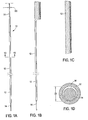
- FIGs. 1A-1D there is shown an endoluminal device and delivery system 10 comprising the endoluminal device 12 and a guidewire 14.
- Device 12 comprises a tubular member having a straightened configuration (shown in Fig. 1A mounted on guidewire 14) and a shape memory configuration (shown in Fig. 1C ) in the shape of a helical coil having a generally cylindrical envelope.
- the tubular member has a hollow core 34 with an interior diameter ID greater than the guidewire outer diameter OD by an amount sufficient to allow the tubular member to be placed on the guidewire in the straightened configuration.
- the tubular member is designed to assume the shape-memory configuration after the guidewire has been removed from the hollow core.
- the tubular member may comprise a hypotube.
- a hypotube is a hollow metal tube of very small diameter, of the type typically used in manufacturing hypo dermic needles (hence the name hyp otube).
- Members 32 may comprise any type of hollow tube, however, and are not limited only to tubes considered in the art to be hypotubes.
- the tubular member may comprise a plurality of filamentary members braided to simulate a hypotube (not shown), such as is known in the art with respect to manufacture of guidewires.
- tubular member as a stent has a number of advantages. First of all, because the tubular member may be advanced over a guidewire, rather than being held within a larger diameter sheath as is traditionally done in the art, the tubular member has an extremely low profile during deployment, which is advantageous for percutaneous methods of deployment. Another benefit of using a tubular member, is the capability of injecting or providing a drug into the tubular member before, during, or after deployment, as is described herein.
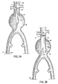
- endoluminal device 20 comprises not only tubular member 12a, which is mounted on guidewire 14a, but also a graft 21 attached at or near distal end D of the tubular member.
- Graft 21 may comprise any material known in the art for use in endoluminal devices, including but not limited to polyester, ePTFE (expanded PolyTetraFluoroEthylene), silk, and/or urethane. Graft 21 may be attached to the tubular member by an adhesive bond, a suture, or any other mechanism known in the art.
- graft 21 is a bifurcated graft comprising a trunk section 22, a first leg 23, and a second leg 24, and is adapted for repair of abdominal aortic aneurysms (AAA) 60.
- Grafts are not limited to bifurcated designs, however, and may have more than two legs or no legs. Likewise, bifurcated designs are not limited to AAA applications.
- Graft 21 may be a non-modular graft, or a modular graft such as shown in Figs. 2B-2D , in which trunk section 22, relatively longer first leg 23, and relatively shorter female portion 24a of second leg 24 comprise a first modular member, and male extended portion 24b of second leg 24 comprises a second modular member.
- a non-modular design may comprise a graft comprising a trunk section and two legs of equal size.
- One method of deploying device 20 comprises maneuvering first tubular member 12a over guidewire 14a (or maneuvering guidewire 14a through the lumen with the tubular member already mounted on the guidewire) until a desired deployment location is reached. Then, guidewire 14a is retracted, and/or first tubular member 12a is advanced past the distal end of the guidewire until the first tubular member is fully deployed, as shown in Fig. 2B .
- the first tubular member 12a may be advanced or using a pusher or stabilizer (not shown) mounted proximally of the tubular member, as such devices are known generally in the art.
- tubular member 12a has a high degree of "foreshortening" (a measure of the change in length between the shape memory configuration and the straightened configuration), such as is depicted for in the devices depicted in Figs. 1A-2C
- retraction of the guidewire and advancement of the pusher may be coordinated using a device similar to that shown and described in U.S. Patent 2003/191516, filed on April 4, 2002, by James Weldon and Ilya Yampolsky , assigned to the common assignee of this application.
- First tubular member 12a may have a construction similar to the design shown in Fig. 8 and described in derail below, in which a supply tube 82 is attached to its proximal end P of the tubular member and extends proximally therefrom, or member 12a may have no such supply tube.
- first tubular member 12a After first tubular member 12a has been deployed to secure a distal portion of truck section 22 of graft 21 against the body lumen, a second tubular member 12b may be deployed to secure a proximal portion of first leg 23, as shown in Fig. 2C .
- first tubular member 12a and second tubular member 12b may be mounted on a single guidewire 14a.
- second tubular member 12b may be positioned proximally of first tubular member 12a such that the second tubular member serves as a pusher for the first tubular member, as shown in Fig. 3 .
- the first tubular member may be mounted on a first guidewire and the second tubular member mounted on a second guidewire.
- the first and second guidewires may have features that enable rapid guidewire exchange as are known in the art, for example, such as are described in U.S. Patent No. 6,095,990, issued to Dr. Juan Parodi on August 1, 2000 .
- guidewire 14b may be advanced through the opposite iliac artery through which guidewire 14a was advanced.
- Tubular member 12c with attached graft 24b may then be advanced over guidewire 14b into a mating configuration with female portion 24a of leg 24.
- member 12c secures the distal end of male portion 24b to female portion 24a
- tubular member 12d secures the proximal end of portion 24b to the artery.
- tubular members 12c and 12d may be similarly configured on a single guidewire as shown in Fig. 3 , or on separate guidewires.
- members 12c and 12d may be end portions of a single tubular member that coils along the entire length of graft portion 24b, having a distal end portion 12c, a proximal end portion 12d, and a middle portion 12cd (shown in dashed lines).
- a single tubular member may comprise a helical pitch in portion 12cd that is larger than in portions 12c and 12d.
- members 12a and 12b may comprise a single tubular member, if desired.
- each member 32 comprising a hollow tube.
- each member 32 has its own guidewire 14, forming a plurality of parallel guidewires in the straightened configuration. Designs with multiple filaments may be held in a compressed configuration by a crocheted meshwork having a drawstring, such as is described in U.S. Patent No. 6,019,785 to Strecker .
- one or more of the hollow members may contain a substance therein.
- the hollow members that are advanced over guidewires may also contain the substance which is true with respect to multiple member embodiments such as is shown in Figs. 4A and 4B , and with respect to single member examples such as is shown in Figs. 1A-D , for example.
- tubular members 32 may comprise a plurality of openings 36, such as micro-machined or laser-drilled holes, for eluting the substance once the endoluminal device is placed in a body lumen, as shown in Fig. 5B .
- the eluted substance contained in the hollow tubes 32 may be any substance useful for delivering to the body lumen.
- the substance may comprise a biologically or pharmacologically active substance.
- the biologically or pharmacologically active substance may comprise a gelatinous suspension to prevent premature loss of the substance from the tubes until the device has been implanted in a body. Methods of making gelatinous carriers for biologically or pharmacologically active ingredients are well known in the art.
- biologically or pharmacologically active substance refers to,any substance, whether synthetic or natural, that has a pharmacological, chemical, or biological effect on the body or a portion thereof.
- Suitable biologically or pharmacologically active materials include without limitation glucocorticoids (e.g.
- dexamethasone, betamethasone), antithrombotic agents such as heparin, cell growth inhibitors, hirudin, angiopeptin, aspirin, growth factors such as VEGF, antisense agents, anti-cancer agents, anti-proliferative agents, oligonucleotides, antibiotics, and, more generally, antiplatelet agents, anti-coagulant agents, antimitotic agents, antioxidants, antimetabolite agents, and anti-inflammatory agents may be used.
- Antiplatelet agents can include drugs such as aspirin and dipyridamole. Aspirin is classified as an analgesic, antipyretic, anti-inflammatory and antiplatelet drug. Dipyridamole is a drug similar to aspirin in that it has anti-platelet characteristics.
- Anticoagulant agents may include drugs such as heparin, protamine, hirudin and tick anticoagulant protein.
- Anti-cancer agents may include drugs such as taxol and its analogs or derivatives. Taxol is als classified as a cell-growth inhibitor.
- Antioxidant agents may include probucol.
- Anti-proliferative agents may include drugs such as amlodipine and doxazosin.
- Antimitotic agents and antimetabolite agents may include drugs such as methotrexate, azathioprine, vincristine, vinblastine, 5-fluorouracil, adriamycin and mutamycin.
- Antibiotic agents can include penicillin, cefoxitin, oxacillin, tobramycin, and gentamicin. Suitable antioxidants include probucol. Also, genes or nucleic acids, or portions thereof may be used. Such genes or nucleic acids can first be packaged in liposomes or nanoparticles. Furthermore, collagen-synthesis inhibitors, such as tranilast, may be used.
- the active substance inside the tubular member may be the same as in the outer coating, or different, and the release characteristics of the substance inside the tubular member may be the same as the release characteristics of the outer coating, or different. For example, it may be desired to have a first substance in the outer coating that is released more quickly than a second substance inside the tubular member.
- a perforated tube 70 comprises an outer coating 72.
- This outer coating may be a coating impregnated with a biologically or pharmacologically active substance, such as described above, for use in tandem with a biologically or pharmacologically active substance 74 inside the perforated tube, it may be a layer that controls the release of substance 74, or both.
- coating 72 may comprise a substance such as but not limited to silicone or corethane, which allows substance 74 to leach through the coating material over time to provide a more controlled release of the substance. The coating controls the effusion of the substance out of the tube and may prevent effusion prior to implantation of the device in the body.
- Suitable materials and methods for coating a medical device with materials to control release of biologically or pharmacologically active substances through the coating are listed in U.S. Patent No. 6,096,070 .
- the '070 patent lists polymers including but not limited to polyamide, polymers of parylene or derivatives thereof, poly(ethylene oxide), poly(ethylene glycol), poly(propylene oxide), silicone based polymers, polymers of methane, tetrafluoroethylene or tetramethyldisiloxane and polymers derived from photopolymerizeable monomers.
- embodiments of the present invention may utilize any of the materials so listed.
- Exemplary stent 30 shown in Fig. 4A has a hexagonal cell architecture comprising a plurality of cells 40 defined by a plurality of members 32a, 32b, 32c, etc. positioned adjacent one another with parallel portions 42, divergent portions 44, and convergent portions 46 for each pair of adjacent members.
- the adjacent members may be attached to one another at one or more of the parallel portions 42, such as by an adhesive bond 43, a suture, a soldered joint, a braised joint, a weld, such as a laser weld, or any type of affixation made by any method known in the art.
- the type of affixation may be dependent upon the type of member.
- a hollow member designed for advancing over a guidewire or for containing a substance may be more preferably attached to adjacent members by an adhesive bond or other non-destructive technique rather than, for example, a weld, to assure that the affixation technique does not compromise the ability of the hollow member to adequately slide over the guidewire or for the substance to fill the entire length of the tube when injected from one end, if desired.
- stent polygonal cell stent architectures are also well-suited for use with multiple hollow tubes advanced over multiple guidewires.
- diamond shaped polygonal cells 47 as shown in the architecture of stent 45 as shown in Fig. 7 comprise a plurality of apices 48 abutting one another, with at least some of the apices are attached to one another, such as with a suture 48. Any attachment method known in the art may be used however, subject to the considerations discussed above with respect to the hexagonal cell architecture.
- the endoluminal device is not limited to any particular geometry or architecture, and may comprise any suitable pattern of one or more hypotubes.
- an extension 82 may extend to a location 80 outside of body lumen 81 or at least readily accessible from outside the body lumen.
- Extension 82 may be used as a tether and/or may be used as a supply tube for injecting a substance into the hollow core of device 86 to be eluted through openings 88 (or through a coating over the openings, as shown in and described with respect to Fig. 6 ).
- extension 82 may be remotely detachable by providing a predetermined disconnecting segment 84 at the interface between the supply tube and the device 86.
- disconnecting segment 84 may include a mechanically weaker circumferential portion of the hypotube that is meant to break at a lesser force than is needed to dislocate the stent from its implanted position.
- disconnecting segment 84 may comprise material that electrolytically corrodes preferentially relative to the hypotube material when energized with an electrical current.
- Segment 84 may also comprise a material this is dissolvable or weakened by a medically acceptable substance that can be injected through extension 82 to render the segment detachable. If a renewable supply of the substance to be eluted from the medical implant is desired over some period of time, the medical implant may have an extension that is left protruding from the body for some period of time to be used as a supply tube. The use of tubes protruding from the body for a period of time for use in supplying medicine to an internal location is well known in the art. When the connection is no longer desired, extension 82 is then severed from device 86 at disconnecting segment 84 by applying mechanical force, electrical current, or both.
- a tubular member 90 may not have any openings, such that the tubular member can permanently contain the substance even after the device is deployed.
- the member may comprise a plug 92 at one or both ends of the member, such as a silicone plug with a self-sealing slit 94 that contains the substance 96 but allows the member to slide on the guidewire. When guidewire 14 is pulled through slit 94, the slit seals itself.
- the substance may comprise a two-part resin 101 such as are known in the art of aneurysm occlusion.
- member 100 may be partially filled with a first part 102 of two-part resin 101 during delivery to the body, and the second part 104 injected after the member has been delivered into the deployment location.
- member 100 may be advanced over a hollow-core guidewire 106, such as are known in the art, and the second part 104 of two-part resin 101 may be delivered via the guidewire before it is completely retracted from inside of the member.
- the second part 104 may be injected as the member 100 is advanced off the end of guidewire 106, forming the combined resin 101 in the void created by the absence of the guidewire.
- member 110 may be hollow with a sealed distal end 112 comprising substance 114, such as for example, a contrast agent to make the stent more visible by imaging techniques. Because of the sealed end 112, member 110 and guidewire 116 may be advanced together into the body lumen until the end 112 reaches a desired destination point, and then guidewire 116 may be removed so that the member can deploy, for example, into a configuration similar to that as shown in Fig. 1C .
- End 112 may be sealed with a plug 113, such as a plug of silicone, and a similar plug may be provided at the proximal end of the chamber 115 containing substance 114, or the substance may comprise a resin that is self-sealing, such as a 2-part resin as described above.
- a plug 113 such as a plug of silicone
- a similar plug may be provided at the proximal end of the chamber 115 containing substance 114, or the substance may comprise a resin that is self-sealing, such as a 2-part resin as described above.
- Exemplary types of substances for use in sealed tubular members may include radioactive substances for providing localized radiation treatment, or a contrast agent as described above.
- the substance may also comprise a material that changes in viscosity or state after implantation into the body.
- change in viscosity or state it is meant that the material undergoes a change that affects the rigidity of the combination of the hypotube and substance contained therein. While in one embodiment the change in state may comprise a change from a liquid to a solid, it may also include a change from a first viscosity to a second viscosity sufficient to affect the rigidity of the combined hypotube with the substance inside.
- the desired result is to provide a stent that is more rigid after implantation, so the desired change in state is from a lesser viscosity to a greater viscosity.
- the change in state is not limited to any particular direction of change, however, and may go in the opposite direction if such a result is desired.
- the substance may comprise an adhesive such as a cyanoacrylate or polyethylene glycol that hardens when exposed to liquid.
- the liquid may be provided by a hollow guidewire in a similar manner as the second part of the 2-part resin is supplied as described above, or the liquid flowing in the body lumen may merely seep into the tubular member through open ends of the member, or through holes in the tubular member that are designed to let body liquid in rather than to let the substance in the member out.
- the substance may harden over time after exposure to the internal temperature of the body into which it is implanted, but remains fluid at lower or higher temperatures.
- the device must merely be kept at a higher or lower temperature until implantation in the body to prevent premature curing.
- the hypotube may be completely filled with the substance or partially filled, and the extent to which the hypotube is filled may take into consideration any expansion or contraction in volume of the substance upon the change in state or viscosity.
- stents which may be covered with graft material or uncovered, but may include other endoluminal devices such as occlusion devices, valves, coils, and filters, such as vena cava filters.
- a filter for example, may comprise a helical coil having a generally conical envelope 120, such as shown in Fig. 12 .
- a helical pitch for a filter is sufficiently wide to let blood flow through but sufficiently narrow to catch any loose thrombus, and having a hook 122 for ease of recapture.
- Occlusion devices such as device 130 shown in Fig.
- occlusion coils are also sometimes referred to as “occlusion coils,” “embolic coils,” or “wire clusters,” and may be used, for example, to close off a portion of a lumen, such as when deploying a uni-aorto-iliac device, as is known in the art.
- Such devices may also comprise helical coils having a generally conical envelope, but having a pitch so narrow that emboli form to occlude blood flow through the device.
- Endoluminal devices such as stents having attached grafts may be in the form of single lumen devices, or multi-lumen, branched devices, such as bifurcated devices for repair of abdominal aortic aneurysms (AAA).
- AAA abdominal aortic aneurysms
- the filamentary members described herein may comprise any suitable material known in the art for medical implantation, such as but not limited to nickel-titanium alloys, cobalt-chromium alloys such as elgiloy, stainless steel, and titanium.
- nickel-titanium alloys cobalt-chromium alloys such as elgiloy, stainless steel, and titanium.
- nitinol is preferred.
- the shape-memory tubular members it may be preferable for the A f Temperature (the temperature at which the shape memory alloy finishes transforming to Austenite upon heating) to be slightly greater than standard body temperature, to reduce friction and deflection of the guidewire during deployment of the device.
- the tubular member may be transformed to the shape memory configuration by using a warm flush of saline, such as injected via a hollow-core guidewire.
- multi-filament stents may comprise some mix of tubular members and non-tubular members, and the tubular members may comprise some mix of guidewire-advancing and non-guidewire-advancing members, the tubular members may also comprise some mix of members filled and unfilled with one or more substances. Different members may be filled with different substances. Some may not be filled at all.
- an exemplary device may comprise at least one portion comprising a hypotube with one or more openings adapted to elute a first substance contained therein and one portion comprising a hypotube without openings and adapted to permanently contain a second substance therein.
- a single implant may have both the ability to deliver a substance to the body and undergo a change in state upon implantation in the body, provide radioactive therapy, or provide enhanced imaging.
- one method comprises providing a delivery system comprising a guidewire having an outer diameter, and a self-expanding endoluminal device comprising at least one tubular filamentary member, in which the tubular filamentary member has a straightened configuration for mounting on the guidewire and a shape memory configuration for deployment in the body lumen, as shown in Figs. 1A-1D .
- a delivery system comprising a guidewire having an outer diameter
- a self-expanding endoluminal device comprising at least one tubular filamentary member, in which the tubular filamentary member has a straightened configuration for mounting on the guidewire and a shape memory configuration for deployment in the body lumen, as shown in Figs. 1A-1D .
- the guidewire is advanced into the body lumen to a deployment location, and the guidewire is used for deploying the tubular filamentary member in its shape-memory configuration into the deployment location.
- the guidewire may be advanced with the tubular filamentary member mounted on it, such that the deployment step comprises retracting the guidewire and/or advancing the tubular filamentary member off of a distal end of the guidewire into the deployment location.
- the guidewire may be advanced without the tubular filamentary member mounted on it, in which the deployment step comprises advancing the tubular filamentary member over the guidewire and off of a distal end of the guidewire into the deployment location.
- the method may also comprise injecting a substance into the tubular filamentary member.
- this method further comprises the tubular filamentary member eluting the substance into the body lumen, such as embodiments in which the substance is a biologically or pharmacologically active substance such as but not limited to those discussed above.
- the method comprises injecting the substance into the tubular filamentary member through the proximal extension.
- the method may further comprise severing the proximal extension from the tubular filamentary member at the severable connecting element.
- the severing step may comprise applying a mechanical force and/or applying an electric current originating at or near the proximal end of the proximal extension, or injecting a solvent into the proximal extension to dissolve the severable connecting element.
Claims (48)
- Selbstexpandierende endoluminale Vorrichtung (30), umfassend mindestens ein röhrenförmiges Fadenelement (32), das einen Hohlkern (34) zum Aufnehmen eines Führungsdrahts (14) aufweist, wobei das röhrenförmige Fadenelement (32) eine gerichtete Ausgestaltung aufweist, bei der sich der Führungsdraht (14) in dem Hohlkern (34) befindet, und eine Formgedächtnis-Ausgestaltung, bei der sich der Führungsdraht (14) nicht in dem Hohlkern (34) befindet, wobei die selbstexpandierende endoluminale Vorrichtung eine Mehrzahl röhrenförmiger Fadenelemente (32) umfasst, die aneinander befestigt sind, dadurch gekennzeichnet, dass jedes röhrenförmige Fadenelement (32) ausgestaltet ist, einen Führungsdraht (14) aufzunehmen, und die Mehrzahl röhrenförmiger Fadenelemente (32) somit ausgestaltet ist, eine Mehrzahl paralleler Führungsdrähte in der gerichteten Ausgestaltung aufzunehmen.
- Endoluminale Vorrichtung (30) nach Anspruch 1, überdies umfassend eine Substanz (74) innerhalb des Hohlkerns (34) des röhrenförmigen Fadenelements.
- Endoluminale Vorrichtung (30) nach Anspruch 2, wobei der Hohlkern (34) des röhrenförmigen Fadenelements angepasst ist, die Substanz (74) permanent zu enthalten.
- Endoluminale Vorrichtung (30) nach Anspruch 2, wobei das röhrenförmige Fadenelement eine oder mehrere Öffnung/en (36) umfasst, durch die die Substanz (74) aus dem Hohlkern (34) herausgespült werden kann.
- Endoluminale Vorrichtung (30) nach Anspruch 4, wobei das röhrenförmige Fadenelement (32) mit einem Beschichtungsmaterial (72) beschichtet ist, wobei das Beschichtungsmaterial (a) ein Material umfasst, durch das die Substanz innerhalb des Hohlkerns (34) des röhrenförmigen Fadenelements hindurchsickern kann, (b) ein Material umfasst, das die mindestens eine biologisch oder pharmakologisch aktive Substanz (74) umfasst oder (c) sowohl (a) als auch (b) umfasst.
- Endoluminale Vorrichtung (30) nach Anspruch 1, überdies umfassend eine proximale Verlängerung des röhrenförmigen Fadenelements (32), die sich zu einem proximalen Ende außerhalb des Körperlumens erstreckt.
- Endoluminale Vorrichtung (30) nach Anspruch 6, überdies umfassend ein trennbares Verbindungselement zwischen der proximalen Verlängerung und der endoluminalen Vorrichtung.
- Endoluminale Vorrichtung (30) nach Anspruch 1, wobei die endoluminale Vorrichtung überdies ein oder mehrere nicht röhrenförmige Fadenelement/e umfasst.
- Endoluminale Vorrichtung (30) nach Anspruch 1, wobei die Vorrichtung eine Af-Temperatur aufweist, die größer ist als eine innere Standardtemperatur eines Lumens, in das sie zu entfalten ist.
- Endoluminale Vorrichtung (30) und Einbringungssystem zum Entfalten der endoluminalen Vorrichtung in einem Körperlumen von einer proximalen Stelle außerhalb des Körperlumens, wobei die endoluminale Vorrichtung und das Einbringungssystem umfassen:mindestens einen Führungsdraht; unddie selbstexpandierende endoluminale Vorrichtung (30) nach Anspruch 1.
- Endoluminale Vorrichtung (30) und Einbringungssystem nach Anspruch 10, überdies umfassend eine Substanz, die innerhalb des Hohlkems (34) des röhrenförmigen Fadenelements enthalten ist.
- Endoluminale Vorrichtung (30) und Einbringungssystem nach Anspruch 11, wobei das röhrenförmige Fadenelement (32) angepasst ist, die Substanz (74) permanent in dem Hohlkern (34) zu enthalten.
- Endoluminale Vorrichtung (30) und Einbringungssystem nach Anspruch 12, wobei das röhrenförmige Fadenelement (32) einen Stopfen an einem oder mehreren Ende/n des röhrenförmigen Elements zum Enthalten der Substanz (74) umfasst.
- Endoluminale Vorrichtung (30) und Einbringungssystem nach Anspruch 13, wobei der Stopfen ein selbstdichtendes Material umfasst, das einen Schlitz darin zum Unterbringen des Führungsdrahts (14) aufweist.
- Endoluminale Vorrichtung (30) und Einbringungssystem nach Anspruch 12, wobei die Substanz einen Zwei-Komponenten-Harz umfasst, der in situ kombiniert wird.
- Endoluminale Vorrichtung (30) und Einbringungssystem nach Anspruch 11, wobei das röhrenförmige Fadenelement nur teilweise mit der Substanz gefüllt ist.
- Endoluminale Vorrichtung (30) und Einbringungssystem nach Anspruch 16, wobei die Vorrichtung ein distales Ende umfasst, das die darin abgedichtete Substanz aufweist.
- Endoluminale Vorrichtung (30) und Einbringungssystem nach Anspruch 12, wobei die Substanz (74) angepasst ist, eine Veränderung der Viskosität oder des Zustands durchzumachen, nachdem die Vorrichtung in einer Entfaltungsstelle implantiert worden ist.
- Endoluminale Vorrichtung (30) und Einbringungssystem nach Anspruch 11, wobei die Substanz (74) eine radioaktive Substanz umfasst.
- Endoluminale Vorrichtung (30) und Einbringungssystem nach Anspruch 11, wobei die Substanz (74) ein Kontrastmittel umfasst.
- Endoluminale Vorrichtung (30) und Einbringungssystem nach Anspruch 11, wobei das röhrenförmige Fadenelement (32) eine oder mehrere Öffnung/en (36) umfasst, die angepasst ist/sind, um das Herausspülen der Substanz (74) aus dem Hohlkern (34) zu erlauben.
- Endoluminale Vorrichtung (30) und Einbringungssystem nach Anspruch 21, wobei die Substanz (74) mindestens eine biologisch oder pharmakologisch aktive Substanz umfasst.
- Endoluminale Vorrichtung (30) und Einbringungssystem nach Anspruch 22, wobei die mindestens eine biologisch oder pharmakologisch aktive Substanz (74) einen oder mehrere aktive Bestandteile umfasst, der/die aus der Gruppe ausgewählt ist/sind, bestehend aus: Glucocorticoiden; antithrombotischen Mitteln, Zellwachstums-Inhibitoren; Hirudin, Angiopeptin; Aspirin; Wachstumsfaktoren; Antisense-Mitteln; Antikrebsmitteln; antiproliferativen Mitteln; Oligonucleotiden; Antibiotika; antithrombozytären Mitteln; antikoagulierenden Mitteln; antimitotischen Mitteln; Antioxidantien; antimetabolitischen Mitteln, entzündungshemmenden Mitteln; Genen; Nukleinsäuren oder Teilen davon; schmerzlindernden Mitteln; fiebersenkenden Mitteln; blutgefäßerweiternden Mitteln; und Kollagen-Synthese-Inhibitoren.
- Endoluminale Vorrichtung (30) und Einbringungssystem nach Anspruch 22, wobei das röhrenförmige Fadenelement (32) mit einem Beschichtungsmaterial (72) beschichtet ist, wobei das Beschichtungsmaterial (a) ein Material umfasst, durch das die mindestens eine biologisch oder pharmakologisch aktive Substanz (74) hindurchsickem kann, (b) ein Material umfasst, das die mindestens eine oder mindestens eine andere biologisch oder pharmakologisch aktive Substanz (74) umfasst oder (c) sowohl (a) als auch (b) umfasst.
- Endoluminale Vorrichtung (30) und Einbringungssystem nach Anspruch 24, wobei das Beschichtungsmaterial ein Material umfasst, das aus der Gruppe ausgewählt ist, bestehend aus: Silikon; Corethan; Polyamid; Polymeren von Parylen oder Derivaten davon; Polyethylenoxid; Polyethylenglykol; Polypropylenoxid; silikonbasierten Polymeren; Polymeren von Methan; Tetrafluoroethylen; Tetramethyldisiloxan; und von photopolymerisierbaren Monomeren stämmigen Polymeren.
- Endoluminale Vorrichtung (30) und Einbringungssystem nach Anspruch 22, wobei die Substanz (74) eine gelatineartige Suspension umfasst.
- Endoluminale Vorrichtung (30) und Einbringungssystem nach Anspruch 21, wobei die Öffnungen (36) feinbearbeitete oder lasergebohrte Löcher umfassen.
- Endoluminale Vorrichtung (30) und Einbringungssystem nach Anspruch 10, wobei das röhrenförmige Fadenelement (32) ein Hyporohr umfasst.
- Endoluminale Vorrichtung (30) und Einbringungssystem nach Anspruch 10, wobei die endoluminale Vorrichtung eine Vorrichtung umfasst, die aus der Gruppe ausgewählt ist, bestehend aus: einem Stent; einem Filter oder einer Okklusionsvorrichtung.
- Endoluminale Vorrichtung (30) und Einbringungssystem nach Anspruch 10, wobei die endoluminale Vorrichtung eine allgemein zylindrische Ummantelung in der Formgedächtnis-Ausgestaltung umfasst.
- Endoluminale Vorrichtung (30) und Einbringungssystem nach Anspruch 10, wobei das röhrenförmige Fadenelement (32) eine Nickel-Titan-Legierung umfasst.
- Endoluminale Vorrichtung (30) und Einbringungssystem nach Anspruch 10, überdies umfassend eine proximale Verlängerung des röhrenförmigen Fadenelements (32), das sich zu einem proximalen Ende außerhalb des Körperlumens erstreckt.
- Endoluminale Vorrichtung (30) und Einbringungssystem nach Anspruch 32, überdies umfassend ein trennbares Verbindungselement zwischen der proximalen Verlängerung und der endoluminalen Vorrichtung.
- Endoluminale Vorrichtung (30) und Einbringungssystem nach Anspruch 33, wobei das Verbindungselement durch Anwenden einer mechanischen Kraft trennbar ist, die von dem oder nahe dem proximalen Ende der proximalen Verlängerung herrührt.
- Endoluminale Vorrichtung (30) und Einbringungssystem nach Anspruch 32, wobei das Verbindungselement durch Anlegen eines elektrischen Stroms trennbar ist, der von dem oder nahe dem proximalen Ende der proximalen Verlängerung herrührt.
- Endoluminale Vorrichtung (30) und Einbringungssystem nach Anspruch 33, wobei das Verbindungselement durch Auflösen mittels Injektion eines Lösungsmittels in das röhrenförmige Fadenelement (32) trennbar ist.
- Endoluminale Vorrichtung (30) und Einbringungssystem nach Anspruch 10, wobei die Vorrichtung überdies ein oder mehrere nicht-röhrenförmige Fadenelement/e umfasst.
- Endoluminale Vorrichtung (30) und Einbringungssystem nach Anspruch 10, überdies umfassend eine Mehrzahl paralleler Führungsdrähte (14), wobei jeder Führungsdraht (14) zum Eingreifen in eines der Mehrzahl röhrenförmiger Fadenelemente (32) dient.
- Endoluminale Vorrichtung (30) und Einbringungssystem nach Anspruch 10, wobei mindestens eines der röhrenförmigen Fadenelemente (32) mindestens teilweise eine Substanz (74) enthält.
- Endoluminale Vorrichtung (30) und Einbringungssystem nach Anspruch 10, wobei das mindestens eine röhrenförmige Fadenelement (32) angepasst ist, die Substanz (74) herauszuspülen.
- Endoluminale Vorrichtung (30) und Einbringungssystem nach Anspruch 39, wobei das mindestens eine röhrenförmige Fadenelement (32) angepasst ist, die Substanz (74) permanent zu enthalten.
- Endoluminale Vorrichtung (30) und Einbringungssystem nach Anspruch 39, wobei das mindestens eine röhrenförmige Fadenelement (32), das zumindest teilweise die Substanz (74) enthält, ebenfalls angepasst ist, über einen Führungsdraht (14) vorgeschoben zu werden.
- Endoluminale Vorrichtung (30) und Einbringungssystem nach Anspruch 39, wobei das mindestens eine röhrenförmige Fadenelement (32), das zumindest teilweise die Substanz (74) enthält, nicht ebenfalls angepasst ist, über einen Führungsdraht (14) vorgeschoben zu werden.
- Endoluminale Vorrichtung (30) und Einbringungssystem nach Anspruch 10, wobei die endoluminale Vorrichtung eine Mehrzahl polygonaler Zellen umfasst.
- Endoluminale Vorrichtung (30) und Einbringungssystem nach Anspruch 10, wobei die polygonalen Zellen hexagonal sind.
- Endoluminale Vorrichtung (30) und Einbringungssystem nach Anspruch 10, wobei die polygonalen Zellen diamantenförmig sind.
- Endoluminale Vorrichtung (30) nach Anspruch 10, wobei der Führungsdraht (14) einen Hohlkern umfasst.
- Endoluminale Vorrichtung (30) und Einbringungssystem nach Anspruch 10, überdies umfassend eine Substanz zum Injizieren innerhalb des Hohlkems (34) des Fadenelements und Mittel zum Injizieren der Substanz (74) in den Hohlkern (34) des Fadenelements.
Applications Claiming Priority (3)
| Application Number | Priority Date | Filing Date | Title |
|---|---|---|---|
| US139127 | 2002-05-03 | ||
| US10/139,127 US7122048B2 (en) | 2002-05-03 | 2002-05-03 | Hypotube endoluminal device |
| PCT/US2003/010332 WO2003092547A1 (en) | 2002-05-03 | 2003-04-03 | Hypotube endoluminal device |
Publications (2)
| Publication Number | Publication Date |
|---|---|
| EP1503699A1 EP1503699A1 (de) | 2005-02-09 |
| EP1503699B1 true EP1503699B1 (de) | 2010-05-19 |
Family
ID=29269515
Family Applications (1)
| Application Number | Title | Priority Date | Filing Date |
|---|---|---|---|
| EP03719582A Expired - Lifetime EP1503699B1 (de) | 2002-05-03 | 2003-04-03 | Endoluminale hyporohrvorrichtung |
Country Status (6)
| Country | Link |
|---|---|
| US (3) | US7122048B2 (de) |
| EP (1) | EP1503699B1 (de) |
| AT (1) | ATE468088T1 (de) |
| AU (1) | AU2003223452A1 (de) |
| DE (1) | DE60332615D1 (de) |
| WO (1) | WO2003092547A1 (de) |
Families Citing this family (112)
| Publication number | Priority date | Publication date | Assignee | Title |
|---|---|---|---|---|
| US6951572B1 (en) * | 1997-02-20 | 2005-10-04 | Endologix, Inc. | Bifurcated vascular graft and method and apparatus for deploying same |
| US7713297B2 (en) | 1998-04-11 | 2010-05-11 | Boston Scientific Scimed, Inc. | Drug-releasing stent with ceramic-containing layer |
| US6261316B1 (en) | 1999-03-11 | 2001-07-17 | Endologix, Inc. | Single puncture bifurcation graft deployment system |
| US8034100B2 (en) * | 1999-03-11 | 2011-10-11 | Endologix, Inc. | Graft deployment system |
| EP1333787B1 (de) * | 2000-11-15 | 2009-12-23 | Endologix, Inc. | Implantierbare gefässprothese |
| US20040087886A1 (en) * | 2002-10-30 | 2004-05-06 | Scimed Life Systems, Inc. | Linearly expandable ureteral stent |
| KR20050091040A (ko) * | 2002-12-30 | 2005-09-14 | 안지오테크 인터내셔날 아게 | 실크 함유 스텐트 이식편 |
| US20040260384A1 (en) * | 2003-06-17 | 2004-12-23 | Medtronic Ave | Superelastic coiled stent |
| US20050080448A1 (en) * | 2003-09-18 | 2005-04-14 | Kear Jason W. | Medical retrieval devices and related methods of use |
| US20050096725A1 (en) | 2003-10-29 | 2005-05-05 | Pomeranz Mark L. | Expandable stent having removable slat members |
| US8267985B2 (en) | 2005-05-25 | 2012-09-18 | Tyco Healthcare Group Lp | System and method for delivering and deploying an occluding device within a vessel |
| US20060025802A1 (en) * | 2004-07-30 | 2006-02-02 | Sowers William W | Embolic coil delivery system with U-shaped fiber release mechanism |
| US7918872B2 (en) | 2004-07-30 | 2011-04-05 | Codman & Shurtleff, Inc. | Embolic device delivery system with retractable partially coiled-fiber release |
| US20060025801A1 (en) * | 2004-07-30 | 2006-02-02 | Robert Lulo | Embolic device deployment system with filament release |
| US7695506B2 (en) * | 2004-09-21 | 2010-04-13 | Boston Scientific Scimed, Inc. | Atraumatic connections for multi-component stents |
| US8845676B2 (en) | 2004-09-22 | 2014-09-30 | Micro Therapeutics | Micro-spiral implantation device |
| WO2006032289A1 (de) | 2004-09-22 | 2006-03-30 | Dendron Gmbh | Medizinisches implantat |
| US7147659B2 (en) * | 2004-10-28 | 2006-12-12 | Cordis Neurovascular, Inc. | Expandable stent having a dissolvable portion |
| US7156871B2 (en) * | 2004-10-28 | 2007-01-02 | Cordis Neurovascular, Inc. | Expandable stent having a stabilized portion |
| ES2764992T3 (es) | 2005-04-04 | 2020-06-05 | Flexible Stenting Solutions Inc | Stent flexible |
| JP5312018B2 (ja) * | 2005-04-05 | 2013-10-09 | エリクシアー メディカル コーポレイション | 分解性の移植可能な医療装置 |
| US8273101B2 (en) * | 2005-05-25 | 2012-09-25 | Tyco Healthcare Group Lp | System and method for delivering and deploying an occluding device within a vessel |
| AU2005332044B2 (en) * | 2005-05-25 | 2012-01-19 | Covidien Lp | System and method for delivering and deploying and occluding device within a vessel |
| US20070073334A1 (en) * | 2005-09-29 | 2007-03-29 | Kamal Ramzipoor | Combined electrolytic and mechanical separation background |
| US20080114435A1 (en) * | 2006-03-07 | 2008-05-15 | Med Institute, Inc. | Flexible delivery system |
| US20070224235A1 (en) | 2006-03-24 | 2007-09-27 | Barron Tenney | Medical devices having nanoporous coatings for controlled therapeutic agent delivery |
| US8187620B2 (en) | 2006-03-27 | 2012-05-29 | Boston Scientific Scimed, Inc. | Medical devices comprising a porous metal oxide or metal material and a polymer coating for delivering therapeutic agents |
| US8864790B2 (en) | 2006-04-17 | 2014-10-21 | Covidien Lp | System and method for mechanically positioning intravascular implants |
| US8815275B2 (en) | 2006-06-28 | 2014-08-26 | Boston Scientific Scimed, Inc. | Coatings for medical devices comprising a therapeutic agent and a metallic material |
| JP2009542359A (ja) | 2006-06-29 | 2009-12-03 | ボストン サイエンティフィック リミテッド | 選択的被覆部を備えた医療装置 |
| US9265865B2 (en) * | 2006-06-30 | 2016-02-23 | Boston Scientific Scimed, Inc. | Stent having time-release indicator |
| US9173733B1 (en) | 2006-08-21 | 2015-11-03 | Abbott Cardiovascular Systems Inc. | Tracheobronchial implantable medical device and methods of use |
| JP2010503469A (ja) | 2006-09-14 | 2010-02-04 | ボストン サイエンティフィック リミテッド | 薬物溶出性皮膜を有する医療デバイス |
| US20080071343A1 (en) * | 2006-09-15 | 2008-03-20 | Kevin John Mayberry | Multi-segmented graft deployment system |
| US7981150B2 (en) | 2006-11-09 | 2011-07-19 | Boston Scientific Scimed, Inc. | Endoprosthesis with coatings |
| US8523931B2 (en) * | 2007-01-12 | 2013-09-03 | Endologix, Inc. | Dual concentric guidewire and methods of bifurcated graft deployment |
| US20080288045A1 (en) * | 2007-02-22 | 2008-11-20 | Mohsin Saeed | Apparatus and method for implantation of a bifurcated endovascular prosthesis |
| US8821567B2 (en) | 2007-02-22 | 2014-09-02 | Mohsin Saeed | Apparatus and method for implantation of a bifurcated endovascular prosthesis |
| US8431149B2 (en) | 2007-03-01 | 2013-04-30 | Boston Scientific Scimed, Inc. | Coated medical devices for abluminal drug delivery |
| US8070797B2 (en) | 2007-03-01 | 2011-12-06 | Boston Scientific Scimed, Inc. | Medical device with a porous surface for delivery of a therapeutic agent |
| JP5249249B2 (ja) | 2007-03-13 | 2013-07-31 | コヴィディエン リミテッド パートナーシップ | コイルと耐伸張性部材とが含まれているインプラント |
| US8067054B2 (en) | 2007-04-05 | 2011-11-29 | Boston Scientific Scimed, Inc. | Stents with ceramic drug reservoir layer and methods of making and using the same |
| JP2010523260A (ja) * | 2007-04-12 | 2010-07-15 | ボストン サイエンティフィック リミテッド | 血管閉塞装置のための瞬時機械的脱着機構 |
| US7976915B2 (en) | 2007-05-23 | 2011-07-12 | Boston Scientific Scimed, Inc. | Endoprosthesis with select ceramic morphology |
| US8435283B2 (en) * | 2007-06-13 | 2013-05-07 | Boston Scientific Scimed, Inc. | Anti-migration features and geometry for a shape memory polymer stent |
| US7942926B2 (en) | 2007-07-11 | 2011-05-17 | Boston Scientific Scimed, Inc. | Endoprosthesis coating |
| US8002823B2 (en) | 2007-07-11 | 2011-08-23 | Boston Scientific Scimed, Inc. | Endoprosthesis coating |
| JP2010533563A (ja) | 2007-07-19 | 2010-10-28 | ボストン サイエンティフィック リミテッド | 吸着抑制表面を有する内部人工器官 |
| US8815273B2 (en) | 2007-07-27 | 2014-08-26 | Boston Scientific Scimed, Inc. | Drug eluting medical devices having porous layers |
| US7931683B2 (en) | 2007-07-27 | 2011-04-26 | Boston Scientific Scimed, Inc. | Articles having ceramic coated surfaces |
| US8221822B2 (en) | 2007-07-31 | 2012-07-17 | Boston Scientific Scimed, Inc. | Medical device coating by laser cladding |
| US7988723B2 (en) | 2007-08-02 | 2011-08-02 | Flexible Stenting Solutions, Inc. | Flexible stent |
| EP2185103B1 (de) | 2007-08-03 | 2014-02-12 | Boston Scientific Scimed, Inc. | Überzug für ein medizinprodukt mit vergrösserter oberfläche |
| US8360995B2 (en) * | 2007-09-18 | 2013-01-29 | Cook Medical Technologies Llc | Wire guide |
| US20090093871A1 (en) * | 2007-10-08 | 2009-04-09 | Medtronic Vascular, Inc. | Medical Implant With Internal Drug Delivery System |
| US20090099591A1 (en) | 2007-10-15 | 2009-04-16 | Boston Scientific Scimed, Inc. | Coil Anchor Systems and Methods of Use |
| US9107741B2 (en) | 2007-11-01 | 2015-08-18 | Cook Medical Technologies Llc | Flexible stent graft |
| US8029554B2 (en) | 2007-11-02 | 2011-10-04 | Boston Scientific Scimed, Inc. | Stent with embedded material |
| US8216632B2 (en) | 2007-11-02 | 2012-07-10 | Boston Scientific Scimed, Inc. | Endoprosthesis coating |
| US7938855B2 (en) | 2007-11-02 | 2011-05-10 | Boston Scientific Scimed, Inc. | Deformable underlayer for stent |
| US8016880B2 (en) * | 2007-11-16 | 2011-09-13 | Medtronic Vascular, Inc. | Stent having spiral channel for drug delivery |
| BRPI0704464A2 (pt) * | 2007-11-30 | 2009-07-28 | Melchiades Da Cunha Neto | endoprótese, sistema de entrega da mesma no interior do vaso de um paciente e usos de dito sistema de entrega e de dita endoprótese |
| US8608792B2 (en) * | 2007-11-30 | 2013-12-17 | Scitech Produtos Medicos Ltda | Endoprosthesis and delivery system for delivering the endoprosthesis within a vessel of a patient |
| US20090163919A1 (en) * | 2007-12-19 | 2009-06-25 | Peter Tarcha | Devices, systems, and methods for delivery of a pharmaceutical to a subject's spine |
| US8221494B2 (en) | 2008-02-22 | 2012-07-17 | Endologix, Inc. | Apparatus and method of placement of a graft or graft system |
| US8236040B2 (en) | 2008-04-11 | 2012-08-07 | Endologix, Inc. | Bifurcated graft deployment systems and methods |
| US8920491B2 (en) | 2008-04-22 | 2014-12-30 | Boston Scientific Scimed, Inc. | Medical devices having a coating of inorganic material |
| WO2009132176A2 (en) | 2008-04-24 | 2009-10-29 | Boston Scientific Scimed, Inc. | Medical devices having inorganic particle layers |
| US9675482B2 (en) | 2008-05-13 | 2017-06-13 | Covidien Lp | Braid implant delivery systems |
| EP2303350A2 (de) | 2008-06-18 | 2011-04-06 | Boston Scientific Scimed, Inc. | Endoprothesen-beschichtung |
| JP5134729B2 (ja) | 2008-07-01 | 2013-01-30 | エンドロジックス、インク | カテーテルシステム |
| US9149376B2 (en) | 2008-10-06 | 2015-10-06 | Cordis Corporation | Reconstrainable stent delivery system |
| US9149377B2 (en) * | 2008-10-10 | 2015-10-06 | Veryan Medical Ltd. | Stent suitable for deployment in a blood vessel |
| US8231980B2 (en) | 2008-12-03 | 2012-07-31 | Boston Scientific Scimed, Inc. | Medical implants including iridium oxide |
| US20110282426A1 (en) * | 2009-01-23 | 2011-11-17 | Ashish Sudhir Mitra | Endovascular devices and associated systems and methods |
| US8071156B2 (en) | 2009-03-04 | 2011-12-06 | Boston Scientific Scimed, Inc. | Endoprostheses |
| US7942917B2 (en) * | 2009-04-17 | 2011-05-17 | Medtronic Vascular, Inc. | Hollow helical stent system |
| US8287937B2 (en) | 2009-04-24 | 2012-10-16 | Boston Scientific Scimed, Inc. | Endoprosthese |
| US8945202B2 (en) | 2009-04-28 | 2015-02-03 | Endologix, Inc. | Fenestrated prosthesis |
| EP2424447A2 (de) * | 2009-05-01 | 2012-03-07 | Endologix, Inc. | Perkutanes verfahren und vorrichtung zur behandlung von dissektionen |
| US10772717B2 (en) | 2009-05-01 | 2020-09-15 | Endologix, Inc. | Percutaneous method and device to treat dissections |
| US9283305B2 (en) | 2009-07-09 | 2016-03-15 | Medtronic Vascular, Inc. | Hollow tubular drug eluting medical devices |
| WO2011008989A2 (en) | 2009-07-15 | 2011-01-20 | Endologix, Inc. | Stent graft |
| WO2011017123A2 (en) | 2009-07-27 | 2011-02-10 | Endologix, Inc. | Stent graft |
| CN102470029B (zh) * | 2009-07-31 | 2015-06-17 | 乔泰克公司 | 一体式分叉移植物 |
| US20110070358A1 (en) | 2009-09-20 | 2011-03-24 | Medtronic Vascular, Inc. | Method of forming hollow tubular drug eluting medical devices |
| US8678046B2 (en) | 2009-09-20 | 2014-03-25 | Medtronic Vascular, Inc. | Apparatus and methods for loading a drug eluting medical device |
| US8828474B2 (en) | 2009-09-20 | 2014-09-09 | Medtronic Vascular, Inc. | Apparatus and methods for loading a drug eluting medical device |
| US8381774B2 (en) | 2009-09-20 | 2013-02-26 | Medtronic Vascular, Inc. | Methods for loading a drug eluting medical device |
| DE102009052002B4 (de) * | 2009-11-05 | 2012-09-27 | Acandis Gmbh & Co. Kg | Medizinische Vorrichtung zum Rekanalisieren von Körperhohlräumen und Set umfassend eine derartige Vorrichtung |
| US20110218617A1 (en) * | 2010-03-02 | 2011-09-08 | Endologix, Inc. | Endoluminal vascular prosthesis |
| US8333801B2 (en) | 2010-09-17 | 2012-12-18 | Medtronic Vascular, Inc. | Method of Forming a Drug-Eluting Medical Device |
| US8616040B2 (en) | 2010-09-17 | 2013-12-31 | Medtronic Vascular, Inc. | Method of forming a drug-eluting medical device |
| US8632846B2 (en) | 2010-09-17 | 2014-01-21 | Medtronic Vascular, Inc. | Apparatus and methods for loading a drug eluting medical device |
| JP6261339B2 (ja) | 2010-11-02 | 2018-01-17 | エンドロジックス、インク | グラフトまたはグラフトシステムの配置の器具および方法 |
| US9393100B2 (en) | 2010-11-17 | 2016-07-19 | Endologix, Inc. | Devices and methods to treat vascular dissections |
| US9155612B2 (en) * | 2011-01-10 | 2015-10-13 | Intermountain Invention Management, Llc | Composite stent grafts for in situ assembly and related methods |
| CN103561807B (zh) | 2011-03-01 | 2015-11-25 | 恩朵罗杰克斯股份有限公司 | 导管系统及其使用方法 |
| US9579104B2 (en) | 2011-11-30 | 2017-02-28 | Covidien Lp | Positioning and detaching implants |
| US9011480B2 (en) | 2012-01-20 | 2015-04-21 | Covidien Lp | Aneurysm treatment coils |
| US9687245B2 (en) | 2012-03-23 | 2017-06-27 | Covidien Lp | Occlusive devices and methods of use |
| US8998977B2 (en) * | 2012-04-13 | 2015-04-07 | Medtronic Vascular, Inc. | Hollow drug-filled stent and method of forming hollow drug-filled stent |
| US9155645B2 (en) | 2012-06-26 | 2015-10-13 | Abbott Cardiovascular Systems Inc. | Implantable prosthesis with radiopaque particles and method of making same |
| US9149375B2 (en) | 2012-06-26 | 2015-10-06 | Abbott Cardiovascular Systems Inc. | Radiopaque drug-filled prosthesis and method of making same |
| US9155647B2 (en) | 2012-07-18 | 2015-10-13 | Covidien Lp | Methods and apparatus for luminal stenting |
| EP2967938B1 (de) | 2013-03-14 | 2017-03-01 | Medtronic Vascular Inc. | Verfahren zur herstellung eines stents und dadurch hergestellter stent |
| US10300244B2 (en) * | 2013-07-22 | 2019-05-28 | Renalsense Ltd. | Unravelable catheter |
| CN103932751B (zh) * | 2014-01-23 | 2016-03-30 | 赵雨辰 | 一种体内填塞给药引流支架 |
| US9713475B2 (en) | 2014-04-18 | 2017-07-25 | Covidien Lp | Embolic medical devices |
| WO2017004265A1 (en) | 2015-06-30 | 2017-01-05 | Endologix, Inc. | Locking assembly for coupling guidewire to delivery system |
| WO2017015571A1 (en) | 2015-07-23 | 2017-01-26 | Novaflux, Inc. | Implants and constructs including hollow fibers |
| WO2018129455A1 (en) | 2017-01-09 | 2018-07-12 | Boston Scientific Scimed, Inc. | Guidewire with tactile feel |
Citations (1)
| Publication number | Priority date | Publication date | Assignee | Title |
|---|---|---|---|---|
| WO2003041615A1 (de) * | 2001-11-12 | 2003-05-22 | Dendron Gmbh | Medizinisches implantat |
Family Cites Families (49)
| Publication number | Priority date | Publication date | Assignee | Title |
|---|---|---|---|---|
| US4503569A (en) | 1983-03-03 | 1985-03-12 | Dotter Charles T | Transluminally placed expandable graft prosthesis |
| FR2576779B1 (fr) * | 1985-02-07 | 1988-10-07 | Tornier Sa | Dispositif d'assemblage entre un implant osseux et l'outil destine a sa mise en place |
| CH669107A5 (de) * | 1986-04-03 | 1989-02-28 | Sulzer Ag | Blattartiger schaft fuer die verankerung einer hueftgelenksprothese im femur. |
| SE459473B (sv) * | 1987-02-13 | 1989-07-10 | Stig Bengmark | Slanganordning, saerskilt foer administrering av naeringsmedel direkt i tarmen |
| US4919679A (en) * | 1989-01-31 | 1990-04-24 | Osteonics Corp. | Femoral stem surgical instrument system |
| DE69108423T2 (de) * | 1990-02-08 | 1995-07-27 | Howmedica | Aufblasbarer Dilatator. |
| DE4104702C2 (de) * | 1991-02-15 | 1996-01-18 | Malte Neuss | Implantate für Organwege in Wendelform |
| US5207644A (en) | 1991-03-04 | 1993-05-04 | Strecker Ernst P | Device with implantable infusion chamber and a catheter extending therefrom |
| US5064427A (en) * | 1991-05-14 | 1991-11-12 | Intermedics Orthopedics, Inc. | Apparatus for inserting and withdrawing humeral prosthesis |
| US5500013A (en) | 1991-10-04 | 1996-03-19 | Scimed Life Systems, Inc. | Biodegradable drug delivery vascular stent |
| US5256146A (en) * | 1991-10-11 | 1993-10-26 | W. D. Ensminger | Vascular catheterization system with catheter anchoring feature |
| US6059825A (en) | 1992-03-05 | 2000-05-09 | Angiodynamics, Inc. | Clot filter |
| US5413560A (en) | 1992-03-30 | 1995-05-09 | Pameda N.V. | Method of rapid catheter exchange |
| US5405378A (en) | 1992-05-20 | 1995-04-11 | Strecker; Ernst P. | Device with a prosthesis implantable in the body of a patient |
| DE4222380A1 (de) | 1992-07-08 | 1994-01-13 | Ernst Peter Prof Dr M Strecker | In den Körper eines Patienten perkutan implantierbare Endoprothese |
| US5523092A (en) * | 1993-04-14 | 1996-06-04 | Emory University | Device for local drug delivery and methods for using the same |
| US5409492A (en) * | 1993-08-09 | 1995-04-25 | Stelkast Incorporated | System for coupling an implant to a tool for inserting and removing the implant |
| DE4401227C2 (de) | 1994-01-18 | 1999-03-18 | Ernst Peter Prof Dr M Strecker | In den Körper eines Patienten perkutan implantierbare Endoprothese |
| DE4424242A1 (de) | 1994-07-09 | 1996-01-11 | Ernst Peter Prof Dr M Strecker | In den Körper eines Patienten perkutan implantierbare Endoprothese |
| US5514136A (en) * | 1994-09-06 | 1996-05-07 | Wright Medical Technology, Inc. | Surgical instrument for driving and rotating a long bone prosthesis |
| US5891108A (en) | 1994-09-12 | 1999-04-06 | Cordis Corporation | Drug delivery stent |
| WO1996026682A1 (en) | 1995-02-27 | 1996-09-06 | Instent, Inc. | Hollow stent |
| US6743198B1 (en) * | 1995-03-20 | 2004-06-01 | Conticare Medical, Inc. | Self-cleansing bladder drainage device |
| US5837313A (en) | 1995-04-19 | 1998-11-17 | Schneider (Usa) Inc | Drug release stent coating process |
| US5609629A (en) | 1995-06-07 | 1997-03-11 | Med Institute, Inc. | Coated implantable medical device |
| US5782830A (en) * | 1995-10-16 | 1998-07-21 | Sdgi Holdings, Inc. | Implant insertion device |
| US5871537A (en) * | 1996-02-13 | 1999-02-16 | Scimed Life Systems, Inc. | Endovascular apparatus |
| US6338736B1 (en) * | 1996-05-14 | 2002-01-15 | PFM PRODUKTE FüR DIE MEDIZIN AKTIENGESELLSCHAFT | Strengthened implant for bodily ducts |
| ZA9710342B (en) | 1996-11-25 | 1998-06-10 | Alza Corp | Directional drug delivery stent and method of use. |
| DE19703482A1 (de) | 1997-01-31 | 1998-08-06 | Ernst Peter Prof Dr M Strecker | Stent |
| SE9700373L (sv) * | 1997-02-04 | 1998-07-13 | Stig Bengmark | Sond för åstadkommande av fluidumförbindelse med tunntarmen |
| US5849015A (en) * | 1997-09-11 | 1998-12-15 | Bristol-Myers Squibb Company | Orthopaedic stem inserter with quick release lever and ratchet |
| US6015422A (en) | 1998-02-18 | 2000-01-18 | Montefiore Hospital And Medical Center | Collapsible low-profile vascular graft implantation instrument and method for use thereof |
| US6102918A (en) | 1998-02-18 | 2000-08-15 | Montefiore Hospital And Medical Center | Collapsible low-profile vascular graft implantation instrument and method for use thereof |
| DE69913012T2 (de) * | 1998-03-02 | 2004-04-15 | Benoist Girard Sas | Prothesen-Einsetzvorrichtung |
| JPH11244533A (ja) * | 1998-03-06 | 1999-09-14 | Namco Ltd | ゲーム装置及び情報記憶媒体 |
| US6364856B1 (en) | 1998-04-14 | 2002-04-02 | Boston Scientific Corporation | Medical device with sponge coating for controlled drug release |
| US6311276B1 (en) * | 1998-08-25 | 2001-10-30 | 3Com Corporation | Secure system for remote management and wake-up commands |
| US6095990A (en) | 1998-08-31 | 2000-08-01 | Parodi; Juan Carlos | Guiding device and method for inserting and advancing catheters and guidewires into a vessel of a patient in endovascular treatments |
| US6158620A (en) * | 1999-02-11 | 2000-12-12 | Chester Labs, Inc. | Collapsible container |
| US6585756B1 (en) | 1999-05-14 | 2003-07-01 | Ernst P. Strecker | Implantable lumen prosthesis |
| US6258121B1 (en) | 1999-07-02 | 2001-07-10 | Scimed Life Systems, Inc. | Stent coating |
| US7296577B2 (en) * | 2000-01-31 | 2007-11-20 | Edwards Lifescience Ag | Transluminal mitral annuloplasty with active anchoring |
| US6346856B1 (en) * | 2000-05-16 | 2002-02-12 | Intersil Americas Inc. | Ultra linear high frequency transconductor structure |
| WO2002005731A1 (en) | 2000-07-18 | 2002-01-24 | Teitelbaum George P | Biocompatible, expansile material and stent |
| US6752829B2 (en) * | 2001-01-30 | 2004-06-22 | Scimed Life Systems, Inc. | Stent with channel(s) for containing and delivering a biologically active material and method for manufacturing the same |
| US6716238B2 (en) | 2001-05-10 | 2004-04-06 | Scimed Life Systems, Inc. | Stent with detachable tethers and method of using same |
| US7052511B2 (en) | 2002-04-04 | 2006-05-30 | Scimed Life Systems, Inc. | Delivery system and method for deployment of foreshortening endoluminal devices |
| US20090024209A1 (en) * | 2007-07-20 | 2009-01-22 | Medtronic Vascular, Inc. | Hypotubes for Intravascular Drug Delivery |
-
2002
- 2002-05-03 US US10/139,127 patent/US7122048B2/en not_active Expired - Fee Related
-
2003
- 2003-04-03 AT AT03719582T patent/ATE468088T1/de not_active IP Right Cessation
- 2003-04-03 AU AU2003223452A patent/AU2003223452A1/en not_active Abandoned
- 2003-04-03 EP EP03719582A patent/EP1503699B1/de not_active Expired - Lifetime
- 2003-04-03 DE DE60332615T patent/DE60332615D1/de not_active Expired - Lifetime
- 2003-04-03 WO PCT/US2003/010332 patent/WO2003092547A1/en not_active Application Discontinuation
-
2006
- 2006-10-02 US US11/541,937 patent/US7879081B2/en not_active Expired - Fee Related
-
2010
- 2010-12-21 US US12/975,001 patent/US8591564B2/en not_active Expired - Fee Related
Patent Citations (1)
| Publication number | Priority date | Publication date | Assignee | Title |
|---|---|---|---|---|
| WO2003041615A1 (de) * | 2001-11-12 | 2003-05-22 | Dendron Gmbh | Medizinisches implantat |
Also Published As
| Publication number | Publication date |
|---|---|
| US8591564B2 (en) | 2013-11-26 |
| EP1503699A1 (de) | 2005-02-09 |
| US20030208256A1 (en) | 2003-11-06 |
| AU2003223452A1 (en) | 2003-11-17 |
| DE60332615D1 (de) | 2010-07-01 |
| US7122048B2 (en) | 2006-10-17 |
| US20070027531A1 (en) | 2007-02-01 |
| US20110125245A1 (en) | 2011-05-26 |
| ATE468088T1 (de) | 2010-06-15 |
| US7879081B2 (en) | 2011-02-01 |
| WO2003092547A1 (en) | 2003-11-13 |
Similar Documents
| Publication | Publication Date | Title |
|---|---|---|
| EP1503699B1 (de) | Endoluminale hyporohrvorrichtung | |
| CN113143536B (zh) | 撑开支架 | |
| EP2211788B1 (de) | Stent aus draht mit spiralförmigem kanal zur medikamentenabgabe | |
| US7025779B2 (en) | Endoluminal device having enhanced affixation characteristics | |
| US6979347B1 (en) | Implantable drug delivery prosthesis | |
| EP1703858B1 (de) | Kompositstent mit inneren und äusseren stentelementen und anwendungsverfahren | |
| EP0862392B1 (de) | Ausdehnbares, unterstützendes zweigabeliges endoluminales transplantat | |
| EP1063945B1 (de) | Verzweigtes prosthetisches transplantat | |
| EP0873733A1 (de) | Steuerbares Stentanbringungssystem | |
| US20040122504A1 (en) | Vascular prosthesis and methods of use | |
| US20090270966A1 (en) | Stent Graft System and Method of Use | |
| US20100305686A1 (en) | Low-profile modular abdominal aortic aneurysm graft | |
| EP1263348B1 (de) | Intraluminale prothese | |
| EP1545397A1 (de) | System zur ablage eines stentimplantats | |
| WO2008136999A1 (en) | Prevention of displacement of prosthetic devices within aneurysms | |
| EP1581147A2 (de) | Gefässprothese und anwendungsverfahren | |
| JP6898467B2 (ja) | 管腔内デバイス | |
| CN113101023A (zh) | 一种特异性体内管腔植入物 | |
| JP2005342104A (ja) | ステントアッセンブリ |
Legal Events
| Date | Code | Title | Description |
|---|---|---|---|
| PUAI | Public reference made under article 153(3) epc to a published international application that has entered the european phase |
Free format text: ORIGINAL CODE: 0009012 |
|
| 17P | Request for examination filed |
Effective date: 20041125 |
|
| AK | Designated contracting states |
Kind code of ref document: A1 Designated state(s): AT BE BG CH CY CZ DE DK EE ES FI FR GB GR HU IE IT LI LU MC NL PT RO SE SI SK TR |
|
| AX | Request for extension of the european patent |
Extension state: AL LT LV MK |
|
| RAP1 | Party data changed (applicant data changed or rights of an application transferred) |
Owner name: BOSTON SCIENTIFIC LIMITED |
|
| DAX | Request for extension of the european patent (deleted) | ||
| RIC1 | Information provided on ipc code assigned before grant |
Ipc: A61F 2/82 20060101AFI20090630BHEP |
|
| GRAP | Despatch of communication of intention to grant a patent |
Free format text: ORIGINAL CODE: EPIDOSNIGR1 |
|
| RIC1 | Information provided on ipc code assigned before grant |
Ipc: A61F 2/84 20060101AFI20091103BHEP |
|
| GRAS | Grant fee paid |
Free format text: ORIGINAL CODE: EPIDOSNIGR3 |
|
| GRAA | (expected) grant |
Free format text: ORIGINAL CODE: 0009210 |
|
| AK | Designated contracting states |
Kind code of ref document: B1 Designated state(s): AT BE BG CH CY CZ DE DK EE ES FI FR GB GR HU IE IT LI LU MC NL PT RO SE SI SK TR |
|
| REG | Reference to a national code |
Ref country code: GB Ref legal event code: FG4D |
|
| REG | Reference to a national code |
Ref country code: CH Ref legal event code: EP |
|
| REG | Reference to a national code |
Ref country code: IE Ref legal event code: FG4D |
|
| REF | Corresponds to: |
Ref document number: 60332615 Country of ref document: DE Date of ref document: 20100701 Kind code of ref document: P |
|
| REG | Reference to a national code |
Ref country code: NL Ref legal event code: VDEP Effective date: 20100519 |
|
| PG25 | Lapsed in a contracting state [announced via postgrant information from national office to epo] |
Ref country code: SE Free format text: LAPSE BECAUSE OF FAILURE TO SUBMIT A TRANSLATION OF THE DESCRIPTION OR TO PAY THE FEE WITHIN THE PRESCRIBED TIME-LIMIT Effective date: 20100519 Ref country code: ES Free format text: LAPSE BECAUSE OF FAILURE TO SUBMIT A TRANSLATION OF THE DESCRIPTION OR TO PAY THE FEE WITHIN THE PRESCRIBED TIME-LIMIT Effective date: 20100830 |
|
| PG25 | Lapsed in a contracting state [announced via postgrant information from national office to epo] |
Ref country code: FI Free format text: LAPSE BECAUSE OF FAILURE TO SUBMIT A TRANSLATION OF THE DESCRIPTION OR TO PAY THE FEE WITHIN THE PRESCRIBED TIME-LIMIT Effective date: 20100519 Ref country code: AT Free format text: LAPSE BECAUSE OF FAILURE TO SUBMIT A TRANSLATION OF THE DESCRIPTION OR TO PAY THE FEE WITHIN THE PRESCRIBED TIME-LIMIT Effective date: 20100519 Ref country code: SI Free format text: LAPSE BECAUSE OF FAILURE TO SUBMIT A TRANSLATION OF THE DESCRIPTION OR TO PAY THE FEE WITHIN THE PRESCRIBED TIME-LIMIT Effective date: 20100519 |
|
| PG25 | Lapsed in a contracting state [announced via postgrant information from national office to epo] |
Ref country code: GR Free format text: LAPSE BECAUSE OF FAILURE TO SUBMIT A TRANSLATION OF THE DESCRIPTION OR TO PAY THE FEE WITHIN THE PRESCRIBED TIME-LIMIT Effective date: 20100820 Ref country code: CY Free format text: LAPSE BECAUSE OF FAILURE TO SUBMIT A TRANSLATION OF THE DESCRIPTION OR TO PAY THE FEE WITHIN THE PRESCRIBED TIME-LIMIT Effective date: 20100519 |
|
| PG25 | Lapsed in a contracting state [announced via postgrant information from national office to epo] |
Ref country code: PT Free format text: LAPSE BECAUSE OF FAILURE TO SUBMIT A TRANSLATION OF THE DESCRIPTION OR TO PAY THE FEE WITHIN THE PRESCRIBED TIME-LIMIT Effective date: 20100920 Ref country code: NL Free format text: LAPSE BECAUSE OF FAILURE TO SUBMIT A TRANSLATION OF THE DESCRIPTION OR TO PAY THE FEE WITHIN THE PRESCRIBED TIME-LIMIT Effective date: 20100519 Ref country code: EE Free format text: LAPSE BECAUSE OF FAILURE TO SUBMIT A TRANSLATION OF THE DESCRIPTION OR TO PAY THE FEE WITHIN THE PRESCRIBED TIME-LIMIT Effective date: 20100519 Ref country code: DK Free format text: LAPSE BECAUSE OF FAILURE TO SUBMIT A TRANSLATION OF THE DESCRIPTION OR TO PAY THE FEE WITHIN THE PRESCRIBED TIME-LIMIT Effective date: 20100519 |
|
| PG25 | Lapsed in a contracting state [announced via postgrant information from national office to epo] |
Ref country code: RO Free format text: LAPSE BECAUSE OF FAILURE TO SUBMIT A TRANSLATION OF THE DESCRIPTION OR TO PAY THE FEE WITHIN THE PRESCRIBED TIME-LIMIT Effective date: 20100519 Ref country code: SK Free format text: LAPSE BECAUSE OF FAILURE TO SUBMIT A TRANSLATION OF THE DESCRIPTION OR TO PAY THE FEE WITHIN THE PRESCRIBED TIME-LIMIT Effective date: 20100519 Ref country code: CZ Free format text: LAPSE BECAUSE OF FAILURE TO SUBMIT A TRANSLATION OF THE DESCRIPTION OR TO PAY THE FEE WITHIN THE PRESCRIBED TIME-LIMIT Effective date: 20100519 Ref country code: BE Free format text: LAPSE BECAUSE OF FAILURE TO SUBMIT A TRANSLATION OF THE DESCRIPTION OR TO PAY THE FEE WITHIN THE PRESCRIBED TIME-LIMIT Effective date: 20100519 |
|
| PLBE | No opposition filed within time limit |
Free format text: ORIGINAL CODE: 0009261 |
|
| STAA | Information on the status of an ep patent application or granted ep patent |
Free format text: STATUS: NO OPPOSITION FILED WITHIN TIME LIMIT |
|
| PG25 | Lapsed in a contracting state [announced via postgrant information from national office to epo] |
Ref country code: IT Free format text: LAPSE BECAUSE OF FAILURE TO SUBMIT A TRANSLATION OF THE DESCRIPTION OR TO PAY THE FEE WITHIN THE PRESCRIBED TIME-LIMIT Effective date: 20100519 |
|
| 26N | No opposition filed |
Effective date: 20110222 |
|
| REG | Reference to a national code |
Ref country code: DE Ref legal event code: R097 Ref document number: 60332615 Country of ref document: DE Effective date: 20110221 |
|
| PG25 | Lapsed in a contracting state [announced via postgrant information from national office to epo] |
Ref country code: MC Free format text: LAPSE BECAUSE OF NON-PAYMENT OF DUE FEES Effective date: 20110430 |
|
| REG | Reference to a national code |
Ref country code: CH Ref legal event code: PL |
|
| GBPC | Gb: european patent ceased through non-payment of renewal fee |
Effective date: 20110403 |
|
| REG | Reference to a national code |
Ref country code: FR Ref legal event code: ST Effective date: 20111230 |
|
| PG25 | Lapsed in a contracting state [announced via postgrant information from national office to epo] |
Ref country code: FR Free format text: LAPSE BECAUSE OF NON-PAYMENT OF DUE FEES Effective date: 20110502 Ref country code: CH Free format text: LAPSE BECAUSE OF NON-PAYMENT OF DUE FEES Effective date: 20110430 Ref country code: LI Free format text: LAPSE BECAUSE OF NON-PAYMENT OF DUE FEES Effective date: 20110430 |
|
| PG25 | Lapsed in a contracting state [announced via postgrant information from national office to epo] |
Ref country code: GB Free format text: LAPSE BECAUSE OF NON-PAYMENT OF DUE FEES Effective date: 20110403 |
|
| PG25 | Lapsed in a contracting state [announced via postgrant information from national office to epo] |
Ref country code: LU Free format text: LAPSE BECAUSE OF NON-PAYMENT OF DUE FEES Effective date: 20110403 |
|
| PGFP | Annual fee paid to national office [announced via postgrant information from national office to epo] |
Ref country code: DE Payment date: 20130327 Year of fee payment: 11 Ref country code: IE Payment date: 20130410 Year of fee payment: 11 |
|
| PG25 | Lapsed in a contracting state [announced via postgrant information from national office to epo] |
Ref country code: BG Free format text: LAPSE BECAUSE OF FAILURE TO SUBMIT A TRANSLATION OF THE DESCRIPTION OR TO PAY THE FEE WITHIN THE PRESCRIBED TIME-LIMIT Effective date: 20100819 Ref country code: TR Free format text: LAPSE BECAUSE OF FAILURE TO SUBMIT A TRANSLATION OF THE DESCRIPTION OR TO PAY THE FEE WITHIN THE PRESCRIBED TIME-LIMIT Effective date: 20100519 |
|
| PG25 | Lapsed in a contracting state [announced via postgrant information from national office to epo] |
Ref country code: HU Free format text: LAPSE BECAUSE OF FAILURE TO SUBMIT A TRANSLATION OF THE DESCRIPTION OR TO PAY THE FEE WITHIN THE PRESCRIBED TIME-LIMIT Effective date: 20100519 |
|
| REG | Reference to a national code |
Ref country code: DE Ref legal event code: R119 Ref document number: 60332615 Country of ref document: DE |
|
| REG | Reference to a national code |
Ref country code: DE Ref legal event code: R119 Ref document number: 60332615 Country of ref document: DE Effective date: 20141101 |
|
| REG | Reference to a national code |
Ref country code: IE Ref legal event code: MM4A |
|
| PG25 | Lapsed in a contracting state [announced via postgrant information from national office to epo] |
Ref country code: DE Free format text: LAPSE BECAUSE OF NON-PAYMENT OF DUE FEES Effective date: 20141101 |
|
| PG25 | Lapsed in a contracting state [announced via postgrant information from national office to epo] |
Ref country code: IE Free format text: LAPSE BECAUSE OF NON-PAYMENT OF DUE FEES Effective date: 20140403 |