EP1503368B1 - Am Kopf angebrachtes Audioeingabesystem mit mehreren Sensoren - Google Patents
Am Kopf angebrachtes Audioeingabesystem mit mehreren Sensoren Download PDFInfo
- Publication number
- EP1503368B1 EP1503368B1 EP04016226A EP04016226A EP1503368B1 EP 1503368 B1 EP1503368 B1 EP 1503368B1 EP 04016226 A EP04016226 A EP 04016226A EP 04016226 A EP04016226 A EP 04016226A EP 1503368 B1 EP1503368 B1 EP 1503368B1
- Authority
- EP
- European Patent Office
- Prior art keywords
- speech
- signal
- user
- speaking
- microphone
- Prior art date
- Legal status (The legal status is an assumption and is not a legal conclusion. Google has not performed a legal analysis and makes no representation as to the accuracy of the status listed.)
- Expired - Lifetime
Links
Images


Classifications
-
- H—ELECTRICITY
- H04—ELECTRIC COMMUNICATION TECHNIQUE
- H04R—LOUDSPEAKERS, MICROPHONES, GRAMOPHONE PICK-UPS OR LIKE ACOUSTIC ELECTROMECHANICAL TRANSDUCERS; ELECTRIC HEARING AIDS; PUBLIC ADDRESS SYSTEMS
- H04R1/00—Details of transducers, loudspeakers or microphones
- H04R1/14—Throat mountings for microphones
-
- G—PHYSICS
- G06—COMPUTING OR CALCULATING; COUNTING
- G06F—ELECTRIC DIGITAL DATA PROCESSING
- G06F3/00—Input arrangements for transferring data to be processed into a form capable of being handled by the computer; Output arrangements for transferring data from processing unit to output unit, e.g. interface arrangements
- G06F3/16—Sound input; Sound output
-
- G—PHYSICS
- G10—MUSICAL INSTRUMENTS; ACOUSTICS
- G10L—SPEECH ANALYSIS TECHNIQUES OR SPEECH SYNTHESIS; SPEECH RECOGNITION; SPEECH OR VOICE PROCESSING TECHNIQUES; SPEECH OR AUDIO CODING OR DECODING
- G10L15/00—Speech recognition
- G10L15/20—Speech recognition techniques specially adapted for robustness in adverse environments, e.g. in noise, of stress induced speech
-
- G—PHYSICS
- G10—MUSICAL INSTRUMENTS; ACOUSTICS
- G10L—SPEECH ANALYSIS TECHNIQUES OR SPEECH SYNTHESIS; SPEECH RECOGNITION; SPEECH OR VOICE PROCESSING TECHNIQUES; SPEECH OR AUDIO CODING OR DECODING
- G10L15/00—Speech recognition
- G10L15/24—Speech recognition using non-acoustical features
-
- G—PHYSICS
- G10—MUSICAL INSTRUMENTS; ACOUSTICS
- G10L—SPEECH ANALYSIS TECHNIQUES OR SPEECH SYNTHESIS; SPEECH RECOGNITION; SPEECH OR VOICE PROCESSING TECHNIQUES; SPEECH OR AUDIO CODING OR DECODING
- G10L25/00—Speech or voice analysis techniques not restricted to a single one of groups G10L15/00 - G10L21/00
- G10L25/78—Detection of presence or absence of voice signals
-
- H—ELECTRICITY
- H04—ELECTRIC COMMUNICATION TECHNIQUE
- H04R—LOUDSPEAKERS, MICROPHONES, GRAMOPHONE PICK-UPS OR LIKE ACOUSTIC ELECTROMECHANICAL TRANSDUCERS; ELECTRIC HEARING AIDS; PUBLIC ADDRESS SYSTEMS
- H04R2460/00—Details of hearing devices, i.e. of ear- or headphones covered by H04R1/10 or H04R5/033 but not provided for in any of their subgroups, or of hearing aids covered by H04R25/00 but not provided for in any of its subgroups
- H04R2460/13—Hearing devices using bone conduction transducers
Definitions
- the present invention relates to an audio input system. More specifically, the present invention relates to speech processing in a multi-sensory transducer input system.
- One prior -solution for dealing with background speech is to provide an on/off switch on the cord of a headset or on a handset.
- the on/off switch has been referred to as a "push-to-talk" button and the user is required to push the button prior to speaking.
- the button signal indicates to the speech recognition system that the speaker of interest is speaking, or is about to speak.
- some usability studies have shown that this type of system is not satisfactory or desired by users.
- a signal from a standard microphone has been combined with a signal from a throat microphone.
- the throat microphone registers laryngeal behavior indirectly by measuring the change in electrical impedance across the throat during speaking.
- the signal generated by the throat microphone was combined with the conventional microphone and models were generated that modeled the spectral content of the combined signals.
- WO 02/077972 A relates to a head-worn, trimodal device to increase transcription accuracy in a voice recognition system.
- a pivoting bail band worn on the head uses the location of the ears as reference points for a pivoting.
- the pivoting bail band may include a first camera pointing toward the lips, wherein the camera is mounted at a nearly central location on the side of the pivoting bail band closest to the lips so as to provide a frontal lip camera function.
- the frontal lip camera may provide an additional "lip reading" channel of information to assist the voice recognition circuitry in selecting the proper text output for a given voice sample data input (both sound recording and camera recording of lip motion, in combination).
- the pivoting bail band may include a high frequency sound emitting source which is mounted on the bail band in a central location on the face side of the bail band so that the emitted sound is directed towards the lips.
- the injected sound may be used to explore the vocal tract by detecting the ultrasound as it emits from the vocal cavity.
- US 6 343 269 B1 relates to a speech input and detection technique that is not affected by noise occurring in a noise environment or a situation where many people speak simultaneously.
- a speech detection apparatus for outputting speech information that is detected from movements of an articulator of a human to information equipment such as a computer or a word processor.
- speech detection is enabled in a voiceless speech mode with entirely no voice output as well as in a speech mode with voice output.
- At least one standard pattern is given to each speech mode, and there is provided means for inputting, to a speech detection apparatus, information of a speech mode of a speech input attempt.
- the speech recognition apparatus is required to switch among standard patterns in accordance with the speech mode.
- the speech mode may be determined based on the volume and the noise level of speech of a speaker. Since a specular reflection light spot projected on a screen is several times brighter than the other unilluminated portion, in a room only the specular reflection light spot can be extracted by easily eliminating the influence of ambient light by setting a threshold value for the detection of the specular reflection light spot.
- the speech modes are defined through several threshold values of the noise level.
- US 6 594 629 B1 relates to speech detection and recognition and, more particularly, to methods and apparatus for using video and audio information to provide improved speech detection and recognition in connection with arbitrary content video.
- the visual information is employed in conjunction with corresponding audio information to accurately detect speech intended to be decoded so that the detection result would serve to automatically turn on/off decoders and/or a microphone associated with the recognition system. Therefore, methods and apparatus are provided for using visual information and audio information to decide whether or not to decode speech uttered by a speaker.
- phoneme probabilities are separately computed based on the visual feature vectors and the audio feature vectors. Viseme probabilities may alternatively be computed for the visual information.
- the probability scores are then combined, preferably using a confidence measure, to form joint probabilities which are used by a search engine to produce a decoded word sequence representative of the audio signal.
- the visual feature vectors and the audio feature vectors are combined such that a single set of probability scores are computed for the combined audio visual feature vectors.
- scores computed based on the information in one path are used to rescore results in the other path.
- a method comprises the steps of processing a video signal associated with a video source to detect whether one or more features associated with the video signal are representative of speech, and processing an audio signal associated with the video signal in accordance with the speech recognition system to generate a decoded output signal representative of the audio signal when the one or more features associated with the video signal are representative of speech.
- a microphone associated with the speech recognition system is turned on such that an audio signal from the microphone may be initially buffered if at least one mouth opening is detected from the video signal. Then, the buffered audio signal is decoded in accordance with the speech recognition system if mouth opening pattern recognition indicates that subsequent portions of the video signal are representative of speech. The decoding operation results in a decoded output word sequence representing the audio signal. While the above embodiment relates to making the speech detection decision based on video information only, a decision could be made using audio information only.
- the speech sensor signal is generated based on an action undertaken by a speaker during speech, such as facial movement, bone vibration, throat vibration, throat impedance changes, etc.
- a speech detector component receives an input from the speech sensor and outputs a speech detection signal indicative of whether a user is speaking. The speech detector generates the speech detection signal based on the microphone signal and the speech sensor signal.
- the speech detection signal is provided to a speech recognition engine.
- the speech recognition engine provides a recognition output indicative of speech represented by the microphone signal from the audio microphone based on the microphone signal and the speech detection signal from the extra speech sensor.
- the present invention can also be embodied as a method of detecting speech.
- the method includes generating a first signal indicative of an audio input with an audio microphone, generating a second signal indicative of facial movement of a user, sensed by a facial movement sensor, and detecting whether the user is speaking based on the first and second signals.
- the second signal comprises vibration or impedance change of the user's neck, or vibration of the user's skull or jaw.
- the -second signal comprises an image indicative of movement of the user's mouth.
- a temperature sensor such as a thermistor is placed in the breath stream, such as -on the boom next to the microphone, and senses speech as a change in temperature.
- the present invention relates to speech detection. More specifically, the present invention relates to capturing a multi-sensory transducer input and generating an output signal indicative of whether a user is speaking, based on the captured multi-sensory input.
- the present invention prior to discussing the present invention in greater detail, an illustrative embodiment of an environment in which the present invention can be used is discussed.
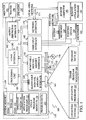
- FIG. 1 illustrates an example of a suitable computing system environment 100 on which the invention may be implemented.
- the computing system environment 100 is only one example of a suitable computing environment and is not intended to suggest any limitation as to the -scope of use or functionality of the invention. Neither should the computing environment 100 be interpreted as having any dependency or requirement relating to any one or combination of components illustrated in the exemplary operating environment 100.
- the invention is operational with numerous other general purpose or special purpose computing system environments or configurations.
- Examples of well known computing systems, environments, and/or configurations that may be suitable for use with the invention include, but are not limited to, personal computers, server computers, hand-held or laptop devices, multiprocessor systems, microprocessor-based systems, set top boxes, programmable consumer electronics, network PCs, minicomputers, mainframe computers, distributed computing environments that include any of the above systems or devices, and the like.
- the invention may be described in the general context of computer-executable instructions, such as program modules, being executed by a computer.
- program modules include routines, programs, objects, components, data structures, etc. that perform particular tasks or implement particular abstract data types.
- the invention may also be practiced in distributed computing environments where tasks are performed by remote processing devices that are linked through a communications network.
- program modules may be located in both locale and remote computer storage media including memory storage devices.
- an exemplary system for implementing the invention includes a general purpose computing device in the form of a computer 110.
- Components of computer 110 may include, but are not limited to, a processing unit 120, a system memory 130, and a system bus 121 that couples various system components including the system memory to the processing unit 120.
- the system bus 121 may be any of several types of bus structures including a memory bus or memory controller, a peripheral bus, and a locale bus using any of a variety of bus architectures.
- such architectures include Industry Standard Architecture (ISA) bus, Micro Channel Architecture (MCA) bus, Enhanced ISA (EISA) bus, Video Electronics Standards Association (VESA) locale bus, and Peripheral Component Interconnect (PCI) bus also known as Mezzanine bus.
- ISA Industry Standard Architecture
- MCA Micro Channel Architecture
- EISA Enhanced ISA
- VESA Video Electronics Standards Association
- PCI Peripheral Component Interconnect
- Computer 110 typically includes a variety of computer readable media.
- Computer readable media can be any available media that can be accessed by computer 110 and includes both volatile and nonvolatile media, removable and non-removable media.
- Computer readable media may comprise computer storage media and communication media.
- Computer storage media includes both volatile and nonvolatile, removable and non-removable media implemented in any method or technology for storage of information such as computer readable instructions, data structures, program modules or other data.
- Computer storage media includes, but is not limited to, RAM, ROM, EEPROM, flash memory or other memory technology, CD-ROM, digital versatile disks (DVD) or other optical disk storage, magnetic cassettes, magnetic tape, magnetic disk storage or other magnetic storage devices, or any other medium which can be used to store the desired information and which can be accessed by computer 100.
- Communication media typically embodies computer readable instructions, data structures, program modules or other data in a modulated data signal such as a carrier WAV or other transport mechanism and includes any information delivery media.
- modulated data signal means a signal that has one or more of its characteristics set or changed in such a manner as to encode information in the -signal.
- communication media includes wired media such as a wired network or direct-wired connection, and wireless media such as acoustic, FR, infrared and other wireless media. Combinations of any of the above should also be included within the scope of computer readable media.
- the system memory 130 includes computer storage media in the form of volatile and/or nonvolatile memory such as read only memory (ROM) 131 and random access memory (RAM) 132.
- ROM read only memory
- RAM random access memory
- BIOS basic input/output system
- RAM 132 typically contains data and/or program modules that are immediately accessible to and/or presently being operated on by processing unit 120.
- FIG. 1 illustrates operating system 134, application programs 135, other program modules 136, and program data 137.
- the computer 110 may also include other removable/non-removable volatile/nonvolatile computer storage media.
- FIG. 1 illustrates a hard disk drive 141 that reads from or writes to non-removable, nonvolatile magnetic media, a magnetic disk drive 151 that reads from or writes to a removable, nonvolatile magnetic disk 152, and an optical disk drive 155 that reads from or writes to a removable, nonvolatile optical disk 156 such as a CD ROM or other optical media.
- removable/non-removable, volatile/nonvolatile computer storage media that can be used in the exemplary operating environment include, but are not limited to, magnetic tape cassettes, flash memory cards, digital versatile disks, digital video tape, solid state RAM, solid state ROM, and the like.
- the hard disk drive 141 is typically connected to the system bus 121 through a non-removable memory interface such as interface 140, and magnetic disk drive 151 and optical disk drive 155 are typically connected to the system bus 121 by a removable memory interface, such as interface 150.
- hard disk drive 141 is illustrated as storing operating system 144, application programs 145, other program modules 146, and program data 147. Note that these components can either be the same as or different from operating system 134, application programs 135, other program modules 136, and program data 137. Operating system 144, application programs 145, other program modules 146, and program data 147 are given different numbers here to illustrate that, at a minimum, they are different copies.
- a user may enter commands and information into the computer 110 through input devices such as a keyboard 162, a microphone 163, and a pointing device 161, such as a mouse, trackball or touch pad.
- Other input devices may include a joystick, game pad, satellite dish, scanner, or the like.
- a monitor 191 or other type of display device is also connected to the system bus 121 via an interface, such as a video interface 190.
- computers may also include other peripheral output devices such as speakers 197 and printer 196, which may be connected through an output peripheral interface 190.
- the computer 110 may operate in a networked environment using logical connections to one or more remote computers, such as a remote computer 180.
- the remote computer 180 may be a personal computer, a hand-held device, a server, a router, a network PC, a peer device or other common network node, and typically includes many or all of the elements described above relative to the computer 110.
- the logical connections depicted in FIG. 1 include a locale area network (LAN) 171 and a wide area network (WAN) 173, but may also include other networks.
- LAN local area network
- WAN wide area network
- Such networking environments are commonplace in offices, enterprise-wide computer networks, intranets and the Internet.
- the computer 110 When used in a LAN networking environment, the computer 110 is connected to the LAN 171 through a network interface or adapter 170. When used in a WAN networking environment, the computer 110 typically includes a modem 172 or other means for establishing communications over the WAN 173, such as the Internet.
- the modem 172 which may be internal or external, may be connected to the system bus 121 via the user-input interface 160, or other appropriate mechanism.
- program modules depicted relative to the computer 110, or portions thereof may be stored in the remote memory storage device.
- FIG. 1 illustrates remote application programs 185 as residing on remote computer 180. It will be appreciated that the network connections shown are exemplary and other means of establishing a communications link between the computers may be used.
- the present invention can be carried out on a computer system such as that described with respect to FIG. 1 .
- the present invention can be carried out on a server, a computer devoted to message handling, or on a distributed system in which different portions of the present invention are carried out on different parts of the distributed computing system.
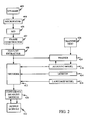
- FIG. 2 illustrates a block diagram of an exemplary speech recognition system with which the present invention can be used.
- a speaker 400 speaks into a microphone 404.
- the audio signals detected by microphone 404 are converted into electrical signals that are provided to analog-to-digital (A-to-D) converter 406.
- A-to-D analog-to-digital
- A-to-D converter 406 converts the analog signal from microphone 404 into a series of digital values. In several embodiments, A-to-D converter 406 samples the analog signal at 16 kHz and 16 bits per sample, thereby creating 32 kilobytes of speech data per second. These digital values are provided to a frame constructor 407, which, in one embodiment, groups the values into 25 millisecond frames that start 10 milliseconds apart.
- the frames of data created by frame constructor 407 are provided to feature extractor 408, which extracts a feature from each frame.
- feature extraction modules include modules for performing Linear Predictive Coding (LPC), LPC derived cepstrum, Perceptive Linear Prediction (PLP), Auditory model feature extraction, and Mel-Frequency Cepstrum Coefficients (MFCC) feature extraction. Note that the invention is not limited to these feature extraction modules and that other modules may be used within the context of the present invention.
- the feature extraction module 408 produces a stream of feature vectors that are each associated with a frame of the speech signal.
- This stream of feature vectors is provided to a decoder 412, which identifies a most likely sequence of words based on the stream of feature vectors, a lexicon 414, a language model 416 (for example, based on an N-gram, context-free grammars, or hybrids thereof), and the acoustic model 418.
- the particular method used for decoding is not important to the present invention. However, aspects of the present invention include modifications to the acoustic model 418 and the use thereof.
- the most probable sequence of hypothesis words can be provided to an optional confidence measure module 420.
- Confidence measure module 420 identifies which words are most likely to have been improperly identified by the speech recognizer. This can be based in part on a secondary acoustic model (not shown). Confidence measure module 420 then provides the sequence of hypothesis words to an output module 422 along with identifiers indicating which words may have been improperly identified. Those skilled in the art will recognize that confidence measure module 420 is not necessary for the practice of the present invention.
- a speech signal corresponding to training text 426 is input to decoder 412, along with a lexical transcription of the training text 426.
- Trainer 424 trains acoustic model 418 based on the training inputs.
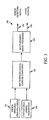
- FIG. 3 illustrates a speech detection system 300 in accordance with one embodiment of the present invention.
- Speech detection system 300 includes speech sensor or transducer 301, conventional audio microphone 303, multi-sensory signal capture component 302 and multi-sensory signal processor 304.
- Capture component 302 captures signals from conventional microphone 303 in the form of an audio signal.
- Component 302 also captures an input signal from speech transducer 301 which is indicative of whether a user is speaking.
- the signal generated from this transducer can be generated from a wide variety of other transducers.
- the transducer is an infrared sensor that is generally aimed at the user's face, notably the mouth region, and generates a signal indicative of a change in facial movement of the user that corresponds to speech.
- the sensor includes a plurality of infrared emitters and sensors aimed at different portions of the user's face.
- the speech sensor or sensors 301 can include a throat microphone which measures the impedance across the user's throat or throat vibration.
- the sensor is a bone vibration sensitive microphone which is located adjacent a facial or skull bone of the user (such as the jaw bone) and senses vibrations that correspond to speech generated by the user. This type of sensor can also be placed in contact with the throat, or adjacent to, or within, the user's ear.
- a temperature sensor such as a thermistor is placed in the breath stream such as on the same support that holds the regular microphone. As the user speaks, the exhaled breath causes a change in temperature in the sensor and thus detecting speech.
- the transducer 301 is illustratively highly insensitive to background speech but strongly indicative of whether the user is speaking.
- component 302 captures the signals from the transducers 301 and the microphone 303 and converts them into digital form, as a synchronized time series of signal samples. Component 302 then provides one or more outputs to multi-sensory signal processor 304.
- Processor 304 processes the input signals captured by component 302 and provides, at its output, speech detection signal 306 which is indicative of whether the user is speaking.
- Processor 304 can also optionally output additional signals 308, such as an audio output signal, or such as speech detection signals that indicate a likelihood or probability that the user is speaking based on signals from a variety of different transducers.
- Other outputs 308 will illustratively vary based on the task to be performed. However, in one embodiment, outputs 308 include an enhanced audio signal that is used in a speech recognition system.
- FIG. 4 illustrates one embodiment of multi-sensory signal processor 304 in greater detail.
- processor 304 will be described with reference to the transducer input from transducer 301 being an infrared signal generated from an infrared sensor located proximate the user's face. It will be appreciated, of course, that the description of FIG. 4 could just as easily be with respect to the transducer signal being from a throat sensor, a vibration sensor, etc.
- FIG. 4 shows that processor 304 includes infrared (IR)-based speech detector 310, audio-based speech detector 312, and combined speech detection component 314.
- IR-based speech detector 310 receives the IR signal emitted by an IR emitter and reflected off the speaker and detects whether the user is speaking based on the IR signal.
- Audio-based speech detector 312 receives the audio signal and detects whether the user is speaking based on the audio signal.
- the output from detectors 310 and 312 are provided to combined speech detection component 314.
- Component 314 receives the signals and makes an overall estimation as to whether the user is speaking based on the two input signals.
- the output from component 314 comprises the speech detection signal 306.
- speech detection signal 306 is provided to background speech removal component 316. Speech detection signal 306 is used to indicate when, in the audio signal, -the user is actually speaking.
- the two independent detectors 310 and 312 each generate a probabilistic description of how likely it is that the user is talking.
- the output of IR-based speech detector 310 is a probability that the user is speaking, based on the IR-input signal.
- the output signal from audio-based speech detector 312 is a probability that the user is speaking based on the audio input signal.
- Signal 306 can be used to further process the audio signal in component 316 to remove background speech.
- signal 306 is simply used to provide the speech signal to the speech recognition engine through component 316 when speech detection signal 306 indicates that the user is speaking. If speech detection -signal 306 indicates that the user is not speaking, then the speech signal is not provided through .component 316 to the speech recognition engine.
- component 314 provides speech detection signal 306 as a probability measure indicative of a probability that the user is speaking.
- the audio signal is multiplied in component 316 by the probability embodied in speech detection signal 306. Therefore, when the probability that the user is speaking is high, the speech signal provided to the speech recognition engine through component 316 also has a large magnitude. However, when the probability that the user is speaking is low, the speech signal provided to the speech recognition engine through component 316 has a very low magnitude.
- the speech detection signal 306 can simply be provided directly to the speech recognition engine which, itself, can determine whether the user is speaking and how to process the speech signal based on that determination.
- FIG. 5 illustrates another embodiment of multi-sensory signal processor 304 in more detail.
- processor 304 is formed of a single fused speech detector 320.
- Detector 320 receives both the IR signal and the audio signal and makes a determination, based on both signals, whether the user is speaking.
- features are first extracted independently from the infrared and audio signals, and those features are fed into the detector 320. Based on the features received, detector 320 detects whether the user is speaking and outputs speech detection signal 306, accordingly.
- the speech detectors can be generated and trained using training data in which a noisy audio signal is provided, along with the IR signal, and also along with a manual indication (such as a push-to-talk signal) that indicates specifically whether the user is speaking.
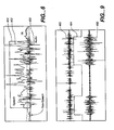
- FIG. 6 shows a plot of an audio signal 400 and an infrared signal 402, in terms of magnitude versus time.
- FIG. 6 also shows speech detection signal 404 that indicates when the user is speaking. When in a logical high state, signal 404 is indicative of a decision by the speech detector that the speaker is speaking. When in a logical low state, signal 404 indicates that the user is not speaking.
- the mean and variance of the signals 400 and 402 are computed periodically, such as every 100 milliseconds. The mean and variance computations are used as baseline mean and variance values against which speech detection decisions are made.
- both the audio signal 400 and infrared signal 402 have a larger variance when the user is speaking, than when the user is not speaking. Therefore, when observations are processed, such as every 5-10 milliseconds, the mean and variance (or just the variance) of the signal during the observation is compared to the baseline mean and variance (or just the baseline variance). If the observed values are larger than the baseline values, then it is determined that the user is speaking. If not, then it is -determined that the user is not speaking. In one illustrative embodiment, the speech detection determination is made based on whether the observed values exceed the baseline values by a predetermined threshold. For example, during each observation, if the infrared signal is not within three standard deviations of the baseline mean, it is considered that the user is speaking. The same can be used for the audio signal.
- the detectors 310, 312, 314 or 320 can also adapt during use, such as to accommodate for changes in ambient light conditions, or such as for changes in the head position of the user, which may cause slight changes in lighting that affect the IR signal.
- the baseline mean and variance values can be re-estimated every 5-10 seconds, for example, or using another revolving time window. This allows those values to be updated to reflect changes over time. Also, before the baseline mean and variance are updated using the moving window, it can first be determined whether the input signals correspond to the user speaking or not speaking. The mean and variance can be recalculated using only portions of the signal that correspond to the user not speaking
- the IR signal may generally precede the audio signal. This is because the user may, in general, change mouth or face positions prior to producing any sound. Therefore, this allows the system to detect speech even before the speech signal is available.
- FIG. 7 is a pictorial illustration of one embodiment of an IR sensor and audio microphone in accordance with the present invention.
- a headset 420 is provided with a pair of headphones 422 and 424, along with a boom 426.
- Boom 426 has at its distal end a conventional audio microphone 428, along with an infrared transceiver 430.
- Transceiver 430 can illustratively be an infrared light emitting diode (LED) and an infrared receiver.
- LED infrared light emitting diode
- FIG. 6 As the user is moving his or her face, notably mouth, during speech, the light reflected back from the user's face, notably mouth, and represented in the IR sensor signal will change, as illustrated in FIG. 6 . Thus, it can be determined whether the user is speaking based on the IR sensor signal.
- the present invention contemplates the use of multiple infrared transceivers as well.
- the probabilities associated with the IR signals generated from each infrared transceiver can be processed separately or simultaneously. If they are processed separately, simple voting logic can be used to determine whether the infrared signals indicate that the speaker i-s speaking. Alternatively, a probabilistic model can be used to determine whether the user is speaking based upon multiple IR signals.
- FIG. 8 is a pictorial illustration of a headset 450 that includes a head mount 451 with earphones 452 and 454, as well as a conventional audio microphone 456, and in addition, a bone sensitive microphone 458. Both microphones 456 and 458 can be mechanically and even rigidly connected to the head mount 451.
- the bone sensitive microphone 458 converts the vibrations in facial bones as they travel through the speaker's skull into electronic voice signals. These types of microphones are known and are commercially available in a variety of shapes and sizes.
- Bone sensitive microphone 458 is typically formed as a contact microphone that is worn on the top of the skull or behind the ear (to contact the mastoid). The bone conductive microphone is sensitive to vibrations of the bones, and is much less sensitive to external voice sources.
- FIG. 9 illustrates a plurality of signals including the signal 460 from conventional microphone 456, the signal 462 from the bone sensitive microphone 458 and a binary speech detection signal 464 which corresponds to the output of a speech detector.
- signal 464 When signal 464 is in a logical high state, it indicates that the detector has determined that the speaker is speaking. When it is in a logical low state, it corresponds to the decision that the speaker is not speaking.
- the signals in FIG. 9 were captured from an environment in which data was collected while a user was wearing the microphone system shown in FIG. 8 , with background audio playing.
- the audio signal 460 shows significant activity even when the user is not speaking.
- the bone sensitive microphone signal 462 shows negligible signal activity accept when the user is actually speaking. It can thus be seen that, considering only audio signal 460, it is very difficult to determine whether the user is actually speaking. However, when using the signal from the bone sensitive microphone, either alone or in conjunction with the audio signal, it becomes much easier to determine when the user is speaking.
- FIG. 10 shows another embodiment of the present invention in which a headset 500 includes a head mount 501, an earphone 502 along with a conventional audio microphone 504, and a throat microphone 506.
- Both microphones 504 and 506 are mechanically connected to head mount 501, and can be rigidly connected to it.
- throat microphones There are a variety of different throat microphones that can be used. For example, there are currently single element and dual element designs. Both function by sensing vibrations of the throat and converting the vibrations into microphone signals.
- Throat microphones are illustratively worn around the neck and held in place by an elasticized strap or neckband. They perform well when the sensing elements are positioned at either side of a user's "Adams apple" over the user's voice box.
- FIG. 11 shows another embodiment of the present invention in which a headset 550 includes an in-ear microphone 552 along with a conventional audio microphone 554.
- in-ear microphone 552 is integrated with an earphone 554.
- the earphone could form a separate component, separate from in-ear microphone 552.
- FIG. 11 also shows that conventional audio microphone 554 is embodied as a close-talk microphone connected to in-ear microphone 552 by a boom 556. Boom 556 can be rigid or flexible.
- the head mount portion of the headset comprises the in-ear microphone 552 and optional earphone 554 which mount headset 550 to the speaker's head through frictional connection with the interior of the speaker's ear.
- the in-ear microphone 552 senses voice vibrations which are transmitted through the speaker's ear canal, or through the bones surrounding the speaker's ear canal, or both.
- the system works in a similar way to the headset with the bone sensitive microphone 458 shown in FIG. 8 .
- the voice vibrations sensed by in-ear microphone 552 are converted to microphone signals which are used in down-stream processing.
- speech sensors or transducers 301 While a number of embodiments of speech sensors or transducers 301 have been described, it will be appreciated that -other speech sensors or transducers can be used as well. For example, charge coupled devices (or digital cameras) can be used in a similar way to the IR sensor. Further, laryngeal sensors can be used as well. The above embodiments are described for the sake of example only.
- a histogram is maintained of all the variances for the most recent frames within a user specified amount of time (such as within one minute, etc.). For each observation frame thereafter, the variance is computed for the input signals and compared to the histogram values to determine whether a current frame represents that the speaker is speaking or not speaking. The histogram is then updated. It should be noted that if the current frame is simply inserted into the histogram and the oldest frame is removed, then the histogram may represent only the speaking frames in situations where a user is speaking for a long period of time.
- the number of speaking and nonspeaking frames in the histogram is tracked, and the histogram is selectively updated. If a current frame is classified as speaking, while the number of speaking frames in the histogram is more than half of the total number of frames, then the current frame is simply not inserted in the histogram.
- other updating techniques can be used as well and this is given for exemplary purposes only.
- the present system can be used in a wide variety of applications. For example, many present push-to-talk systems require the user to press and hold an input actuator (such as a button) in order to interact with speech modes. Usability studies have indicated that users have difficulty manipulating these satisfactorily. Similarly, users begin to speak concurrently with pressing the hardware buttons, leading to the clipping at the beginning of an utterance. Thus, the present system can simply be used in speech recognition, in place of push-to-talk systems.
- an input actuator such as a button
- the present invention can be used to remove background speech.
- Background speech has been identified as an extremely common noise source, followed by phones ringing and air conditioning.
- the present speech detection signal as set out above, much of this background noise can be eliminated.
- variable-rate speech coding systems can be improved. Since the present invention provides an output indicative of whether the user is speaking, a much more efficient speech coding system can be employed. Such a system reduces the bandwidth requirements in audio conferencing because speech coding is only performed when a user is actually speaking.
- power management for personal digital assistants or small computing devices can be improved.
- Battery life is a major concern in such portable devices.
- the audio signal from the conventional audio microphone and the signal from the speech sensor can be combined in an intelligent way such that the background speech can be eliminated from the audio signal even when the background speaker talks at the same time as the speaker of interest.
- the ability of performing such speech enhancement may be highly desired in certain circumstances.
Landscapes
- Engineering & Computer Science (AREA)
- Physics & Mathematics (AREA)
- Acoustics & Sound (AREA)
- Health & Medical Sciences (AREA)
- Audiology, Speech & Language Pathology (AREA)
- Human Computer Interaction (AREA)
- Multimedia (AREA)
- Computational Linguistics (AREA)
- Signal Processing (AREA)
- Theoretical Computer Science (AREA)
- General Health & Medical Sciences (AREA)
- General Engineering & Computer Science (AREA)
- General Physics & Mathematics (AREA)
- User Interface Of Digital Computer (AREA)
- Circuit For Audible Band Transducer (AREA)
- Details Of Audible-Bandwidth Transducers (AREA)
- Stereophonic System (AREA)
- Telephone Set Structure (AREA)
Claims (5)
- Spracherkennungssystem, das umfasst:ein Audio-Mikrofon (303, 312, 428, 456, 504, 554), das ein Mikrofon-Signal (400) auf Basis eines erfassten Audio-Eingangs ausgibt, wobei das Mikrofon-Signal eine Wahrscheinlichkeit anzeigt, dass der Benutzer spricht;einen Temperatur-Sensor (301), der in einem Atemstrom auf dem selben Träger angeordnet ist, der das Audio-Mikrofon trägt, wobei der Temperatur-Sensor ein SensorSignal (402) ausgibt, das eine Wahrscheinlichkeit anzeigt, dass der Benutzer spricht, und der Temperatur-Sensor empfindlich für eine Temperaturänderung aufgrund von Atem ist, der ausgestoßen wird, wenn der Benutzer spricht;eine Sprachdetektor-Komponente (304, 314), die ein Spracherfassungs-Signal (306, 404) ausgibt, das auf Basis des Sensor-Signals und des Mikrofon-Signals eine Wahrscheinlichkeit anzeigt, dass der Benutzer spricht, und die eine binäre Entscheidung dahingehend trifft, ob der Benutzer spricht oder nicht, indem sie:Varianzen des Mikrofon-Signals und des Sensor-Signals mit Baseline-Varianzwerten vergleicht, die periodisch berechnet werden, indem ein Wert jeder Varianz über einen Zeitraum gemittelt wird;feststellt, dass der Benutzer spricht, wenn die Varianzen des Mikrofon-Signals und des Sensor-Signals größer sind als die entsprechenden Baseline-Varianzwerte; undansonsten feststellt, dass der Benutzer nicht spricht;eine Komponente (316) zum Entfernen von Hintergrundsprache, die ein kombiniertes - Signal berechnet, indem sie das Spracherfassungs-Signal mit dem Mikrofon-Signal multipliziert; undeine Spracherkennungseinrichtung, die Sprache erkennt, um einen Erkennungs-Ausgang bereitzustellen, der auf Basis des kombinierten Signals Sprache in dem erfassten Audio-Eingang anzeigt, wobei eine Mutmaßlichkeit (likelihood), dass Sprache erkannt wird, mit der Wahrscheinlichkeit zunimmt, dass der Benutzer spricht.
- Spracherkennungssystem nach Anspruch 1, wobei der Vergleich der Varianz des Sensor-Signals mit dem Baseline-Varianzwert des Sensor-Signals periodisch durchgeführt wird.
- Spracherkennungssystem nach Anspruch 2, wobei der Vergleich häufiger durchgeführt wird als der Baseline-Varianzwert des Sensor-Signals neu berechnet wird.
- Spracherkennungssystem nach Anspruch 1, wobei das Audio-Mikrofon und der Sprach-Sensor an einer Sprechgarnitur angebracht sind.
- Verfahren zum Erkennen von Sprache, das umfasst:Erzeugen eines Mikrofon-Signals (400), das eine Audio-Eingabe anzeigt, mit einem Audio-Mikrofon (303, 312, 428, 456, 504, 554), wobei das Mikrofon-Signal eine Wahrscheinlichkeit anzeigt, dass ein Benutzer spricht;Erzeugen eines Sensor-Signals (402), das eine Wahrscheinlichkeit anzeigt, dass der Benutzer spricht, mit einem Temperatur-Sensor (301), der in einem Atemstrom auf dem selben Träger angeordnet ist, der das Audio-Mikrofon trägt, wobei der Temperatur-Sensor empfindlich für eine Temperaturänderung aufgrund von Atem ist, der ausgestoßen wird, wenn der Benutzer spricht;Erzeugen eines Spracherfassungs-Signals (306, 404), das auf Basis des Mikrofon-Signals und des Sensor-Signals eine Wahrscheinlichkeit anzeigt, dass der Benutzer spricht;Treffen einer binären Entscheidung dahingehend, ob der Benutzer spricht oder nicht, indem:Varianzen des Mikrofon-Signals und des Sensor-Signals mit Baseline-Varianzwerten verglichen werden, die periodisch berechnet werden, indem ein Wert der Varianz über einen Zeitraum gemittelt wird;festgestellt wird, dass der Benutzer spricht, wenn die Varianzen des Mikrofon-Signals und des Sensor-Signals größer sind als die entsprechenden Baseline-Varianzwerte; undansonsten festgestellt wird, dass der Benutzer nicht spricht;Erzeugen eines kombinierten Signals durch Multiplizieren des Spracherfassungs-Signals mit dem Mikrofon-Signal; undErkennen von Sprache auf Basis des kombinierten Signals, wobei eine Mutmaßlichkeit (likelihood), dass Sprache erkannt wird, mit der Wahrscheinlichkeit zunimmt, dass der Benutzer spricht.
Applications Claiming Priority (4)
| Application Number | Priority Date | Filing Date | Title |
|---|---|---|---|
| US10/629,278 US7383181B2 (en) | 2003-07-29 | 2003-07-29 | Multi-sensory speech detection system |
| US629278 | 2003-07-29 | ||
| US636176 | 2003-08-07 | ||
| US10/636,176 US20050033571A1 (en) | 2003-08-07 | 2003-08-07 | Head mounted multi-sensory audio input system |
Publications (2)
| Publication Number | Publication Date |
|---|---|
| EP1503368A1 EP1503368A1 (de) | 2005-02-02 |
| EP1503368B1 true EP1503368B1 (de) | 2010-06-16 |
Family
ID=33544784
Family Applications (1)
| Application Number | Title | Priority Date | Filing Date |
|---|---|---|---|
| EP04016226A Expired - Lifetime EP1503368B1 (de) | 2003-07-29 | 2004-07-09 | Am Kopf angebrachtes Audioeingabesystem mit mehreren Sensoren |
Country Status (13)
| Country | Link |
|---|---|
| EP (1) | EP1503368B1 (de) |
| JP (1) | JP4703142B2 (de) |
| KR (1) | KR101098601B1 (de) |
| CN (1) | CN100573664C (de) |
| AT (1) | ATE471554T1 (de) |
| AU (1) | AU2004203357B2 (de) |
| BR (1) | BRPI0403027A (de) |
| CA (1) | CA2473195C (de) |
| DE (1) | DE602004027687D1 (de) |
| MX (1) | MXPA04007313A (de) |
| MY (1) | MY138807A (de) |
| RU (1) | RU2363994C2 (de) |
| TW (1) | TWI383377B (de) |
Cited By (1)
| Publication number | Priority date | Publication date | Assignee | Title |
|---|---|---|---|---|
| WO2016153700A1 (en) * | 2015-03-24 | 2016-09-29 | Intel Corporation | Voice activity detection technologies, systems and methods employing the same |
Families Citing this family (41)
| Publication number | Priority date | Publication date | Assignee | Title |
|---|---|---|---|---|
| JP4667082B2 (ja) | 2005-03-09 | 2011-04-06 | キヤノン株式会社 | 音声認識方法 |
| EP1894330B1 (de) * | 2005-06-13 | 2018-02-21 | Technion Research and Development Ltd. | System zum Detektieren von Schall, der von einer Stimme eines Nutzers ausgeht, wobei ein Interferometer genutzt wird |
| RU2385706C2 (ru) * | 2005-09-20 | 2010-04-10 | Станислав Степанович Лиманский | Виброфон и способ управления фонацией |
| JP2007171637A (ja) * | 2005-12-22 | 2007-07-05 | Toshiba Tec Corp | 音声処理装置 |
| JP2007267331A (ja) * | 2006-03-30 | 2007-10-11 | Railway Technical Res Inst | 発話音声収集用コンビネーション・マイクロフォンシステム |
| CN100583006C (zh) * | 2006-12-13 | 2010-01-20 | 鸿富锦精密工业(深圳)有限公司 | 具有摇动响应机制的音乐播放装置 |
| JP2010010869A (ja) * | 2008-06-25 | 2010-01-14 | Audio Technica Corp | マイクロホン装置 |
| JP5499633B2 (ja) * | 2009-10-28 | 2014-05-21 | ソニー株式会社 | 再生装置、ヘッドホン及び再生方法 |
| US8626498B2 (en) | 2010-02-24 | 2014-01-07 | Qualcomm Incorporated | Voice activity detection based on plural voice activity detectors |
| US9025782B2 (en) * | 2010-07-26 | 2015-05-05 | Qualcomm Incorporated | Systems, methods, apparatus, and computer-readable media for multi-microphone location-selective processing |
| FR2976111B1 (fr) * | 2011-06-01 | 2013-07-05 | Parrot | Equipement audio comprenant des moyens de debruitage d'un signal de parole par filtrage a delai fractionnaire, notamment pour un systeme de telephonie "mains libres" |
| FR2982451A1 (fr) * | 2011-11-03 | 2013-05-10 | Joel Pedre | Speak world 3 ou traducteur verbal integre et amplifie a emetteur infrarouge et a micro intra auriculaire |
| EP2893532B1 (de) | 2012-09-03 | 2021-03-24 | Fraunhofer-Gesellschaft zur Förderung der Angewandten Forschung e.V. | Vorrichtung und verfahren für informierte mehrkanalige sprachpräsenzwahrscheinlichkeitsschätzung |
| GB2513559B8 (en) * | 2013-04-22 | 2016-06-29 | Ge Aviat Systems Ltd | Unknown speaker identification system |
| CN104123930A (zh) * | 2013-04-27 | 2014-10-29 | 华为技术有限公司 | 喉音识别方法及装置 |
| KR102282366B1 (ko) | 2013-06-03 | 2021-07-27 | 삼성전자주식회사 | 음성 향상 방법 및 그 장치 |
| CN103309642A (zh) * | 2013-06-09 | 2013-09-18 | 张家港市鸿嘉数字科技有限公司 | 一种识别声音操作平板电脑的方法 |
| US9589565B2 (en) | 2013-06-21 | 2017-03-07 | Microsoft Technology Licensing, Llc | Environmentally aware dialog policies and response generation |
| US9311298B2 (en) | 2013-06-21 | 2016-04-12 | Microsoft Technology Licensing, Llc | Building conversational understanding systems using a toolset |
| US9564128B2 (en) * | 2013-12-09 | 2017-02-07 | Qualcomm Incorporated | Controlling a speech recognition process of a computing device |
| US9674599B2 (en) * | 2014-03-07 | 2017-06-06 | Wearhaus, Inc. | Headphones for receiving and transmitting audio signals |
| FR3019423B1 (fr) * | 2014-03-25 | 2017-07-21 | Elno | Circuit electronique pour bandeau osteophonique |
| US9529794B2 (en) * | 2014-03-27 | 2016-12-27 | Microsoft Technology Licensing, Llc | Flexible schema for language model customization |
| US9706294B2 (en) * | 2015-03-18 | 2017-07-11 | Infineon Technologies Ag | System and method for an acoustic transducer and environmental sensor package |
| CN104766610A (zh) * | 2015-04-07 | 2015-07-08 | 马业成 | 基于振动的声音识别系统和识别方法 |
| JP6500625B2 (ja) * | 2015-06-16 | 2019-04-17 | カシオ計算機株式会社 | 検知装置、検知システム、検知方法及びプログラム |
| EP3185244B1 (de) | 2015-12-22 | 2019-02-20 | Nxp B.V. | Sprachaktivierungssystem |
| CN107734416B (zh) * | 2017-10-11 | 2024-01-09 | 深圳市三诺数字科技有限公司 | 一种激光面纹识别降噪装置、耳机及方法 |
| CN108735219B (zh) * | 2018-05-09 | 2021-08-31 | 深圳市宇恒互动科技开发有限公司 | 一种声音识别控制方法及装置 |
| CN108766468B (zh) * | 2018-06-12 | 2021-11-02 | 歌尔科技有限公司 | 一种智能语音检测方法、无线耳机、tws耳机及终端 |
| CN115150705B (zh) * | 2018-11-27 | 2025-07-04 | 谷歌有限责任公司 | 自动切换活动麦克风的系统、方法和计算机可读介质 |
| CN109410957B (zh) * | 2018-11-30 | 2023-05-23 | 福建实达电脑设备有限公司 | 基于计算机视觉辅助的正面人机交互语音识别方法及系统 |
| RU2719659C1 (ru) * | 2019-01-10 | 2020-04-21 | Общество с ограниченной ответственностью "Центр речевых технологий" (ООО "ЦРТ") | Устройство для регистрации и управления вводом речевой информации |
| US11488583B2 (en) * | 2019-05-30 | 2022-11-01 | Cirrus Logic, Inc. | Detection of speech |
| JP7331523B2 (ja) * | 2019-07-24 | 2023-08-23 | 富士通株式会社 | 検出プログラム、検出方法、検出装置 |
| JP7378770B2 (ja) * | 2019-08-27 | 2023-11-14 | 国立大学法人静岡大学 | 評価装置、評価方法、及び評価プログラム |
| US11647950B2 (en) * | 2020-03-30 | 2023-05-16 | Sonova Ag | Hearing device with optical sensor at spout |
| DK180847B1 (en) * | 2020-06-15 | 2022-05-17 | Gn Hearing As | HEARING DEVICE WITH SPEECH SYNTHESIS AND RELATED PROCEDURE |
| EP4131256A1 (de) * | 2021-08-06 | 2023-02-08 | STMicroelectronics S.r.l. | Spracherkennungssystem und -verfahren unter verwendung von beschleunigungsmessern zur erfassung der knochenleitung |
| CN113810819B (zh) * | 2021-09-23 | 2022-06-28 | 中国科学院软件研究所 | 一种基于耳腔振动的静默语音采集处理方法及设备 |
| CN115567821B (zh) * | 2022-09-26 | 2025-09-19 | 歌尔科技有限公司 | 耳机设备控制方法、装置、设备及计算机可读存储介质 |
Family Cites Families (18)
| Publication number | Priority date | Publication date | Assignee | Title |
|---|---|---|---|---|
| US3383466A (en) * | 1964-05-28 | 1968-05-14 | Navy Usa | Nonacoustic measures in automatic speech recognition |
| SU544990A1 (ru) * | 1974-04-08 | 1977-01-30 | Устройство дл распознавани речи | |
| JPH04184495A (ja) * | 1990-11-20 | 1992-07-01 | Seiko Epson Corp | 音声認識装置 |
| TW219993B (en) * | 1992-05-21 | 1994-02-01 | Ind Tech Res Inst | Speech recognition system |
| US5625697A (en) * | 1995-05-08 | 1997-04-29 | Lucent Technologies Inc. | Microphone selection process for use in a multiple microphone voice actuated switching system |
| US5647834A (en) * | 1995-06-30 | 1997-07-15 | Ron; Samuel | Speech-based biofeedback method and system |
| US6006175A (en) * | 1996-02-06 | 1999-12-21 | The Regents Of The University Of California | Methods and apparatus for non-acoustic speech characterization and recognition |
| TW404103B (en) * | 1998-06-02 | 2000-09-01 | Inventec Corp | Telephone answering system which is capable of transmitting image and audio data |
| JP3893763B2 (ja) | 1998-08-17 | 2007-03-14 | 富士ゼロックス株式会社 | 音声検出装置 |
| US6594629B1 (en) | 1999-08-06 | 2003-07-15 | International Business Machines Corporation | Methods and apparatus for audio-visual speech detection and recognition |
| JP2001292489A (ja) * | 2000-04-10 | 2001-10-19 | Kubota Corp | 骨伝導マイク付きヘッドホン |
| WO2002077972A1 (en) | 2001-03-27 | 2002-10-03 | Rast Associates, Llc | Head-worn, trimodal device to increase transcription accuracy in a voice recognition system and to process unvocalized speech |
| US6671379B2 (en) * | 2001-03-30 | 2003-12-30 | Think-A-Move, Ltd. | Ear microphone apparatus and method |
| TW541824B (en) * | 2001-05-29 | 2003-07-11 | Inventec Multimedia & Telecom | Multi-channel voice conferencing equipment and method there for |
| JP2002358089A (ja) * | 2001-06-01 | 2002-12-13 | Denso Corp | 音声処理装置及び音声処理方法 |
| US6707921B2 (en) * | 2001-11-26 | 2004-03-16 | Hewlett-Packard Development Company, Lp. | Use of mouth position and mouth movement to filter noise from speech in a hearing aid |
| US20050141730A1 (en) * | 2001-12-21 | 2005-06-30 | Rti Tech Pte Ltd. | Vibration-based talk-through method and apparatus |
| US7219062B2 (en) * | 2002-01-30 | 2007-05-15 | Koninklijke Philips Electronics N.V. | Speech activity detection using acoustic and facial characteristics in an automatic speech recognition system |
-
2004
- 2004-07-07 CA CA2473195A patent/CA2473195C/en not_active Expired - Fee Related
- 2004-07-09 MY MYPI20042739A patent/MY138807A/en unknown
- 2004-07-09 EP EP04016226A patent/EP1503368B1/de not_active Expired - Lifetime
- 2004-07-09 AT AT04016226T patent/ATE471554T1/de not_active IP Right Cessation
- 2004-07-09 DE DE602004027687T patent/DE602004027687D1/de not_active Expired - Lifetime
- 2004-07-20 TW TW093121624A patent/TWI383377B/zh not_active IP Right Cessation
- 2004-07-22 AU AU2004203357A patent/AU2004203357B2/en not_active Ceased
- 2004-07-27 BR BR0403027-3A patent/BRPI0403027A/pt not_active IP Right Cessation
- 2004-07-28 KR KR1020040059346A patent/KR101098601B1/ko not_active Expired - Fee Related
- 2004-07-28 MX MXPA04007313A patent/MXPA04007313A/es active IP Right Grant
- 2004-07-28 JP JP2004220690A patent/JP4703142B2/ja not_active Expired - Fee Related
- 2004-07-28 RU RU2004123352/09A patent/RU2363994C2/ru not_active IP Right Cessation
- 2004-07-29 CN CNB2004100557384A patent/CN100573664C/zh not_active Expired - Fee Related
Cited By (1)
| Publication number | Priority date | Publication date | Assignee | Title |
|---|---|---|---|---|
| WO2016153700A1 (en) * | 2015-03-24 | 2016-09-29 | Intel Corporation | Voice activity detection technologies, systems and methods employing the same |
Also Published As
| Publication number | Publication date |
|---|---|
| CA2473195C (en) | 2014-02-04 |
| CN100573664C (zh) | 2009-12-23 |
| BRPI0403027A (pt) | 2005-05-31 |
| AU2004203357B2 (en) | 2010-01-28 |
| ATE471554T1 (de) | 2010-07-15 |
| AU2004203357A1 (en) | 2005-02-17 |
| KR101098601B1 (ko) | 2011-12-23 |
| DE602004027687D1 (de) | 2010-07-29 |
| CA2473195A1 (en) | 2005-01-29 |
| KR20050013969A (ko) | 2005-02-05 |
| MY138807A (en) | 2009-07-31 |
| HK1073010A1 (en) | 2005-09-16 |
| RU2363994C2 (ru) | 2009-08-10 |
| EP1503368A1 (de) | 2005-02-02 |
| RU2004123352A (ru) | 2006-01-27 |
| TW200519834A (en) | 2005-06-16 |
| JP4703142B2 (ja) | 2011-06-15 |
| JP2005049876A (ja) | 2005-02-24 |
| MXPA04007313A (es) | 2005-07-26 |
| CN1591568A (zh) | 2005-03-09 |
| TWI383377B (zh) | 2013-01-21 |
Similar Documents
| Publication | Publication Date | Title |
|---|---|---|
| EP1503368B1 (de) | Am Kopf angebrachtes Audioeingabesystem mit mehreren Sensoren | |
| US7383181B2 (en) | Multi-sensory speech detection system | |
| US20050033571A1 (en) | Head mounted multi-sensory audio input system | |
| US20230045237A1 (en) | Wearable apparatus for active substitution | |
| JP4796309B2 (ja) | モバイル・デバイス上のマルチセンサによるスピーチ改良のための方法および装置 | |
| Nakajima et al. | Non-audible murmur (NAM) recognition | |
| CN111935573B (zh) | 音频增强方法、装置、存储介质及可穿戴设备 | |
| US20040243416A1 (en) | Speech recognition | |
| Zhang et al. | Multi-sensory microphones for robust speech detection, enhancement and recognition | |
| CN111475206B (zh) | 用于唤醒可穿戴设备的方法及装置 | |
| US20140214426A1 (en) | System and method for improving voice communication over a network | |
| CN113748462A (zh) | 确定用于语音处理引擎的输入 | |
| US4718096A (en) | Speech recognition system | |
| CN107799126A (zh) | 基于有监督机器学习的语音端点检测方法及装置 | |
| JP2012510088A (ja) | 音声推定インタフェースおよび通信システム | |
| JP3838159B2 (ja) | 音声認識対話装置およびプログラム | |
| US20150039314A1 (en) | Speech recognition method and apparatus based on sound mapping | |
| CN120412578A (zh) | 一种基于环境声的智能音量调节方法及系统 | |
| HK1073010B (en) | Head mounted multi-sensory audio input system | |
| JP2000206986A (ja) | 言語情報検出装置 | |
| Vacher et al. | Recognition of distress calls in distant speech setting: a preliminary experiment in a smart home | |
| WO2024019759A1 (en) | Controlling head-mounted devices by voiced nasal consonants | |
| CN120343469A (zh) | 工作模式的切换方法、系统、头戴式设备和介质 | |
| JPH01310399A (ja) | 音声認識装置 | |
| CN111445912A (zh) | 语音处理方法和系统 |
Legal Events
| Date | Code | Title | Description |
|---|---|---|---|
| PUAI | Public reference made under article 153(3) epc to a published international application that has entered the european phase |
Free format text: ORIGINAL CODE: 0009012 |
|
| AK | Designated contracting states |
Kind code of ref document: A1 Designated state(s): AT BE BG CH CY CZ DE DK EE ES FI FR GB GR HU IE IT LI LU MC NL PL PT RO SE SI SK TR |
|
| AX | Request for extension of the european patent |
Extension state: AL HR LT LV MK |
|
| 17P | Request for examination filed |
Effective date: 20050630 |
|
| REG | Reference to a national code |
Ref country code: HK Ref legal event code: DE Ref document number: 1073010 Country of ref document: HK |
|
| AKX | Designation fees paid |
Designated state(s): AT BE BG CH CY CZ DE DK EE ES FI FR GB GR HU IE IT LI LU MC NL PL PT RO SE SI SK TR |
|
| 17Q | First examination report despatched |
Effective date: 20081119 |
|
| GRAP | Despatch of communication of intention to grant a patent |
Free format text: ORIGINAL CODE: EPIDOSNIGR1 |
|
| GRAS | Grant fee paid |
Free format text: ORIGINAL CODE: EPIDOSNIGR3 |
|
| GRAA | (expected) grant |
Free format text: ORIGINAL CODE: 0009210 |
|
| AK | Designated contracting states |
Kind code of ref document: B1 Designated state(s): AT BE BG CH CY CZ DE DK EE ES FI FR GB GR HU IE IT LI LU MC NL PL PT RO SE SI SK TR |
|
| REG | Reference to a national code |
Ref country code: CH Ref legal event code: EP |
|
| REG | Reference to a national code |
Ref country code: IE Ref legal event code: FG4D |
|
| REF | Corresponds to: |
Ref document number: 602004027687 Country of ref document: DE Date of ref document: 20100729 Kind code of ref document: P |
|
| REG | Reference to a national code |
Ref country code: NL Ref legal event code: VDEP Effective date: 20100616 |
|
| PG25 | Lapsed in a contracting state [announced via postgrant information from national office to epo] |
Ref country code: SE Free format text: LAPSE BECAUSE OF FAILURE TO SUBMIT A TRANSLATION OF THE DESCRIPTION OR TO PAY THE FEE WITHIN THE PRESCRIBED TIME-LIMIT Effective date: 20100616 |
|
| PG25 | Lapsed in a contracting state [announced via postgrant information from national office to epo] |
Ref country code: SI Free format text: LAPSE BECAUSE OF FAILURE TO SUBMIT A TRANSLATION OF THE DESCRIPTION OR TO PAY THE FEE WITHIN THE PRESCRIBED TIME-LIMIT Effective date: 20100616 Ref country code: FI Free format text: LAPSE BECAUSE OF FAILURE TO SUBMIT A TRANSLATION OF THE DESCRIPTION OR TO PAY THE FEE WITHIN THE PRESCRIBED TIME-LIMIT Effective date: 20100616 Ref country code: AT Free format text: LAPSE BECAUSE OF FAILURE TO SUBMIT A TRANSLATION OF THE DESCRIPTION OR TO PAY THE FEE WITHIN THE PRESCRIBED TIME-LIMIT Effective date: 20100616 |
|
| PG25 | Lapsed in a contracting state [announced via postgrant information from national office to epo] |
Ref country code: PL Free format text: LAPSE BECAUSE OF FAILURE TO SUBMIT A TRANSLATION OF THE DESCRIPTION OR TO PAY THE FEE WITHIN THE PRESCRIBED TIME-LIMIT Effective date: 20100616 Ref country code: CY Free format text: LAPSE BECAUSE OF FAILURE TO SUBMIT A TRANSLATION OF THE DESCRIPTION OR TO PAY THE FEE WITHIN THE PRESCRIBED TIME-LIMIT Effective date: 20100616 Ref country code: GR Free format text: LAPSE BECAUSE OF FAILURE TO SUBMIT A TRANSLATION OF THE DESCRIPTION OR TO PAY THE FEE WITHIN THE PRESCRIBED TIME-LIMIT Effective date: 20100917 |
|
| PG25 | Lapsed in a contracting state [announced via postgrant information from national office to epo] |
Ref country code: EE Free format text: LAPSE BECAUSE OF FAILURE TO SUBMIT A TRANSLATION OF THE DESCRIPTION OR TO PAY THE FEE WITHIN THE PRESCRIBED TIME-LIMIT Effective date: 20100616 Ref country code: NL Free format text: LAPSE BECAUSE OF FAILURE TO SUBMIT A TRANSLATION OF THE DESCRIPTION OR TO PAY THE FEE WITHIN THE PRESCRIBED TIME-LIMIT Effective date: 20100616 |
|
| REG | Reference to a national code |
Ref country code: HK Ref legal event code: GR Ref document number: 1073010 Country of ref document: HK |
|
| PG25 | Lapsed in a contracting state [announced via postgrant information from national office to epo] |
Ref country code: SK Free format text: LAPSE BECAUSE OF FAILURE TO SUBMIT A TRANSLATION OF THE DESCRIPTION OR TO PAY THE FEE WITHIN THE PRESCRIBED TIME-LIMIT Effective date: 20100616 Ref country code: CZ Free format text: LAPSE BECAUSE OF FAILURE TO SUBMIT A TRANSLATION OF THE DESCRIPTION OR TO PAY THE FEE WITHIN THE PRESCRIBED TIME-LIMIT Effective date: 20100616 Ref country code: BE Free format text: LAPSE BECAUSE OF FAILURE TO SUBMIT A TRANSLATION OF THE DESCRIPTION OR TO PAY THE FEE WITHIN THE PRESCRIBED TIME-LIMIT Effective date: 20100616 Ref country code: RO Free format text: LAPSE BECAUSE OF FAILURE TO SUBMIT A TRANSLATION OF THE DESCRIPTION OR TO PAY THE FEE WITHIN THE PRESCRIBED TIME-LIMIT Effective date: 20100616 Ref country code: PT Free format text: LAPSE BECAUSE OF FAILURE TO SUBMIT A TRANSLATION OF THE DESCRIPTION OR TO PAY THE FEE WITHIN THE PRESCRIBED TIME-LIMIT Effective date: 20101018 Ref country code: MC Free format text: LAPSE BECAUSE OF NON-PAYMENT OF DUE FEES Effective date: 20100731 |
|
| REG | Reference to a national code |
Ref country code: CH Ref legal event code: PL |
|
| PLBE | No opposition filed within time limit |
Free format text: ORIGINAL CODE: 0009261 |
|
| STAA | Information on the status of an ep patent application or granted ep patent |
Free format text: STATUS: NO OPPOSITION FILED WITHIN TIME LIMIT |
|
| PG25 | Lapsed in a contracting state [announced via postgrant information from national office to epo] |
Ref country code: LI Free format text: LAPSE BECAUSE OF NON-PAYMENT OF DUE FEES Effective date: 20100731 Ref country code: CH Free format text: LAPSE BECAUSE OF NON-PAYMENT OF DUE FEES Effective date: 20100731 Ref country code: DK Free format text: LAPSE BECAUSE OF FAILURE TO SUBMIT A TRANSLATION OF THE DESCRIPTION OR TO PAY THE FEE WITHIN THE PRESCRIBED TIME-LIMIT Effective date: 20100616 |
|
| 26N | No opposition filed |
Effective date: 20110317 |
|
| REG | Reference to a national code |
Ref country code: DE Ref legal event code: R097 Ref document number: 602004027687 Country of ref document: DE Effective date: 20110316 |
|
| PG25 | Lapsed in a contracting state [announced via postgrant information from national office to epo] |
Ref country code: IE Free format text: LAPSE BECAUSE OF NON-PAYMENT OF DUE FEES Effective date: 20100709 |
|
| PG25 | Lapsed in a contracting state [announced via postgrant information from national office to epo] |
Ref country code: BG Free format text: LAPSE BECAUSE OF FAILURE TO SUBMIT A TRANSLATION OF THE DESCRIPTION OR TO PAY THE FEE WITHIN THE PRESCRIBED TIME-LIMIT Effective date: 20100616 Ref country code: LU Free format text: LAPSE BECAUSE OF NON-PAYMENT OF DUE FEES Effective date: 20100709 Ref country code: HU Free format text: LAPSE BECAUSE OF FAILURE TO SUBMIT A TRANSLATION OF THE DESCRIPTION OR TO PAY THE FEE WITHIN THE PRESCRIBED TIME-LIMIT Effective date: 20101217 |
|
| PG25 | Lapsed in a contracting state [announced via postgrant information from national office to epo] |
Ref country code: TR Free format text: LAPSE BECAUSE OF FAILURE TO SUBMIT A TRANSLATION OF THE DESCRIPTION OR TO PAY THE FEE WITHIN THE PRESCRIBED TIME-LIMIT Effective date: 20100616 |
|
| PGFP | Annual fee paid to national office [announced via postgrant information from national office to epo] |
Ref country code: GB Payment date: 20130624 Year of fee payment: 10 |
|
| PG25 | Lapsed in a contracting state [announced via postgrant information from national office to epo] |
Ref country code: BG Free format text: LAPSE BECAUSE OF FAILURE TO SUBMIT A TRANSLATION OF THE DESCRIPTION OR TO PAY THE FEE WITHIN THE PRESCRIBED TIME-LIMIT Effective date: 20100916 |
|
| PG25 | Lapsed in a contracting state [announced via postgrant information from national office to epo] |
Ref country code: ES Free format text: LAPSE BECAUSE OF FAILURE TO SUBMIT A TRANSLATION OF THE DESCRIPTION OR TO PAY THE FEE WITHIN THE PRESCRIBED TIME-LIMIT Effective date: 20100927 |
|
| PGFP | Annual fee paid to national office [announced via postgrant information from national office to epo] |
Ref country code: DE Payment date: 20130731 Year of fee payment: 10 |
|
| PGFP | Annual fee paid to national office [announced via postgrant information from national office to epo] |
Ref country code: FR Payment date: 20130712 Year of fee payment: 10 |
|
| PGFP | Annual fee paid to national office [announced via postgrant information from national office to epo] |
Ref country code: IT Payment date: 20130716 Year of fee payment: 10 |
|
| REG | Reference to a national code |
Ref country code: DE Ref legal event code: R082 Ref document number: 602004027687 Country of ref document: DE Representative=s name: GRUENECKER, KINKELDEY, STOCKMAIR & SCHWANHAEUS, DE |
|
| REG | Reference to a national code |
Ref country code: DE Ref legal event code: R119 Ref document number: 602004027687 Country of ref document: DE |
|
| REG | Reference to a national code |
Ref country code: GB Ref legal event code: 732E Free format text: REGISTERED BETWEEN 20150108 AND 20150114 |
|
| REG | Reference to a national code |
Ref country code: DE Ref legal event code: R081 Ref document number: 602004027687 Country of ref document: DE Owner name: MICROSOFT TECHNOLOGY LICENSING, LLC, REDMOND, US Free format text: FORMER OWNER: MICROSOFT CORP., REDMOND, WASH., US Effective date: 20150126 Ref country code: DE Ref legal event code: R082 Ref document number: 602004027687 Country of ref document: DE Representative=s name: GRUENECKER PATENT- UND RECHTSANWAELTE PARTG MB, DE Effective date: 20150126 |
|
| GBPC | Gb: european patent ceased through non-payment of renewal fee |
Effective date: 20140709 |
|
| REG | Reference to a national code |
Ref country code: FR Ref legal event code: ST Effective date: 20150331 |
|
| PG25 | Lapsed in a contracting state [announced via postgrant information from national office to epo] |
Ref country code: DE Free format text: LAPSE BECAUSE OF NON-PAYMENT OF DUE FEES Effective date: 20150203 Ref country code: IT Free format text: LAPSE BECAUSE OF NON-PAYMENT OF DUE FEES Effective date: 20140709 |
|
| REG | Reference to a national code |
Ref country code: DE Ref legal event code: R119 Ref document number: 602004027687 Country of ref document: DE Effective date: 20150203 |
|
| PG25 | Lapsed in a contracting state [announced via postgrant information from national office to epo] |
Ref country code: FR Free format text: LAPSE BECAUSE OF NON-PAYMENT OF DUE FEES Effective date: 20140731 Ref country code: GB Free format text: LAPSE BECAUSE OF NON-PAYMENT OF DUE FEES Effective date: 20140709 |