EP1503208A1 - Method and equipment for inspecting reinforced concrete pipe - Google Patents
Method and equipment for inspecting reinforced concrete pipe Download PDFInfo
- Publication number
- EP1503208A1 EP1503208A1 EP03749987A EP03749987A EP1503208A1 EP 1503208 A1 EP1503208 A1 EP 1503208A1 EP 03749987 A EP03749987 A EP 03749987A EP 03749987 A EP03749987 A EP 03749987A EP 1503208 A1 EP1503208 A1 EP 1503208A1
- Authority
- EP
- European Patent Office
- Prior art keywords
- pipe
- reinforced concrete
- elastic wave
- deterioration
- inspected
- Prior art date
- Legal status (The legal status is an assumption and is not a legal conclusion. Google has not performed a legal analysis and makes no representation as to the accuracy of the status listed.)
- Granted
Links
Images









Classifications
-
- G—PHYSICS
- G01—MEASURING; TESTING
- G01M—TESTING STATIC OR DYNAMIC BALANCE OF MACHINES OR STRUCTURES; TESTING OF STRUCTURES OR APPARATUS, NOT OTHERWISE PROVIDED FOR
- G01M3/00—Investigating fluid-tightness of structures
- G01M3/02—Investigating fluid-tightness of structures by using fluid or vacuum
- G01M3/04—Investigating fluid-tightness of structures by using fluid or vacuum by detecting the presence of fluid at the leakage point
- G01M3/24—Investigating fluid-tightness of structures by using fluid or vacuum by detecting the presence of fluid at the leakage point using infrasonic, sonic or ultrasonic vibrations
- G01M3/243—Investigating fluid-tightness of structures by using fluid or vacuum by detecting the presence of fluid at the leakage point using infrasonic, sonic or ultrasonic vibrations for pipes
- G01M3/246—Investigating fluid-tightness of structures by using fluid or vacuum by detecting the presence of fluid at the leakage point using infrasonic, sonic or ultrasonic vibrations for pipes using pigs or probes travelling in the pipe
-
- G—PHYSICS
- G01—MEASURING; TESTING
- G01N—INVESTIGATING OR ANALYSING MATERIALS BY DETERMINING THEIR CHEMICAL OR PHYSICAL PROPERTIES
- G01N29/00—Investigating or analysing materials by the use of ultrasonic, sonic or infrasonic waves; Visualisation of the interior of objects by transmitting ultrasonic or sonic waves through the object
- G01N29/04—Analysing solids
- G01N29/12—Analysing solids by measuring frequency or resonance of acoustic waves
-
- G—PHYSICS
- G01—MEASURING; TESTING
- G01B—MEASURING LENGTH, THICKNESS OR SIMILAR LINEAR DIMENSIONS; MEASURING ANGLES; MEASURING AREAS; MEASURING IRREGULARITIES OF SURFACES OR CONTOURS
- G01B17/00—Measuring arrangements characterised by the use of infrasonic, sonic or ultrasonic vibrations
- G01B17/02—Measuring arrangements characterised by the use of infrasonic, sonic or ultrasonic vibrations for measuring thickness
-
- G—PHYSICS
- G01—MEASURING; TESTING
- G01M—TESTING STATIC OR DYNAMIC BALANCE OF MACHINES OR STRUCTURES; TESTING OF STRUCTURES OR APPARATUS, NOT OTHERWISE PROVIDED FOR
- G01M3/00—Investigating fluid-tightness of structures
- G01M3/005—Investigating fluid-tightness of structures using pigs or moles
-
- G—PHYSICS
- G01—MEASURING; TESTING
- G01M—TESTING STATIC OR DYNAMIC BALANCE OF MACHINES OR STRUCTURES; TESTING OF STRUCTURES OR APPARATUS, NOT OTHERWISE PROVIDED FOR
- G01M7/00—Vibration-testing of structures; Shock-testing of structures
- G01M7/08—Shock-testing
-
- G—PHYSICS
- G01—MEASURING; TESTING
- G01N—INVESTIGATING OR ANALYSING MATERIALS BY DETERMINING THEIR CHEMICAL OR PHYSICAL PROPERTIES
- G01N21/00—Investigating or analysing materials by the use of optical means, i.e. using sub-millimetre waves, infrared, visible or ultraviolet light
- G01N21/84—Systems specially adapted for particular applications
- G01N21/88—Investigating the presence of flaws or contamination
-
- G—PHYSICS
- G01—MEASURING; TESTING
- G01N—INVESTIGATING OR ANALYSING MATERIALS BY DETERMINING THEIR CHEMICAL OR PHYSICAL PROPERTIES
- G01N29/00—Investigating or analysing materials by the use of ultrasonic, sonic or infrasonic waves; Visualisation of the interior of objects by transmitting ultrasonic or sonic waves through the object
- G01N29/04—Analysing solids
- G01N29/045—Analysing solids by imparting shocks to the workpiece and detecting the vibrations or the acoustic waves caused by the shocks
-
- G—PHYSICS
- G01—MEASURING; TESTING
- G01N—INVESTIGATING OR ANALYSING MATERIALS BY DETERMINING THEIR CHEMICAL OR PHYSICAL PROPERTIES
- G01N29/00—Investigating or analysing materials by the use of ultrasonic, sonic or infrasonic waves; Visualisation of the interior of objects by transmitting ultrasonic or sonic waves through the object
- G01N29/36—Detecting the response signal, e.g. electronic circuits specially adapted therefor
- G01N29/42—Detecting the response signal, e.g. electronic circuits specially adapted therefor by frequency filtering or by tuning to resonant frequency
-
- G—PHYSICS
- G01—MEASURING; TESTING
- G01N—INVESTIGATING OR ANALYSING MATERIALS BY DETERMINING THEIR CHEMICAL OR PHYSICAL PROPERTIES
- G01N29/00—Investigating or analysing materials by the use of ultrasonic, sonic or infrasonic waves; Visualisation of the interior of objects by transmitting ultrasonic or sonic waves through the object
- G01N29/44—Processing the detected response signal, e.g. electronic circuits specially adapted therefor
- G01N29/46—Processing the detected response signal, e.g. electronic circuits specially adapted therefor by spectral analysis, e.g. Fourier analysis or wavelet analysis
-
- G—PHYSICS
- G01—MEASURING; TESTING
- G01N—INVESTIGATING OR ANALYSING MATERIALS BY DETERMINING THEIR CHEMICAL OR PHYSICAL PROPERTIES
- G01N33/00—Investigating or analysing materials by specific methods not covered by groups G01N1/00 - G01N31/00
- G01N33/38—Concrete; Lime; Mortar; Gypsum; Bricks; Ceramics; Glass
- G01N33/383—Concrete or cement
-
- F—MECHANICAL ENGINEERING; LIGHTING; HEATING; WEAPONS; BLASTING
- F16—ENGINEERING ELEMENTS AND UNITS; GENERAL MEASURES FOR PRODUCING AND MAINTAINING EFFECTIVE FUNCTIONING OF MACHINES OR INSTALLATIONS; THERMAL INSULATION IN GENERAL
- F16L—PIPES; JOINTS OR FITTINGS FOR PIPES; SUPPORTS FOR PIPES, CABLES OR PROTECTIVE TUBING; MEANS FOR THERMAL INSULATION IN GENERAL
- F16L2101/00—Uses or applications of pigs or moles
- F16L2101/30—Inspecting, measuring or testing
-
- G—PHYSICS
- G01—MEASURING; TESTING
- G01N—INVESTIGATING OR ANALYSING MATERIALS BY DETERMINING THEIR CHEMICAL OR PHYSICAL PROPERTIES
- G01N2291/00—Indexing codes associated with group G01N29/00
- G01N2291/01—Indexing codes associated with the measuring variable
- G01N2291/014—Resonance or resonant frequency
-
- G—PHYSICS
- G01—MEASURING; TESTING
- G01N—INVESTIGATING OR ANALYSING MATERIALS BY DETERMINING THEIR CHEMICAL OR PHYSICAL PROPERTIES
- G01N2291/00—Indexing codes associated with group G01N29/00
- G01N2291/02—Indexing codes associated with the analysed material
- G01N2291/023—Solids
- G01N2291/0232—Glass, ceramics, concrete or stone
-
- G—PHYSICS
- G01—MEASURING; TESTING
- G01N—INVESTIGATING OR ANALYSING MATERIALS BY DETERMINING THEIR CHEMICAL OR PHYSICAL PROPERTIES
- G01N2291/00—Indexing codes associated with group G01N29/00
- G01N2291/26—Scanned objects
- G01N2291/263—Surfaces
- G01N2291/2636—Surfaces cylindrical from inside
Definitions
- the present invention relates to an inspection method and an inspection apparatus for inspecting the deterioration state of reinforced concrete pipes.
- the present invention has been proposed to solve the above-described problems. It is an object of the present invention to provide an inspection method for reinforced concrete pipes which, when inspecting the deterioration state of a reinforced concrete pipe constituting a sewage conduit, irrigation conduit or the like, is capable of increasing the efficiency of the inspection work as well as evaluating the progression level of deterioration in a quantitative manner, and an inspection apparatus suitable for carrying out such an inspection method.
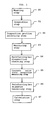
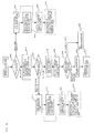
- An inspection method is an inspection method for reinforced concrete pipes for inspecting the deterioration state of a reinforced concrete pipe inside the pipe, which comprises an inspection step for checking the presence or absence of deterioration by carrying out any one or both of a visual examination and impact elastic wave test and classifying the progression level of the deterioration; an inspection portion selecting step for selecting a portion to be inspected in detail in an inspection area based on the inspection result; a measuring step for measuring the pipe thickness and the diameter of reinforcing bars in the selected portion to be inspected in detail; a reinforcing bar disposition checking step for checking the location of the reinforcing bars in the portion to be inspected in detail; and a calculating step for calculating the strength of the reinforced concrete pipe by analyzing the structure using the respective data of the pipe thickness, the diameter of the reinforcing bars and the disposition of the reinforcing bars obtained in those two steps, wherein the calculation result obtained in the calculating step is used as the information for evaluating the deterioration state of the reinforced concrete pipe.
- the inspection operation time can be reduced. Further, the progression level of the deterioration in the portion to be inspected in detail can be evaluated based on the strength of the pipe in a quantitative manner.
- the inspection method according to the present invention may be adapted so that, in addition to the pipe thickness and the diameter of the reinforcing bars, the depth of cracks is measured in the measuring process.
- step for determining the deteriorated portion (position of cracks) and the step for measuring the strength of concrete may be added.
- the inspection method of the present invention it is preferred to carry out the measurement of the pipe thickness to be inspected, the determination of the deteriorated portion and the measurement of the depth of cracks using an elastic wave transmitter and receiver.
- the inspection method according to the present invention is an inspection method for reinforced concrete pipes for inspecting the deterioration state of a reinforced concrete pipe inside the pipe, which comprises the steps of: measuring propagation waves of a pipe to be inspected by carrying out an impact elastic wave test; analyzing the resonant frequency spectrum of the propagation waves; and determining the deterioration level based on the area ratio between an area of a high frequency component and an area of a low frequency component in the resonant frequency spectrum.
- the inspection method according to the present invention is an inspection method for reinforced concrete pipes for inspecting the deterioration state of a reinforced concrete pipe inside the pipe, which comprises the steps of: measuring propagation waves of a pipe to be inspected by carrying out an impact elastic wave test; analyzing the resonant frequency spectrum of the propagation waves; and determining the deterioration level based on the strength ratio between the top peak strength in the high frequency range(for example, frequency range of 4 to 10kHz) and the top peak strength in the low frequency range(for example, frequency range 3 to 4kHz) in the resonant frequency spectrum.
- the inspection method according to the present invention is an inspection method for reinforced concrete pipes for inspecting the deterioration state of a reinforced concrete pipe inside the pipe, which comprises the steps of measuring propagation waves of a pipe to be inspected by carrying out an impact elastic wave test; and determining the deterioration level based on the changes in the maximum amplitude value of the propagation waves.
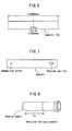
- maximum amplitude value of the propagation wave in the present invention means the magnitude at which the absolute value in the waveform data of the propagation waves reaches the maximum value as shown in Fig. 16.
- the deterioration level of a reinforced concrete pipe constituting a sewage conduit, irrigation conduit or the like can be determined in a quantitative manner.
- the inspection method according to the present invention is an inspection method for reinforced concrete pipes for inspecting the deterioration state of a reinforced concrete pipe inside the pipe, which comprises the steps of: measuring propagation waves by carrying out an impact elastic wave test; obtaining changes of maximum magnitude in the propagation waves; calculating the area ratio between the area of the high frequency component and the area of the low frequency component in the resonant frequency spectrum by analyzing the resonant frequency spectrum of the propagation waves; and determining the classification of deterioration phenomenon and the deterioration progress level by combining the changes of maximum amplitude value in the propagation waves and the area ratio in the resonant frequency spectrum.
- the inspection method of the invention may be arranged so that a step for calculating the strength ratio between the top peak strength in a high frequency range and the top peak strength in a low frequency range of the resonant frequency spectrum is added, and the determination is carried out while adding the top peak strength ratio to the determination criteria.
- a step for calculating the changes in decay time of the propagation waves, and the determination is carried out while adding the changes in decay time to the determination criteria.
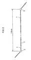
- the inspection method according to the present invention is an inspection method for reinforced concrete pipes for inspecting the deterioration state of a reinforced concrete pipe inside the pipe by means of an impact elastic wave test, wherein the impact elastic wave test is carried out in a state that the distance between the elastic wave injecting position and the elastic wave receiving position is 1/4 or more of the length of the pipe to be inspected away from each other.
- the reason why the disposition distance is prescribed is to clearly detect the changes of the vibration mode. That is, when the distance between the elastic wave injecting position and the receiving position is shorter than 1/4 of the length of the pipe, the vibrations in the area adjacent to the transmitter are detected too strongly. And such a problem arises that the changes of the vibration mode due to the deterioration in a portion far away from the elastic wave injecting position and the elastic wave receiving position is received unclearly.
- the distance between the elastic wave injecting position and the receiving position is 1/4 or more of the length of the pipe. More preferably, the distance is 1/3 or more of the length of the pipe.
- the inspection method according to the present invention is an inspection method for reinforced concrete pipes for inspecting the deterioration state of a reinforced concrete pipe inside the pipe by means of an impact elastic wave test, wherein the impact elastic wave test is carried out by using any one of a receiver of which the configuration of the front end is a cone-like shape or needle-like shape, a receiver of which the front end surface is a flat surface and the area of the front end surface is 3cm 2 or less, or a receiver of which the front end surface is a curved surface and the curvature radius of the front end surface is 25mm or less as the receiver of the elastic waves.
- the receiver by controlling the configuration of the receiver, receiving failure of the impact elastic waves (propagation waves) due to a contact failure between the receiver and the pipe inner surface caused from adhered layers, decayed layers on the inner surface layer of the reinforced concrete pipe constituting the sewage conduit, irrigation conduit or the like, or unevenness of the surface due to exposed reinforcing bars caused from abrasion, can be eliminated. Accordingly, the accuracy of the test can be prevented from degrading.
- An inspection apparatus is an inspection apparatus for reinforced concrete pipes used for inspecting the deterioration state of a reinforced concrete pipe inside the pipe by means of an impact elastic wave test, which comprises: a trolley mounted with a hammering unit; a trolley mounted with a receiving unit; and a joint member for connecting the two trolleys at a specific distance.
- the inspection apparatus may be adapted so as to determine an elastic wave injecting position and elastic wave receiving position by using a trolley mounted with a TV camera.
- the extraneous matter is to be removed by means of cutting using a cutting machine or a water jet washing.
- Corrosion abrasion, cracks, breakage, leakage of water or the like, which are recognizable on the inner surface of the pipe, are checked.
- the inspection method when the diameter of the pipe to be inspected is large enough, an inspector carries out the inspection by the naked eye. When the diameter is too small for the inspector person (criterion: ⁇ 800mm), a TV camera is placed into the pipe to carry out the inspection.
- haming is carried out on the inner surface at an end portion of the pipe to be inspected using a hammer, a steel ball or an impulse hammer.
- Propagated waves are detected with an acceleration sensor or a microphone placed on the inner surface at the other end portion of the pipe to be inspected.
- Speed, decay time, magnitude, resonant frequency, phase and the like of the propagated waves are calculated and compared with a perfectly sound item to check for existing deterioration.
- the hammering In the impact elastic wave test, it is preferred to apply the hammering with the same force on a constant basis.
- a method in which a steel ball or the like is released using a Schmitt hammer or a spring; or, a method, in which a steel ball or the like is dropped from a specific height, is employed.
- a method in which hammering force of an impulse hammer is measured beforehand in order to take into consideration the influence of the hammering force at data analysis, may be employed.
- the impact elastic wave test may be carried out only in an area other than the area where it can be determined as obviously being deteriorated by the appearance test.
- both tests of the appearance test by visual check (TV camera) and the impact elastic wave test may be carried out in the entire area. That is, by carrying out the impact elastic wave test, based on the test result, the progression level of deterioration in the component segment constituting area to be inspected can be classified.
- step S1 when it is determined that the inspected pipe is difficult to be used, the following steps S2 to S7 may be omitted. And the reinforced concrete pipe may be replaced with a new one immediately.
- Portion to be inspected in detail is selected based on the inspection result of the inspection in step S1.
- the criterion of the selection from the following criteria may be employed; i.e., (1) a portion where the deterioration has most progressed; (2) a portion where the progress level of the deterioration is intermediate; (3) a portion where no deterioration is found; and (4) a combination of (1) and (2) above.
- Measurement of pipe thickness to be inspected, determination of deteriorated portion (position of cracks) and measurement of depth of cracks are carried out.
- elastic waves of 20kHz to 1MHz are injected from an injecting device into the pipe to be inspected, and the propagated waves are detected and measured by a receiving unit.
- the frequency of the elastic wave is 20kHz or less, quantitative measurement is impossible; and when it is higher than 1MHz, a large diffusion results and the analysis is difficult.
- a transmitter (vibrator) employing a piezoelectric element is preferably used.
- a receiver employing a piezoelectric element is preferably used.
- the pipe thickness is measured.
- a transmitting/receiving sensor in which a transmitter and a receiver are integrated, is preferably used.
- Receivers are disposed at a plurality of points on the pipe to be inspected, and the propagation time from the transmitter to each receiver is measured to determine deteriorated portions.
- the depth of cracks in the determined deteriorated portion is measured using, for example, a method set forth in "Concrete Diagnosis Technique 1) 1 [Basic] 4.4.2 (5)(a)(c);” or a technique disclosed in Japanese Published Examined Patent Application No. H6-52259.
- the disposition of reinforcing bars is checked using an electromagnetic induction type inspection machine or an electromagnetic wave type inspection machine, which are generally available from the market.
- an X-ray type is also available.
- the pipe wall has to be transmitted, it is difficult to apply the X-ray type inspection machine to the existing concrete pipes.
- the disposition of reinforcing bars in the drawings may be used as the data, and the checking step of the disposition of reinforcing bars using an inspection machine may be omitted accordingly.
- Strength of concrete is measured by means of a compressive strength test using a common core sampling, a needle insertion test (Japanese Published Unexamined Patent Application No. H10-090150) using a small diameter core or a strength test using a Schmitt hammer and the like.
- the progression level of neutralization of the reinforcing bars may be measured using an indicator such as phenolphthalein.
- Core sampling is carried out, and when a reinforcing bar is included, the diameter of the reinforcing bar is measured directly.
- the following method may be employed. That is, a part of the concrete is broken off; using a self-potential method for detecting the corrosion level of the reinforcing bar based on the potential difference between the exposed reinforcing bar and the surface of the concrete, the relationship between the reinforcing bar corrosion level and the diameter of the reinforcing bar is calculated beforehand; and the diameter of the reinforcing bar is calculated based on the corrosion level of an object.
- breaking off using an indicator such as phenolphthalein, the progression level of neutralization of the reinforcing bar may be measured.
- the diameter reinforcing bar measuring step S6 may be omitted.
- a load-stress curve as shown in Fig. 5 is created.
- reading the breaking criterion of the concrete as 4.9MPa (0.5kg/mm 2 ) the breaking load was obtained.
- the above-described structural analysis is carried out on the pipe to be inspected (reinforced concrete pipe) to obtain the breaking load.
- the data used for structural analysis for the thickness of pipe (B) , the data, which are measured in measuring step S3, are used; and for the diameter of the reinforcing bar (straight reinforcing bar) (C) , the data, which are measured in diameter reinforcing bar measuring step S6, are used.
- the pitch of reinforcing bar (D) the cage diameter of reinforcing bar (E) and the depth to reinforcing bar (F)
- the data which are calculated based on the disposition of the reinforcing bars checked in reinforcing bar disposition checking step S4, are used.
- the breaking load of the pipe to be inspected which was obtained by the above-described structural analysis and calculation, and by obtaining the scale of the breaking load with respect to the designed load, the deterioration state of the pipe to be inspected can be evaluated in a quantitative manner.
- the classification of the deterioration level is evaluated in a quantitative manner. Accordingly, based on the strength of the pipe in a portion to be inspected in detail, the strength of the pipe in each of the component segments can be can be estimated.
- Structural calculation software for carrying out the above-described structural analysis is available on the market. It is preferable to use software to carry out the above steps efficiently.
- the deterioration state of the pipe to be inspected may be determined comprehensively.
- classification of the deterioration of the reinforced concrete pipe can be determined quantitatively.
- a hammering tool such as a hammer, a steel ball or an impulse hammer is available.
- a method in which the steel ball or the like is released with a specific force using a Schmitt hammer or spring; or a method, in which the steel ball or the like is dropped from a specific height, is employed.
- a method in which the hammering force of the impulse hammer is measured beforehand to take the influence of the hammering force into consideration during the data analysis, may be employed.
- an acceleration sensor As for the receiver, an acceleration sensor, an AE sensor and vibration sensor or the like is available.
- the receiver may be fixed using an adhesive tape or agent, or may be brought into contact with the object by hand, a holding tool or the like.
- the injecting device and receiver may come into contact with water, acid water or basic water. Accordingly, the injecting device and receiver are preferably constituted with a material such as SUS, which is superior in anti-corrosion.
- the propagated waves are detected by the receiver, which is set on the inner surface at other end portion of the pipe to be inspected, and the waveform data is stored in the recording unit.
- the distance between the elastic wave injecting position by the injecting device and the elastic wave receiving position by the receiver is 1/4 or more of the length of the pipe to be inspected away from each other.
- a resonant frequency spectrum chart is created (refer to Fig. 11). Then, integration processing is made on the created resonant frequency spectrum chart, and a high frequency component and low frequency component are obtained. And thus, the area ratio between the area of the high frequency component and the area of the low frequency component is calculated.
- the resonant frequency spectrum by dividing with 4kHz as the boundary, area ratios between the range of 0 to 4kHz and the range of 4 to 8kHz are obtained, and the deterioration level of the pipe to be inspected is determined based on the area ratio.
- the boundary value (for example 4kHz) between the high frequency and the low frequency may be preset. It is preferred to make a determination at the measuring site depending on the type of the pipe to be inspected for facilitating the determination.
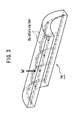
- the injecting device and the receiving unit are disposed at the positions shown in Fig. 9, and injection of elastic waves and reception of propagation waves were performed.
- the deterioration level of the pipe to be inspected can be determined quantitatively.
- a hammering tool such as a hammer, a steel ball or an impulse hammer is available.
- a method in which the steel ball or the like is released with a specific force using a Schmitt hammer or spring, or a method, in which the steel ball or the like is dropped from a specific height, is employed.
- a method in which the hammering force of the impulse hammer is measured beforehand to take the influence of the hammering force into consideration during the data analysis, may be employed.
- an acceleration sensor As for the receiver, an acceleration sensor, an AE sensor and vibration sensor or the like is available.
- the receiver may be fixed using an adhesive tape or agent, or may be brought into contact with the object by hand, a holding tool or the like.
- the injecting device and receiver may come into contact with water, acid water or basic water. Accordingly, the injecting device and receiver are preferably constituted of a material such as SUS, which is superior in anti-corrosion.
- the distance between the elastic wave injecting position by the injecting device and the elastic wave receiving position by the receiver is 1/4 or more of the length of the pipe to be inspected away from each other.
- a resonant frequency spectrum chart is created (refer to Fig. 15). Then, the strength ratio between the top peak strength in the frequency range of 4 to 10kHz (high frequency range) and the top peak strength in the frequency range of 3 to 4kHz (low frequency range) of the created resonant frequency spectrum is calculated. And based on the calculated top peak strength ratio, the deterioration level of the pipe to be inspected is determined.
- the injecting device and the receiving unit were disposed at the position shown in Fig. 9, and the injection of elastic waves and reception of the propagated waves were carried out.
- the ratio (P1/P2) of the top peak strength (P1) in the frequency range of 4 to 10kHz with respect to the top peak strength (P2) in the frequency range in 3 to 4kHz becomes larger. Accordingly, by obtaining the ratio between the top peak strength in the frequency range of 4 to 10kHz and the top peak strength in the frequency range of 3 to 4kHz in the resonant frequency spectrum of the propagation waves, based on the strength ratio, the deterioration level of the pipe to be inspected can be determined quantitatively.
- a hammering tool such as a hammer, a steel ball or an impulse hammer is available.
- a method in which the steel ball or the like is released with a specific force using a Schmitt hammer or a spring, or a method, in which the steel ball or the like is dropped from a specific height is employed.
- a method in which hammering force of the impulse hammer is measured beforehand to take the influence of the hammering force into consideration during the data analysis, may be employed.
- an acceleration sensor As for the receiver, an acceleration sensor, an AE sensor and vibration sensor or the like is available.
- the receiver may be fixed using an adhesive tape or agent, or may be brought into contact with the object by hand, a holding tool or the like.
- the injecting device and receiver may come into contact with water, acid water or basic water. Accordingly, the injecting device and receiver are preferably constituted of a material such as SUS, which is superior in anti-corrosion.
- the distance between the elastic wave injecting position by the injecting device and the elastic wave receiving position by the receiver is 1/4 or more of the length of the pipe to be inspected away from each other.
- the "maximum amplitude value of the propagation wave” is defined as a maximum amplitude value at which the absolute value is the maximum in the waveform data of the propagation waves as shown in Fig. 16.
- the injecting device and the receiving unit are disposed at positions shown in Fig. 9, injection of elastic waves and reception of propagation waves were carried out.
- the maximum amplitude value of the propagation waves becomes smaller. Accordingly, by obtaining the maximum amplitude value of the propagation waves from the waveform data, based on the maximum amplitude value, the deterioration level of the pipe to be inspected can be determined quantitatively.
- the classification of deterioration phenomenon and deterioration progression level can be determined based on Table 8.
- the wording "decay time of propagation waves” means a period of time when the amplitude value of the propagation waves (received waves) becomes a certain value or less as shown in Fig. 17.
- the waves up to the first point are “input waves;” and the period of time up to the first point is “decay time.”
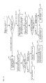
- Step S101 Analysis of changes in the decay time of the propagation waves. When no change is found in the decay time, the process proceeds to step S102. When a change is found in the decay time, the process proceeds to step S111. The analysis of the change in the decay time is made by comparison with a perfectly sound item.
- Step S102 When no change is found in the decay time of the propagation waves, the item is recognized as "no deterioration,” or, either or both of “item with peripheral crack” and/or “item with reduced pipe thickness” are possible (refer to Table 8).
- Step S103 Analysis of the maximum amplitude value of the propagation waves. When no change is found in the maximum amplitude value, the process proceeds to step S104. When a change is found in the maximum amplitude value, the process proceeds to step S131. The analysis of the changes of maximum amplitude value is made by comparison with a perfectly sound item.
- Step S104 When no change is found in the decay time or the maximum amplitude value of the propagation waves, the item is recognized as "no deterioration” or “item with reduced pipe thickness” (refer to Table 8).
- Step S105 Resonant frequency spectrum chart (refer to Fig. 11) is created using the FFT.
- Step S106 Analysis of the area ratio between the low frequency range and the high frequency range in the resonant frequency spectrum (for a detailed analysis process, refer to the above-described Embodiment 2).
- the item is determined as "item with reduced pipe thickness" (step S107) .
- the deterioration level is determined (step S108).
- the item is determined as "no deterioration" (step S109).
- Step S111 In the analysis in step S101, when a change is found in decay time (reduction) , the item is recognized as "item generated with axial crack.”
- determination process of the deterioration level is carried out by means of maximum magnitude value analysis (step S112).
- a resonant frequency spectrum chart (refer to Fig. 11) is created using the process in steps S121 and S122; i.e., FFT. Then, the area ratio between the low frequency range and the high frequency range of the resonant frequency spectrum was obtained. Based on the area ratio, processing to determine the deterioration level is carried out.
- Step S131 When a change is found in the amplitude value (reduction) in the analysis in step S103, the item is recognized as "item generated with peripheral crack.”
- the deterioration level is determined by means of maximum magnitude value analysis (step S132). Or, a resonant frequency spectrum chart (refer to Fig. 15) is created using the process in steps S141 and S142; i.e., FFT. Then, the top peak strength ratio between the frequency range of 4 to 10kHz and the frequency range of 3 to 4kHz in the resonant frequency spectrum of the propagation waves is analyzed (for a detailed analysis process, refer to Embodiment 3). Based on the strength ratio, the deterioration level is determined.
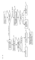
- Step S201 Analysis of the changes in the decay time of the propagation waves. When no change is found in the decay time, the process proceeds to step S202. When a change is found in the decay time, the process proceeds to step S211. The analysis of changes in the decay time is made by comparison with a perfectly sound item.
- Step S202 When no change is found in the decay time of the propagation waves, the item is recognized as "no deterioration,” or either or both of “item generated with peripheral crack” and/or “item with reduced pipe thickness” (refer to Table 8).
- Step S203 Resonant frequency spectrum chart is created using the FFT (refer to Fig. 11).
- Step S204 Analysis of the area ratio between the low frequency range and the high frequency range in the resonant frequency spectrum (for a detailed analysis process, refer to Embodiment 2).
- the item is determined as "item with reduced pipe thickness" (step S205).
- the deterioration level is determined (step S206).
- the process proceeds to step S231.
- Step S211 In the analysis in step S201, when a change is found in the decay time (reduction) , the item is recognized as "item generated with axial crack.”
- the deterioration level is determined by means of maximum magnitude value analysis (step S212). Or, a resonant frequency spectrum chart (refer to Fig. 11) is created using the processing of steps S213 and S214; i.e., FFT. Then, the area ratio between the low frequency range and the high frequency range in the resonant frequency spectrum is analyzed. Based on the area ratio, processing to determine the deterioration level is carried out.
- Step S231 In the analysis in step S204, when no change is found in the area ratio, the item is recognized as "no deterioration” or “item generated with peripheral crack” (refer to Table 8).
- Step 5232 The maximum amplitude value in the propagation waves is analyzed, and when no change is found in the maximum amplitude value, the item is recognized as "no deterioration. " On the other hand, when a change is found in the maximum amplitude value (reduction in amplitude) , the item is recognized as "item generated with peripheral crack" (step S233). When the pipe to be inspected is recognized as “item generated with peripheral crack,” processing to determine the deterioration level is carried out (step S234) by means of maximum magnitude value analysis. Or, processing steps from S241 to S244 are carried out. The analysis of changes in the maximum amplitude value is made by comparison with a perfectly sound item.
- the resonant frequency spectrum chart (refer to Fig. 15) is created using the FFT.
- the top peak strength ratio between the frequency range of 4 to 10kHz and the frequency range of 3 to 4kHz in the resonant frequency spectrum is analyzed (for a detailed analysis process, refer to the above-described Embodiment 3).
- ratio increase when a change is found in the top peak strength ratio (ratio increase) , the item is recognized as "item generated with peripheral crack.” Then, based on the strength ratio, the deterioration level is determined. When no change is found in the top peak strength ratio in the analysis in step S242, the item is determined as "no deterioration.”
- Step S301 Analysis of the maximum amplitude value of the propagation waves.
- a change reduction in amplitude
- the process proceeds to step S302.
- no change is found in the maximum amplitude value
- the process proceeds to step S321.
- the analysis of changes in the maximum amplitude value is made by comparison with a perfectly sound item.
- Step S302 When a change is found in the maximum amplitude value of the propagation waves, the item is recognized as either or both of "item generated with axial crack” and/or “item generated with peripheral crack” (refer to Table 8).
- Step S303 Analysis of changes in the decay time of the propagation waves.
- the process proceeds to step S331.
- the analysis of changes in the decay time is made by comparison with a perfectly sound item.
- the item is recognized as "item generated with peripheral crack" (step S304).
- the deterioration level is determined by means of maximum magnitude value analysis (step S305). Or, a resonant frequency spectrum chart (refer to Fig. 15) is created using the process in steps S315 and S316; i.e., FFT. Then, the top peak strength ratio between the frequency range of 4 to 10kHz and the frequency range of 3 to 4kHz in the resonant frequency spectrum of the propagation waves is analyzed (for a detailed analysis process, refer to the above Embodiment 3). Based on the strength ratio, a processing to determine the deterioration level is carried out.
- Step S321 In the analysis in step S301, when no change is found in the amplitude value, the item is recognized as "no deterioration" or “item with reduced pipe thickness” (refer to Table 8) .
- Step S322 A resonant frequency spectrum chart is created using the FFT (refer to Fig. 11).
- Step S323 The area ratio between the low frequency range and the high frequency range in the resonant frequency spectrum is analyzed (for a detailed analysis process, refer to the above Embodiment 2).
- a change increase of low frequency component
- the item is determined as "item with reduced pipe thickness" (step S324).
- the deterioration level is determined (step S325).
- the item is determined as "no deterioration" (step S326).
- Step S331 In the analysis in step S303, when a change is found in the decay time (reduction) , the item is recognized as "item generated with axial crack.”
- the deterioration level is determined by means of maximum magnitude value analysis (step S332).
- a resonant frequency spectrum chart (refer to Fig. 11) is created using the processing in steps S341 and S342; i.e., FFT. Then, the area ratio between the low frequency range and the high frequency range in the resonant frequency spectrum is calculated. Based on the area ratio, processing to determine the deterioration level is carried out.
- Step S401 Analysis of the maximum amplitude value in the propagation waves.
- a change reduction in amplitude
- the process proceeds to step 5402.
- no change is found in the maximum amplitude value
- the process proceeds to step S411.
- the analysis of changes in the maximum amplitude value is made by comparison with a perfectly sound item.
- Step S402 When a change is found in the maximum amplitude value of the propagation waves, the deterioration level is classified based on the reduced amount of the maximum amplitude value.
- the item When a change is found in the decay time and the maximum amplitude value of the propagation waves, the item is recognized as either or both of "item generated with axial crack” and “item generated with peripheral crack” (refer to Table 8).
- Step S403 A resonant frequency spectrum chart (refer to Fig. 11) is created using FFT.
- Step S404 The area ratio between the low frequency range and the high frequency range in the resonant frequency spectrum is analyzed (for analysis process, refer to the above Embodiment 2).
- a change increase of low frequency component
- the item is determined as "item generated with axial crack” (step S405).
- the item is determined as "item generated with peripheral crack” (step S406).
- Step S411 In the analysis in step S401, when no change is found in the amplitude value, the item is recognized as "no deterioration” or “item with reduced pipe thickness” (refer to Table 8).
- Step S412 A resonant frequency spectrum chart (refer to Fig. 11) is created using the FFT.
- Step S413 The area ratio between the low frequency range and the high frequency range in the resonant frequency spectrum is analyzed (for a detailed analysis process, refer to Embodiment 2).
- a change increase of low frequency component
- the item is determined as "item with reduced pipe thickness" (step S414).
- the deterioration level is determined (step S415).
- the item is determined as "no deterioration" (step S416) .
- Step S501 Analysis of the maximum amplitude value in the propagation waves.
- a change reduction in amplitude
- the process proceeds to step S502.
- no change is found in the maximum amplitude value
- the process proceeds to step S511.
- the analysis of the change in maximum amplitude value is made by comparison with a perfectly sound item.
- Step S502 When a change is found in the maximum amplitude value of the propagation waves, the deterioration level is classified based on the reduced amount of the maximum amplitude value.
- the item When a change is found in the decay time and the maximum amplitude value of the propagation waves, the item is recognized as either or both of "item generated with axial crack” or “item generated with peripheral crack” (refer to Table 8).
- Step S503 Analysis of change in the decay time of the propagation waves.
- the item is determined as "item generated with axial crack” (step S504).
- the item is determined as "item generated with peripheral crack” (step S505).
- Step S511 In the analysis in step S501, when no change is found in the amplitude value, the item is recognized as either or both of "no deterioration" or “item with reduced pipe thickness” (refer to Table 8).
- Step S512 A resonant frequency spectrum chart (refer to Fig. 11) is created using the FFT.
- Step S513 Analysis of area ratio between the low frequency range and the high frequency range in the resonant frequency spectrum (for analysis processing, refer to the above Embodiment 2).
- the item is determined as "item with reduced pipe thickness" (step S514).
- the deterioration level is determined based on the area ratio (step S515).
- the item is determined as "no deterioration" (step S516).
- the injecting device and the receiving unit are disposed at the positions shown in Fig. 9, and injection of elastic waves and reception of propagation waves were performed.
- the resonant frequency spectrum was analyzed using an FFT analyzing program (manufactured by APTEC). Then, with respect to each of the respective resonant frequency spectrums, by dividing with 4kHz as the boundary, the area ratio between the range of 0 to 4kHz and the range of 4 to 8kHz was obtained by Igor Pro (manufactured by Wave Metrics). The results are shown in Fig. 23.
- the resonant frequency spectrum was analyzed using the FFT function. Then, with respect to each of the resonant frequency spectrums, by dividing with 4kHz as the boundary, the area ratio between the range of 0 to 4kHz and the range of 4 to 8kHz was obtained by Igor Pro (manufactured by Wave Metrics).
- the progress level of the axial cracks can be determined.
- top peak strength in the frequency range of 4 to 10kHz (high frequency range) and the top peak strength in the frequency range of 3 to 4kHz were obtained.
- the strength ratio between the top peak strength in the frequency range of 4 to 10kHz and the top peak strength of the frequency range (low frequency range) of 3 to 4kHz was calculated.
- the strength ratio in the sample T54 was 1.40; and the strength ratio in the sample T55 was 1.64.
- the progress level of the peripheral cracks can be determined. As described above, using the maximum amplitude value, the progress level can be determined.
- the injecting device and receiver used in the impact elastic wave test will be described first.
- a hammering tool such as a hammer, a steel ball or an impulse hammer is available.
- a method in which the steel ball or the like is released with a specific force using a Schmitt hammer or a spring, or a method, in which the steel ball or the like is dropped from a specific height, is employed.
- a method in which hammering force of the impulse hammer is measured beforehand to take the influence of the hammering force into consideration during the data analysis, may be employed.
- an acceleration sensor As for the receiver, an acceleration sensor, an AE sensor, vibration sensor or the like is available.
- the receiver may be fixed using an adhesive tape or agent, or may be brought into contact with the obj ect by hand, a holding tool or the like.
- the injecting device and receiver may come into contact with water, acid water or basic water. Accordingly, the injecting device and receiver are preferably constituted of a material such as SUS, which is superior in anti-corrosion.
- an impact elastic wave test is carried out. That is, using a hammer, a steel ball or an impulse hammer, hammering is carried out on the inner surface at the end portion of the pipe to be inspected, propagated waves are detected with an acceleration sensor or a microphone set on the inner surface at the other end portion of the pipe to be inspected. Speed, decay time, magnitude, resonant frequency, phase and the like of the propagated wave are obtained. Based on the comparison with the perfectly sound item, the existence of deterioration is checked.
- This embodiment is characterized in that, when reinforced concrete pipe constituting a sewage conduit or irrigation conduit is inspected by means of the impact elastic wave test, the distance between the elastic wave injecting position and the elastic wave receiving position is set being away from each other by 1/4 or more of the length of the pipe to be inspected.
- the injecting device and the receiving unit are disposed at the positions (Example 6-1 to 6-5 and Comparison example 6-1 and 6-2) shown in Fig. 26, and injection of elastic waves and reception of propagation waves were performed.
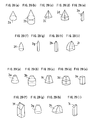
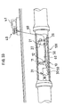
- receivers 2a-2e which have the front end of a cone-like or pyramid-like shape, are available.
- receivers 2f to 2i of which the conical surface (side surface) is formed into a curved surface, may be employed.
- a receiver having a cone-like shape as described above In place of a receiver having a cone-like shape as described above, a receiver of which the front end has a needle-like shape, may be employed.
- receivers 3a to 3i of which the front end surface is a flat-shape, are available.
- the area of the front end surface is 3cm 2 or less, more preferably, 2.5cm 2 or less. If the area of the front-end surface of the receiver is 3cm 2 or more, the receiver fails to stably come into contact with the inner surface of the pipe to be inspected, and accordingly, the stability of the measurement is reduced.
- receivers 4a to 4g of which the front end surface has a curved surface
- the curvature radius of the front end surface is preferably 25mm or less, more preferably, 20mm or less. If the curvature radius of the front end surface of the receiver is 25mm or more, the receiver fails to stably come into contact with the inner surface of the pipe to be inspected, and accordingly, the stability of the measurement is reduced.
- the receiver may be fixed with an adhesive tape, agent or the like.
- the receiver may be held by hand, a holding tool or the like.
- the receiver since the receiver may come into contact with water, acid water or basic water, the receiver is preferably made of a material such as SUS, which is superior in anti-corrosion.
- the injecting device and the receiving unit were disposed at the positions shown in Fig. 9, and injection of the elastic waves and the reception of the propagation waves were carried out.
- FIG. 33 an embodiment of an inspection apparatus for reinforced concrete pipes according to the present invention will be described.
- An inspection apparatus shown in Fig. 33 comprises a hammering unit trolley 10, a receiving unit trolley 20, a TV camera trolley 30 and a data recording unit 40.
- the hammering unit trolley 10, the receiving unit trolley 20 and the TV camera trolley 30 are capable of traveling inside a Hume pipe 100, which is a pipe to be inspected.
- the data-recording unit 40 is disposed above ground within an area to be inspected.
- the hammering unit trolley 10 and the receiving unit trolley 20 are connected to each other with a joint member 50, and it is arranged so that influence due to vibration generated from the hammering unit trolley 10 at hammering is not rendered to the receiving unit trolley 20 side.
- the inspection apparatus and the joint 50 are made of materials such as stainless steel and aluminum alloy, which hardly accumulate rust, and are provided with waterproofing characteristic.
- the connecting method between the joint member 50 and the hammering unit trolley 10 and the receiving unit trolley 20 for example, the following method may be employed. That is, a connecting female screw (not shown) is provided to each of the trolleys 10 and 20, and on the both ends of the joint member 50, a male screw (not shown) , which is coupled with the connecting female screw on each of the trolleys 10 and 20 is prepared respectively, and the male screw at the end portion of the joint member 50 is screwed into the connecting female screw on each of the trolleys 10 and 20 to connect to each other.
- an eye bolt is provided to each of the trolleys 10 and 20
- a hook is provided to the both end portions of the joint member 50, and each of the hooks are hooked to each of the eye bolts on the trolleys 10 and 20 to connect to each other.
- the joint member 50 is made of, for example, a material such as metal or resin, which hardly expands and contracts.
- the hammering unit trolley 10 and the receiving unit trolley 20 are connected to each other via an electric cable 60 for data transfer. Also, the receiving unit trolley 20 is connected to the data-recording unit 40 above ground via the electric cable for data transfer 60.
- an injecting device 11 of an elastic wave mounted on the hammering unit trolley 10 is an injecting device 11 of an elastic wave.
- the injecting device 11 is disposed on a lifting mechanism 12, which is provided with a driving force by means of electric power or an air cylinder. Being driven by the lifting mechanism 12, the injecting device 11 can be moved to a position where the hammering is possible at measurement. Also, the injecting device 11 can be moved to a position where the injecting device 11 is free from coming into contact with the inner surface of the pipe during traveling.
- a receiving unit 21 for receiving the propagated wave.
- the receiving unit 21 disposed on a lifting mechanism 22 provided with a driving force by means of electric power or air cylinder. Being driven by the lifting mechanism 22, the receiving unit 21 can be raised to a position where the reception is possible at measurement. Also, the receiving unit 21 can be lowered to a position where the receiving unit 21 is free from coming into contact with the inner surface of the pipe during traveling.
- the above-mentioned apparatuses such as injecting device 11 and the receiving unit 21 are securely fixed to each of the trolleys 10 and 20 with bolts or the like.
- a CCD camera 31 mounted on the TV camera trolley 30 is used for determining the elastic wave injecting position by the injecting device 11, the elastic wave receiving position by the receiving unit 21 and the receiving position.
- the image data from the CCD camera 31 are guided to the data-recording unit 40 via an electric cable for data transfer (not shown), and displayed on a screen of a monitor 41.
- the CCD camera 31 is mounted on the TV camera trolley 30, is shown; but it is limited thereto.
- the CCD camera may be mounted on any one or both of the hammering unit trolley 10 and the receiving unit trolley 20. Further, it is preferred to mount a lighting apparatus the same as the CCD camera 31 for facilitating confirmation of the observation point.
- the CCD camera also travels inside the existing conduit. Identical to the above-described inspection apparatuses and the like, a waterproofing characteristic is preferably provided to the CCD camera.
- the traveling means of the hammering unit trolley 10 the receiving unit trolley 20 and the TV camera trolley 30 within the conduit, the following methods are conceivable. That is, the TV camera trolley 30 or the receiving unit trolley 20, which is positioned at the top, is pulled with a wire or the like; or, the TV camera trolley 30 or the receiving unit trolley 20 is arranged so as to be self-driven to travel.
- the distance from the top of the pipe to the hammering point is maintained at a fixed distance to stabilize the hammering force provided to the object to be measured; and thus, to increase the accuracy of the obtained data.
- the lifting mechanism 22 and the receiving unit 21 are mounted in this order on the measuring apparatus main body.
- a control mechanism such as a load cell, which is capable of controlling the contact force of the receiving unit 21, is mounted inside the lifting mechanism 22.
- the inspection apparatus of the embodiment by changing (1) the lifting mechanism, (2) the wheel diameter of the trolleys and/or (3) the size of the trolley, the inspection apparatus of the embodiment can be applied to the inspection of pipes to be inspected each having a different pipe diameter. Further, by adjusting the length of the joint member 50, the inspection apparatus of the embodiment can be applied to the inspection of pipes to be inspected each having a different length of pipe.
- the data-recording unit may be mounted on the hammering unit trolley or the receiving unit trolley.
- the inspection method of the present invention when inspecting the deterioration state of a reinforced concrete pipe constituting a sewage conduit, an irrigation conduit or the like, the progression level of the deterioration in a component segment of an area to be inspected is classified, and a portion to be inspected in detail is selected. Accordingly, the time for inspection work can be reduced. Also, the progression level of the deterioration in the portion to be inspected in detail can be evaluated quantitatively based on the strength of the pipe. Further, since the magnitude of the progression level of deterioration can be evaluated quantitatively, based on the strength of the pipe in the portion to be inspected in detail, the strength of the pipe in each of the component segments can be estimated.
- the inspection method by arranging to carry out the determination using various data of deterioration phenomena such as the area ratio between the high frequency component and the low frequency component in a resonant frequency spectrum of propagation waves, the top peak strength ratio between a frequency range of 4 to 10kHz and a frequency range of 3 to 4kHz in the resonant frequency spectrum of the propagation waves, the maximum amplitude value of the propagation waves and decay time of the propagation waves and the like, the deterioration level of the reinforced concrete pipe constituting the sewage conduit, irrigation conduit and the like can be determined quantitatively.
- the inspection method according to the present invention by carrying out the impact elastic wave test in a state that the distance between the elastic wave injecting position and the elastic wave receiving position is 1/4 or more of the length of the pipe to be inspected away from each other, the changes of vibration mode due to the deterioration can be detected precisely.
- the inspection method according to the present invention by carrying out the impact elastic wave test using a receiver of which the front end is a cone-like shape or needle-like shape, a receiver of which front end surface is flat and the area of the front end surface is 3cm 2 or less, or a receiver of which the front end surface is a curved surface and the curvature radius of the front end surface thereof is 25mm or less as the receiver of the elastic waves, the inspection by means of the impact elastic wave test can be carried out accurately irrespective of the state of the inner surface layer of the pipe to be inspected.
Landscapes
- Physics & Mathematics (AREA)
- General Physics & Mathematics (AREA)
- Health & Medical Sciences (AREA)
- Life Sciences & Earth Sciences (AREA)
- Chemical & Material Sciences (AREA)
- Immunology (AREA)
- Biochemistry (AREA)
- Analytical Chemistry (AREA)
- Pathology (AREA)
- General Health & Medical Sciences (AREA)
- Engineering & Computer Science (AREA)
- Signal Processing (AREA)
- Acoustics & Sound (AREA)
- Food Science & Technology (AREA)
- Medicinal Chemistry (AREA)
- Mathematical Physics (AREA)
- Ceramic Engineering (AREA)
- Spectroscopy & Molecular Physics (AREA)
- Investigating Or Analyzing Materials By The Use Of Ultrasonic Waves (AREA)
Abstract
Description
- Sample T21: Unprocessed product
- Sample T22: item introduced with axial cracks Dropped on concrete surface to generate four cracks in the axial direction
- Sample T23: item introduced with axial cracks Dropped on concrete surface to generate ten cracks in the axial direction (refer to Fig. 10). As for the number of the cracks in the samples T22 and T23, the number of cracks generated on the inner and outer surfaces was checked at one end surface by visual check.
- Sample T24: item of which inner surface was ground. The reinforcing bars were exposed out of the inner surface layer by means of water jet blasting. Amount of grinding was set so as to be 1.6mm in average grinding thickness. The ground amount was measured at ten points on each end in an area adjacent to the pipe end; total 20 points, using a slide caliper.
- Sample T31: Non-processed
- Sample T32: Item introduced with peripheral cracks Item, which is introduced with a crack of 0.15mm in width by means of introduction as shown in Fig. 13 (refer to Fig. 14).
- Sample T33: Item introduced with peripheral cracks Item, which is introduced with a crack of 1.3mm in width by means of introduction as shown in Fig. 13 (refer to Fig. 14). The width of cracks in the samples T32 and T33 were measured while being enlarged by a magnifier with a scale (average of values at 5 points).
- Sample T41: non-processed item
- Sample T42: item introduced with axial cracks Item dropped on a concrete surface and generated with four cracks in the axial direction.
- Sample T43: item introduced with axial cracks Item dropped on concrete surface and generated with ten cracks in the axial direction (refer to Fig. 10). The number of the cracks in the samples T42 and T43, which were generated on the inner and outer surface, was visually checked at one end surface thereof.
- Sample T44: item introduced with peripheral cracks Item generated with cracks with width of 0.15mm in the peripheral direction by means of crack introducing method shown in Fig. 13 (refer to Fig. 14).
- Sample T45: item introduced with peripheral cracks Item generated with cracks with width of 1.3mm in the peripheral direction by means of crack introducing method shown in Fig. 13 (refer to Fig. 14). The width of cracks in the samples T44 and T45 were measured while being enlarged by a magnifier with a scale (average of values at 5 points).
- Sample T51: non-processed item
- Sample T52: item introduced with cracks Item dropped on a concrete surface and generated with four cracks in the axial direction.
- Sample T53: item introduced with cracks Item dropped on concrete surface and generated with ten cracks in the axial direction (refer to Fig. 10). The number of the cracks in the samples T52 and T53, which were generated on the inner and outer surface, was visually checked at the one end surface thereof.
- Sample T54: item introduced with peripheral cracks Item generated with cracks with width of 0.15mm in the peripheral direction by means of processing of crack introducing method shown in Fig. 13 (refer to Fig. 14).
- Sample T55: item introduced with peripheral cracks Item generated with cracks with width of 1.3mm in the peripheral direction by means of processing of crack introducing method shown in Fig. 13 (refer to Fig. 14).The width of cracks in the samples T54 and T55 were measured while being enlarged by a magnifier with a scale (average of values at 5 points).
- Sample T56: pipe with ground inner surface The reinforcing bars were exposed out of the inner surface layer by means of water jet blasting. Amount of grinding was set so as to be 1.6mm in average grinding thickness. The ground amount was measured at ten points on each end in the area adj acent to the pipe end surface; total 20 points, using a slide caliper.
- Sample T61: non-processed item
- Sample T62: item introduced with axial crack
- Sample with reduced pipe thickness T71: The reinforcing bars were exposed out of the inner surface layer by means of water jet blasting. Amount of grinding was set so as to be 1.6mm in average grinding thickness. The ground amount was measured at ten points on each end surface in an area adjacent to the pipe end; total 20 points, using a slide caliper.
- Sample applied with lard T72: item applied with lard on the inner surface of the pipe. Average thickness of the lard is approximately 1 to 4mm.
| Sample | Resonant frequency | Classification of deterioration |
| T11 | 0.8KHz | 3 |
| T12 | 0.2KHz | 1 |
| T13 | 0.5KHz | 2 |
| Sample T21 | Sample T22 | Sample T23 | Sample T24 |
| Non-processed item | Item introduced with 4 axial cracks | Item introduced with 10 axial cracks | Pipe with ground inner surface |
| Area ratio calculation result of each sample | |||||
| Sample | T21 | | T23 | T24 | |
| 0 to 4KHz | 32% | 47% | 73% | 55% | |
| 4 to 8KHz | 68% | 53% | 27% | 45% |
| Sample T31 | Sample T32 | Sample T33 |
| Non-processed item | Item introduced with peripheral crack: 0.15mm | Item introduced with peripheral crack: 1.3mm |
| Peak strength ratio calculation result | |||
| Sample | T31 | T32 | T33 |
| Peak strength ratio | 0.97 | 1.40 | 1.57 |
| Sample T41 | Sample T42 | Sample T43 | Sample T44 | Sample T45 |
| Non-processed item | Item introduced with 4 axial cracks | Item introduced with 10 axial cracks | Item introduced with peripheral crack: 0.15mm | Item introduced with peripheral crack 1.3mm |
| Maximum amplitude value (output value of receiving unit [v]) of each sample | ||||
| Sample T41 | Sample T42 | Sample T43 | Sample T44 | Sample T45 |
| 14.0 | 10.8 | 7.1 | 11.0 | 8.3 |
| Deterioration phenomena | Pipe with reduced thickness | Peripheral crack | Axial crack |
| Maximum amplitude value | No change | Reduction | Reduction |
| Decay time | No change | No change | Reduction |
| Area ratio between an area of high frequency component and an area of low frequency component | High frequency component is reduced. | No change | High frequency component is reduced. |
| Top peak strength in the frequency range of 4 to 10kHz and top peak strength in the frequency range of 3 to 4kHz | Strength in the low frequency side is small. | Strength in the high frequency side is large. | No change |
| Sample T51 | Sample T52 | Sample T53 | Sample T54 | Sample T55 | Sample T56 |
| Non-processed item | Item introduced with 4 axial cracks | Item introduced with 10 axial cracks | Item introduced with peripheral crack: 0.15mm | Item introduced with peripheral crack 1.3mm | Pipe with ground inner surface |
| Maximum amplitude value (output value of receiving unit [v]) of each sample | |||||
| Sample T51 | Sample T52 | Sample T53 | Sample T54 | Sample T55 | Sample T56 |
| 14.0 | 10.8 | 7.0 | 11.0 | 8.3 | 13.8 |

| (a) Measurement results of sample with reduced pipe thickness | ||||
| Example 7-1 | Example 7-2 | Example 7-3 | Comparison example 7-1 | |
| 1st | 12.83 | 13.03 | 13.13 | 3.81 |
| 2nd | 12.53 | 12.53 | 12.73 | 1.90 |
| 3rd | 12.53 | 12.73 | 12.83 | 12.73 |
| (b) Measurement results of sample applied with lard | ||||
| Example 7-1 | Example 7-2 | Example 7-3 | Comparison example 7-1 | |
| 1st | 12.79 | 12.45 | 12.98 | 12.56 |
| 2nd | 12.56 | 12.78 | 12.78 | 11.79 |
| 3rd | 12.91 | 12.56 | 12.63 | 6.12 |
Claims (16)
- An inspection method for reinforced concrete pipes for inspecting the deterioration state of a reinforced concrete pipe inside the pipe, comprising:an inspection step for checking the presence or absence of the deterioration by carrying out any one or both of visual examination and impact elastic wave test and classifying the progression level of the deterioration;an inspection portion selecting step for selecting a portion to be inspected in detail in an inspection area based on the inspection result;a measuring step for measuring the pipe thickness and the diameter of reinforcing bars in the selected portion to be inspected in detail;a reinforcing bar disposition checking step for checking the location of the reinforcing bars in the portion to be inspected in detail; anda calculating step for calculating the strength of the reinforced concrete pipe by analyzing the structure using the respective data of the pipe thickness, the diameter of the reinforcing bars and the disposition of the reinforcing bar obtained in those two steps, whereinthe calculation result obtained in the calculating step is used as the information for evaluating the deterioration state of the reinforced concrete pipe.
- The inspection method for reinforced concrete pipes according to Claim 1, wherein, in the measuring step, the depth of cracks is measured.
- The inspection method for reinforced concrete pipes according to Claims 1 or 2, further comprising any one or both of the steps for determining a deteriorated portion and step for measuring the strength of the concrete.
- The inspection method for reinforced concrete pipes according to any of Claims 1 to 3, wherein the measurement of pipe thickness, the determination of a deteriorated portion and the measurement of depth of the cracks are carried out by using an elastic wave transmitter and a receiver.
- An inspection method for reinforced concrete pipes for inspecting the deterioration state of a reinforced concrete pipe inside the pipe, comprising the steps of:measuring propagation waves of a pipe to be inspected by carrying out an impact elastic wave test;analyzing the resonant frequency spectrum of the propagation waves; anddetermining the deterioration level based on the area ratio between an area of a high frequency component and an area of a low frequency component in the resonant frequency spectrum.
- An inspection method for reinforced concrete pipes for inspecting the deterioration state of a reinforced concrete pipe inside the pipe, comprising the steps of:measuring propagation waves of a pipe to be inspected by carrying out an impact elastic wave test;analyzing the resonant frequency spectrum of the propagation waves; anddetermining the deterioration level based on the strength ratio between the top peak strength in the high frequency range and the top peak strength in the low frequency range in the resonant frequency spectrum.
- An inspection method for reinforced concrete pipes for inspecting the deterioration state of a reinforced concrete pipe inside the pipe, comprising the steps of
measuring propagation waves of a pipe to be inspected by carrying out an impact elastic wave test; and
determining the deterioration level based on the changes in the maximum amplitude value of the propagation waves. - An inspection method for reinforced concrete pipes for inspecting the deterioration state of a reinforced concrete pipe inside the pipe, comprising the steps of:measuring propagation waves by carrying out an impact elastic wave test;obtaining changes of maximum magnitude in the propagation waves;calculating the area ratio between the area of the high frequency component and the area of the low frequency component in the resonant frequency spectrum by analyzing the resonant frequency spectrum of the propagation waves; anddetermining the classification of deterioration phenomenon and the deterioration progress level by combining the changes of maximum amplitude value in the propagation waves and the area ratio in the resonant frequency spectrum.
- The inspection method for reinforced concrete pipes according to Claim 8, further comprising a step of calculating the strength ratio between the top peak strength of the high frequency range and the top peak strength of the low frequency range in the resonant frequency spectrum, wherein
the determination is carried out by adding the top peak strength ratio to the determination criteria. - The inspection method for reinforced concrete pipes according to Claims 8 or 9, further comprising a step of obtaining the changes in the decay time of the propagation waves, wherein
the determination is carried out by adding the changes in the decay time to the determination criteria. - An inspection method for reinforced concrete pipes for inspecting the deterioration state of a reinforced concrete pipe inside the pipe by means of an impact elastic wave test, wherein the impact elastic wave test is carried out in a state that the distance between the elastic wave injecting position and the elastic wave receiving position is 1/4 or more of the length of the pipe to be inspected away from each other.
- An inspection method for reinforced concrete pipes for inspecting the deterioration state of a reinforced concrete pipe inside the pipe by means of an impact elastic wave test, wherein the impact elastic wave test is carried out by using a receiver of which configuration of the front end is a cone-like shape or needle-like shape as the receiver of the elastic waves.
- An inspection method for reinforced concrete pipes for inspecting the deterioration state of a reinforced concrete pipe inside the pipe by means of an impact elastic wave test, wherein the impact elastic wave test is carried out by using a receiver of which the front end surface is a flat surface and the area of the front end surface is 3cm2 or less as the receiver of the elastic waves.
- An inspection method for reinforced concrete pipes for inspecting the deterioration state of a reinforced concrete pipe inside the pipe by means of an impact elastic wave test, wherein the impact elastic wave test is carried out by using a receiver of which the front end surface is a curved surface and the curvature radius of the front end surface is 25mm or less as the receiver of the elastic waves.
- An inspection apparatus for reinforced concrete pipes used for inspecting the deterioration state of a reinforced concrete pipe inside the pipe by means of an impact elastic wave test, comprising:a trolley mounted with a hammering unit;a trolley mounted with a receiving unit; anda joint member for connecting the two trolleys at a specific distance.
- The inspection apparatus for reinforced concrete pipes according to Claim 15, wherein the inspection apparatus is adapted so as to determine the elastic wave injecting position and elastic wave receiving position by using a trolley mounted with a TV camera.
Applications Claiming Priority (5)
| Application Number | Priority Date | Filing Date | Title |
|---|---|---|---|
| JP2002133022 | 2002-05-08 | ||
| JP2002133022 | 2002-05-08 | ||
| JP2002299179A JP4162967B2 (en) | 2001-10-12 | 2002-10-11 | Inspection method for reinforced concrete pipes |
| JP2002299179 | 2002-10-11 | ||
| PCT/JP2003/004587 WO2003096007A1 (en) | 2002-05-08 | 2003-04-10 | Method and equipment for inspecting reinforced concrete pipe |
Publications (3)
| Publication Number | Publication Date |
|---|---|
| EP1503208A1 true EP1503208A1 (en) | 2005-02-02 |
| EP1503208A4 EP1503208A4 (en) | 2011-09-14 |
| EP1503208B1 EP1503208B1 (en) | 2016-06-15 |
Family
ID=29422375
Family Applications (1)
| Application Number | Title | Priority Date | Filing Date |
|---|---|---|---|
| EP03749987.8A Expired - Lifetime EP1503208B1 (en) | 2002-05-08 | 2003-04-10 | Method and equipment for inspecting reinforced concrete pipe |
Country Status (6)
| Country | Link |
|---|---|
| US (3) | US7360462B2 (en) |
| EP (1) | EP1503208B1 (en) |
| KR (1) | KR100960177B1 (en) |
| AU (1) | AU2003236074B2 (en) |
| CA (1) | CA2486366C (en) |
| WO (1) | WO2003096007A1 (en) |
Cited By (4)
| Publication number | Priority date | Publication date | Assignee | Title |
|---|---|---|---|---|
| EP2938990A4 (en) * | 2012-12-27 | 2016-06-01 | Score Group Plc | Systems and methods for determining a leak rate through an opening using acoustical sensors |
| EP2313766B1 (en) * | 2008-08-05 | 2019-10-09 | Pure Technologies Ltd | Device and method to assess impairment of pipeline wall strength |
| CN113138231A (en) * | 2021-04-13 | 2021-07-20 | 武汉理工大学 | Ultrasonic phased array detection device and method for aero-engine case ring forging |
| CN119534621A (en) * | 2024-11-22 | 2025-02-28 | 中广核检测技术有限公司 | Ultrasonic inspection equipment for inner surface of pipeline |
Families Citing this family (37)
| Publication number | Priority date | Publication date | Assignee | Title |
|---|---|---|---|---|
| JP4515848B2 (en) * | 2004-07-26 | 2010-08-04 | 積水化学工業株式会社 | Inspection method for buried pipes |
| JP2006038597A (en) * | 2004-07-26 | 2006-02-09 | Sekisui Chem Co Ltd | Inspection method for buried pipes |
| CA2575036C (en) * | 2004-07-26 | 2012-12-18 | Sekisui Chemical Co., Ltd. | Buried pipe examining method |
| KR100756892B1 (en) * | 2006-05-26 | 2007-09-07 | 한국해양연구원 | Instrument for testing in-hole seismic wave |
| US8296083B2 (en) | 2007-02-22 | 2012-10-23 | Micro Motion, Inc. | Vibratory pipeline diagnostic system and method |
| KR100946618B1 (en) * | 2007-11-14 | 2010-03-10 | 한국표준과학연구원 | Data calculation device and method for electric striking device of concrete |
| AU2009223322B2 (en) * | 2008-03-14 | 2014-08-14 | Expro Meters, Inc. | Method and apparatus for determining pipewall thickness using one or more ultrasonic sensors |
| US9267636B2 (en) | 2010-05-07 | 2016-02-23 | 1876255 Ontario Limited | Protective liner with wear detection |
| WO2011159403A1 (en) | 2010-06-16 | 2011-12-22 | Mueller International, Llc | Infrastructure monitoring devices, systems, and methods |
| IL210776A (en) * | 2011-01-20 | 2015-10-29 | Israel Polishuk | Method and device for estimating the content of a solid material container |
| US9291520B2 (en) | 2011-08-12 | 2016-03-22 | Mueller International, Llc | Fire hydrant leak detector |
| SG11201503041SA (en) | 2012-10-26 | 2015-05-28 | Mueller Int Llc | Detecting leaks in a fluid distribution system |
| JP6589224B2 (en) | 2014-07-25 | 2019-10-16 | 国立大学法人鳥取大学 | Tube evaluation method, measuring apparatus, and tube evaluation system |
| US9739411B1 (en) * | 2014-08-06 | 2017-08-22 | The United States Of Americas As Represented By The Administrator Of The National Aeronautics And Space Administration | System and method for traversing pipes |
| US9528903B2 (en) | 2014-10-01 | 2016-12-27 | Mueller International, Llc | Piezoelectric vibration sensor for fluid leak detection |
| US10156550B2 (en) * | 2014-11-21 | 2018-12-18 | University Of South Carolina | Non-intrusive methods for the detection and classification of alkali-silica reaction in concrete structures |
| JP6214003B2 (en) * | 2014-12-05 | 2017-10-18 | 日本電信電話株式会社 | Evaluation method of neutralization resistance |
| US20180045687A1 (en) * | 2015-03-24 | 2018-02-15 | Nec Corporation | Defect analysis device, defect analysis system, defect analysis method, and computer readable recording medium |
| US10283857B2 (en) | 2016-02-12 | 2019-05-07 | Mueller International, Llc | Nozzle cap multi-band antenna assembly |
| US10305178B2 (en) | 2016-02-12 | 2019-05-28 | Mueller International, Llc | Nozzle cap multi-band antenna assembly |
| CN108018888B (en) * | 2016-11-01 | 2024-03-26 | 上海勘测设计研究院有限公司 | Device and method for measuring contact state between inner wall of steel pipe pile and core filling concrete of offshore wind farm |
| CN107576470A (en) * | 2017-08-14 | 2018-01-12 | 芜湖博康新材料技术有限公司 | A kind of impact frock of automobile batteries housing |
| US11187682B2 (en) * | 2018-07-25 | 2021-11-30 | SENTRO Technologies USA, LLC | System and method for identifying a type of a sediment in an interior cavity of a hollow cylindrical body |
| US20200064219A1 (en) * | 2018-08-23 | 2020-02-27 | Accenture Global Solutions Limited | Pipeline inspection crawler |
| US10859462B2 (en) | 2018-09-04 | 2020-12-08 | Mueller International, Llc | Hydrant cap leak detector with oriented sensor |
| CN109085243B (en) * | 2018-10-08 | 2024-03-12 | 湖南高速铁路职业技术学院 | Method and device for inspecting metal part damage |
| US11342656B2 (en) | 2018-12-28 | 2022-05-24 | Mueller International, Llc | Nozzle cap encapsulated antenna system |
| US11473993B2 (en) | 2019-05-31 | 2022-10-18 | Mueller International, Llc | Hydrant nozzle cap |
| CN110441394A (en) * | 2019-08-08 | 2019-11-12 | 上海市建筑科学研究院 | Existing external thermal insulation system detection method based on acoustic index |
| WO2021195423A1 (en) * | 2020-03-25 | 2021-09-30 | Fdh Infrastructure Services, Llc | Systems and methods for estimating concrete thickness |
| US11542690B2 (en) | 2020-05-14 | 2023-01-03 | Mueller International, Llc | Hydrant nozzle cap adapter |
| CN111948289B (en) * | 2020-08-24 | 2023-07-21 | 四川升拓检测技术股份有限公司 | Concrete cold joint quality detection method, device and system based on shock elastic waves |
| CN112922345B (en) * | 2021-02-02 | 2022-08-16 | 北京崇建工程有限公司 | Outer wall grouting construction device and method |
| CN112962458B (en) * | 2021-02-04 | 2022-09-20 | 四川省公路规划勘察设计研究院有限公司 | Technical test method for pumping and pouring concrete in main arch tube of concrete-filled steel tube arch bridge |
| CN115078532A (en) * | 2022-05-26 | 2022-09-20 | 浙江工业大学 | Quality impact echo detection device and method for concrete beam plate |
| CN115616078B (en) * | 2022-10-19 | 2024-05-07 | 广西大学 | A method for detecting voids in concrete-filled steel tubes based on acoustic vibration characteristics |
| US12578245B2 (en) | 2022-10-28 | 2026-03-17 | Mueller International, Llc | Self-leveling sensor assembly |
Family Cites Families (45)
| Publication number | Priority date | Publication date | Assignee | Title |
|---|---|---|---|---|
| US3302453A (en) * | 1963-04-15 | 1967-02-07 | American Mach & Foundry | Method of inspection utilizing ultrasonic energy |
| US3993974A (en) * | 1974-06-03 | 1976-11-23 | Senturion Sciences, Inc. | Seismic method for determining the position of the bit on a drill stem in a deep borehole |
| FR2359411A1 (en) * | 1976-07-20 | 1978-02-17 | Oreal | APPARATUS FOR MEASURING THE MECHANICAL CHARACTERISTICS OF A MATERIAL SUCH AS SKIN |
| US4170067A (en) * | 1976-10-18 | 1979-10-09 | Bethlehem Steel Corporation | Apparatus for measuring pipe length |
| FR2417762A1 (en) * | 1978-02-16 | 1979-09-14 | Anvar | METHOD AND DEVICES FOR MEASURING THE FATIGUE OF A SPECIMEN SUBJECT TO MECHANICAL STRAINING |
| US4342229A (en) * | 1980-08-25 | 1982-08-03 | The Stoneleigh Trust | Apparatus and method for the non-destructive testing of the physical integrity of a structural part |
| JPS57175952A (en) * | 1981-04-24 | 1982-10-29 | Kyoei Giken:Kk | Non-destructive test device of non-metallic object by impulsive elastic wave |
| JPS5883258A (en) * | 1981-11-13 | 1983-05-19 | Hitachi Zosen Hihakai Kensa Kk | Detection for condition of rear surface of concrete wall |
| JPS5928656A (en) * | 1982-08-11 | 1984-02-15 | Hitachi Ltd | Detector of foreign matter |
| DE3380939D1 (en) * | 1982-10-06 | 1990-01-11 | Welding Inst | ACOUSTIC DETECTING DEFECTS IN STRUCTURES. |
| JPS60207013A (en) * | 1984-03-31 | 1985-10-18 | Toshiba Corp | Method and apparatus for measuring looseness |
| GB8420244D0 (en) * | 1984-08-09 | 1984-09-12 | Shell Int Research | Transducing device |
| JPS626194A (en) | 1985-07-02 | 1987-01-13 | 動力炉・核燃料開発事業団 | Fuel aggregate for nuclear reactor |
| JPH0679016B2 (en) * | 1985-07-03 | 1994-10-05 | 株式会社日立製作所 | Method and apparatus for ultrasonic inspection of concave corners |
| JPS6234360A (en) | 1985-08-08 | 1987-02-14 | Pioneer Electronic Corp | Multidisk player |
| JPS6234360U (en) * | 1985-08-16 | 1987-02-28 | ||
| JPS6298287A (en) | 1985-10-24 | 1987-05-07 | Shimadzu Corp | metal detection device |
| US4702111A (en) * | 1986-04-01 | 1987-10-27 | American Energy Services, Inc. | Sonic wood testing apparatus and method |
| US5048320A (en) * | 1986-08-28 | 1991-09-17 | Mitsui Engineering & Shipbuilding Co., Ltd. | Method and apparatus for impact-type inspection of structures |
| GB8622731D0 (en) * | 1986-09-20 | 1986-10-29 | Bio Kil Chemicals Ltd | Testing timbers |
| US4697456A (en) * | 1986-10-02 | 1987-10-06 | Maser Kenneth R | Leakage test for liquid containment |
| JPH0740020B2 (en) * | 1989-04-17 | 1995-05-01 | 敏夫 成田 | Ceramic Judgment Strength Evaluation Method |
| US5144838A (en) * | 1989-10-04 | 1992-09-08 | Iwatsu Electric Co., Ltd. | Defect detecting method and apparatus |
| US5165270A (en) * | 1990-12-31 | 1992-11-24 | Sansalone Mary J | Non-destructive materials testing apparatus and technique for use in the field |
| JPH0652259A (en) | 1992-08-04 | 1994-02-25 | Nec Eng Ltd | Scan inserting method |
| JPH06331610A (en) | 1993-05-21 | 1994-12-02 | Hitachi Ltd | Ultrasonic probe unit |
| JPH0720097A (en) * | 1993-06-30 | 1995-01-24 | Asahi Chem Ind Co Ltd | Method and apparatus for non-destructive examination of concrete product |
| JP3327303B2 (en) * | 1993-10-12 | 2002-09-24 | 岩崎通信機株式会社 | Method and apparatus for estimating life of object under test |
| US5540096A (en) * | 1994-06-07 | 1996-07-30 | Washington Suburban Sanitary Commission | Method for the non-destructive evaluation of prestressed concrete structures |
| US5837896A (en) * | 1995-08-23 | 1998-11-17 | Quasar International | Detection of defects using resonant ultrasound spectroscopy at predicted high order modes |
| JPH09269215A (en) | 1996-03-29 | 1997-10-14 | H & B Syst:Kk | Superposed wave filtering method and apparatus |
| JP3263318B2 (en) * | 1996-08-30 | 2002-03-04 | 三菱電機ビルテクノサービス株式会社 | Diagnosis method of wall peeling |
| JPH1090150A (en) | 1996-09-13 | 1998-04-10 | Takashi Miura | Method and device for testing concrete by inserting needle into concrete |
| JPH10142200A (en) | 1996-11-14 | 1998-05-29 | Nippon Cement Co Ltd | Method for inspecting concrete structure |
| US5996413A (en) * | 1997-10-31 | 1999-12-07 | The Metropolitan Water District Of Southern California | Method for testing a prestressed concrete conduit |
| US5969638A (en) * | 1998-01-27 | 1999-10-19 | Halliburton Energy Services, Inc. | Multiple transducer MWD surface signal processing |
| US6404189B2 (en) * | 1999-03-17 | 2002-06-11 | Southeast Research Institute | Method and apparatus for inspecting pipelines from an in-line inspection vehicle using magnetostrictive probes |
| JP2001004353A (en) * | 1999-06-23 | 2001-01-12 | Toyoko Elmes:Kk | Method for measuring diameter of reinforcing bar ultrasonically |
| JP3276621B2 (en) | 1999-11-11 | 2002-04-22 | 計測検査株式会社 | Crack detection method for inner wall of tunnel |
| DE19960824C2 (en) * | 1999-12-16 | 2003-08-21 | Hilti Ag | Method and device for examining and identifying the type of subsurface |
| JP3595492B2 (en) | 2000-06-09 | 2004-12-02 | 三菱重工業株式会社 | Structural hammer inspection system and tunnel hammer inspection system |
| US6751560B1 (en) * | 2000-08-01 | 2004-06-15 | The Charles Stark Draper Laboratory, Inc. | Non-invasive pipeline inspection system |
| JP2002115491A (en) | 2000-10-10 | 2002-04-19 | Shimizu Corp | Diagnosis method for lining concrete and its diagnosis device |
| CA2393522C (en) * | 2002-07-15 | 2005-05-17 | Saskatchewan Research Council | Method for determining if deterioration in structural integrity of a pressure vessel, a pressure vessel, and a structural integrity testing apparatus therefor |
| US7092477B2 (en) * | 2002-10-01 | 2006-08-15 | Westinghouse Electric Co Llc | BWR inspection manipulator |
-
2003
- 2003-04-10 AU AU2003236074A patent/AU2003236074B2/en not_active Ceased
- 2003-04-10 KR KR1020047017781A patent/KR100960177B1/en not_active Expired - Fee Related
- 2003-04-10 WO PCT/JP2003/004587 patent/WO2003096007A1/en not_active Ceased
- 2003-04-10 EP EP03749987.8A patent/EP1503208B1/en not_active Expired - Lifetime
- 2003-04-10 CA CA2486366A patent/CA2486366C/en not_active Expired - Fee Related
- 2003-04-10 US US10/513,698 patent/US7360462B2/en not_active Expired - Lifetime
-
2008
- 2008-01-31 US US12/010,999 patent/US7426879B2/en not_active Expired - Lifetime
- 2008-01-31 US US12/010,998 patent/US7530270B2/en not_active Expired - Fee Related
Cited By (5)
| Publication number | Priority date | Publication date | Assignee | Title |
|---|---|---|---|---|
| EP2313766B1 (en) * | 2008-08-05 | 2019-10-09 | Pure Technologies Ltd | Device and method to assess impairment of pipeline wall strength |
| EP2938990A4 (en) * | 2012-12-27 | 2016-06-01 | Score Group Plc | Systems and methods for determining a leak rate through an opening using acoustical sensors |
| US9810598B2 (en) | 2012-12-27 | 2017-11-07 | Score Group Plc | Systems and methods for determining a leak rate through an opening using acoustical sensors |
| CN113138231A (en) * | 2021-04-13 | 2021-07-20 | 武汉理工大学 | Ultrasonic phased array detection device and method for aero-engine case ring forging |
| CN119534621A (en) * | 2024-11-22 | 2025-02-28 | 中广核检测技术有限公司 | Ultrasonic inspection equipment for inner surface of pipeline |
Also Published As
| Publication number | Publication date |
|---|---|
| US20080134790A1 (en) | 2008-06-12 |
| US7426879B2 (en) | 2008-09-23 |
| AU2003236074B2 (en) | 2008-05-22 |
| CA2486366C (en) | 2010-09-21 |
| KR20040106469A (en) | 2004-12-17 |
| US20050172697A1 (en) | 2005-08-11 |
| WO2003096007A1 (en) | 2003-11-20 |
| US7530270B2 (en) | 2009-05-12 |
| CA2486366A1 (en) | 2003-11-20 |
| KR100960177B1 (en) | 2010-05-26 |
| EP1503208B1 (en) | 2016-06-15 |
| US7360462B2 (en) | 2008-04-22 |
| AU2003236074A1 (en) | 2003-11-11 |
| EP1503208A4 (en) | 2011-09-14 |
| US20080156123A1 (en) | 2008-07-03 |
Similar Documents
| Publication | Publication Date | Title |
|---|---|---|
| CA2486366C (en) | Method and equipment for inspecting reinforced concrete pipe | |
| JP4162967B2 (en) | Inspection method for reinforced concrete pipes | |
| CA2575036C (en) | Buried pipe examining method | |
| WO2014050619A1 (en) | Defect analysis device, defect analysis method, and program | |
| Zhu et al. | Non-destructive in-situ condition assessment of plastic pipe using ultrasound | |
| CN103250040A (en) | For non-destructive testing of flexible composite materials | |
| JP4603599B2 (en) | Inspection equipment for reinforced concrete pipes | |
| JP6061767B2 (en) | Method and apparatus for exploring delamination inside concrete | |
| Ismail | Selection of suitable NDT methods for building inspection | |
| Delatte et al. | Application of nondestructive evaluation to subway tunnel systems | |
| JP4515848B2 (en) | Inspection method for buried pipes | |
| JP5735369B2 (en) | Inspection method and rehabilitation method for buried pipe | |
| JP2010071748A (en) | Method for detecting damage of concrete pole | |
| JP4598433B2 (en) | Inspection method for buried pipes | |
| Azizinamini et al. | Improved inspection techniques for steel prestressing/post-tensioning strand: Volume I | |
| Youn et al. | Acoustic emission technique for detection of corrosion-induced wire fracture | |
| JP4608257B2 (en) | Inspection method for buried pipes | |
| Bień et al. | Modern NDT techniques in diagnostics of transport infrastructure concrete structures | |
| JP4413089B2 (en) | Inspection method for buried pipes | |
| JP7058153B2 (en) | Maintenance method of concrete structure | |
| Villalobos et al. | Ultrasonic measurements for condition assessment of prestressed concrete cylinder pipe | |
| Na et al. | Concrete filled steel pipe inspection using electro magnetic acoustic transducer (EMAT) | |
| Algernon et al. | NDT validation facility at the Florida Department of Transportation | |
| Erdogmus et al. | Detection of Multiple Flaws in Concrete Bridge Decks Using Ultrasonic Wave Propagation | |
| JP2013002823A (en) | Tank soundness diagnosis method |
Legal Events
| Date | Code | Title | Description |
|---|---|---|---|
| PUAI | Public reference made under article 153(3) epc to a published international application that has entered the european phase |
Free format text: ORIGINAL CODE: 0009012 |
|
| 17P | Request for examination filed |
Effective date: 20041122 |
|
| AK | Designated contracting states |
Kind code of ref document: A1 Designated state(s): AT BE BG CH CY CZ DE DK EE ES FI FR GB GR HU IE IT LI LU MC NL PT RO SE SI SK TR |
|
| REG | Reference to a national code |
Ref country code: DE Ref legal event code: R079 Ref document number: 60349048 Country of ref document: DE Free format text: PREVIOUS MAIN CLASS: G01N0029120000 Ipc: G01N0033380000 |
|
| A4 | Supplementary search report drawn up and despatched |
Effective date: 20110818 |
|
| RIC1 | Information provided on ipc code assigned before grant |
Ipc: G01N 29/04 20060101ALI20110811BHEP Ipc: G01N 33/38 20060101AFI20110811BHEP Ipc: G01M 3/24 20060101ALI20110811BHEP Ipc: G01M 3/00 20060101ALI20110811BHEP |
|
| 17Q | First examination report despatched |
Effective date: 20131022 |
|
| GRAP | Despatch of communication of intention to grant a patent |
Free format text: ORIGINAL CODE: EPIDOSNIGR1 |
|
| INTG | Intention to grant announced |
Effective date: 20150623 |
|
| INTG | Intention to grant announced |
Effective date: 20151125 |
|
| GRAS | Grant fee paid |
Free format text: ORIGINAL CODE: EPIDOSNIGR3 |
|
| GRAA | (expected) grant |
Free format text: ORIGINAL CODE: 0009210 |
|
| AK | Designated contracting states |
Kind code of ref document: B1 Designated state(s): AT BE BG CH CY CZ DE DK EE ES FI FR GB GR HU IE IT LI LU MC NL PT RO SE SI SK TR |
|
| REG | Reference to a national code |
Ref country code: CH Ref legal event code: EP Ref country code: GB Ref legal event code: FG4D |
|
| REG | Reference to a national code |
Ref country code: IE Ref legal event code: FG4D |
|
| REG | Reference to a national code |
Ref country code: AT Ref legal event code: REF Ref document number: 806753 Country of ref document: AT Kind code of ref document: T Effective date: 20160715 |
|
| REG | Reference to a national code |
Ref country code: DE Ref legal event code: R096 Ref document number: 60349048 Country of ref document: DE |
|
| REG | Reference to a national code |
Ref country code: NL Ref legal event code: MP Effective date: 20160615 |
|
| PG25 | Lapsed in a contracting state [announced via postgrant information from national office to epo] |
Ref country code: FI Free format text: LAPSE BECAUSE OF FAILURE TO SUBMIT A TRANSLATION OF THE DESCRIPTION OR TO PAY THE FEE WITHIN THE PRESCRIBED TIME-LIMIT Effective date: 20160615 |
|
| REG | Reference to a national code |
Ref country code: AT Ref legal event code: MK05 Ref document number: 806753 Country of ref document: AT Kind code of ref document: T Effective date: 20160615 |
|
| PG25 | Lapsed in a contracting state [announced via postgrant information from national office to epo] |
Ref country code: GR Free format text: LAPSE BECAUSE OF FAILURE TO SUBMIT A TRANSLATION OF THE DESCRIPTION OR TO PAY THE FEE WITHIN THE PRESCRIBED TIME-LIMIT Effective date: 20160916 Ref country code: NL Free format text: LAPSE BECAUSE OF FAILURE TO SUBMIT A TRANSLATION OF THE DESCRIPTION OR TO PAY THE FEE WITHIN THE PRESCRIBED TIME-LIMIT Effective date: 20160615 Ref country code: SE Free format text: LAPSE BECAUSE OF FAILURE TO SUBMIT A TRANSLATION OF THE DESCRIPTION OR TO PAY THE FEE WITHIN THE PRESCRIBED TIME-LIMIT Effective date: 20160615 |
|
| PG25 | Lapsed in a contracting state [announced via postgrant information from national office to epo] |
Ref country code: IT Free format text: LAPSE BECAUSE OF FAILURE TO SUBMIT A TRANSLATION OF THE DESCRIPTION OR TO PAY THE FEE WITHIN THE PRESCRIBED TIME-LIMIT Effective date: 20160615 Ref country code: SK Free format text: LAPSE BECAUSE OF FAILURE TO SUBMIT A TRANSLATION OF THE DESCRIPTION OR TO PAY THE FEE WITHIN THE PRESCRIBED TIME-LIMIT Effective date: 20160615 Ref country code: RO Free format text: LAPSE BECAUSE OF FAILURE TO SUBMIT A TRANSLATION OF THE DESCRIPTION OR TO PAY THE FEE WITHIN THE PRESCRIBED TIME-LIMIT Effective date: 20160615 Ref country code: CZ Free format text: LAPSE BECAUSE OF FAILURE TO SUBMIT A TRANSLATION OF THE DESCRIPTION OR TO PAY THE FEE WITHIN THE PRESCRIBED TIME-LIMIT Effective date: 20160615 Ref country code: EE Free format text: LAPSE BECAUSE OF FAILURE TO SUBMIT A TRANSLATION OF THE DESCRIPTION OR TO PAY THE FEE WITHIN THE PRESCRIBED TIME-LIMIT Effective date: 20160615 |
|
| PG25 | Lapsed in a contracting state [announced via postgrant information from national office to epo] |
Ref country code: BE Free format text: LAPSE BECAUSE OF FAILURE TO SUBMIT A TRANSLATION OF THE DESCRIPTION OR TO PAY THE FEE WITHIN THE PRESCRIBED TIME-LIMIT Effective date: 20160615 Ref country code: ES Free format text: LAPSE BECAUSE OF FAILURE TO SUBMIT A TRANSLATION OF THE DESCRIPTION OR TO PAY THE FEE WITHIN THE PRESCRIBED TIME-LIMIT Effective date: 20160615 Ref country code: AT Free format text: LAPSE BECAUSE OF FAILURE TO SUBMIT A TRANSLATION OF THE DESCRIPTION OR TO PAY THE FEE WITHIN THE PRESCRIBED TIME-LIMIT Effective date: 20160615 Ref country code: PT Free format text: LAPSE BECAUSE OF FAILURE TO SUBMIT A TRANSLATION OF THE DESCRIPTION OR TO PAY THE FEE WITHIN THE PRESCRIBED TIME-LIMIT Effective date: 20161017 |
|
| REG | Reference to a national code |
Ref country code: DE Ref legal event code: R097 Ref document number: 60349048 Country of ref document: DE |
|
| PLBE | No opposition filed within time limit |
Free format text: ORIGINAL CODE: 0009261 |
|
| STAA | Information on the status of an ep patent application or granted ep patent |
Free format text: STATUS: NO OPPOSITION FILED WITHIN TIME LIMIT |
|
| 26N | No opposition filed |
Effective date: 20170316 |
|
| PG25 | Lapsed in a contracting state [announced via postgrant information from national office to epo] |
Ref country code: DK Free format text: LAPSE BECAUSE OF FAILURE TO SUBMIT A TRANSLATION OF THE DESCRIPTION OR TO PAY THE FEE WITHIN THE PRESCRIBED TIME-LIMIT Effective date: 20160615 |
|
| PG25 | Lapsed in a contracting state [announced via postgrant information from national office to epo] |
Ref country code: SI Free format text: LAPSE BECAUSE OF FAILURE TO SUBMIT A TRANSLATION OF THE DESCRIPTION OR TO PAY THE FEE WITHIN THE PRESCRIBED TIME-LIMIT Effective date: 20160615 |
|
| REG | Reference to a national code |
Ref country code: DE Ref legal event code: R119 Ref document number: 60349048 Country of ref document: DE |
|
| REG | Reference to a national code |
Ref country code: CH Ref legal event code: PL |
|
| GBPC | Gb: european patent ceased through non-payment of renewal fee |
Effective date: 20170410 |
|
| REG | Reference to a national code |
Ref country code: IE Ref legal event code: MM4A |
|
| REG | Reference to a national code |
Ref country code: FR Ref legal event code: ST Effective date: 20171229 |
|
| PG25 | Lapsed in a contracting state [announced via postgrant information from national office to epo] |
Ref country code: MC Free format text: LAPSE BECAUSE OF FAILURE TO SUBMIT A TRANSLATION OF THE DESCRIPTION OR TO PAY THE FEE WITHIN THE PRESCRIBED TIME-LIMIT Effective date: 20160615 Ref country code: DE Free format text: LAPSE BECAUSE OF NON-PAYMENT OF DUE FEES Effective date: 20171103 Ref country code: FR Free format text: LAPSE BECAUSE OF NON-PAYMENT OF DUE FEES Effective date: 20170502 |
|
| PG25 | Lapsed in a contracting state [announced via postgrant information from national office to epo] |
Ref country code: LI Free format text: LAPSE BECAUSE OF NON-PAYMENT OF DUE FEES Effective date: 20170430 Ref country code: LU Free format text: LAPSE BECAUSE OF NON-PAYMENT OF DUE FEES Effective date: 20170410 Ref country code: CH Free format text: LAPSE BECAUSE OF NON-PAYMENT OF DUE FEES Effective date: 20170430 Ref country code: GB Free format text: LAPSE BECAUSE OF NON-PAYMENT OF DUE FEES Effective date: 20170410 |
|
| PG25 | Lapsed in a contracting state [announced via postgrant information from national office to epo] |
Ref country code: IE Free format text: LAPSE BECAUSE OF NON-PAYMENT OF DUE FEES Effective date: 20170410 |
|
| PG25 | Lapsed in a contracting state [announced via postgrant information from national office to epo] |
Ref country code: HU Free format text: LAPSE BECAUSE OF FAILURE TO SUBMIT A TRANSLATION OF THE DESCRIPTION OR TO PAY THE FEE WITHIN THE PRESCRIBED TIME-LIMIT; INVALID AB INITIO Effective date: 20030410 |
|
| PG25 | Lapsed in a contracting state [announced via postgrant information from national office to epo] |
Ref country code: BG Free format text: LAPSE BECAUSE OF FAILURE TO SUBMIT A TRANSLATION OF THE DESCRIPTION OR TO PAY THE FEE WITHIN THE PRESCRIBED TIME-LIMIT Effective date: 20160615 |
|
| PG25 | Lapsed in a contracting state [announced via postgrant information from national office to epo] |
Ref country code: CY Free format text: LAPSE BECAUSE OF NON-PAYMENT OF DUE FEES Effective date: 20160615 |
|
| PG25 | Lapsed in a contracting state [announced via postgrant information from national office to epo] |
Ref country code: TR Free format text: LAPSE BECAUSE OF FAILURE TO SUBMIT A TRANSLATION OF THE DESCRIPTION OR TO PAY THE FEE WITHIN THE PRESCRIBED TIME-LIMIT Effective date: 20160615 |