EP1503057A1 - Verfahren zur Herstellung eines Ventiltellers eines Ventilgliedes einer Zusatzsteuerventileinrichtung - Google Patents
Verfahren zur Herstellung eines Ventiltellers eines Ventilgliedes einer Zusatzsteuerventileinrichtung Download PDFInfo
- Publication number
- EP1503057A1 EP1503057A1 EP04102770A EP04102770A EP1503057A1 EP 1503057 A1 EP1503057 A1 EP 1503057A1 EP 04102770 A EP04102770 A EP 04102770A EP 04102770 A EP04102770 A EP 04102770A EP 1503057 A1 EP1503057 A1 EP 1503057A1
- Authority
- EP
- European Patent Office
- Prior art keywords
- valve
- shaped
- disc
- edge region
- recesses
- Prior art date
- Legal status (The legal status is an assumption and is not a legal conclusion. Google has not performed a legal analysis and makes no representation as to the accuracy of the status listed.)
- Granted
Links
Images

Classifications
-
- F—MECHANICAL ENGINEERING; LIGHTING; HEATING; WEAPONS; BLASTING
- F02—COMBUSTION ENGINES; HOT-GAS OR COMBUSTION-PRODUCT ENGINE PLANTS
- F02M—SUPPLYING COMBUSTION ENGINES IN GENERAL WITH COMBUSTIBLE MIXTURES OR CONSTITUENTS THEREOF
- F02M35/00—Combustion-air cleaners, air intakes, intake silencers, or induction systems specially adapted for, or arranged on, internal-combustion engines
- F02M35/10—Air intakes; Induction systems
- F02M35/10242—Devices or means connected to or integrated into air intakes; Air intakes combined with other engine or vehicle parts
- F02M35/10255—Arrangements of valves; Multi-way valves
-
- F—MECHANICAL ENGINEERING; LIGHTING; HEATING; WEAPONS; BLASTING
- F02—COMBUSTION ENGINES; HOT-GAS OR COMBUSTION-PRODUCT ENGINE PLANTS
- F02B—INTERNAL-COMBUSTION PISTON ENGINES; COMBUSTION ENGINES IN GENERAL
- F02B29/00—Engines characterised by provision for charging or scavenging not provided for in groups F02B25/00, F02B27/00 or F02B33/00 - F02B39/00; Details thereof
- F02B29/08—Modifying distribution valve timing for charging purposes
- F02B29/083—Cyclically operated valves disposed upstream of the cylinder intake valve, controlled by external means
-
- F—MECHANICAL ENGINEERING; LIGHTING; HEATING; WEAPONS; BLASTING
- F02—COMBUSTION ENGINES; HOT-GAS OR COMBUSTION-PRODUCT ENGINE PLANTS
- F02D—CONTROLLING COMBUSTION ENGINES
- F02D9/00—Controlling engines by throttling air or fuel-and-air induction conduits or exhaust conduits
- F02D9/08—Throttle valves specially adapted therefor; Arrangements of such valves in conduits
- F02D9/12—Throttle valves specially adapted therefor; Arrangements of such valves in conduits having slidably-mounted valve members; having valve members movable longitudinally of conduit
-
- F—MECHANICAL ENGINEERING; LIGHTING; HEATING; WEAPONS; BLASTING
- F02—COMBUSTION ENGINES; HOT-GAS OR COMBUSTION-PRODUCT ENGINE PLANTS
- F02M—SUPPLYING COMBUSTION ENGINES IN GENERAL WITH COMBUSTIBLE MIXTURES OR CONSTITUENTS THEREOF
- F02M35/00—Combustion-air cleaners, air intakes, intake silencers, or induction systems specially adapted for, or arranged on, internal-combustion engines
- F02M35/10—Air intakes; Induction systems
- F02M35/1034—Manufacturing and assembling intake systems
- F02M35/10367—Machining, e.g. milling, grinding, punching, sanding; Bending; Surface treatments
-
- Y—GENERAL TAGGING OF NEW TECHNOLOGICAL DEVELOPMENTS; GENERAL TAGGING OF CROSS-SECTIONAL TECHNOLOGIES SPANNING OVER SEVERAL SECTIONS OF THE IPC; TECHNICAL SUBJECTS COVERED BY FORMER USPC CROSS-REFERENCE ART COLLECTIONS [XRACs] AND DIGESTS
- Y02—TECHNOLOGIES OR APPLICATIONS FOR MITIGATION OR ADAPTATION AGAINST CLIMATE CHANGE
- Y02T—CLIMATE CHANGE MITIGATION TECHNOLOGIES RELATED TO TRANSPORTATION
- Y02T10/00—Road transport of goods or passengers
- Y02T10/10—Internal combustion engine [ICE] based vehicles
- Y02T10/12—Improving ICE efficiencies
Definitions
- the invention relates to a process for the preparation a valve disk of a valve member of a Additional control valve device.
- Valve plates of valve members of additional control valve devices are known.
- a valve member which is formed substantially mushroom-shaped.
- a hat-shaped valve disk is arranged on a shaft, which is concave with a vertex to the side facing away from the inlet valve side.
- springs are arranged, through which a kind of oscillatory system is created.
- the natural frequency of the oscillatory system is given by the spring constant and the weight of the valve member.
- the magnetic properties of the valve member are ensured inter alia by the wall thickness curve in the magnetic effective range.
- this valve member is disadvantageous, however, that relatively large tool forces are required in mass production by cold extrusion just in the required thin wall thicknesses, resulting in a relatively fast tool wear.
- the invention is therefore based on the object, a method for producing a valve disk of a valve member of a Additional control valve device to create that special can be advantageously used in mass production, whereby relatively high tool forces are largely avoided can.
- a Valve plate can be made for a valve member, its properties relatively low switching times of the Allow valve member.
- the object underlying the invention is achieved by a Method for producing a valve disk of a Valve member solved an additional control valve device, at in a first step, a plate-shaped body a metallic material is produced, the outside a has continuous annular area and between the annular area and a tubular inner part has at least two recesses, in which in a second Step one disc-shaped part of a rubber with its exterior on each one circumferential Edge area surrounding a recess on the convex Outside of the body is placed and in a third Step the disc-shaped part with the revolving Edge area is connected by vulcanization.
- the Additional control valve device is used for pulse charging of Petrol and diesel engines.
- the impulse charging causes a Increase in the cylinder filling and thus an increase in the Torque in the low and medium speed range.
- the Valve link consists of the combination of valve plate and Shaft.
- the production of the basic body from the metallic Material takes place for example by turning or deep drawing.
- the tubular inner part may, for example, conical or funnel-shaped and serves to receive the Shank.
- the plate-shaped Body and the shaft to manufacture from a single item.
- the exterior of the disc-shaped part has like the circumferential edge area has a width ranging between 0.5 and 2.5 mm.
- the vulcanization is done by the engineering adjustment of the process parameters used in the Essentially depend on the wall thicknesses used.
- the continuous annular area has in plan view the shape of a circular ring and serves as actual valve seat. He may be of a different material be made as the material that has the least two Recesses separates from each other. The least two For example, recesses take the form of Semicircular surfaces. Depending on the application, up to 30 Recesses are provided which then slot-shaped are formed. Depending on the purpose, however, come too Any other hole shapes for use. It has become in Surprisingly, it shows that in the production of the Ventiltellers largely avoid relatively high tool forces to let.
- valve member in total Build easier so that lower switching times can be achieved may be the case with valve discs, which is not Have recesses.
- a preferred embodiment of the invention is that four recesses, which are designed uniformly arranged be separated from each other by webs. It is advantageous that the desired mechanical Strengths and the flexibility of the valve disc in the Area of the four recesses in a relatively simple manner by the geometry of the webs can be adjusted. For many Purpose has, for example, a web width in Range of 3 to 5 mm proven. A relatively large one Yield can still be adjusted if the Webs have a width of 1 mm. In this case is further advantageous that the risk of rust through additionally is reduced, so that the mechanical strength over relatively long operating times is guaranteed.
- the invention be disc-shaped parts made of fluorine rubber or out hydrogenated nitrile-butadiene rubber used. It is advantageous that the vulcanization done relatively quickly can, while maintaining very firm connections between the dish-shaped body and the rubber can be realized can.
- each revolving Edge area is made smaller than the wall thickness of annular area. This measure makes it easier Vulcanization and thus serves the rational implementation of the procedure.
- the respective peripheral edge region opposite to the convex Outside of the annular area in the direction of the Inner wall of the valve plate offset is created in an advantageous manner a circumferential annular groove, in the respective disc-shaped part with its exterior can be inserted in the second step of the process. It is particularly advantageous in the case that the thickness of the Outside the depth of the circumferential annular groove corresponds. This facilitates on the one hand the vulcanization and allows Furthermore, an optimization of the convex outside of the Valve plates with regard to fluidic Conditions.
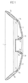
- the valve plate of a valve member is a Additional control valve device shown in cross section. He consists of a plate-shaped base body 1, in one first step made of a metallic material becomes.
- the plate-shaped base body 1 has a outside through annular area 1a. Between the annular portion 1a and a tubular inner portion 1b, which is funnel-shaped, are each two Recesses for each disc-shaped part. 2 shown.
- the second step becomes one disc-shaped part 2 made of a rubber with his Outside area 2a on each of a peripheral edge region 1a ' placed on the convex outside of the base body 1.
- a third step is the connecting of the respective disc-shaped part 2 with the peripheral edge region 1a ' by vulcanization.
- each revolving Edge region 1a ' is made smaller than the wall thickness of annular region 1a. This is also realized by that the respective peripheral edge region 1a 'opposite convex outside of the annular portion 1a in the direction is arranged offset on the inner wall of the valve disk. As a result, a convex outside of the Valve plates without larger heels achieved what is special beneficial to the flow conditions in the Additional control valve device affects.
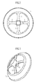
- Fig. 2 is a plan view of a plate-shaped Basic body shown.
- the plate-shaped body has four recesses 4, which are designed uniformly and each separated by webs 3.
- the plate-shaped base body is three-dimensional shown in FIG. 2.
- the tubular inner part 1b is used the fixation of the shaft (not shown).
- valve member is shown in cross section. Of the Shank 5 is at the junction 6 with the tubular Inner part 1b of the valve disc connected.
Landscapes
- Engineering & Computer Science (AREA)
- Chemical & Material Sciences (AREA)
- Combustion & Propulsion (AREA)
- Mechanical Engineering (AREA)
- General Engineering & Computer Science (AREA)
- Manufacturing & Machinery (AREA)
- Check Valves (AREA)
- Multiple-Way Valves (AREA)
- Lift Valve (AREA)
Abstract
Description
DE 101 37 828 A1 wird eine in einem Einlasskanal einer Kolbenbrennkraftmaschine angeordnete Zusatzsteuerventileinrichtung in ihrer Funktionsweise beschrieben. Bei einer solchen Zusatzsteuerventileinrichtung ist es vorgesehen, ein Ventilglied anzuordnen, das im Wesentlichen pilzförmig ausgebildet ist. Bei diesem Ventilglied ist an einem Schaft ein hutförmiger Ventilteller angeordnet, der zu der vom Einlassventil abgewandten Seite hin konkav mit einem Scheitelpunkt ausgebildet ist. Innerhalb einer Führung des Schaftes sind Federn angeordnet, durch die eine Art schwingungsfähiges System geschaffen wird. Die Eigenfrequenz des schwingungsfähigen Systems wird dabei durch die Federkonstanten und das Gewicht des Ventilgliedes gegeben. Die magnetischen Eigenschaften des Ventilgliedes werden unter anderem durch den Wandstärkenverlauf im magnetischen Wirkbereich gewährleistet. Bei diesem Ventilglied ist jedoch nachteilig, dass bei der Großserienfertigung durch Kaltfließpressen gerade im Bereich erforderlicher dünner Wanddicken relativ hohe Werkzeugkräfte benötigt werden, was zu einem relativ schnellen Werkzeugverschleiß führt.
- Fig. 1
- zeigt den Ventilteller im Querschnitt.
- Fig. 2
- zeigt den tellerförmigen Grundkörper in der Draufsicht.
- Fig. 3
- zeigt den tellerförmigen Grundkörper in dreidimensionaler Form.
- Fig. 4
- zeigt das Ventilglied mit dem Schaft im Querschnitt.
Claims (5)
- Verfahren zur Herstellung eines Ventiltellers eines Ventilgliedes einer Zusatzsteuerventileinrichtung, bei dem in einem ersten Schritt ein tellerförmiger Grundkörper (1) aus einem metallischen Werkstoff hergestellt wird, der außen einen durchgehend ringförmigen Bereich (1a) aufweist und der zwischen dem ringförmigen Bereich (1a) und einem rohrförmigen Innenteil (1b) mindestens zwei Aussparungen (4) aufweist, bei dem in einem zweiten Schritt jeweils ein scheibenförmiges Teil (2) aus einem Kautschuk mit seinem Außenbereich (2a) auf jeweils einen umlaufenden Randbereich (1a'), der eine Aussparung (4) umgibt, auf die konvexe Außenseite des Grundkörpers (1) aufgelegt wird und in einem dritten Schritt das scheibenförmige Teil (2) mit dem umlaufenden Randbereich (1a') durch Aufvulkanisieren verbunden wird.
- Verfahren nach Anspruch 1, bei dem vier Aussparungen (4), die gleichförmig gestaltet sind, angeordnet werden, die jeweils voneinander durch Stege (3) getrennt sind.
- Verfahren nach Anspruch 1 oder Anspruch 2, bei dem scheibenförmige Teile (2) aus Fluor-Kautschuk oder hydriertem Nytril-Butadien-Kautschuk eingesetzt werden.
- Verfahren nach einem der Ansprüche 1 bis 3, bei dem die Wanddicke des jeweiligen umlaufenden Randbereiches (1a') kleiner ausgeführt wird als die Wanddicke des ringförmigen Bereiches (1a).
- Verfahren nach Anspruch 4, bei der der jeweilige umlaufende Randbereich (1a') gegenüber der konvexen Außenseite des ringförmigen Bereiches (1a) in Richtung auf die Innenwand des Ventiltellers versetzt angeordnet wird.
Applications Claiming Priority (2)
| Application Number | Priority Date | Filing Date | Title |
|---|---|---|---|
| DE10335128A DE10335128A1 (de) | 2003-07-31 | 2003-07-31 | Verfahren zur Herstellung eines Ventiltellers eines Ventilgliedes einer Zusatzsteuerventileinrichtung |
| DE10335128 | 2003-07-31 |
Publications (2)
| Publication Number | Publication Date |
|---|---|
| EP1503057A1 true EP1503057A1 (de) | 2005-02-02 |
| EP1503057B1 EP1503057B1 (de) | 2009-01-28 |
Family
ID=33521510
Family Applications (1)
| Application Number | Title | Priority Date | Filing Date |
|---|---|---|---|
| EP04102770A Expired - Lifetime EP1503057B1 (de) | 2003-07-31 | 2004-06-17 | Verfahren zur Herstellung eines Ventiltellers eines Ventilgliedes einer Zusatzsteuerventileinrichtung |
Country Status (2)
| Country | Link |
|---|---|
| EP (1) | EP1503057B1 (de) |
| DE (2) | DE10335128A1 (de) |
Citations (6)
| Publication number | Priority date | Publication date | Assignee | Title |
|---|---|---|---|---|
| GB1100609A (en) * | 1964-12-23 | 1968-01-24 | Ver Armaturen Gmbh | Slide valve |
| GB1260541A (en) * | 1968-03-23 | 1972-01-19 | Luigi Giovanni Valdenazzi | An anti-blast valve |
| US4271862A (en) * | 1978-05-08 | 1981-06-09 | Inter Ocean N.V. | Check valve and method of manufacturing said check valve |
| US4488566A (en) * | 1983-06-22 | 1984-12-18 | The Singer Company | Thermally responsive slam shut valve assembly |
| US5584270A (en) * | 1993-05-05 | 1996-12-17 | Firma Carl Freudenberg | Intake pipe for an internal combustion engine |
| DE10137828A1 (de) * | 2001-08-02 | 2003-02-20 | Meta Motoren Energietech | In einem Einlasskanal einer Kolbenbrennkraftmaschine angeordnete Zusatzsteuerventileinrichtung |
Family Cites Families (3)
| Publication number | Priority date | Publication date | Assignee | Title |
|---|---|---|---|---|
| JP2000193006A (ja) * | 1998-12-22 | 2000-07-14 | Fukoku Co Ltd | 板バネ一体型コアおよびその製造方法 |
| JP2000193007A (ja) * | 1998-12-22 | 2000-07-14 | Fukoku Co Ltd | 板バネ一体型コアおよびその製造方法 |
| DE10029299C2 (de) * | 2000-06-14 | 2003-03-27 | Daimler Chrysler Ag | Mehrteilig zusammengesetztes Ventil für Hubkolbenmaschinen |
-
2003
- 2003-07-31 DE DE10335128A patent/DE10335128A1/de not_active Withdrawn
-
2004
- 2004-06-17 EP EP04102770A patent/EP1503057B1/de not_active Expired - Lifetime
- 2004-06-17 DE DE502004008936T patent/DE502004008936D1/de not_active Expired - Lifetime
Patent Citations (6)
| Publication number | Priority date | Publication date | Assignee | Title |
|---|---|---|---|---|
| GB1100609A (en) * | 1964-12-23 | 1968-01-24 | Ver Armaturen Gmbh | Slide valve |
| GB1260541A (en) * | 1968-03-23 | 1972-01-19 | Luigi Giovanni Valdenazzi | An anti-blast valve |
| US4271862A (en) * | 1978-05-08 | 1981-06-09 | Inter Ocean N.V. | Check valve and method of manufacturing said check valve |
| US4488566A (en) * | 1983-06-22 | 1984-12-18 | The Singer Company | Thermally responsive slam shut valve assembly |
| US5584270A (en) * | 1993-05-05 | 1996-12-17 | Firma Carl Freudenberg | Intake pipe for an internal combustion engine |
| DE10137828A1 (de) * | 2001-08-02 | 2003-02-20 | Meta Motoren Energietech | In einem Einlasskanal einer Kolbenbrennkraftmaschine angeordnete Zusatzsteuerventileinrichtung |
Also Published As
| Publication number | Publication date |
|---|---|
| DE502004008936D1 (de) | 2009-03-19 |
| DE10335128A1 (de) | 2005-02-24 |
| EP1503057B1 (de) | 2009-01-28 |
Similar Documents
| Publication | Publication Date | Title |
|---|---|---|
| DE69928380T2 (de) | Dämpfer für freilaufkupplung | |
| DE3609251C2 (de) | ||
| DE19804765C2 (de) | Platzhalter mit einstellbarer axialer Länge | |
| DE60223924T2 (de) | Kurbelwellendämpfer mit integrierter indexscheibe und herstellverfahren dafür | |
| DE69326985T2 (de) | Brennstoffeinspritzventil mit hochdruckbegrenzungsventil | |
| DE102011013113A1 (de) | Kolben für einen Verbrennungsmotor und Verfahren zu seiner Herstellung | |
| DE102009014907A1 (de) | Fluiddruckstoßdämpfer | |
| DE102015101950A1 (de) | Stanzniet und Verfahren zum Herstellen einer Stanznietverbindung | |
| EP1546547A1 (de) | Kraftstoffeinspritzventil für brennkraftmaschinen | |
| DE10239207A1 (de) | Elektromagnetisches Hydraulikventil, insbesondere Proportionalventil zur Steuerung einer Vorrichtung zur Drehwinkelverstellung einer Nockenwelle gegenüber einer Kurbelwelle einer Brennkraftmaschine | |
| EP1636474A2 (de) | Verfahren zur herstellung eines einteiligen kolbens für einen verbrennungsmotor | |
| EP0745178B1 (de) | Mehrfachnocken | |
| EP1805406A1 (de) | Verfahren zur herstellung eines kolbens einer brennkraftmaschine zur bildung einer bewehrung einer brennraummulde des kolbens | |
| DE102014207631A1 (de) | Nockenwellenversteller mit zusätzlichem Formschluss zwischen drehmomentübertragenden Teilen | |
| DE102007022266A1 (de) | Anordnung eines variablen Ventiltriebs | |
| EP1503057B1 (de) | Verfahren zur Herstellung eines Ventiltellers eines Ventilgliedes einer Zusatzsteuerventileinrichtung | |
| DE202004018828U1 (de) | Geschmiedeter Spannsatz | |
| EP1224049A1 (de) | Gedämpftes werkzeug | |
| EP1063391B1 (de) | Ventiltrieb für eine Verbrennungskraftmaschine | |
| DE3728142A1 (de) | Zusammengesetzte kurbelwelle und verfahren zu ihrer herstellung | |
| EP1518044B1 (de) | Ventilglied für eine zusatzsteuerventileinrichtung | |
| EP0762023B1 (de) | Sitzventil | |
| DE102006049996A1 (de) | Planetenrad-Einheit und Verfahren zur Herstellung einer Planetenrad-Einheit | |
| EP3002447B1 (de) | Kraftstoffeinspritzvorrichtung | |
| DE102009011813A1 (de) | Kalibrierwerkzeug für die Fertigung von Tellerfedern |
Legal Events
| Date | Code | Title | Description |
|---|---|---|---|
| PUAI | Public reference made under article 153(3) epc to a published international application that has entered the european phase |
Free format text: ORIGINAL CODE: 0009012 |
|
| AK | Designated contracting states |
Kind code of ref document: A1 Designated state(s): AT BE BG CH CY CZ DE DK EE ES FI FR GB GR HU IE IT LI LU MC NL PL PT RO SE SI SK TR |
|
| AX | Request for extension of the european patent |
Extension state: AL HR LT LV MK |
|
| 17P | Request for examination filed |
Effective date: 20050307 |
|
| AKX | Designation fees paid |
Designated state(s): CZ DE FR IT |
|
| RAP1 | Party data changed (applicant data changed or rights of an application transferred) |
Owner name: CONTINENTAL AUTOMOTIVE GMBH |
|
| GRAP | Despatch of communication of intention to grant a patent |
Free format text: ORIGINAL CODE: EPIDOSNIGR1 |
|
| GRAS | Grant fee paid |
Free format text: ORIGINAL CODE: EPIDOSNIGR3 |
|
| GRAA | (expected) grant |
Free format text: ORIGINAL CODE: 0009210 |
|
| AK | Designated contracting states |
Kind code of ref document: B1 Designated state(s): CZ DE FR IT |
|
| REF | Corresponds to: |
Ref document number: 502004008936 Country of ref document: DE Date of ref document: 20090319 Kind code of ref document: P |
|
| PLBE | No opposition filed within time limit |
Free format text: ORIGINAL CODE: 0009261 |
|
| STAA | Information on the status of an ep patent application or granted ep patent |
Free format text: STATUS: NO OPPOSITION FILED WITHIN TIME LIMIT |
|
| 26N | No opposition filed |
Effective date: 20091029 |
|
| PGFP | Annual fee paid to national office [announced via postgrant information from national office to epo] |
Ref country code: DE Payment date: 20120630 Year of fee payment: 9 |
|
| PGFP | Annual fee paid to national office [announced via postgrant information from national office to epo] |
Ref country code: FR Payment date: 20120705 Year of fee payment: 9 |
|
| PGFP | Annual fee paid to national office [announced via postgrant information from national office to epo] |
Ref country code: IT Payment date: 20120626 Year of fee payment: 9 |
|
| PGFP | Annual fee paid to national office [announced via postgrant information from national office to epo] |
Ref country code: CZ Payment date: 20130611 Year of fee payment: 10 |
|
| REG | Reference to a national code |
Ref country code: FR Ref legal event code: ST Effective date: 20140228 |
|
| REG | Reference to a national code |
Ref country code: DE Ref legal event code: R119 Ref document number: 502004008936 Country of ref document: DE Effective date: 20140101 |
|
| PG25 | Lapsed in a contracting state [announced via postgrant information from national office to epo] |
Ref country code: DE Free format text: LAPSE BECAUSE OF NON-PAYMENT OF DUE FEES Effective date: 20140101 |
|
| PG25 | Lapsed in a contracting state [announced via postgrant information from national office to epo] |
Ref country code: IT Free format text: LAPSE BECAUSE OF NON-PAYMENT OF DUE FEES Effective date: 20130617 Ref country code: FR Free format text: LAPSE BECAUSE OF NON-PAYMENT OF DUE FEES Effective date: 20130701 |
|
| PG25 | Lapsed in a contracting state [announced via postgrant information from national office to epo] |
Ref country code: CZ Free format text: LAPSE BECAUSE OF NON-PAYMENT OF DUE FEES Effective date: 20140617 |