EP1502786A1 - Düsenanordnung in einem Fahrzeug - Google Patents
Düsenanordnung in einem Fahrzeug Download PDFInfo
- Publication number
- EP1502786A1 EP1502786A1 EP04016430A EP04016430A EP1502786A1 EP 1502786 A1 EP1502786 A1 EP 1502786A1 EP 04016430 A EP04016430 A EP 04016430A EP 04016430 A EP04016430 A EP 04016430A EP 1502786 A1 EP1502786 A1 EP 1502786A1
- Authority
- EP
- European Patent Office
- Prior art keywords
- nozzle
- carrier
- arrangement according
- nozzle arrangement
- crash
- Prior art date
- Legal status (The legal status is an assumption and is not a legal conclusion. Google has not performed a legal analysis and makes no representation as to the accuracy of the status listed.)
- Granted
Links
Images




Classifications
-
- B—PERFORMING OPERATIONS; TRANSPORTING
- B60—VEHICLES IN GENERAL
- B60H—ARRANGEMENTS OF HEATING, COOLING, VENTILATING OR OTHER AIR-TREATING DEVICES SPECIALLY ADAPTED FOR PASSENGER OR GOODS SPACES OF VEHICLES
- B60H1/00—Heating, cooling or ventilating devices
- B60H1/00507—Details, e.g. mounting arrangements, desaeration devices
- B60H1/00514—Details of air conditioning housings
- B60H1/0055—Details of air conditioning housings the housing or parts thereof being integrated in other devices, e.g. dashboard
-
- B—PERFORMING OPERATIONS; TRANSPORTING
- B60—VEHICLES IN GENERAL
- B60H—ARRANGEMENTS OF HEATING, COOLING, VENTILATING OR OTHER AIR-TREATING DEVICES SPECIALLY ADAPTED FOR PASSENGER OR GOODS SPACES OF VEHICLES
- B60H1/00—Heating, cooling or ventilating devices
- B60H1/34—Nozzles; Air-diffusers
-
- B—PERFORMING OPERATIONS; TRANSPORTING
- B60—VEHICLES IN GENERAL
- B60R—VEHICLES, VEHICLE FITTINGS, OR VEHICLE PARTS, NOT OTHERWISE PROVIDED FOR
- B60R21/00—Arrangements or fittings on vehicles for protecting or preventing injuries to occupants or pedestrians in case of accidents or other traffic risks
- B60R21/02—Occupant safety arrangements or fittings, e.g. crash pads
- B60R21/09—Control elements or operating handles movable from an operative to an out-of-the way position, e.g. pedals, switch knobs, window cranks
Definitions
- the invention relates to a nozzle arrangement in a vehicle, in particular in a motor vehicle, according to the preamble of claim 1.
- the side and center nozzle in motor vehicles are usually at one Support or other rigid component, such as an instrument panel, firmly attached and are often in the impact area of the head by driver or passenger in a crash case.
- the nozzle is common plugged into the formed in the carrier air duct, for what the air duct extended in the insertion area.
- Particularly critical here is the Central nozzle, whereby due to the greatly reduced space between Air conditioning and dashboard a block-like configuration of the nozzle assembly for constructive reasons.
- the nozzle is externally put on the air channel formed by the carrier, wherein the nozzle strikes directly on the carrier.
- a nozzle arrangement in which the nozzle or at least the front part thereof if necessary, i. in case of a Crashes and an impact of an object or a head, accordingly the deformation of the dashboard, in or on the nozzle is arranged, can be moved in the direction of the carrier.
- the carrier is to be understood in accordance with the present invention, so that other, a nozzle-bearing parts are understood by it should.
- the nozzle assembly is on Due to the displacement a certain deformation path for the nozzle opposite given the carrier, so that the nozzle in the crash case not as rigid Projection protrudes while the adjacent area of the dashboard deformed.
- the deformation paths of the surface of the dashboard in the case of a head crash in a crash are usually between 30 and 100 mm, which is why the outer area of the nozzle has a corresponding Way in the event of a crash should be retractable, allowing injuries due to the nozzle can be safely avoided and the Impact of the head as large as possible.
- the nozzle is at least partially retractable into the carrier, wherein
- the nozzle is inserted into an opening of the carrier. It may be preferred by means of an elastomer a sliding seat the connection between the carrier and nozzle form, which ensures the displacement in case of need.
- the nozzle may also be attached to the carrier, in which case Preferably predetermined breaking points are provided on the nozzle, which is a shift allow the nozzle at least partially on the carrier.
- Prefers are one or more predetermined breaking points transverse to the longitudinal direction of the nozzle between a flap part and an air guiding part in which, for example Slats are arranged, provided so that the nozzle in the event of a crash Splits.
- a cross-sectional widening or a cross-sectional reduction is preferred provided between the flap part and the air guide part.
- a division be provided in the longitudinal direction of the nozzle, so that the Splits nozzle in the event of a crash and slides over the carrier.
- An elastic connection may be provided between the carrier and the nozzle be, which allows the relative movement to the carrier in the event of a crash.
- a predetermined breaking point be provided, which fulfills the same function. Also a combination of elastic connection and predetermined breaking point is possible in principle.
- the nozzle is designed in several parts, wherein the connection between the individual parts of the nozzle in the event of a crash is solved. It can preferably clips connections or frictional connections, however Any other compounds may be provided, which are in a solve given force.
- the nozzle assembly forms an air duct with substantially constant cross section or seen in the direction of air flow at most with small cross-sectional changes. This is the transition between the nozzle and the carrier preferably designed such that fluidically no edges are present.
- part of the nozzle is an area or part of a foil, a wave-like or bellows-shaped collapsible Material is formed. This allows an almost complete Alignment of the surfaces of the dashboard and the nozzle (especially the grill) in case of deformation.
- FIG. 1 An inventive arrangement belonging to a ventilation system 1 is in a motor vehicle in a dashboard 2, which in Fig. 1 indicated only schematically attached.
- a side nozzle shown.
- the center nozzle and the other side nozzle are corresponding educated.
- the nozzle assembly 1 has one of a corresponding formed on formed sheet carrier 3 and a nozzle 4, which is inserted in the carrier 3.
- the carrier 3 in Fig. 1 is only in the range its air outlet opening shown.
- the nozzle 4 is integrally formed, wherein in the interior of the nozzle a schematic indicated flap and slats not shown arranged are, which form a spoiler 5 and to control the Serve vehicle interior supplied air.
- the embodiment of the same can be any, but their movement mechanics or elektrik formed such that it faces a displacement of the nozzle 4 the carrier 3 is not hindered.
- a preferably elastomeric ring 16 forms a sliding seat and provides a sliding connection between Carrier 3 and nozzle 4.
- the cross section of this ring it can in Deviation from the rectangular profile shown in Fig. 1 also circular be or have other possible geometric shapes.
- the carrier 3 has the passage of an air conditioner, which with the Connected ventilation system and of which in Fig. 1, an air duct 6 is shown is an opening 7, coming air.
- This opening 7 is such trained that they a facing the dashboard 2, circulating Edge 8 having a decreasing cross-section, wherein with respect to the transition to Fig. 1 is referenced.
- the nozzle 4 is partially inserted, the Nozzle 4 in the region close to the carrier a shape adapted to the transition which is hereinafter referred to as spoiler 9, so that the Air flow is affected as low as possible.
- the spoiler 9 is according to the Embodiment present elastic, so that it is good adjusts to the edge 8 and compensates for dimensional inaccuracies.
- the spoiler 9 be made of a hard material, in particular of the same Material like the other part of the wall of the nozzle 4. Also, the Sealing profile of the spoiler 9 made separately and attached to the nozzle 4 become.
- an elastically formed spoiler 9 can also a foamed spoiler can be used, for example, by means of two-component injection molding in one step with the wall of the nozzle 4 can be produced.
- the spoiler also on the carrier be formed so that simplifies the shape of the nozzle.
- the spoiler can be attached as an additional part to the carrier, this has a predetermined breaking point, if it is made of a hard material is.
- it may be made of a soft elastomer, in particular Two-component technology to be made.
- the dashboard 2 In the event of a crash and the impact of an object or a Head deforms the dashboard 2 and the nozzle 4 is in the longitudinal direction pushed into the carrier 3.
- the resistance to be overcome here is relatively low.
- to the positioning of the nozzle 4 in Carrier 3 provided projections predetermined breaking points (not shown), which release the nozzle 4 in the direction of the carrier 3 in the event of a crash.
- the maximum possible displacement of the nozzle 4 is equal to or greater as the maximum expected deformation of the instrument panel 2. This Injuries can be caused by a deformation of the dashboard 2 avoid protruding areas of the nozzle 4.
- the carrier 103 in Fig. 2 only in Area of its air outlet opening shown.
- the nozzle 104 is integrally formed, wherein inside the nozzle a schematically indicated flap 105 'and fins 105 "are arranged, which form an air guiding device 105 and for controlling the vehicle interior serve supplied air.
- the embodiment of the same can, according to the first embodiment, be any, however their movement mechanics or electrics is designed such that they a displacement of the nozzle 104 relative to the carrier 103 is not hindered, however, in the area indicated by ellipses in FIG. 2, at least a predetermined breaking point (not shown) is provided on the will be discussed later.
- the carrier 103 has an opening 107, which is designed in such a way that that it has a peripheral edge 108 facing the dashboard, which has a decreasing cross-section.
- the edge 108 has at its end a cross-section, that of the flow channel the nozzle 104 corresponds, as can be seen from Fig. 2.
- Nozzle 104 is provided an edge with a larger cross section, the over the edge 108 of the carrier 103 is attached. Additional sealants can be arranged in this area.
- the predetermined breaking point can extend in the longitudinal direction of the nozzle 104, so that the wall of the nozzle 104 in the event of a crash and an impact of a Object or a head on the dashboard in the area the nozzle 104 is slit longitudinally and onto the carrier 103 too moved.
- the Edge 108 of the carrier and the voltage applied to the carrier 103 portion of the nozzle 104 correspondingly rounded or bevelled.
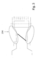
- Fig. 3 shows a third embodiment, which is essentially the second embodiment, but in which by the ellipses marked area instead of a predetermined breaking point at least one elastic region provided, the corresponding evasive movement at least the portion of the nozzle located on the dashboard 204 allows.
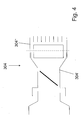
- a fourth embodiment is shown, which is a two-part Design of the nozzle 304 shows. Otherwise, the fourth embodiment corresponds the illustrated in Fig. 2, the second embodiment.
- the contact area of the two parts 304 'and 304 "of the nozzle is used 304 as a predetermined breaking point, so that in turn a longitudinal displacement of the front, in or on the dashboard arranged portion of the nozzle 304 in If necessary, is guaranteed.
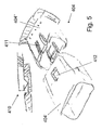
- Fig. 5 shows a fifth embodiment, wherein the nozzle 404 in two parts is constructed, namely with a flap part 404 'and a grill part 404 ", which forms the part arranged in the dashboard.
- the grill part 404 " is put on the flap part 404 ', wherein the positioning takes place by means of two clip connections 410, one at the top and one at the bottom of the nozzle 404.
- Two Spring arms 411 are in this case the grill part 404 "formed in recesses or openings 412 resiliently engage, which in the flap part 404 ' are provided.
- the flap portion 404 ' may be attached to the grill portion 404 " can the arrangement of fasteners on the flap part and the grill part be reversed.
- the number and arrangement of fasteners vary.
- the spring force of the two spring arms 411 can be easily overcome so that the grill part 404 "without much effort slides over the flap part 404 '.
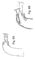
- FIGS. 6A and 6B show a sixth exemplary embodiment. which substantially corresponds to the first embodiment, however takes place, as can be seen in particular from Fig. 6B, no pure longitudinal displacement if necessary, but there is a curve movement, mainly in the back area.
- a seventh embodiment is shown, which is substantially corresponds to the first embodiment, but the spoiler 609 is on Carrier 603 attached and with a circumferential predetermined breaking point 613 on provided facing the nozzle 604 side.
- a sealing element 614 is provided in the space between Nozzle 604 and carrier 603.
- the nozzle 704 is formed in two parts, wherein the dividing line of the two Parts 704 'and 704 "extends in the longitudinal direction of the nozzle 704 and the two Parts 704 'and 704 ", for example by means not shown clips connections or other types of connections. These clips connections are, for example, with predetermined breaking points, not shown provided, which, if necessary, a breakup of the Allow nozzle 704 so that they continue to slide over the carrier 703 can.
- Figures 9A and 9B show a ninth embodiment, wherein about the carrier 803, for example, a part 804 'formed by a foil 815. the nozzle 804 is pushed. In this case, this part is 804 'with a wave structure bellows formed and pushed onto the carrier 803. With his the other side is the part 804 'with the second part 804 "of the nozzle 804 fixed connected, wherein the two parts 804 'and 804 "also integrally formed could be.
- the second part 804 "of the nozzle 804 is at its the carrier 803 remote area firmly connected to the dashboard and can move together with the same relative to the carrier 803 (see. Fig. 9B), so that in case of need, a relative movement between the carrier 803 and nozzle 804 is possible. It moves the arranged in the dashboard Part 804 "of the nozzle 804 according to the same, so that the risk of injury is minimized.
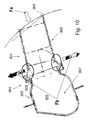
- a tenth embodiment is shown, in which a carrier 903 to the passage of an air conditioner, with the ventilation system connected and of which in Fig. 10, an air duct 906 is shown, incoming air, having an opening 907.
- This opening 907 is with a formed to the dashboard edge 908.
- the nozzle 904 is not inserted into the carrier 903 but enclosing or inverting the edge 908 of the opening 907, attached, wherein the nozzle 904 in the region near the carrier a the Transition adapted shape.
- the opening 907 In the area of the connector, has the opening 907 in about the same inner diameter as the nozzle 904, wherein the tubular end of the nozzle 904 in the region of the opening 907 of the carrier 903 conically flared outwards and with a cylindrical End portion is provided, which over the edge 908 of the opening 907 can be plugged.
- a spoiler (not shown in Figure 10) in the transition region from the carrier 903 to the nozzle 904 for the least possible influence ensure the air flow.
- the spoiler can be made elastic so that it adapts well to the edge 908 and dimensional inaccuracies balances.
- the preparation is preferably carried out by means of two-component injection molding.
- the spoiler can be made of a hard material be, in particular of the same material as the other part of the wall the nozzle 904.
- the sealing profile of the spoiler can be separated manufactured and attached to the nozzle 904.
- a elastically formed spoiler can also be a foamed spoiler used be, for example, by means of two-component injection molding can be made in one step with the wall of the nozzle.
- sealing lips may be provided which have a corresponding profile have, which prevents rolling up.
Landscapes
- Physics & Mathematics (AREA)
- Thermal Sciences (AREA)
- Engineering & Computer Science (AREA)
- Mechanical Engineering (AREA)
- Air-Conditioning For Vehicles (AREA)
- Instrument Panels (AREA)
- Servomotors (AREA)
- Nozzles (AREA)
- Body Structure For Vehicles (AREA)
- Refuge Islands, Traffic Blockers, Or Guard Fence (AREA)
- Vibration Dampers (AREA)
Abstract
Description
- Fig. 1
- einen vereinfacht dargestellten Schnitt durch eine Düsenanordnung gemäß einem ersten Ausführungsbeispiel,
- Fig. 2
- einen vereinfacht dargestellten Schnitt durch eine Düsenanordnung gemäß einem zweiten Ausführungsbeispiel,
- Fig. 3
- einen vereinfacht dargestellten Schnitt durch eine Düsenanordnung gemäß einem dritten Ausführungsbeispiel,
- Fig. 4
- einen vereinfacht dargestellten Schnitt durch eine Düsenanordnung gemäß einem vierten Ausführungsbeispiel,
- Fig. 5
- eine perspektivische Explosionsdarstellung eines fünften Ausführungsbeispiels, wobei links oben ein Schnitt in Längsrichtung einer Clips-Verbindung dargestellt ist,
- Fig. 6A und 6B
- vereinfacht dargestellte Schnitte durch ein sechstes Ausführungsbeispiel, wobei Fig. 6A die normale Position der Düse und Fig. 6B die Position der Düse nach einem Crash darstellt,
- Fig. 7
- einen ausschnittsweise dargestellten Schnitt durch ein siebtes Ausführungsbeispiel,
- Fig. 8A und 8B
- vereinfacht dargestellte Schnitte durch ein achtes Ausführungsbeispiel, wobei Fig. 8A die normale Position der Düse und Fig. 8B die Position der Düse nach einem Crash darstellt,
- Fig. 9A und 9B
- vereinfacht dargestellte Schnitte durch ein neuntes Ausführungsbeispiel, wobei Fig. 9A die normale Position on der Düse und Fig. 9B die Position der Düse nach einem Crash darstellt, und
- Fig. 10
- einen vereinfacht dargestellten Schnitt durch eine Düsenanordnung gemäß einem zehnten Ausführungsbeispiel.
Claims (18)
- Düsenanordnung in einem Fahrzeug, insbesondere einem Kraftfahrzeug, mit mindestens einer Düse (4, 104, 204, 304, 404, 604, 704, 804, 904), die an einem Träger (3, 103, 603, 703, 803, 903) angeordnet ist, dadurch gekennzeichnet, dass die Düse (4, 104, 204, 304, 404, 604, 704, 804, 904) im Crash-Fall gegenüber dem Träger (3, 103, 603, 703, 803, 903) verschiebbar ist.
- Düsenanordnung nach Anspruch 1, dadurch gekennzeichnet, dass die Düse (4, 104, 204, 304, 404, 604, 704, 804, 904) in den Träger (3, 103, 603, 703, 803, 903) eingesteckt oder auf denselben aufgesteckt ist.
- Düsenanordnung nach Anspruch 1 oder 2, dadurch gekennzeichnet, dass die Düse (4, 604) in dem Träger (3, 603) zumindest teilweise versenkbar ist.
- Düsenanordnung nach einem der vorhergehenden Ansprüche, dadurch gekennzeichnet, dass eine elastische Verbindung zwischen dem Träger und der Düse (204) vorgesehen ist, die im Crash-Fall die Relativbewegung zum Träger ermöglicht.
- Düsenanordnung nach einem der vorhergehenden Ansprüche, dadurch gekennzeichnet, dass mindestens eine Sollbruchstelle (613) vorgesehen ist, die im Crash-Fall die Relativbewegung zum Träger (3, 103, 603, 703) freigibt.
- Düsenanordnung nach einem der vorhergehenden Ansprüche, dadurch gekennzeichnet, dass die Düse (304, 404, 704) mehrteilig ausgebildet ist, wobei die Verbindung zwischen den einzelnen Teilen (304', 304", 404', 404", 704', 704") der Düse (304, 404, 704) im Crash-Fall gelöst wird.
- Düsenanordnung nach einem der vorstehenden Ansprüche, dadurch gekennzeichnet, dass die Düse (304, 404, 704, 804) mehrteilig ausgebildet ist, wobei mindestens ein Teil (304', 304", 404', 404", 704', 704", 804', 804") vorgesehen ist, das über eine Luftauslass-Öffnung (7, 107) im Träger (3, 103, 603, 703, 803) gesteckt ist.
- Düsenanordnung nach Anspruch 7, dadurch gekennzeichnet, dass im Teil (304', 404', 704', 704") eine Klappe angeordnet ist.
- Düsenanordnung nach einem der Ansprüche 6 bis 8, dadurch gekennzeichnet, dass auf den Teil (304', 404') ein zweites Düsen-Teil (304", 404") gesteckt ist.
- Düsenanordnung nach Anspruch 9, dadurch gekennzeichnet, dass im zweiten Düsen-Teil (304", 404") zumindest ein Teil einer Luftleitvorrichtung (5, 105) angeordnet ist.
- Düsenanordnung nach einem der Ansprüche 6 bis 10, dadurch gekennzeichnet, dass die einzelnen Teile (304', 304", 404', 404") der mehrteilig ausgebildeten Düse (304, 404) jeweils auf einen mit einem kleineren Querschnitt ausgebildeten Bereich des Trägers (703) und/oder des benachbarten, trägernäheren Teiles (304', 404') aufgesteckt sind, wobei der aufgesteckte Teil (304', 304", 404', 404") bereichsweise einen etwas größeren Querschnitt aufweist.
- Düsenanordnung nach einem der vorhergehenden Ansprüche, dadurch gekennzeichnet, dass die Düsenanordnung (1, 101) einen Luftkanal (6) mit im Wesentlichen gleich bleibenden Querschnitt oder in Strömungsrichtung der Luft gesehen höchstens mit geringen Querschnittsänderungen bildet.
- Düsenanordnung nach einem der vorhergehenden Ansprüche, dadurch gekennzeichnet, dass wenigstens ein Teil der Düse (804) ein Bereich oder Teil (804') ist, der von einer Folie (815), einem wellenartig- oder faltenbalgartigen zusammenschiebbaren Material gebildet ist.
- Düsenanordnung nach einem der vorhergehenden Ansprüche, dadurch gekennzeichnet, dass die Düsenanordnung (1, 101) im Crash-Fall einen Deformationsweg von mindestens 30 mm, insbesondere 100 mm, aufweist.
- Düsenanordnung nach einem der vorhergehenden Ansprüche, dadurch gekennzeichnet, dass starre Bauteile nur außerhalb des Deformationswegs der Düsenanordnung (1, 101) angeordnet sind.
- Düsenanordnung nach einem der vorhergehenden Ansprüche, dadurch gekennzeichnet, dass zwischen dem Träger und der Düse und/oder zwei Teilen (404', 404", 704', 704") der Düse (404. 704) mindestens eine Clips-Verbindung (410) vorgesehen ist.
- Düsenanordnung nach einem der vorhergehenden Ansprüche, dadurch gekennzeichnet, dass zwischen dem Träger und der Düse und/oder zwei Teilen (404', 404", 704', 704") der Düse (404. 704) mindestens eine Sollbruchstelle und/oder eine Verschiebestelle vorgesehen ist.
- Düsenanordnung nach einem der vorhergehenden Ansprüche, dadurch gekennzeichnet, dass die Düse (704) in Längsrichtung geteilt zweiteilig ausgebildet ist.
Applications Claiming Priority (2)
| Application Number | Priority Date | Filing Date | Title |
|---|---|---|---|
| DE10334569 | 2003-07-28 | ||
| DE10334569 | 2003-07-28 |
Publications (2)
| Publication Number | Publication Date |
|---|---|
| EP1502786A1 true EP1502786A1 (de) | 2005-02-02 |
| EP1502786B1 EP1502786B1 (de) | 2006-10-11 |
Family
ID=33521455
Family Applications (1)
| Application Number | Title | Priority Date | Filing Date |
|---|---|---|---|
| EP04016430A Expired - Lifetime EP1502786B1 (de) | 2003-07-28 | 2004-07-13 | Düsenanordnung in einem Fahrzeug |
Country Status (6)
| Country | Link |
|---|---|
| US (1) | US7029389B2 (de) |
| EP (1) | EP1502786B1 (de) |
| JP (1) | JP4504131B2 (de) |
| AT (1) | ATE342180T1 (de) |
| DE (2) | DE502004001706D1 (de) |
| ES (1) | ES2274350T3 (de) |
Cited By (3)
| Publication number | Priority date | Publication date | Assignee | Title |
|---|---|---|---|---|
| WO2006000715A1 (fr) * | 2004-06-14 | 2006-01-05 | Faurecia Interieur Industrie | Aerateur pour vehicule automobile, ensemble forme par cet aerateur et une facade d'equipement interieur de vehicule, et procede d'assemblage de cet ensemble |
| EP1810855A1 (de) * | 2006-01-18 | 2007-07-25 | Behr GmbH & Co. KG | Luftausströmer, insbesondere für ein Belüftungssystem eines Fahrzeugs |
| US20140342651A1 (en) * | 2013-05-15 | 2014-11-20 | Eberspächer Climate Control Systems GmbH & Co. KG | Air discharge assembly unit, especially for routing air into the interior space of a vehicle |
Families Citing this family (9)
| Publication number | Priority date | Publication date | Assignee | Title |
|---|---|---|---|---|
| US7247088B2 (en) * | 2003-09-25 | 2007-07-24 | Mazda Motor Corporation | Air conditioner for vehicle |
| DE102005031684A1 (de) * | 2005-07-05 | 2007-01-18 | Behr Gmbh & Co. Kg | Heizungs und/oder-Klimaanlage |
| DE102007039587A1 (de) * | 2007-08-22 | 2009-02-26 | Bayerische Motoren Werke Aktiengesellschaft | Luftauslasseinrichtung für Fahrzeuge |
| US20160039268A1 (en) * | 2014-08-11 | 2016-02-11 | Denso International America, Inc. | Hvac auxiliary duct attachment |
| DE102015107130A1 (de) * | 2015-05-07 | 2016-11-24 | Dr. Ing. H.C. F. Porsche Aktiengesellschaft | Auslassvorrichtung für den Auslass eines Luftstroms aus einem Luftkanal in den Innenraum eines Fahrzeugs |
| DE102015121495A1 (de) | 2015-12-10 | 2017-06-14 | Dr. Ing. H.C. F. Porsche Aktiengesellschaft | Luftausströmeinrichtung |
| DE102016000495A1 (de) * | 2016-01-19 | 2017-07-20 | Audi Ag | Instrumententafel für ein Kraftfahrzeug und zugehöriges Kraftfahrzeug |
| DE102016115730B4 (de) | 2016-08-24 | 2024-07-25 | Dr. Ing. H.C. F. Porsche Aktiengesellschaft | Luftausströmer |
| CN112373263B (zh) * | 2020-09-16 | 2022-01-11 | 东风延锋汽车饰件系统有限公司 | 吸能空调壳体结构、空调及汽车 |
Citations (5)
| Publication number | Priority date | Publication date | Assignee | Title |
|---|---|---|---|---|
| US3456572A (en) * | 1967-12-18 | 1969-07-22 | Ford Motor Co | Vehicle panel assembly |
| US3888506A (en) * | 1973-10-10 | 1975-06-10 | Gen Motors Corp | Occupant knee restraint |
| EP0890480A1 (de) * | 1997-07-12 | 1999-01-13 | Daimler-Benz Aktiengesellschaft | Einbaumodul für Fahrgastzellen in Fahrzeugkarosserien |
| DE20217646U1 (de) * | 2002-11-15 | 2003-01-16 | Autoliv Dev | Instrumententafel für ein Kraftfahrzeug mit einer in einer Lüftungsanordnung integrierten Airbageinrichtung |
| JP2004098762A (ja) * | 2002-09-05 | 2004-04-02 | Daihatsu Motor Co Ltd | 車両の吹き出し部構造 |
Family Cites Families (12)
| Publication number | Priority date | Publication date | Assignee | Title |
|---|---|---|---|---|
| DE1811286B1 (de) * | 1968-11-27 | 1970-11-19 | Audi Nsu Auto Union Ag | Einrichtung zum Zufuehren von Luft in den Innenraum von Kraftfahrzeugen |
| DE2151599C2 (de) * | 1971-10-16 | 1984-05-17 | Daimler-Benz Ag, 7000 Stuttgart | Stoßabsorbierende Knieaufprallschutzvorrichtung für Kraftfahrzeuginsassen |
| US3861281A (en) * | 1973-01-22 | 1975-01-21 | Volkswagen Products Corp | Adjustable grille |
| FR2244139B1 (de) * | 1973-09-19 | 1976-05-14 | Peugeot & Renault | |
| JPS568518U (de) * | 1979-06-29 | 1981-01-24 | ||
| JPS5921935Y2 (ja) * | 1980-08-06 | 1984-06-30 | トヨタ自動車株式会社 | エア吹出し口本体取付構造 |
| JPS60224U (ja) * | 1983-06-16 | 1985-01-05 | トヨタ自動車株式会社 | 空気吹出しレジスタ装置 |
| JPS63110017A (ja) * | 1986-10-27 | 1988-05-14 | Nissan Motor Co Ltd | 自動車用ベンチレ−タダクト |
| DE4324020C1 (de) | 1993-07-17 | 1994-10-27 | Ltg Lufttechnische Gmbh | Luftauslaß |
| DE19807292B4 (de) | 1997-03-01 | 2007-09-13 | Volkswagen Ag | Belüftungsvorrichtung für einen Innenraum |
| DE19947208C2 (de) | 1999-10-01 | 2003-09-25 | Audi Ag | Schwenkbare Vorrichtung |
| JP3468360B2 (ja) * | 2000-01-19 | 2003-11-17 | 日産車体株式会社 | 吹出グリル構造 |
-
2004
- 2004-07-13 AT AT04016430T patent/ATE342180T1/de not_active IP Right Cessation
- 2004-07-13 EP EP04016430A patent/EP1502786B1/de not_active Expired - Lifetime
- 2004-07-13 ES ES04016430T patent/ES2274350T3/es not_active Expired - Lifetime
- 2004-07-13 DE DE502004001706T patent/DE502004001706D1/de not_active Expired - Lifetime
- 2004-07-13 DE DE102004034056A patent/DE102004034056A1/de not_active Withdrawn
- 2004-07-27 JP JP2004219062A patent/JP4504131B2/ja not_active Expired - Fee Related
- 2004-07-28 US US10/900,407 patent/US7029389B2/en not_active Expired - Lifetime
Patent Citations (5)
| Publication number | Priority date | Publication date | Assignee | Title |
|---|---|---|---|---|
| US3456572A (en) * | 1967-12-18 | 1969-07-22 | Ford Motor Co | Vehicle panel assembly |
| US3888506A (en) * | 1973-10-10 | 1975-06-10 | Gen Motors Corp | Occupant knee restraint |
| EP0890480A1 (de) * | 1997-07-12 | 1999-01-13 | Daimler-Benz Aktiengesellschaft | Einbaumodul für Fahrgastzellen in Fahrzeugkarosserien |
| JP2004098762A (ja) * | 2002-09-05 | 2004-04-02 | Daihatsu Motor Co Ltd | 車両の吹き出し部構造 |
| DE20217646U1 (de) * | 2002-11-15 | 2003-01-16 | Autoliv Dev | Instrumententafel für ein Kraftfahrzeug mit einer in einer Lüftungsanordnung integrierten Airbageinrichtung |
Non-Patent Citations (1)
| Title |
|---|
| PATENT ABSTRACTS OF JAPAN vol. 2003, no. 12 5 December 2003 (2003-12-05) * |
Cited By (4)
| Publication number | Priority date | Publication date | Assignee | Title |
|---|---|---|---|---|
| WO2006000715A1 (fr) * | 2004-06-14 | 2006-01-05 | Faurecia Interieur Industrie | Aerateur pour vehicule automobile, ensemble forme par cet aerateur et une facade d'equipement interieur de vehicule, et procede d'assemblage de cet ensemble |
| EP1810855A1 (de) * | 2006-01-18 | 2007-07-25 | Behr GmbH & Co. KG | Luftausströmer, insbesondere für ein Belüftungssystem eines Fahrzeugs |
| US20140342651A1 (en) * | 2013-05-15 | 2014-11-20 | Eberspächer Climate Control Systems GmbH & Co. KG | Air discharge assembly unit, especially for routing air into the interior space of a vehicle |
| US10065475B2 (en) * | 2013-05-15 | 2018-09-04 | Eberspächer Climate Control Systems GmbH & Co. KG | Air discharge assembly unit, especially for routing air into the interior space of a vehicle |
Also Published As
| Publication number | Publication date |
|---|---|
| DE502004001706D1 (de) | 2006-11-23 |
| US20050090194A1 (en) | 2005-04-28 |
| DE102004034056A1 (de) | 2005-02-24 |
| ES2274350T3 (es) | 2007-05-16 |
| EP1502786B1 (de) | 2006-10-11 |
| JP2005047496A (ja) | 2005-02-24 |
| ATE342180T1 (de) | 2006-11-15 |
| US7029389B2 (en) | 2006-04-18 |
| JP4504131B2 (ja) | 2010-07-14 |
Similar Documents
| Publication | Publication Date | Title |
|---|---|---|
| EP2504219B1 (de) | Lenksäule für ein kraftfahrzeug | |
| DE102007019602B3 (de) | Luftausströmer | |
| EP1502786B1 (de) | Düsenanordnung in einem Fahrzeug | |
| DE19807292B4 (de) | Belüftungsvorrichtung für einen Innenraum | |
| EP2050600A2 (de) | Entlüftungsvorrichtung | |
| DE102015120290A1 (de) | Luftauslass für ein Fahrzeug | |
| EP3366503B1 (de) | Luftausströmer | |
| DE102017114863A1 (de) | Heckdiffusoreinheit mit strömungsleitendem Dichtelement | |
| DE102016104951A1 (de) | Lenkvorrichtung | |
| EP3870465B1 (de) | Lageranordnung und luftausströmer mit einer solchen lageranordnung | |
| EP2011723A2 (de) | Luftleiteinrichtung eines Kraftfahrzeuges | |
| EP1632393A1 (de) | Aussenrückblickspiegel für Fahrzeuge, vorzugsweise für Kraftfahrzeuge | |
| EP3381725B1 (de) | Luftausströmer | |
| DE102010005834B4 (de) | Stützanordnung für eine Windschutzscheibe eines Personenkraftwagens | |
| DE102018122999A1 (de) | Luftausströmer | |
| WO2020221585A1 (de) | Mittelkonsoleneinheit für ein fahrzeug und fahrzeug mit einer solchen mittelkonsoleneinheit | |
| WO2017005351A1 (de) | Unterbodenverkleidung für einen kraftwagen, insbesondere personenkraftwagen | |
| DE102017004964A1 (de) | Karosserieteil für ein Fahrzeug und Fahrzeug mit einem solchen Karosserieteil | |
| EP2062763B1 (de) | Düse, insbesondere für ein Fahrzeug | |
| DE102011088852B4 (de) | Luftleitvorrichtung für ein Fahrzeug | |
| DE102022111454A1 (de) | Luftausströmer mit einstellbarer Luftaustrittsrichtung, insbesondere Flach- oder Fugenausströmer | |
| DE102013000628B4 (de) | Halterahmen einer Frischluftklappe eines Kraftfahrzeuges sowie Frischluftklappe mit Halterahmen | |
| WO2005000611A1 (de) | Klappe für ein luftführungsgehäuse einer kraftfahrzeug-klimaanlage | |
| DE102017128105B4 (de) | Luftausströmer | |
| EP1957299B1 (de) | Vorrichtung zur verbindung von luftkanälen, kraftfahrzeug-tür, kraftfahrzeug-säule und kraftfahrzeug-innenverkleidungsteil |
Legal Events
| Date | Code | Title | Description |
|---|---|---|---|
| PUAI | Public reference made under article 153(3) epc to a published international application that has entered the european phase |
Free format text: ORIGINAL CODE: 0009012 |
|
| AK | Designated contracting states |
Kind code of ref document: A1 Designated state(s): AT BE BG CH CY CZ DE DK EE ES FI FR GB GR HU IE IT LI LU MC NL PL PT RO SE SI SK TR |
|
| AX | Request for extension of the european patent |
Extension state: AL HR LT LV MK |
|
| 17P | Request for examination filed |
Effective date: 20050802 |
|
| AKX | Designation fees paid |
Designated state(s): AT BE BG CH CY CZ DE DK EE ES FI FR GB GR HU IE IT LI LU MC NL PL PT RO SE SI SK TR |
|
| GRAP | Despatch of communication of intention to grant a patent |
Free format text: ORIGINAL CODE: EPIDOSNIGR1 |
|
| GRAS | Grant fee paid |
Free format text: ORIGINAL CODE: EPIDOSNIGR3 |
|
| GRAA | (expected) grant |
Free format text: ORIGINAL CODE: 0009210 |
|
| AK | Designated contracting states |
Kind code of ref document: B1 Designated state(s): AT BE BG CH CY CZ DE DK EE ES FI FR GB GR HU IE IT LI LU MC NL PL PT RO SE SI SK TR |
|
| PG25 | Lapsed in a contracting state [announced via postgrant information from national office to epo] |
Ref country code: NL Free format text: LAPSE BECAUSE OF FAILURE TO SUBMIT A TRANSLATION OF THE DESCRIPTION OR TO PAY THE FEE WITHIN THE PRESCRIBED TIME-LIMIT Effective date: 20061011 Ref country code: IT Free format text: LAPSE BECAUSE OF FAILURE TO SUBMIT A TRANSLATION OF THE DESCRIPTION OR TO PAY THE FEE WITHIN THE PRESCRIBED TIME-LIMIT;WARNING: LAPSES OF ITALIAN PATENTS WITH EFFECTIVE DATE BEFORE 2007 MAY HAVE OCCURRED AT ANY TIME BEFORE 2007. THE CORRECT EFFECTIVE DATE MAY BE DIFFERENT FROM THE ONE RECORDED. Effective date: 20061011 Ref country code: PL Free format text: LAPSE BECAUSE OF FAILURE TO SUBMIT A TRANSLATION OF THE DESCRIPTION OR TO PAY THE FEE WITHIN THE PRESCRIBED TIME-LIMIT Effective date: 20061011 Ref country code: RO Free format text: LAPSE BECAUSE OF FAILURE TO SUBMIT A TRANSLATION OF THE DESCRIPTION OR TO PAY THE FEE WITHIN THE PRESCRIBED TIME-LIMIT Effective date: 20061011 Ref country code: IE Free format text: LAPSE BECAUSE OF FAILURE TO SUBMIT A TRANSLATION OF THE DESCRIPTION OR TO PAY THE FEE WITHIN THE PRESCRIBED TIME-LIMIT Effective date: 20061011 Ref country code: FI Free format text: LAPSE BECAUSE OF FAILURE TO SUBMIT A TRANSLATION OF THE DESCRIPTION OR TO PAY THE FEE WITHIN THE PRESCRIBED TIME-LIMIT Effective date: 20061011 Ref country code: SI Free format text: LAPSE BECAUSE OF FAILURE TO SUBMIT A TRANSLATION OF THE DESCRIPTION OR TO PAY THE FEE WITHIN THE PRESCRIBED TIME-LIMIT Effective date: 20061011 |
|
| REG | Reference to a national code |
Ref country code: GB Ref legal event code: FG4D Free format text: NOT ENGLISH |
|
| REG | Reference to a national code |
Ref country code: CH Ref legal event code: EP |
|
| REG | Reference to a national code |
Ref country code: IE Ref legal event code: FG4D Free format text: LANGUAGE OF EP DOCUMENT: GERMAN |
|
| REF | Corresponds to: |
Ref document number: 502004001706 Country of ref document: DE Date of ref document: 20061123 Kind code of ref document: P |
|
| REG | Reference to a national code |
Ref country code: SE Ref legal event code: TRGR |
|
| GBT | Gb: translation of ep patent filed (gb section 77(6)(a)/1977) |
Effective date: 20061214 |
|
| PG25 | Lapsed in a contracting state [announced via postgrant information from national office to epo] |
Ref country code: DK Free format text: LAPSE BECAUSE OF FAILURE TO SUBMIT A TRANSLATION OF THE DESCRIPTION OR TO PAY THE FEE WITHIN THE PRESCRIBED TIME-LIMIT Effective date: 20070111 Ref country code: BG Free format text: LAPSE BECAUSE OF FAILURE TO SUBMIT A TRANSLATION OF THE DESCRIPTION OR TO PAY THE FEE WITHIN THE PRESCRIBED TIME-LIMIT Effective date: 20070111 |
|
| PG25 | Lapsed in a contracting state [announced via postgrant information from national office to epo] |
Ref country code: PT Free format text: LAPSE BECAUSE OF FAILURE TO SUBMIT A TRANSLATION OF THE DESCRIPTION OR TO PAY THE FEE WITHIN THE PRESCRIBED TIME-LIMIT Effective date: 20070319 |
|
| NLV1 | Nl: lapsed or annulled due to failure to fulfill the requirements of art. 29p and 29m of the patents act | ||
| ET | Fr: translation filed | ||
| REG | Reference to a national code |
Ref country code: IE Ref legal event code: FD4D Ref country code: ES Ref legal event code: FG2A Ref document number: 2274350 Country of ref document: ES Kind code of ref document: T3 |
|
| PLBE | No opposition filed within time limit |
Free format text: ORIGINAL CODE: 0009261 |
|
| STAA | Information on the status of an ep patent application or granted ep patent |
Free format text: STATUS: NO OPPOSITION FILED WITHIN TIME LIMIT |
|
| 26N | No opposition filed |
Effective date: 20070712 |
|
| BERE | Be: lapsed |
Owner name: BEHR G.M.B.H. & CO. KG Effective date: 20070731 |
|
| PG25 | Lapsed in a contracting state [announced via postgrant information from national office to epo] |
Ref country code: GR Free format text: LAPSE BECAUSE OF FAILURE TO SUBMIT A TRANSLATION OF THE DESCRIPTION OR TO PAY THE FEE WITHIN THE PRESCRIBED TIME-LIMIT Effective date: 20070112 Ref country code: MC Free format text: LAPSE BECAUSE OF NON-PAYMENT OF DUE FEES Effective date: 20070731 |
|
| PG25 | Lapsed in a contracting state [announced via postgrant information from national office to epo] |
Ref country code: BE Free format text: LAPSE BECAUSE OF NON-PAYMENT OF DUE FEES Effective date: 20070731 |
|
| PGFP | Annual fee paid to national office [announced via postgrant information from national office to epo] |
Ref country code: SK Payment date: 20080630 Year of fee payment: 5 |
|
| PG25 | Lapsed in a contracting state [announced via postgrant information from national office to epo] |
Ref country code: EE Free format text: LAPSE BECAUSE OF FAILURE TO SUBMIT A TRANSLATION OF THE DESCRIPTION OR TO PAY THE FEE WITHIN THE PRESCRIBED TIME-LIMIT Effective date: 20061011 |
|
| PG25 | Lapsed in a contracting state [announced via postgrant information from national office to epo] |
Ref country code: AT Free format text: LAPSE BECAUSE OF NON-PAYMENT OF DUE FEES Effective date: 20070713 |
|
| PGFP | Annual fee paid to national office [announced via postgrant information from national office to epo] |
Ref country code: IT Payment date: 20080724 Year of fee payment: 5 |
|
| PGRI | Patent reinstated in contracting state [announced from national office to epo] |
Ref country code: IT Effective date: 20081001 |
|
| PGFP | Annual fee paid to national office [announced via postgrant information from national office to epo] |
Ref country code: SE Payment date: 20080722 Year of fee payment: 5 |
|
| REG | Reference to a national code |
Ref country code: CH Ref legal event code: PL |
|
| PG25 | Lapsed in a contracting state [announced via postgrant information from national office to epo] |
Ref country code: CH Free format text: LAPSE BECAUSE OF NON-PAYMENT OF DUE FEES Effective date: 20080731 Ref country code: LI Free format text: LAPSE BECAUSE OF NON-PAYMENT OF DUE FEES Effective date: 20080731 |
|
| PG25 | Lapsed in a contracting state [announced via postgrant information from national office to epo] |
Ref country code: LU Free format text: LAPSE BECAUSE OF NON-PAYMENT OF DUE FEES Effective date: 20070713 Ref country code: CY Free format text: LAPSE BECAUSE OF FAILURE TO SUBMIT A TRANSLATION OF THE DESCRIPTION OR TO PAY THE FEE WITHIN THE PRESCRIBED TIME-LIMIT Effective date: 20061011 |
|
| PG25 | Lapsed in a contracting state [announced via postgrant information from national office to epo] |
Ref country code: HU Free format text: LAPSE BECAUSE OF FAILURE TO SUBMIT A TRANSLATION OF THE DESCRIPTION OR TO PAY THE FEE WITHIN THE PRESCRIBED TIME-LIMIT Effective date: 20070412 Ref country code: TR Free format text: LAPSE BECAUSE OF FAILURE TO SUBMIT A TRANSLATION OF THE DESCRIPTION OR TO PAY THE FEE WITHIN THE PRESCRIBED TIME-LIMIT Effective date: 20061011 |
|
| EUG | Se: european patent has lapsed | ||
| REG | Reference to a national code |
Ref country code: SK Ref legal event code: MM4A Ref document number: E 1420 Country of ref document: SK Effective date: 20090713 |
|
| PG25 | Lapsed in a contracting state [announced via postgrant information from national office to epo] |
Ref country code: SK Free format text: LAPSE BECAUSE OF NON-PAYMENT OF DUE FEES Effective date: 20090713 |
|
| PGFP | Annual fee paid to national office [announced via postgrant information from national office to epo] |
Ref country code: ES Payment date: 20100721 Year of fee payment: 7 |
|
| PGFP | Annual fee paid to national office [announced via postgrant information from national office to epo] |
Ref country code: CZ Payment date: 20100702 Year of fee payment: 7 |
|
| PGFP | Annual fee paid to national office [announced via postgrant information from national office to epo] |
Ref country code: GB Payment date: 20100721 Year of fee payment: 7 |
|
| PG25 | Lapsed in a contracting state [announced via postgrant information from national office to epo] |
Ref country code: IT Free format text: LAPSE BECAUSE OF NON-PAYMENT OF DUE FEES Effective date: 20090713 |
|
| PG25 | Lapsed in a contracting state [announced via postgrant information from national office to epo] |
Ref country code: SE Free format text: LAPSE BECAUSE OF NON-PAYMENT OF DUE FEES Effective date: 20090714 |
|
| GBPC | Gb: european patent ceased through non-payment of renewal fee |
Effective date: 20110713 |
|
| PG25 | Lapsed in a contracting state [announced via postgrant information from national office to epo] |
Ref country code: CZ Free format text: LAPSE BECAUSE OF NON-PAYMENT OF DUE FEES Effective date: 20110713 |
|
| PG25 | Lapsed in a contracting state [announced via postgrant information from national office to epo] |
Ref country code: GB Free format text: LAPSE BECAUSE OF NON-PAYMENT OF DUE FEES Effective date: 20110713 |
|
| REG | Reference to a national code |
Ref country code: ES Ref legal event code: FD2A Effective date: 20131029 |
|
| PG25 | Lapsed in a contracting state [announced via postgrant information from national office to epo] |
Ref country code: ES Free format text: LAPSE BECAUSE OF NON-PAYMENT OF DUE FEES Effective date: 20110714 |
|
| REG | Reference to a national code |
Ref country code: DE Ref legal event code: R082 Ref document number: 502004001706 Country of ref document: DE Representative=s name: GRAUEL, ANDREAS, DIPL.-PHYS. DR. RER. NAT., DE |
|
| REG | Reference to a national code |
Ref country code: DE Ref legal event code: R082 Ref document number: 502004001706 Country of ref document: DE Representative=s name: GRAUEL, ANDREAS, DIPL.-PHYS. DR. RER. NAT., DE Effective date: 20150311 Ref country code: DE Ref legal event code: R081 Ref document number: 502004001706 Country of ref document: DE Owner name: MAHLE INTERNATIONAL GMBH, DE Free format text: FORMER OWNER: BEHR GMBH & CO. KG, 70469 STUTTGART, DE Effective date: 20150311 |
|
| REG | Reference to a national code |
Ref country code: FR Ref legal event code: PLFP Year of fee payment: 13 |
|
| REG | Reference to a national code |
Ref country code: FR Ref legal event code: PLFP Year of fee payment: 14 |
|
| REG | Reference to a national code |
Ref country code: FR Ref legal event code: PLFP Year of fee payment: 15 |
|
| PGFP | Annual fee paid to national office [announced via postgrant information from national office to epo] |
Ref country code: FR Payment date: 20190725 Year of fee payment: 16 Ref country code: DE Payment date: 20190919 Year of fee payment: 16 |
|
| REG | Reference to a national code |
Ref country code: DE Ref legal event code: R119 Ref document number: 502004001706 Country of ref document: DE |
|
| PG25 | Lapsed in a contracting state [announced via postgrant information from national office to epo] |
Ref country code: FR Free format text: LAPSE BECAUSE OF NON-PAYMENT OF DUE FEES Effective date: 20200731 |
|
| PG25 | Lapsed in a contracting state [announced via postgrant information from national office to epo] |
Ref country code: DE Free format text: LAPSE BECAUSE OF NON-PAYMENT OF DUE FEES Effective date: 20210202 |