EP1502683A1 - Pyrotechnisch angetriebene Trennvorrichtung zum Trennen von massiven, kompakten Materialien - Google Patents
Pyrotechnisch angetriebene Trennvorrichtung zum Trennen von massiven, kompakten Materialien Download PDFInfo
- Publication number
- EP1502683A1 EP1502683A1 EP04016537A EP04016537A EP1502683A1 EP 1502683 A1 EP1502683 A1 EP 1502683A1 EP 04016537 A EP04016537 A EP 04016537A EP 04016537 A EP04016537 A EP 04016537A EP 1502683 A1 EP1502683 A1 EP 1502683A1
- Authority
- EP
- European Patent Office
- Prior art keywords
- pressure pulse
- capsule
- separating
- tool
- striking
- Prior art date
- Legal status (The legal status is an assumption and is not a legal conclusion. Google has not performed a legal analysis and makes no representation as to the accuracy of the status listed.)
- Granted
Links
Images


Classifications
-
- H—ELECTRICITY
- H01—ELECTRIC ELEMENTS
- H01H—ELECTRIC SWITCHES; RELAYS; SELECTORS; EMERGENCY PROTECTIVE DEVICES
- H01H39/00—Switching devices actuated by an explosion produced within the device and initiated by an electric current
- H01H39/006—Opening by severing a conductor
-
- B—PERFORMING OPERATIONS; TRANSPORTING
- B23—MACHINE TOOLS; METAL-WORKING NOT OTHERWISE PROVIDED FOR
- B23D—PLANING; SLOTTING; SHEARING; BROACHING; SAWING; FILING; SCRAPING; LIKE OPERATIONS FOR WORKING METAL BY REMOVING MATERIAL, NOT OTHERWISE PROVIDED FOR
- B23D15/00—Shearing machines or shearing devices cutting by blades which move parallel to themselves
- B23D15/12—Shearing machines or shearing devices cutting by blades which move parallel to themselves characterised by drives or gearings therefor
- B23D15/14—Shearing machines or shearing devices cutting by blades which move parallel to themselves characterised by drives or gearings therefor actuated by fluid or gas pressure
- B23D15/145—Shearing machines or shearing devices cutting by blades which move parallel to themselves characterised by drives or gearings therefor actuated by fluid or gas pressure actuated by explosion
-
- F—MECHANICAL ENGINEERING; LIGHTING; HEATING; WEAPONS; BLASTING
- F42—AMMUNITION; BLASTING
- F42B—EXPLOSIVE CHARGES, e.g. FOR BLASTING, FIREWORKS, AMMUNITION
- F42B3/00—Blasting cartridges, i.e. case and explosive
- F42B3/006—Explosive bolts; Explosive actuators
-
- H—ELECTRICITY
- H01—ELECTRIC ELEMENTS
- H01H—ELECTRIC SWITCHES; RELAYS; SELECTORS; EMERGENCY PROTECTIVE DEVICES
- H01H39/00—Switching devices actuated by an explosion produced within the device and initiated by an electric current
- H01H2039/008—Switching devices actuated by an explosion produced within the device and initiated by an electric current using the switch for a battery cutoff
Definitions
- the invention relates to a pyrotechnic separation device according to the preamble of Claim 1.
- such a separation device as "rope separation device” in the DE 38 18 669 C1.
- a separation device as "rope separation device” in the DE 38 18 669 C1.
- the pyrotechnic pressure pulse accelerates over a small free flight distance, after taking up kinetic energy the rope or a wire too cut.
- the invention is based on the object, a pyrotechnic separation device develop according to the preamble of claim 1 so that the from a Free flight of the cutting tool resulting in problems are avoided, the cost-effective Use of plastics in the separator is possible and a for different materials to be cut also on different geometries more customizable Pressure pulse generator with the same space in one and the same device is feasible.
- this object is achieved in that in the guide housing a Impact capsule between the pressure pulse generator and the separating tool arranged is, by the pressure pulse of the triggered pressure pulse generator to a inner shock bottom of the cutting tool on the opposite to the cutting chisel End of the cutting tool is accelerated and that the cutting tool with his cutting chisel before hitting the impact capsule on the shock bottom at the Separation point is applied.
- the impact capsule according to the invention and the concern of the separating tool with its cutting chisel at the separation point before hitting the impact capsule on the Shock bottom are the problems resulting from a free flight of the cutting tool also avoided is the cost-effective use of plastics in the Separator possible because uncontrolled lateral accelerations and bruises of the cutting tool does not occur. Furthermore, the separation efficiency is improved, so that a more customizable for different materials to be separated and different geometries Pressure pulse generator with the same space in one and the same device is feasible.
- the material to be separated is U-shaped and the percussion capsule within the applied to the material to be separated separating tool arranged at a distance from the impact floor.
- the impact capsule lies with its outer peripheral wall on the inner Peripheral wall of the cutting tool slidably. Through these nested ones Arrangement is a good leadership of the impact capsule in the smallest volume reached.
- the open ends of the impact capsule and the separating tool arranged flush with each other, or are located in the longitudinal direction of the Separator seen at the same height.
- inventive advantageous embodiment is between the shock bottom of the Separating tool and the impact capsule arranged a compression volume.
- the impact capsule and the separating tool preferably surround the pressure pulse generator, wherein between the pressure pulse generator and the impact capsule a Drive volume is arranged.
- the open ends of the cutting tool and the Impact capsules are preferably on a projection of the pressure pulse generator.
- the impact capsule has at its open end the outer peripheral wall a circumferential expansion or two or more Externally bent locking tongues and the cutting tool points at the open End inside, i. on the inner peripheral wall a corresponding to the expansion or the locking tongues shaped circumferential phase.
- this orbiting Phase attacks the expansion or attack the bent locking tabs of the Impact capsule on.
- the cutting tool for cost reasons, there are the cutting tool, the impact capsule and the guide housing preferably made of glass fiber reinforced plastic.
- a pyrotechnic is on the shock bottom Pressure pulse boosting element in the nature of a pyrotechnic boosting charge applied, wherein in the pressure pulse amplifying an ignition device, preferably a priming pill can be arranged.
- the ignition device has the striking capsule on the pressure pulse to the reinforcing element or the Ignition device advantageously turned a firing pin on.
- the part to be cut is a busbar and the separator in a battery shutdown is preferred in a motor vehicle used.
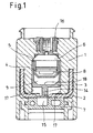
- FIG. 1 shows a separating tool 3 made of plastic reinforced with glass fibers, which is guided in a cylindrical guide 17 of a guide housing 1, which also is molded from fiberglass reinforced plastic.
- the cutting tool 3 has at its end facing a material to be cut 2 a cutting bit 14, which rests against a separation point of the material 2 to be cut.
- the material 2 to be cut is a bus bar. Trapped is the material 2 to be cut through an abutment 7, which in the guide housing 1 is inserted and clamped.
- a striking capsule 4 is pushed, which like the Cutting tool 3 is U-shaped in section and the at its open side a circumferential expansion 5b or two or more (e.g., preferably 2 to 5) bent over Arret istszept 5a has (see Fig. 2).
- the cutting tool 3 has at the open end inside, i. on the inner peripheral wall a corresponding to the radial length and / or the angle of the locking tongues 5 or the expansion 5b beat capsule 4 shaped circumferential phase.
- the striking capsule 4 is included its outer circumferential wall on the inner circumferential wall of the separating tool 3 slidably on. This is a good guide the striking capsule smallest construction volume achieved.
- the pressure pulse generator 6 is ignited electrically, wherein the electrical supply via a plug 16 on the guide housing 1 takes place.
- the on the material to be cut through 2 here the busbar patch cutting tool 3 forms with the impact capsule 4, the pressure pulse generator 6, the guide housing 1 and the anvil 7 a functional unit.
- the pressure pulse generator 6 When the pressure pulse generator 6 is triggered - e.g. by an electrical current pulse from the crash sensor of a car, caused by chemical reaction of the pyrotechnic Materials in the pressure pulse generator a gas pressure, which is in the drive volume 8 and the shock capsule 4 one according to the pressure and the Effect surface resulting impulse imparted. If this impulse exceeds the Holding force of the locking tongues 5a or the expansion 5b, the striking capsule moves 4 with high initial acceleration on the inner shock bottom of the cutting tool 3 too. During the dissolution process of the impact capsule 4 practice the still Not completely bent locking tabs 5a or the expansion 5b a Thrust on the cutting tool 3 through the tubular sleeve. With this Function is a possibly existing, undesirable game between Separating tool 3 and to be cut through material 2 and the busbar removed.
- a further embodiment of the pyrotechnic separation device according to the invention is by the arrangement of a pyrotechnic pressure pulse amplifying element 10 realized on the shock bottom of the cutting tool 3.
- Figures 3 and 4 show two different designs.
- Fig. 3 shows the arrangement of a pyrotechnic Pressure pulse amplifying element 10 without additional ignition device.
- Fig. 4 shows a primer 13 as an ignition device, which in the pressure pulse amplifying element 10 is integrated.
- the striking capsule 4 at her to the shock pad or to the pressure pulse amplifying element 10 end facing a mechanical Schlagzündan extract in the form of a firing pin 11.
- the pressure pulse generator 6 If more power is needed and the pressure pulse generator 6 at its upper Power limit, it allows the pressure pulse amplifying element 10 in the same separator without additional reinforcements or strength enhancement measures To cut through thicker to be cut through materials 2.
- the function of the pressure pulse amplifying element 10 arranged in FIG. 3 is like follows:
- the air in the compression volume 9 is heated so that the pyrotechnic Material in the pressure pulse amplifying element 10 is ignited.
- an absorbent porous Carrier material with pyrotechnic material e.g. a gas kit for airbags, soaked. The amount should be adjusted to the separation task and should not exceed Fill 20% of the compression volume 9.
- FIG. 4 shows a mechanical additional ignition device in the form of an ignition substance pill 13 in the pressure pulse amplifying element 10. It is necessary if the pyrotechnic Material, which represents the pressure pulse amplifying element 10, a very high Ignition temperature or higher ignition energies needed than the adiabatic compression generated. Impact capsule meets 4 with the firing pin 11 on the priming agent 13th auf, which is arranged in the pressure pulse amplifying element 10, the chemical starts Reaction, the pressure pulse amplifying element is ignited and thus a additional pressure pulse generated.
Landscapes
- Engineering & Computer Science (AREA)
- Mechanical Engineering (AREA)
- General Engineering & Computer Science (AREA)
- Air Bags (AREA)
- Percussive Tools And Related Accessories (AREA)
- Processing Of Solid Wastes (AREA)
- Excavating Of Shafts Or Tunnels (AREA)
- Physical Or Chemical Processes And Apparatus (AREA)
- Fuses (AREA)
Abstract
Description
Claims (13)
- Pyrotechnische Trennvorrichtung mit einem Führungsgehäuse (1) in dem ein zu durchtrennendes Teil (2) angeordnet ist, das von einem Trennwerkzeug (3) mit einem Trennmeißel an einer Trennstelle durchtrennbar ausgebildet ist und in der Trennvorrichtung ein eine pyrotechnische Treibladung enthaltener Druckimpulsgenerator (6) zur Generierung eines Druckimpulses zum Antrieb des Trennwerkzeuges (3) angeordnet ist, dadurch gekennzeichnet, dass im Führungsgehäuse (1) eine Schlagkapsel (4) zwischen dem Druckimpulsgenerator (6) und dem Trennwerkzeug (3) angeordnet ist, die durch den Druckimpuls des ausgelösten Druckimpulsgenerators (6) auf einen inneren Stoßboden (18) des Trennwerkzeuges (3) an dem zum Trennmeißel entgegengesetzten Ende des Trennwerkzeuges (3) beschleunigbar ist und dass das Trennwerkzeug (3) mit seinem Trennmeißel vor Auftreffen der Schlagkapsel (4) auf den Stoßboden (18) an der Trennstelle anliegt.
- Trennvorrichtung nach Anspruch 1, dadurch gekennzeichnet, dass das Trennwerkzeug (3) und die Schlagkapsel (4) U-förmig ausgebildet sind und die Schlagkapsel (4) innerhalb des Trennwerkzeuges (3) mit Abstand zum Stoßboden (18) angeordnet ist.
- Trennvorrichtung nach Anspruch 2, dadurch gekennzeichnet, dass die Schlagkapsel (4) mit ihrer äußeren Umfangswandung an der inneren Umfangswandung des Trennwerkzeuges (3) verschiebbar anliegt.
- Trennvorrichtung nach einem der Ansprüche 1 bis 3, dadurch gekennzeichnet, dass zwischen dem Stoßboden (18) und der Schlagkapsel (4) ein Kompressionsvolumen (9) angeordnet ist.
- Trennvorrichtung nach einem der Ansprüche 1 bis 4, dadurch gekennzeichnet, dass die Schlagkapsel (4) und das Trennwerkzeug (3) den Druckimpulsgenerator (6) umgreifen, wobei zwischen dem Druckimpulsgenerator (6) und der Schlagkapsel (4) ein Antriebsvolumen (8) angeordnet ist.
- Trennvorrichtung nach einem der Ansprüche 1 bis 5, dadurch gekennzeichnet, dass die Schlagkapsel (4) an ihrem offenen Ende auf der äußeren Umfangswand eine umlaufende Aufweitung (5b) oder zwei oder mehrere nach Außen umgebogene Arretierungszungen (5a) aufweist und das Trennwerkzeug (3) am offenen Ende innen, d.h. auf der inneren Umfangswand eine entsprechend der Aufweitung (5b) oder der Arretierungszungen (5a) geformte umlaufende Phase aufweist.
- Trennvorrichtung nach einem der Ansprüche 1 bis 6, dadurch gekennzeichnet, dass das Trennwerkzeug (3), die Schlagkapsel (4) und das Führungsgehäuse (1) aus glasfaserverstärktem Kunststoff bestehen.
- Trennvorrichtung nach einem der vorhergehenden Ansprüche, dadurch gekennzeichnet, dass das Massenverhältnis der Schlagkapsel (4) zum Trennwerkzeug (3) bei ca. 1:3 liegt und/oder das Volumenverhältnis des Antriebsvolumens (8) zum Kompressionsvolumen (9) bei ca. 1:3 liegt.
- Trennvorrichtung nach einem der Ansprüche 1 bis 8, dadurch gekennzeichnet, dass auf dem Stoßboden (18) ein pyrotechnisches Druckimpulsverstärkungselement (10) in der Art einer pyrotechnischen Verstärkungsladung aufgebracht ist.
- Trennvorrichtung nach Anspruch 9, dadurch gekennzeichnet, dass im Druckimpulsverstärkungselement (10) eine Zündeinrichtung, bevorzugt eine Zündstoffpille (13) angeordnet ist.
- Trennvorrichtung nach Anspruch 9 oder 10, dadurch gekennzeichnet, dass die Schlagkapsel (4) an der zum Druckimpulsverstärkungselement (10) oder zur Zündeinrichtung gewandten Seite einen Schlagbolzen (11) aufweist.
- Trennvorrichtung nach einem der Ansprüche 1 bis 11, dadurch gekennzeichnet, dass das zu durchtrennende Teil (2) eine Stromschiene ist.
- Trennvorrichtung nach einem der Ansprüche 1 bis 12 zur Verwendung in einer Batterieabschaltung bevorzugt in einem Kraftfahrzeug.
Applications Claiming Priority (4)
| Application Number | Priority Date | Filing Date | Title |
|---|---|---|---|
| DE10334890 | 2003-07-29 | ||
| DE10334890 | 2003-07-29 | ||
| DE102004023415A DE102004023415A1 (de) | 2003-07-29 | 2004-05-12 | Pyrotechnisch angetriebene Trennvorrichtung zum Trennen von massiven, kompakten Materialien |
| DE102004023415 | 2004-05-12 |
Publications (2)
| Publication Number | Publication Date |
|---|---|
| EP1502683A1 true EP1502683A1 (de) | 2005-02-02 |
| EP1502683B1 EP1502683B1 (de) | 2007-09-19 |
Family
ID=33542171
Family Applications (1)
| Application Number | Title | Priority Date | Filing Date |
|---|---|---|---|
| EP04016537A Expired - Lifetime EP1502683B1 (de) | 2003-07-29 | 2004-07-14 | Pyrotechnisch angetriebene Trennvorrichtung zum Trennen von massiven, kompakten Materialien |
Country Status (5)
| Country | Link |
|---|---|
| US (1) | US7182012B2 (de) |
| EP (1) | EP1502683B1 (de) |
| JP (1) | JP4464753B2 (de) |
| AT (1) | ATE373536T1 (de) |
| DE (1) | DE502004004999D1 (de) |
Cited By (2)
| Publication number | Priority date | Publication date | Assignee | Title |
|---|---|---|---|---|
| CN102834889A (zh) * | 2010-03-11 | 2012-12-19 | 自动电缆管理有限责任公司 | 车辆电力线路保险装置 |
| EP2660840A4 (de) * | 2010-12-27 | 2015-01-07 | Daikin Ind Ltd | Schneidegerät |
Families Citing this family (11)
| Publication number | Priority date | Publication date | Assignee | Title |
|---|---|---|---|---|
| DE102007014403B4 (de) * | 2007-03-26 | 2020-02-13 | Trw Airbag Systems Gmbh | Pyrotechnische Antriebseinheit sowie Verfahren zur Herstellung einer solchen Antriebseinheit |
| DE102009037396B4 (de) | 2009-08-13 | 2012-08-16 | Wafios Ag | Pyrotechnisch betätigte Schneidvorrichtung |
| FR2957452B1 (fr) * | 2010-03-15 | 2012-08-31 | Snpe Materiaux Energetiques | Interrupteur electrique a actionnement pyrotechnique |
| CN103854921B (zh) * | 2014-03-14 | 2017-07-07 | 东方久乐汽车安全气囊有限公司 | 碰撞断电保护装置 |
| EP2995822B1 (de) * | 2014-09-09 | 2019-11-13 | Arianegroup Sas | Pyrotechnischer Aktuator |
| JP6406189B2 (ja) * | 2015-09-11 | 2018-10-17 | 豊田合成株式会社 | 導通遮断装置 |
| DE112017002610T5 (de) | 2016-06-30 | 2019-02-21 | Joyson Safety Systems Acquisition Llc | Batterietrennvorrichtung |
| JP6889065B2 (ja) * | 2017-08-18 | 2021-06-18 | 株式会社ダイセル | 発射体の組立体と電気回路遮断装置 |
| CN111750270B (zh) * | 2020-06-30 | 2021-10-15 | 马凌云 | 一种压缩气体自动快速释放装置及使用该装置的救生设备 |
| AT524533B1 (de) | 2021-04-29 | 2022-07-15 | Astotec Automotive Gmbh | Pyrotechnischer Stromtrenner |
| CN116130306A (zh) * | 2021-11-12 | 2023-05-16 | 森萨塔科技(常州)有限公司 | 断路器 |
Citations (5)
| Publication number | Priority date | Publication date | Assignee | Title |
|---|---|---|---|---|
| US4457204A (en) * | 1981-07-21 | 1984-07-03 | Kitz Corporation | Explosive charge-containing nut |
| DE3818669C1 (de) * | 1988-06-01 | 1989-08-24 | Dynamit Nobel Ag, 5210 Troisdorf, De | |
| DE4242014A1 (de) * | 1992-12-12 | 1994-06-23 | Dynamit Nobel Ag | Vorrichtung zum adiabatischen Zünden einer Pulverladung und Kartusche mit adiabatisch zündbarer Pulverladung |
| DE4438157C1 (de) * | 1994-10-26 | 1995-12-07 | Daimler Benz Aerospace Ag | Pyrotechnische Trennvorrichtung |
| DE19732650A1 (de) * | 1997-07-29 | 1999-02-18 | Lell Andrea | Leitungstrenner |
Family Cites Families (10)
| Publication number | Priority date | Publication date | Assignee | Title |
|---|---|---|---|---|
| US3482484A (en) * | 1968-01-22 | 1969-12-09 | Atlas Chem Ind | Cutting tool |
| FR2200770A5 (de) * | 1972-06-26 | 1974-04-19 | France Etat | |
| US3763738A (en) * | 1972-07-03 | 1973-10-09 | Mine Safety Appliances Co | Explosively operated deep water tool |
| US4224487A (en) * | 1978-02-23 | 1980-09-23 | Simonsen Bent P | Fast acting explosive circuit interrupter |
| US4215749A (en) * | 1979-02-05 | 1980-08-05 | Acf Industries, Incorporated | Gate valve for shearing workover lines to permit shutting in of a well |
| JPH0840188A (ja) * | 1994-08-01 | 1996-02-13 | Tokai Rika Co Ltd | 機械着火式センサ |
| DE19503809B4 (de) * | 1995-02-06 | 2005-01-20 | Bayerische Motoren Werke Ag | Sicherungsvorrichtung für eine Stromleitung in Fahrzeugen |
| AU2086397A (en) * | 1996-04-04 | 1997-10-29 | Kabelkonfektion Gebauer & Griller Gmbh | Device for interrupting the flow of current in a cable |
| US6222439B1 (en) * | 1998-02-17 | 2001-04-24 | Sumitomo Wiring Systems, Ltd. | Circuit breaking device |
| US6843157B2 (en) * | 2002-06-13 | 2005-01-18 | Autoliv Asp, Inc. | Severing vehicle battery cable |
-
2004
- 2004-07-14 EP EP04016537A patent/EP1502683B1/de not_active Expired - Lifetime
- 2004-07-14 AT AT04016537T patent/ATE373536T1/de not_active IP Right Cessation
- 2004-07-14 DE DE502004004999T patent/DE502004004999D1/de not_active Expired - Lifetime
- 2004-07-27 JP JP2004218861A patent/JP4464753B2/ja not_active Expired - Fee Related
- 2004-07-29 US US10/901,048 patent/US7182012B2/en not_active Expired - Fee Related
Patent Citations (5)
| Publication number | Priority date | Publication date | Assignee | Title |
|---|---|---|---|---|
| US4457204A (en) * | 1981-07-21 | 1984-07-03 | Kitz Corporation | Explosive charge-containing nut |
| DE3818669C1 (de) * | 1988-06-01 | 1989-08-24 | Dynamit Nobel Ag, 5210 Troisdorf, De | |
| DE4242014A1 (de) * | 1992-12-12 | 1994-06-23 | Dynamit Nobel Ag | Vorrichtung zum adiabatischen Zünden einer Pulverladung und Kartusche mit adiabatisch zündbarer Pulverladung |
| DE4438157C1 (de) * | 1994-10-26 | 1995-12-07 | Daimler Benz Aerospace Ag | Pyrotechnische Trennvorrichtung |
| DE19732650A1 (de) * | 1997-07-29 | 1999-02-18 | Lell Andrea | Leitungstrenner |
Cited By (3)
| Publication number | Priority date | Publication date | Assignee | Title |
|---|---|---|---|---|
| CN102834889A (zh) * | 2010-03-11 | 2012-12-19 | 自动电缆管理有限责任公司 | 车辆电力线路保险装置 |
| CN102834889B (zh) * | 2010-03-11 | 2015-11-25 | 自动电缆管理有限责任公司 | 车辆电力线路保险装置 |
| EP2660840A4 (de) * | 2010-12-27 | 2015-01-07 | Daikin Ind Ltd | Schneidegerät |
Also Published As
| Publication number | Publication date |
|---|---|
| DE502004004999D1 (de) | 2007-10-31 |
| US7182012B2 (en) | 2007-02-27 |
| JP4464753B2 (ja) | 2010-05-19 |
| US20050115390A1 (en) | 2005-06-02 |
| ATE373536T1 (de) | 2007-10-15 |
| EP1502683B1 (de) | 2007-09-19 |
| JP2005049089A (ja) | 2005-02-24 |
Similar Documents
| Publication | Publication Date | Title |
|---|---|---|
| EP1502683B1 (de) | Pyrotechnisch angetriebene Trennvorrichtung zum Trennen von massiven, kompakten Materialien | |
| DE1646330C3 (de) | Feste, zünderlose, gepreßte, durch Schlag zündbare Treibladungstablette | |
| EP0680857B1 (de) | Gasgenerator für ein Fahrzeug-Rückhaltesystem | |
| DE8717582U1 (de) | Aufblasevorrichtung für einen Gassack in einem Fahrzeug | |
| DE60021398T2 (de) | Zünder | |
| EP1492139A1 (de) | Meissel für ein pyromechanisches Trennelement | |
| DE102004023415A1 (de) | Pyrotechnisch angetriebene Trennvorrichtung zum Trennen von massiven, kompakten Materialien | |
| DE2033309A1 (de) | Vorrichtung zum Durchbrechen eines Kanzeldaches eines Flugzeuges | |
| DE102010011150A1 (de) | Sicherung für Kraftfahrzeugenergieleitung | |
| EP1443296B1 (de) | Pyromechanisches Trennelement | |
| EP0882317A1 (de) | Batterie-kabelklemme für fahrzeuge | |
| DE102008027900B4 (de) | Verfahren und Vorrichtung zur Leistungssteuerung eines Gefechtskopfes | |
| DE102019126192B3 (de) | Verfahren und System zum Bereitstellen einer vorbestimmten pyrotechnischen Energieabgabe | |
| CH641555A5 (de) | Geschoss mit einem elektrischen zuender. | |
| EP0790906A1 (de) | Flüssiggasgenerator | |
| DE69106341T2 (de) | Piezoelektrischer zünder. | |
| EP0805071A2 (de) | Vorrichtung zum Aufblasen eines Airbags (III) | |
| DE102008022755A1 (de) | Gasgenerator | |
| DE102015102052B4 (de) | Überrollschutzsystem für Kraftfahrzeuge | |
| EP2776783B9 (de) | Stabilisierungseinrichtung | |
| DE3143899A1 (de) | Verstaerkungsladung | |
| WO2018166720A1 (de) | Zündeinrichtung eines gasgenerators eines airbagmodules für ein kraftfahrzeug | |
| DE102011105508B4 (de) | Vorrichtung und Verfahren zum Betrieb eines Fahrzeuges mit einer Teilmasse | |
| DE112005002942T5 (de) | Sicherheitsvorrichtung für ein Kraftfahrzeug mit einem pyrotechnisch ausgelösten Gas-Mikrogenerator | |
| DE102010054145A1 (de) | Pyrotechnischer Gurtstraffer für einen Sicherheitsgurt eines Kraftfahrzeuges |
Legal Events
| Date | Code | Title | Description |
|---|---|---|---|
| PUAI | Public reference made under article 153(3) epc to a published international application that has entered the european phase |
Free format text: ORIGINAL CODE: 0009012 |
|
| AK | Designated contracting states |
Kind code of ref document: A1 Designated state(s): AT BE BG CH CY CZ DE DK EE ES FI FR GB GR HU IE IT LI LU MC NL PL PT RO SE SI SK TR |
|
| AX | Request for extension of the european patent |
Extension state: AL HR LT LV MK |
|
| RAP1 | Party data changed (applicant data changed or rights of an application transferred) |
Owner name: DELPHI TECHNOLOGIES, INC. |
|
| 17P | Request for examination filed |
Effective date: 20050602 |
|
| AKX | Designation fees paid |
Designated state(s): AT BE BG CH CY CZ DE DK EE ES FI FR GB GR HU IE IT LI LU MC NL PL PT RO SE SI SK TR |
|
| GRAP | Despatch of communication of intention to grant a patent |
Free format text: ORIGINAL CODE: EPIDOSNIGR1 |
|
| GRAS | Grant fee paid |
Free format text: ORIGINAL CODE: EPIDOSNIGR3 |
|
| GRAA | (expected) grant |
Free format text: ORIGINAL CODE: 0009210 |
|
| AK | Designated contracting states |
Kind code of ref document: B1 Designated state(s): AT BE BG CH CY CZ DE DK EE ES FI FR GB GR HU IE IT LI LU MC NL PL PT RO SE SI SK TR |
|
| REG | Reference to a national code |
Ref country code: GB Ref legal event code: FG4D Free format text: NOT ENGLISH |
|
| REG | Reference to a national code |
Ref country code: CH Ref legal event code: EP |
|
| REF | Corresponds to: |
Ref document number: 502004004999 Country of ref document: DE Date of ref document: 20071031 Kind code of ref document: P |
|
| REG | Reference to a national code |
Ref country code: IE Ref legal event code: FG4D Free format text: LANGUAGE OF EP DOCUMENT: GERMAN |
|
| ET | Fr: translation filed | ||
| PG25 | Lapsed in a contracting state [announced via postgrant information from national office to epo] |
Ref country code: FI Free format text: LAPSE BECAUSE OF FAILURE TO SUBMIT A TRANSLATION OF THE DESCRIPTION OR TO PAY THE FEE WITHIN THE PRESCRIBED TIME-LIMIT Effective date: 20070919 |
|
| PG25 | Lapsed in a contracting state [announced via postgrant information from national office to epo] |
Ref country code: PL Free format text: LAPSE BECAUSE OF FAILURE TO SUBMIT A TRANSLATION OF THE DESCRIPTION OR TO PAY THE FEE WITHIN THE PRESCRIBED TIME-LIMIT Effective date: 20070919 |
|
| NLV1 | Nl: lapsed or annulled due to failure to fulfill the requirements of art. 29p and 29m of the patents act | ||
| PG25 | Lapsed in a contracting state [announced via postgrant information from national office to epo] |
Ref country code: ES Free format text: LAPSE BECAUSE OF FAILURE TO SUBMIT A TRANSLATION OF THE DESCRIPTION OR TO PAY THE FEE WITHIN THE PRESCRIBED TIME-LIMIT Effective date: 20071230 Ref country code: GR Free format text: LAPSE BECAUSE OF FAILURE TO SUBMIT A TRANSLATION OF THE DESCRIPTION OR TO PAY THE FEE WITHIN THE PRESCRIBED TIME-LIMIT Effective date: 20071220 Ref country code: NL Free format text: LAPSE BECAUSE OF FAILURE TO SUBMIT A TRANSLATION OF THE DESCRIPTION OR TO PAY THE FEE WITHIN THE PRESCRIBED TIME-LIMIT Effective date: 20070919 |
|
| REG | Reference to a national code |
Ref country code: IE Ref legal event code: FD4D |
|
| PG25 | Lapsed in a contracting state [announced via postgrant information from national office to epo] |
Ref country code: GB Free format text: LAPSE BECAUSE OF FAILURE TO SUBMIT A TRANSLATION OF THE DESCRIPTION OR TO PAY THE FEE WITHIN THE PRESCRIBED TIME-LIMIT Effective date: 20070919 Ref country code: SK Free format text: LAPSE BECAUSE OF FAILURE TO SUBMIT A TRANSLATION OF THE DESCRIPTION OR TO PAY THE FEE WITHIN THE PRESCRIBED TIME-LIMIT Effective date: 20070919 Ref country code: PT Free format text: LAPSE BECAUSE OF FAILURE TO SUBMIT A TRANSLATION OF THE DESCRIPTION OR TO PAY THE FEE WITHIN THE PRESCRIBED TIME-LIMIT Effective date: 20080219 Ref country code: CZ Free format text: LAPSE BECAUSE OF FAILURE TO SUBMIT A TRANSLATION OF THE DESCRIPTION OR TO PAY THE FEE WITHIN THE PRESCRIBED TIME-LIMIT Effective date: 20070919 |
|
| PG25 | Lapsed in a contracting state [announced via postgrant information from national office to epo] |
Ref country code: SE Free format text: LAPSE BECAUSE OF FAILURE TO SUBMIT A TRANSLATION OF THE DESCRIPTION OR TO PAY THE FEE WITHIN THE PRESCRIBED TIME-LIMIT Effective date: 20071219 Ref country code: RO Free format text: LAPSE BECAUSE OF FAILURE TO SUBMIT A TRANSLATION OF THE DESCRIPTION OR TO PAY THE FEE WITHIN THE PRESCRIBED TIME-LIMIT Effective date: 20070919 |
|
| PLBE | No opposition filed within time limit |
Free format text: ORIGINAL CODE: 0009261 |
|
| STAA | Information on the status of an ep patent application or granted ep patent |
Free format text: STATUS: NO OPPOSITION FILED WITHIN TIME LIMIT |
|
| PG25 | Lapsed in a contracting state [announced via postgrant information from national office to epo] |
Ref country code: DK Free format text: LAPSE BECAUSE OF FAILURE TO SUBMIT A TRANSLATION OF THE DESCRIPTION OR TO PAY THE FEE WITHIN THE PRESCRIBED TIME-LIMIT Effective date: 20070919 |
|
| 26N | No opposition filed |
Effective date: 20080620 |
|
| PG25 | Lapsed in a contracting state [announced via postgrant information from national office to epo] |
Ref country code: IE Free format text: LAPSE BECAUSE OF FAILURE TO SUBMIT A TRANSLATION OF THE DESCRIPTION OR TO PAY THE FEE WITHIN THE PRESCRIBED TIME-LIMIT Effective date: 20070919 |
|
| REG | Reference to a national code |
Ref country code: CH Ref legal event code: PL |
|
| PG25 | Lapsed in a contracting state [announced via postgrant information from national office to epo] |
Ref country code: MC Free format text: LAPSE BECAUSE OF NON-PAYMENT OF DUE FEES Effective date: 20080731 |
|
| PG25 | Lapsed in a contracting state [announced via postgrant information from national office to epo] |
Ref country code: EE Free format text: LAPSE BECAUSE OF FAILURE TO SUBMIT A TRANSLATION OF THE DESCRIPTION OR TO PAY THE FEE WITHIN THE PRESCRIBED TIME-LIMIT Effective date: 20070919 |
|
| PG25 | Lapsed in a contracting state [announced via postgrant information from national office to epo] |
Ref country code: LI Free format text: LAPSE BECAUSE OF NON-PAYMENT OF DUE FEES Effective date: 20080731 Ref country code: SI Free format text: LAPSE BECAUSE OF FAILURE TO SUBMIT A TRANSLATION OF THE DESCRIPTION OR TO PAY THE FEE WITHIN THE PRESCRIBED TIME-LIMIT Effective date: 20070919 Ref country code: CH Free format text: LAPSE BECAUSE OF NON-PAYMENT OF DUE FEES Effective date: 20080731 |
|
| PG25 | Lapsed in a contracting state [announced via postgrant information from national office to epo] |
Ref country code: CY Free format text: LAPSE BECAUSE OF FAILURE TO SUBMIT A TRANSLATION OF THE DESCRIPTION OR TO PAY THE FEE WITHIN THE PRESCRIBED TIME-LIMIT Effective date: 20070919 |
|
| PG25 | Lapsed in a contracting state [announced via postgrant information from national office to epo] |
Ref country code: BG Free format text: LAPSE BECAUSE OF FAILURE TO SUBMIT A TRANSLATION OF THE DESCRIPTION OR TO PAY THE FEE WITHIN THE PRESCRIBED TIME-LIMIT Effective date: 20071219 |
|
| PG25 | Lapsed in a contracting state [announced via postgrant information from national office to epo] |
Ref country code: AT Free format text: LAPSE BECAUSE OF NON-PAYMENT OF DUE FEES Effective date: 20080714 |
|
| PG25 | Lapsed in a contracting state [announced via postgrant information from national office to epo] |
Ref country code: BE Free format text: LAPSE BECAUSE OF NON-PAYMENT OF DUE FEES Effective date: 20080731 Ref country code: HU Free format text: LAPSE BECAUSE OF FAILURE TO SUBMIT A TRANSLATION OF THE DESCRIPTION OR TO PAY THE FEE WITHIN THE PRESCRIBED TIME-LIMIT Effective date: 20080320 Ref country code: LU Free format text: LAPSE BECAUSE OF NON-PAYMENT OF DUE FEES Effective date: 20080714 |
|
| PG25 | Lapsed in a contracting state [announced via postgrant information from national office to epo] |
Ref country code: TR Free format text: LAPSE BECAUSE OF FAILURE TO SUBMIT A TRANSLATION OF THE DESCRIPTION OR TO PAY THE FEE WITHIN THE PRESCRIBED TIME-LIMIT Effective date: 20070919 |
|
| REG | Reference to a national code |
Ref country code: FR Ref legal event code: TP Owner name: AUTOLIV DEVELOPMENT AB, SE Effective date: 20120514 |
|
| PGFP | Annual fee paid to national office [announced via postgrant information from national office to epo] |
Ref country code: DE Payment date: 20130520 Year of fee payment: 10 |
|
| PGFP | Annual fee paid to national office [announced via postgrant information from national office to epo] |
Ref country code: FR Payment date: 20130729 Year of fee payment: 10 |
|
| PGFP | Annual fee paid to national office [announced via postgrant information from national office to epo] |
Ref country code: IT Payment date: 20130718 Year of fee payment: 10 |
|
| REG | Reference to a national code |
Ref country code: DE Ref legal event code: R119 Ref document number: 502004004999 Country of ref document: DE |
|
| REG | Reference to a national code |
Ref country code: FR Ref legal event code: ST Effective date: 20150331 |
|
| PG25 | Lapsed in a contracting state [announced via postgrant information from national office to epo] |
Ref country code: IT Free format text: LAPSE BECAUSE OF NON-PAYMENT OF DUE FEES Effective date: 20140714 Ref country code: DE Free format text: LAPSE BECAUSE OF NON-PAYMENT OF DUE FEES Effective date: 20150203 |
|
| REG | Reference to a national code |
Ref country code: DE Ref legal event code: R119 Ref document number: 502004004999 Country of ref document: DE Effective date: 20150203 |
|
| PG25 | Lapsed in a contracting state [announced via postgrant information from national office to epo] |
Ref country code: FR Free format text: LAPSE BECAUSE OF NON-PAYMENT OF DUE FEES Effective date: 20140731 |