EP1501732B1 - Procede pour fabriquer une unite d'emballage et dispositif pour realiser ce procede - Google Patents
Procede pour fabriquer une unite d'emballage et dispositif pour realiser ce procede Download PDFInfo
- Publication number
- EP1501732B1 EP1501732B1 EP03727369A EP03727369A EP1501732B1 EP 1501732 B1 EP1501732 B1 EP 1501732B1 EP 03727369 A EP03727369 A EP 03727369A EP 03727369 A EP03727369 A EP 03727369A EP 1501732 B1 EP1501732 B1 EP 1501732B1
- Authority
- EP
- European Patent Office
- Prior art keywords
- pile
- envelope
- stack
- insulation boards
- compression
- Prior art date
- Legal status (The legal status is an assumption and is not a legal conclusion. Google has not performed a legal analysis and makes no representation as to the accuracy of the status listed.)
- Expired - Lifetime
Links
- 238000004806 packaging method and process Methods 0.000 title claims abstract description 64
- 238000000034 method Methods 0.000 title claims abstract description 56
- 238000004519 manufacturing process Methods 0.000 title claims abstract description 21
- 239000011490 mineral wool Substances 0.000 claims abstract description 24
- 239000000463 material Substances 0.000 claims abstract description 17
- 239000011230 binding agent Substances 0.000 claims abstract description 16
- 239000011491 glass wool Substances 0.000 claims abstract description 15
- 229910052500 inorganic mineral Inorganic materials 0.000 claims abstract 3
- 239000011707 mineral Substances 0.000 claims abstract 3
- 238000009413 insulation Methods 0.000 claims description 97
- 238000007906 compression Methods 0.000 claims description 68
- 230000006835 compression Effects 0.000 claims description 67
- 238000010438 heat treatment Methods 0.000 claims description 37
- 238000003466 welding Methods 0.000 claims description 30
- 230000008569 process Effects 0.000 claims description 16
- 238000001816 cooling Methods 0.000 claims description 14
- 230000006837 decompression Effects 0.000 claims description 13
- XLYOFNOQVPJJNP-UHFFFAOYSA-N water Substances O XLYOFNOQVPJJNP-UHFFFAOYSA-N 0.000 claims description 12
- -1 polytetrafluorethylene Polymers 0.000 claims description 10
- VYPSYNLAJGMNEJ-UHFFFAOYSA-N Silicium dioxide Chemical compound O=[Si]=O VYPSYNLAJGMNEJ-UHFFFAOYSA-N 0.000 claims description 8
- 229910052751 metal Inorganic materials 0.000 claims description 7
- 239000002184 metal Substances 0.000 claims description 7
- 239000003595 mist Substances 0.000 claims description 6
- 238000003825 pressing Methods 0.000 claims description 5
- CURLTUGMZLYLDI-UHFFFAOYSA-N Carbon dioxide Chemical compound O=C=O CURLTUGMZLYLDI-UHFFFAOYSA-N 0.000 claims description 4
- 230000036961 partial effect Effects 0.000 claims description 3
- 229920003023 plastic Polymers 0.000 claims description 3
- 239000004033 plastic Substances 0.000 claims description 3
- 230000005855 radiation Effects 0.000 claims description 3
- 235000011089 carbon dioxide Nutrition 0.000 claims description 2
- 239000002826 coolant Substances 0.000 claims description 2
- 229920001296 polysiloxane Polymers 0.000 claims description 2
- 229920001343 polytetrafluoroethylene Polymers 0.000 claims description 2
- 239000011248 coating agent Substances 0.000 claims 1
- 238000000576 coating method Methods 0.000 claims 1
- 150000001875 compounds Chemical class 0.000 claims 1
- 239000011810 insulating material Substances 0.000 abstract description 14
- 239000000835 fiber Substances 0.000 abstract description 5
- 239000002985 plastic film Substances 0.000 description 76
- 229920006255 plastic film Polymers 0.000 description 75
- 239000002557 mineral fiber Substances 0.000 description 57
- 238000006243 chemical reaction Methods 0.000 description 14
- 239000012774 insulation material Substances 0.000 description 9
- 239000004698 Polyethylene Substances 0.000 description 8
- 239000000155 melt Substances 0.000 description 8
- 239000010410 layer Substances 0.000 description 6
- 229920000573 polyethylene Polymers 0.000 description 6
- 230000007704 transition Effects 0.000 description 6
- VGGSQFUCUMXWEO-UHFFFAOYSA-N Ethene Chemical compound C=C VGGSQFUCUMXWEO-UHFFFAOYSA-N 0.000 description 5
- 230000002829 reductive effect Effects 0.000 description 5
- 230000006378 damage Effects 0.000 description 4
- 239000004702 low-density polyethylene Substances 0.000 description 4
- 239000000203 mixture Substances 0.000 description 4
- 238000007639 printing Methods 0.000 description 4
- 229920006300 shrink film Polymers 0.000 description 4
- 238000013459 approach Methods 0.000 description 3
- 230000008901 benefit Effects 0.000 description 3
- 230000015572 biosynthetic process Effects 0.000 description 3
- 238000005336 cracking Methods 0.000 description 3
- 229920001684 low density polyethylene Polymers 0.000 description 3
- 239000002245 particle Substances 0.000 description 3
- 238000006116 polymerization reaction Methods 0.000 description 3
- 230000009467 reduction Effects 0.000 description 3
- 238000012546 transfer Methods 0.000 description 3
- 210000002268 wool Anatomy 0.000 description 3
- 230000037303 wrinkles Effects 0.000 description 3
- 239000005977 Ethylene Substances 0.000 description 2
- 239000004743 Polypropylene Substances 0.000 description 2
- 229920001577 copolymer Polymers 0.000 description 2
- 238000009826 distribution Methods 0.000 description 2
- 230000000694 effects Effects 0.000 description 2
- 239000013013 elastic material Substances 0.000 description 2
- 230000007613 environmental effect Effects 0.000 description 2
- 239000011888 foil Substances 0.000 description 2
- 239000008187 granular material Substances 0.000 description 2
- 239000004700 high-density polyethylene Substances 0.000 description 2
- 230000002427 irreversible effect Effects 0.000 description 2
- 229920000092 linear low density polyethylene Polymers 0.000 description 2
- 239000004707 linear low-density polyethylene Substances 0.000 description 2
- 229920000098 polyolefin Polymers 0.000 description 2
- 229920001155 polypropylene Polymers 0.000 description 2
- 239000010453 quartz Substances 0.000 description 2
- 238000000926 separation method Methods 0.000 description 2
- 239000003238 silicate melt Substances 0.000 description 2
- 239000002893 slag Substances 0.000 description 2
- 244000025254 Cannabis sativa Species 0.000 description 1
- 235000012766 Cannabis sativa ssp. sativa var. sativa Nutrition 0.000 description 1
- 235000012765 Cannabis sativa ssp. sativa var. spontanea Nutrition 0.000 description 1
- 235000008733 Citrus aurantifolia Nutrition 0.000 description 1
- 235000013162 Cocos nucifera Nutrition 0.000 description 1
- 244000060011 Cocos nucifera Species 0.000 description 1
- 235000004431 Linum usitatissimum Nutrition 0.000 description 1
- 240000006240 Linum usitatissimum Species 0.000 description 1
- 229920002367 Polyisobutene Polymers 0.000 description 1
- 229910000831 Steel Inorganic materials 0.000 description 1
- 239000004809 Teflon Substances 0.000 description 1
- 229920006362 Teflon® Polymers 0.000 description 1
- 235000011941 Tilia x europaea Nutrition 0.000 description 1
- 229920001807 Urea-formaldehyde Polymers 0.000 description 1
- XTXRWKRVRITETP-UHFFFAOYSA-N Vinyl acetate Chemical compound CC(=O)OC=C XTXRWKRVRITETP-UHFFFAOYSA-N 0.000 description 1
- 206010047571 Visual impairment Diseases 0.000 description 1
- 239000006096 absorbing agent Substances 0.000 description 1
- 238000007792 addition Methods 0.000 description 1
- 239000000443 aerosol Substances 0.000 description 1
- 239000003513 alkali Substances 0.000 description 1
- 229910000272 alkali metal oxide Inorganic materials 0.000 description 1
- 239000003963 antioxidant agent Substances 0.000 description 1
- 244000052616 bacterial pathogen Species 0.000 description 1
- 239000002585 base Substances 0.000 description 1
- 238000005452 bending Methods 0.000 description 1
- 229910052810 boron oxide Inorganic materials 0.000 description 1
- 230000001680 brushing effect Effects 0.000 description 1
- 238000009435 building construction Methods 0.000 description 1
- 230000009172 bursting Effects 0.000 description 1
- 235000009120 camo Nutrition 0.000 description 1
- 235000005607 chanvre indien Nutrition 0.000 description 1
- 238000005253 cladding Methods 0.000 description 1
- 239000003086 colorant Substances 0.000 description 1
- 230000000295 complement effect Effects 0.000 description 1
- 239000002131 composite material Substances 0.000 description 1
- 239000012141 concentrate Substances 0.000 description 1
- 239000000470 constituent Substances 0.000 description 1
- 238000010276 construction Methods 0.000 description 1
- 230000008602 contraction Effects 0.000 description 1
- 238000007334 copolymerization reaction Methods 0.000 description 1
- 230000000881 depressing effect Effects 0.000 description 1
- 238000013461 design Methods 0.000 description 1
- 238000001514 detection method Methods 0.000 description 1
- 238000011161 development Methods 0.000 description 1
- 238000002845 discoloration Methods 0.000 description 1
- 229910000514 dolomite Inorganic materials 0.000 description 1
- 239000010459 dolomite Substances 0.000 description 1
- 238000001704 evaporation Methods 0.000 description 1
- 230000008020 evaporation Effects 0.000 description 1
- 239000003365 glass fiber Substances 0.000 description 1
- 230000005484 gravity Effects 0.000 description 1
- 239000011487 hemp Substances 0.000 description 1
- 229920001903 high density polyethylene Polymers 0.000 description 1
- 229940063583 high-density polyethylene Drugs 0.000 description 1
- 238000003780 insertion Methods 0.000 description 1
- 230000037431 insertion Effects 0.000 description 1
- UQSXHKLRYXJYBZ-UHFFFAOYSA-N iron oxide Inorganic materials [Fe]=O UQSXHKLRYXJYBZ-UHFFFAOYSA-N 0.000 description 1
- 235000013980 iron oxide Nutrition 0.000 description 1
- VBMVTYDPPZVILR-UHFFFAOYSA-N iron(2+);oxygen(2-) Chemical class [O-2].[Fe+2] VBMVTYDPPZVILR-UHFFFAOYSA-N 0.000 description 1
- 239000002655 kraft paper Substances 0.000 description 1
- 238000003475 lamination Methods 0.000 description 1
- 239000004571 lime Substances 0.000 description 1
- 229920004889 linear high-density polyethylene Polymers 0.000 description 1
- 239000007788 liquid Substances 0.000 description 1
- 229940099514 low-density polyethylene Drugs 0.000 description 1
- 239000000314 lubricant Substances 0.000 description 1
- 230000007246 mechanism Effects 0.000 description 1
- 239000004745 nonwoven fabric Substances 0.000 description 1
- MOWNZPNSYMGTMD-UHFFFAOYSA-N oxidoboron Chemical class O=[B] MOWNZPNSYMGTMD-UHFFFAOYSA-N 0.000 description 1
- TWNQGVIAIRXVLR-UHFFFAOYSA-N oxo(oxoalumanyloxy)alumane Chemical compound O=[Al]O[Al]=O TWNQGVIAIRXVLR-UHFFFAOYSA-N 0.000 description 1
- 239000005022 packaging material Substances 0.000 description 1
- 230000000149 penetrating effect Effects 0.000 description 1
- 238000006068 polycondensation reaction Methods 0.000 description 1
- 229920000728 polyester Polymers 0.000 description 1
- 229920000306 polymethylpentene Polymers 0.000 description 1
- 239000011116 polymethylpentene Substances 0.000 description 1
- 239000004810 polytetrafluoroethylene Substances 0.000 description 1
- 239000002244 precipitate Substances 0.000 description 1
- 230000002028 premature Effects 0.000 description 1
- 238000004886 process control Methods 0.000 description 1
- 230000001737 promoting effect Effects 0.000 description 1
- 239000002994 raw material Substances 0.000 description 1
- 230000035484 reaction time Effects 0.000 description 1
- 230000008707 rearrangement Effects 0.000 description 1
- 238000011084 recovery Methods 0.000 description 1
- 238000004064 recycling Methods 0.000 description 1
- 229920005989 resin Polymers 0.000 description 1
- 239000011347 resin Substances 0.000 description 1
- 230000000284 resting effect Effects 0.000 description 1
- 230000000717 retained effect Effects 0.000 description 1
- 238000007363 ring formation reaction Methods 0.000 description 1
- 239000011435 rock Substances 0.000 description 1
- 239000002356 single layer Substances 0.000 description 1
- 241000894007 species Species 0.000 description 1
- 239000012798 spherical particle Substances 0.000 description 1
- 239000010959 steel Substances 0.000 description 1
- 230000008961 swelling Effects 0.000 description 1
- 229920002994 synthetic fiber Polymers 0.000 description 1
- 239000012209 synthetic fiber Substances 0.000 description 1
- 230000002123 temporal effect Effects 0.000 description 1
- 229920001169 thermoplastic Polymers 0.000 description 1
- 229920001187 thermosetting polymer Polymers 0.000 description 1
- 239000004416 thermosoftening plastic Substances 0.000 description 1
- 230000036962 time dependent Effects 0.000 description 1
- 208000029257 vision disease Diseases 0.000 description 1
- 230000004393 visual impairment Effects 0.000 description 1
- 239000002699 waste material Substances 0.000 description 1
Images


Classifications
-
- B—PERFORMING OPERATIONS; TRANSPORTING
- B65—CONVEYING; PACKING; STORING; HANDLING THIN OR FILAMENTARY MATERIAL
- B65B—MACHINES, APPARATUS OR DEVICES FOR, OR METHODS OF, PACKAGING ARTICLES OR MATERIALS; UNPACKING
- B65B63/00—Auxiliary devices, not otherwise provided for, for operating on articles or materials to be packaged
- B65B63/02—Auxiliary devices, not otherwise provided for, for operating on articles or materials to be packaged for compressing or compacting articles or materials prior to wrapping or insertion in containers or receptacles
- B65B63/026—Auxiliary devices, not otherwise provided for, for operating on articles or materials to be packaged for compressing or compacting articles or materials prior to wrapping or insertion in containers or receptacles for compressing by feeding articles through a narrowing space
-
- B—PERFORMING OPERATIONS; TRANSPORTING
- B65—CONVEYING; PACKING; STORING; HANDLING THIN OR FILAMENTARY MATERIAL
- B65B—MACHINES, APPARATUS OR DEVICES FOR, OR METHODS OF, PACKAGING ARTICLES OR MATERIALS; UNPACKING
- B65B53/00—Shrinking wrappers, containers, or container covers during or after packaging
- B65B53/02—Shrinking wrappers, containers, or container covers during or after packaging by heat
- B65B53/06—Shrinking wrappers, containers, or container covers during or after packaging by heat supplied by gases, e.g. hot-air jets
- B65B53/063—Tunnels
-
- B—PERFORMING OPERATIONS; TRANSPORTING
- B65—CONVEYING; PACKING; STORING; HANDLING THIN OR FILAMENTARY MATERIAL
- B65B—MACHINES, APPARATUS OR DEVICES FOR, OR METHODS OF, PACKAGING ARTICLES OR MATERIALS; UNPACKING
- B65B2220/00—Specific aspects of the packaging operation
- B65B2220/24—Cooling filled packages
Definitions
- the invention relates to a method for producing a packaging and / or transport unit, consisting of a stack with a plurality of at least two insulating panels of at least limited elastic material, in particular bound with binders mineral fibers, preferably rock wool and / or glass wool, wherein the insulation panels of an endless nonwoven fabric separated, arranged with their large surfaces adjacent to each other in the stack and then with at least one stack at least partially surrounding, shrinking under heat envelope, preferably provided in the form of a film and / or at least one band and an apparatus for performing the method ,
- Natural fibers such as wool, flax, coconut, hemp, synthetic fibers, such as polyester fibers or man-made glass fibers are suitable for the production of sheet-like or plate-like insulating materials for thermal and / or acoustic insulation.
- Mineral wool insulation materials represent the most significant group of fiber insulation materials in terms of quantity.
- the mineral wool insulating materials are differentiated into glass wool and rock wool insulating materials.
- Glass wool insulating materials are made from silicate melts with high levels of alkali and boron oxides. These melts can be withdrawn through nozzles to mineral fibers, these nozzles being arranged in walls of bowl-shaped and rotationally driven fiberizing devices.
- the mineral fibers are usually impregnated with an organic binder, primarily a mixture of phenol-urea-formaldehyde resins.
- the mineral fibers produced in this method of manufacture are relatively long and smooth and are collected underneath the fiberizing device on a collecting and conveying belt. The mineral fibers are piled up at a desired height and transported continuously with the conveyor belt as a mineral fiber mass.
- This type of lamination of a continuous mineral fiber fleece formed from the mineral fiber mass is generally referred to as direct collection. Since the efficiency of the shredders used with several hundred kilograms of mineral fibers per hour is not so high, several shredders are usually placed one after the other on a production line, that is a collection and conveyor belt.
- the bulk density of the mineral fiber fleece is adjusted as a function of the conveying speed of the endless mass flow of fibers.
- This mineral fiber fleece is then fed to a hardening furnace in which the thermosetting binders mentioned by way of example are cured and the mineral fiber fleece is fixed.
- hot air is sucked through the permeable mineral fiber fleece, so that the intensive energy transfer leads to rapid curing of the binder.
- the insulating felts and insulation panels made of glass wool have in common an extremely layered structure parallel to their large surfaces. This structure leads to a low thermal conductivity and a high ductility perpendicular to the large surfaces. In contrast, the connection between the individual mineral fibers is perpendicular to their longitudinal axis, so the transverse tensile strength of the structure very low. Parallel to the large surfaces, the stiffness of the insulating felts and insulating panels is much higher, regardless of the direction of loading.
- Insulation felts made from glass wool can be rolled up easily and with a high degree of compression of up to approx. 60% without tearing and largely regain the original thickness.
- This type of treatment is counteracted by the fact that the thickness tolerances for the type of application WL in accordance with DIN 18165 Part 1 allow significantly greater thicknesses than are the case for application type W insulation panels.
- the Dämmfilze can therefore be prepared with a relatively large excess thickness to compensate for strength losses and then compressed.
- Glass wool insulation boards must not be compressed as much as possible in order not to fall out of a permissible thickness tolerance field. Since the degrees of compression are not tuned steplessly, but in connection with usual packaging units or bulk, packaging or transport units and in relation to the volumes, in particular the height of the means of transport (truck, railway wagon), compression rates of about 20% already contribute the packaging units at significant cost savings.
- Rock wool insulation materials are produced from silicate melts that are rich in alkaline earths, iron oxides and, as network formers, contain not inconsiderable amounts of aluminum oxide.
- Rock wool insulation materials were originally produced only from diabase and chemically related basalts with small amounts of lime or dolomite.
- the raw material blends contain high proportions of suitable residues from the production of other materials and accumulating waste materials from the production or recycling of mineral fiber insulation materials.
- the previously produced metallurgical wool consisted mostly of blast-furnace slags and small additions of quartz-containing rocks. Blast furnace slags are also processed today in the production of rockwool insulation materials. The independent species of cottage wool is no longer available in this country.
- the melt for the production of rock wool insulating materials has a very steep dependence of the viscosity on the temperature, so that only a narrow temperature interval for mineral fiber formation is available.
- the melt is processed in the majority of factories on so-called cascade shredding machines. These machines usually have four staggered rollers rotating about horizontal axes. The melt is passed in a thin layer successively over the rollers. Depending on the speed of rotation, the presence of germs and temperature, liquid bodies, which assume either spherical or fibrous form, as well as other intermediate forms, first dissolve out of the melt. In this way, about 50% by mass of useful mineral fibers can be recovered from the melt.
- the other half of the melt goes into spherical to stem-like particles, which are separated by air classification of the mineral fiber mass. Nevertheless, about 25 to 30% by weight of spherical particles remain in the mineral fiber mass.
- the fiberizing machines with up to about 5 tons throughput per hour, are considerably more efficient than the fiberizing devices used for the production of glass wool.
- the mineral fibers of rockwool are bound with binders, which are dissolved or colloidally distributed in water as in the production of glass wool.
- binders which are dissolved or colloidally distributed in water as in the production of glass wool.
- the individual mineral fibers of rock wool are much shorter than the mineral fibers of glass wool.
- the rock wool mineral fibers are curved in themselves and get caught in the air stream easily with each other, forming more or less large flakes.
- the rock wool mineral fibers can be picked up directly.
- a production plant with high performance it is not possible to achieve a completely homogeneous distribution of the mineral fibers over the length, width and height of a mineral fiber fleece to be produced.
- an endless mineral fiber mass flow must either be cooled by large amounts of water or the polycondensation reaction of the resin mixtures used continues to run, resulting in premature curing of the binder.
- the removal of the water is associated with a high energy demand and thus uneconomical. All of these negative aspects have led to the fact that the mineral fibers impregnated with binders are deposited on a conveyor belt in a thin primary web and transported away.
- This primary web is now placed meandering transversely to the conveying direction of a further conveyor belt on this second conveyor belt by means of a pendulum device.
- a pendulum device for example 2 or 4 m and its basis weight, for example about 300 to about 800 g / m 2 , are in the primary nonwoven formed secondary mineral fiber layer about 4 to about 12 layers obliquely and respectively offset by the pendulum stroke.
- the primary nonwoven layers in the secondary mineral fiber fleece are on the one hand in the horizontal direction quite easily, and on the other, and this particular compressed in the vertical direction.
- the secondary mineral fiber fleece is compressed more strongly in the longitudinal as well as in the vertical direction. there The individual mineral fibers are brought in a steep position to the large surfaces of the secondary mineral fiber fleece and at the same time significantly increases the bulk density of the mineral fiber mass.
- the curing of the binder takes place in the rock wool insulating materials in analogy to the glass wool insulating materials by means of hot air in a curing oven.
- the lower limit of the gross density of rock wool insulation boards is currently about 24 kg / m 3 , which corresponds to about 15 - 17 kg mineral fibers / m 3 .
- the upper limit of the insulation boards produced in the manner described is approximately at about 55 kg / m 3 (38.5 kg mineral fibers / m 3 ).
- the mineral fiber equivalents are given here as essential elements of presentation, because the unbound non-fibrous constituents only marginally or not at all affect the mechanical properties relevant here in the first place.
- the endless sheet-like mineral fiber fleece is usually split longitudinally in the longitudinal direction and separated the insulation panels in the desired width of the partial webs.
- a different approach can be chosen.
- Glass wool insulating materials can also be produced in single layers with small thicknesses.
- the endless mineral fiber fleece is already separated on the production line horizontally in two to four layers
- a separated from the mineral fiber fleece insulation board therefore has in their longitudinal direction a significantly higher stiffness and bending tensile strength than transversely to its longitudinal direction.
- the rock wool insulation boards can therefore be compressed only with significantly higher power input and develop due to the higher spring constant of the mineral fiber mass also a correspondingly high counter or restoring force. Excessive deformation also risks causing the mineral fibers to break, relocate or destroy the bonds between the mineral fibers. In this case, irreversible structural changes can occur. Since the deforming forces attack primarily at right angles to the large surfaces, either the desired nominal thickness is no longer achieved or when releasing large voltages this nominal thickness is exceeded in an inadmissible manner.
- the separated insulation boards are, if necessary freed from adhering sawdust and arranged in a stack one above the other or after a rotation next to each other or stacked.
- the height of the stack is limited by the weight of the insulating panels and by the still manageable size of a packaging unit formed from the stack. Therefore, stack heights of about 20 cm to about 60 cm are usual, but preferably the height is limited to less than about 50 cm.
- the stack of insulating panels is wrapped with films and / or banding, which hold the stack together and against environmental influences, such as moisture protect. Furthermore, the films and / or bands are used to handle the packaging unit.
- foils those made of polyolefins, such as polyethylene and copolymers with, for example, ethylene and vinyl acetate or polypropylene because of their material properties, especially their good shrinkage properties, the comparatively high shrinkage forces at room temperature and other advantages in the application and not least because of their low price have proven particularly.
- Polyethylene is formed by the polymerization of ethylene.
- high-pressure polymerization branched polyethylenes of low to medium density are primarily formed (low-density poly-ethylene, abbreviation LDPE).
- Very low densities are found in the LLDPE types polyethylenes.
- the so-called low-pressure polymerization results predominantly in linear high-density polyethylenes (high-density poly-ethylene, abbreviation HDPE).
- the copolymerization with other unsaturated components allows the development of plastics with special properties.
- EP 1 050 466 A1 distinguishes between polyethylene film (PE film) and polyolefin film (PO film).
- the PE films are used in this prior art in thicknesses of about 25 to about 250 microns, the PO films with thicknesses of about 8 microns to 35 microns, but especially from 15 microns to about 19 microns.
- Shrink films are usually made by the blow and the chill-roll process of granules.
- the granules contain, inter alia, lubricant concentrates, colorants, antioxidants and UV absorbers.
- the films are stretched in a second operation, usually even biaxially, to reduce the thickness to the desired level and by the orientation of the molecular chains by external force an increase in the strength in this To reach direction. While maintaining the tensile forces, the O-orientation state is fixed by cooling. Relatively high elastic components, which lead to residual stresses, are to be retained. These internal restoring forces lead at higher temperatures to the desired here fast recovery, ie shrinking. With the biaxial stretching, the strength values in the longitudinal and in the transverse direction can be adjusted in a targeted manner.
- the shrinkage force is that force which is exerted on a specimen by it during and after exposure to heat, when it is clamped at two ends so that it can not be shortened.
- the maximum heat shrinkage which is determined at a certain temperature and after cooling to room temperature.
- specific shrinkage forces which are time-dependent.
- stress relaxation Another important property of shrinkable films is stress relaxation, which indicates the temporal decay of stress in a deformed material, if this deformation is kept constant.
- the stack of insulation boards is fed on a conveyor belt a banding and provided with a sheath.
- banding for other objects are in the already mentioned EP 1 050 466 A1 and EP 718 198 A1.
- banding shrink film rolls are located above and below a conveyor plane. Plastic film sheets drawn from the shrink-film rolls are brought together and joined together by a weld. They thereby form a foil curtain.
- Corresponding banding stations are also in the production of packaging units from each stack of insulation boards in use.
- the stack of insulation boards is conveyed against this film curtain, wherein the film webs are tracked. Then the promotion is stopped.
- a beam arranged above the conveying plane of a welding press is moved against a lower beam arranged, for example, in the conveying plane.
- the jaws are coated with Teflon to prevent the films from sticking.
- thermoplastic films are heated to plastic flow and joined together under pressure.
- the welding changes the structure of the interconnected plastic films. Only really good weld seams almost reach the breaking strength of the base materials.
- shrink films are preferably used, which consist of LDPE or mixtures of LLDPE and LDPE.
- the thicknesses of the plastic films are reduced to about 20 microns to about 100 microns, preferably about 35 microns to about 65 microns.
- the heat impulse welding is preferred.
- the heating elements are heated by power surges, which are matched to the type and thickness of the films to be joined, in no time.
- Double beams are used, which produce two parallel welds. The two film webs are severed between the beams or the welds with the aid of an interposed filament. The upper bar is moved back to the rest position.
- the band is significantly wider than the stack of insulation panels.
- the overhang on each face of the stack of insulation boards may be a few inches or reach well over half the height of the stack of insulation boards. Because of the resilience of the insulation panels and the shrinkage of the band will avoid a flush or slightly over-wide band. Otherwise, there is a risk that the insulation panels at the ends of the packaging unit circumferentially slip out of the band, which would primarily lead to a visual impairment.
- the over the faces of the stack projecting film sections hang down and lie on the conveyor belt.
- the stack of insulating panels with the envelope made of plastic film is then fed to a shrink tunnel, as it can be found for example in EP 1 050 466 A1, US Pat. No. 6,151,871 A1 or EP 1 044 883 A1.
- the heating of the plastic films by means of heated air, which is brought to the surfaces of the stack of insulation boards.
- the height of the air temperature is adjusted according to the throughput through the shrink tunnel and the thickness of the plastic films.
- a typical temperature range is, for example, between about 130 and 170 ° C.
- the banded stack of insulation boards is for this purpose on a good air-permeable conveyor belt, which consists for example of spaced-mounted metal rods or a wire mesh. The spaced-mounted thin metal rods hinder the contraction of the films little.
- the plastic films After the shrinking process, the plastic films have been tightly applied to the surfaces of the insulation panels of the stack and hold this stack together. Since the friction coefficient of the insulating panels is very high, thin plastic films with low shrinkage force at room temperature are sufficient to secure the insulation panels against slipping within the stack.
- the shrinking process also changes the position of the welds previously produced between the film webs. They are now each in the lower third of the two side surfaces of the stack.
- the air duct in the shrink tunnel is formed so that the overhanging at the end faces of the stack plastic films are bent to the center of each end face and welded together in this position.
- the heating can be more intense here than in the region of the side surfaces of the stack, in order to achieve a partial welding or a stronger shrinkage.
- the plastic films attach themselves to the stack of insulation boards and thus stabilize it also in the longitudinal direction.
- the thicker and firmer film areas on the end faces due to the shrinking also allow intervention here with the hands and the handling of the packaging unit.
- the enclosure often also has openings as a result of differential heating or obstructed shrinkage.
- the wrapper can tear through hard insulation panels at the edges or in the region of the welds. The reason for this is from the outset imperfect welds, but also the heating of the seams twice. On closer examination, there are also significant deformations of the plastic films or discoloration of colored plastic films in a range of about 10 to about 20 mm on both sides of the welds to recognize.
- a material thickness of the plastic film in the initial state of about 63 microns to about 64 microns is obtained after shrinking a substantially uniform thickness of about 63 microns, so that the differences in thickness are within the accuracy of a micrometer. In areas immediately adjacent to the weld seams, however, the thicknesses are only about 50 ⁇ m.
- the invention is based on the object, a method of claim 1 for producing a packaging and / or transport unit consisting of a stack with several, at least two insulating panels of at least limited elastic material in such a way that the disadvantages of the prior art be avoided, in particular to achieve a simpler process to improve the stability of the envelope and to protect the insulation panels.
- the solution of this task provides, in a method according to the invention, that the stack of insulating panels in the envelope is compressed before shrinking the envelope in a compressed stack.
- the stack of insulating panels is compressed prior to application of the plastic film as a wrapper and then subjected to the enclosure in the compressed state of heating, which serves to shrink the plastic film.
- the stack of insulating panels is first covered with the plastic film and then compressed and finally supplied to the heating in the compressed state.
- the welds or the surface areas of the plastic film with the welds are cooled down quickly, for example, with air, CO 2 vapor (dry ice), finely sprayed water or an alternative cooling medium. This is intended to prevent these surface areas from being heated more strongly in the subsequent shrinking process and thus from shrinking more than the plastic film in the area of the further surface areas, in particular in the region of the side surfaces and / or end faces of the stack.
- the plastic films can be shrunk to a greater extent in the area of the two end faces of the stack than in the area of the large surfaces of the stack of insulation boards.
- the envelope can be closed or partially open in the region of the end faces of the stack.
- the packaging units are supplied in succession to a compression station with integrated decompression device with the intervals resulting from the cycle times of the banding station. At least this area of a device according to the invention is arranged to avoid environmental influences on the result of the shrinkage of the plastic film in a housing.
- the packaging units Prior to the entry of the packaging units in the compression station, the packaging units are rotated by 90 degrees and positioned so that the packaging units run into the compression station with one of their front faces.
- This approach reduces the risk of the insulation panels tearing in one of their large surfaces with a steep increase in compression.
- the compression station consists of a lower and an upper conveyor belt, which are spaced from each other in the housing. The distance between the conveyor belts is adjustable.
- the pressure-exerting conveyors with inclinations between about 1.5% and well compressible insulation boards are also up 4% arranged converging.
- the upper conveyor belt is arranged inclined from its horizontal orientation to the opposite conveyor belt.
- the inclination angle is made larger, so that there is a tendency between about 4 and 8%.
- the conveyor belt can be adjusted to each other in terms of their inclination to adjust different compression in different insulation panels can.
- the conveyor belts consist of inherently pressure-resistant elements, for example plastic sheets stiffened with metal rods or of trough-shaped metal members.
- the conveyor belts are coated with, for example, polytetrafluoroethylene, silicone or the like in order to prevent sticking of the plastic films to the conveyor belts.
- the insulation boards in the packaging unit are significantly more compressed than the desired degree of compression in the finished packaging unit.
- This increase in compression can be up to about 50% and is limited only by the fact that irreversible damage to the structure of the insulating panels are to be avoided. This compression can effectively complement a previous elastification of the individual insulation panels.
- these portions are heated to continue the shrinking operation.
- the heating of the plastic films is done in such a way that the furthest bulge areas are heated the most.
- the heating of the plastic films takes place, for example, with electrically heated coils or quartz rods with different heating powers over the length of the compression station.
- the radiators equipped with reflectors can be rigidly arranged or pivoted up and down in regular movements.
- the distribution of hot air can be supported by fans.
- the heating of the plastic film surfaces with hot air which is heated outside the housing and directed by nozzles targeted at the surfaces to be heated of the plastic film.
- the flow velocity may vary over the length of the stack of insulation boards to be treated. Normally, the flow velocity is so low that the plastic films are not pressed on the insulating panels. With a sharper flow, the plastic films can also be set in a flapping motion to keep them free from de surfaces of the insulation boards. With the help of the nozzles, the plastic films can be blown with different levels of heated hot air.
- dry hot steam can be used.
- the heating can be continued until the highest compression or before completion of sufficient heating of the plastic films.
- the compression station can be followed by a reaction zone in which the packaging unit is held with the last degree of compression, so that the shrinkage process starts evenly. This process can be controlled by a uniform temperature of the space surrounding the packaging unit.
- the compressed packaging unit is transported to a decompression station, in which the compression of the insulation boards is gradually released.
- Decompression can be faster than compression.
- the side surfaces of the stack are optionally zonar or selectively cooled in sequence with hot air, room or compressed air or a water mist.
- the packaging units produced in this way generally result in uneven shrinkage over the circumference of the packaging units. This also results in an increase in the material thickness of the over the side surfaces of the stack most shrunken plastic film to, for example, about 180 to 200 microns, while the material thickness of the plastic film on the top and bottom of the stack is about 80 to 90 microns.
- transition region there is a risk of tearing the stretched plastic film by an abrupt increase in the material thickness of the plastic film.
- a gradual increase in material thickness should be strived for or the abrupt increase in material thickness should be avoided.
- the transition region should moreover be arranged at a distance from an adjacent edge of the stack of insulation boards, since a linear clamping point of the plastic film lies in the edge region and consequently the strongest strains can occur.
- the distance between the shrinkage-related transition region of different material thicknesses of the plastic film regions from the edge of the stack should therefore be more than about 2 cm. This distance may preferably be formed by the targeted heating, possibly with a supplementary cooling of the edge zones of the transition region.
- angle elements or diaphragms can be provided, for example, on the conveyor belts in the compression station and / or shrinking station, wherein the angle elements or diaphragms with the conveyor belts pass through the shrinking station. A complete shielding of the side surfaces is not useful to achieve even transitions.
- the edges of the angle elements or diaphragms can be wavy.
- the vertical edges of the packaging units may also prove to be sensitive to cracks since here clamping points form between the plastic films, which have previously shrunk to a greater extent on the end faces, and now remain unchanged zones. In principle, this cracking can be counteracted in a corresponding manner.
- a band may also be provided, the welds of which are arranged on the upper and lower cover surfaces of the stack. This arrangement of the welds is possible if the insulation panels are previously placed upright against each other and then surrounded with the enclosure. Also in this case, the stack is previously rotated 90 degrees and either held laterally or pressed together in the longitudinal direction until the banderole is applied.
- the band is pre-shrunk as described above in this case before the insulation boards are compressed and fed in the compressed state of the shrinking station. At the latest before the compression device further rotation of the packaged and provided with a preshrunk banderole or wrapping stack insulation boards is done by 90 degrees, so that the stack resumes its initial position.
- the end faces of the packaging units are not shrunk.
- shrinking the plastic film regions projecting in the area of the end faces can be prevented, for example, by pressing these plastic film regions against the heat during the pre-shrinking and / or the shrinking process by means of vertically arranged laterally arranged side strips.
- This procedure leads to a banderole that is open at least after the pre-shrinkage, so that the plastic film in the shrinking station can be uniformly heated over the entire length of the packaging unit and consequently shrinks accordingly uniformly.
- the tensile stresses and thus the risk of cracking in the plastic film are reduced, whereby the use of thinner plastic films is possible, which leads to a reduction in packaging costs and the cost of disposal of packaging materials on construction sites.
- the heating of the plastic films can also be done with the aid of a preferably spirally moving laser steel.
- a device which has a banding station in which a stack of a plurality of insulating plates arranged one above the other or side by side, in particular of mineral fibers, with at least one under heat shrinkage film.
- this device has a compression station in which the stack surrounding the film is compressed at least in the direction of the surface normal of the large surfaces of the insulating panels and / or in the direction perpendicular to the surface normal of the large surfaces of the insulating panels.
- a shrinking station in which the film is shrunk in a compressed stack such that the film rests, in particular, over a whole area on at least part of the outer surfaces of the stack.
- film webs are welded together in the banding station by means of at least one welding bar to form a film curtain, against which the stack of insulating boards is conveyed.
- a film curtain By promoting the stack of insulation boards of the film curtain is disposed at the top and bottom of the stack and finally connected to the advancing side surface opposite side surface of the stack by another welding process with the welding bar to a sheath, which is then separated from the film webs.
- the film webs are guided by suitable, for example convex deflection rollers and / or brush rollers with symmetrical, outwardly directed spiral arrangement of the bristles, so that on the one hand the withdrawal resistance of corresponding supply rolls is reduced and on the other hand largely caused by the train Querfalten Strukturen in the film sections substantially , At the same time the tension is reduced, which is caused by the current against the film curtain stack of insulation boards.
- a retractable stop in the conveying path can be provided, on which the insulating plates of the stack or the stack are aligned before the stack is banded.
- the stop can be intermittently inserted or pushed out into the conveying path.
- the Stop arranged in the region of the film curtain, so that the film curtain between stop and stack is arranged.
- a spring-mounted pulley or running at low speed counter to the direction of flow brushing roller is provided, which presses the film curtain on the rear side surface of the stack of insulation boards with lowering welding bar.
- the deflection roller or brush roller can be supplemented by a second roller or a pressure plate.
- the wrapper or banderole produced in this way fits snugly against the stack of insulating panels. It follows that a preshrunk process now to be performed can be performed with less energy and in less time. In addition, due to the close concern of the plastic film to the stack insulation boards, a thinner plastic film can be used, which can be shrunk by lower energies in the subsequent shrinkage process.
- the welding bar cooperates with an abutment which is arranged in the plane of a lower conveyor belt in order to form the welds to be executed as far down as possible, ie in the area of the lowest insulation board of the stack. Both welds are thus in the range the lowest insulation board of the pile. Subsequent pre-shrink pulls the welds upward from this original position.
- the positioning of the welds can of course also be such that the front weld is placed as always in the region of the conveying plane and the rear weld, but this requires that the abutment for the welding bar is transferred to an upper position in which the Weld is formed.
- stacking of insulation boards requires such an approach accurate detection of the dimensions of the stack and a correspondingly complex process control.
- a loose band is produced in the usual form.
- the stack of insulation boards is held laterally by two acting on the end faces of the stack pressure plates, which are occupied, for example, penetrating into the insulation board pin.
- the front weld is positioned slightly elevated above the feed plane.
- the conveying direction is changed, so that the conveyor belt feeds the banderole under the stack of insulating boards. If the weld initially lying in the conveying direction lies below the stack, the conveyor belt is stopped. At this time, the second, originally located behind the seam in the front area of the upper large surface of the top insulation board in the stack.
- the return transport of the band can be supported by suction nozzles, which are guided over the surface of the band.
- the stack can be raised for this purpose but also by means of the side plates described above.
- a cooling device for the weld is provided in the region of the welding bar, wherein the cooling device promotes in particular cold air, water mist and / or CO 2 vapor to the weld. This is to prevent the already preheated Areas of the plastic film with the weld in the subsequent shrinking station to be heated too much and shrunk.
- the packaging unit is heated to a greater extent in the region of its underside resting on the conveyor belt, so that both weld seams provided in the area of the lowest insulation board are drawn into this area due to the greater shrinkage of the film in the area of the underside and in subsequent shrinkage processes are not more thermally stressed.
- the packaging unit thus formed is aligned longitudinally and fed to a compression station with integrated decompression device.
- this compression station the banded stack of insulation boards is compressed and guided decompressed to elasticize the insulation boards.
- This compression can either be done in a previously described compression station with two spaced conveyor belts or run with a stamp that touches the surface of the stack insulation boards and this compressed and then selectively decompressed. Alternatively, the compression can also be carried out between two stamps which can be moved toward one another. In the stamp conveyor belts can be integrated, which perform the insertion and ejection of a stack of insulation boards. Subsequently, the stack passes insulation boards while maintaining the last compression in the shrinking station, in which the envelope or band is shrunk snugly.
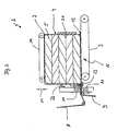
- FIG. 1 shows a banding and shrinking station 2, 17 of a device 1 for producing a packaging and / or transport unit 16 from a stack 4 of a plurality of insulating panels 5.
- This device 1 is known from the prior art.
- the banding station 2 consists of a two consecutively arranged conveyor belt sections having lower conveyor belt 3 for conveying the stack 4 of several insulation boards 5 in the direction of an arrow 6.
- the stack 4 is surrounded in the banding station 2 with a sheath 7, on the two side surfaces and the Surface and the lower surface of the stack 4 and thus the insulation boards 5 rests.
- the enclosure consists of two welded together plastic film webs 8 and 9, which are deducted by film coils not shown.
- the two plastic film webs 8 and 9 form a film curtain arranged between the conveyor belt sections, against which the stack 4 is conveyed by means of the first conveyor belt section of the conveyor belt 3.
- the plastic film webs 8 and 9 are welded together a second time, so that the Plastic film webs 8 and 9 forming the four surfaces of the stack 4 adjacent closed enclosure 7.
- the device 1 in the region of the banding station 2 a welding bar 10 which is movable in the direction of the arrows 11.
- an abutment 12 for the welding bar 10 is arranged in the conveying plane of the conveyor belt 3.
- Welding beam 10 and abutment 12 are each U-shaped, wherein in the free ends of the legs of the welding bar 10, the corresponding devices for forming welds 13 are arranged, with which the welds 13 than over the entire width of the plastic film webs 8, 9 extending be formed linear junctions.
- a separation device is provided, with the enclosure 7 after formation of the welds 13 of the film curtain, consisting of the plastic film webs 8 and 9 is separated.
- the separator may be formed, for example, as a heated metal wire.
- the banding station 2 has an upper conveyor belt 14, which on the one hand serves to convey the stack 4 and on the other hand presses the upper plastic film web 8 against the stack 4.
- the conveyor belt 14 is arranged according to the arrow 15 in its distance from the lower conveyor belt 3 adjustable.
- the thus formed packaging unit 16 is fed to a shrinking station 17 having a heat-insulated housing 18 in which a conveyor belt 19 is arranged ,
- the conveyor belt 19 consists of individual air-permeable chain links 20th
- a temperature is generated by means of known heat sources, such as infrared radiators or the like, in which the sheath 7 shrinks and fits snugly against the insulating panels 5.
- the packaging unit 16 is conveyed out of the shrinking station 17 and fed to the shipping after cooling.
- the stations in the device 1 shown in FIGS. 2 to 5 are distinguished by the following improvements according to the invention:
- a stop 21 is additionally provided, which can be retracted or moved out of the conveying path.
- the stop 21 serves to align the stack 4 before closing the wrapper 7 and at the same time pressing the plastic film web 8 against the side face of the stack 4 lying in the conveying direction.
- the welding bar 10 has, on its surface facing the conveyor belt 3 or the stack 4, a first upper roller 22 and a second lower, spring-loaded roller 23, which together act on the plastic film web 8 in the area of the side surface opposite the conveying surface in the conveying direction abut the stack 4 and press there the plastic film web 8 to the stack 4 to form already during the welding of the two plastic film web 8 and 9 to close the envelope 7 a fully applied to the corresponding surfaces of the stack 4 enclosure 7.
- the roller 22 is spring-mounted to ensure a constant concern with the stack 4.
- the stop 21 is moved out of the conveying path and the packaging unit 16 is moved by means of the conveyor belts 3 and 14 of a compression mechanism shown in FIGS. and shrinking station 24, 30 fed.
- the packaging units 16 are rotated by 90 ° before the compression and shrinking station 24, 30, so that the packaging units 16 with an end face of the stack 4 advances in the compression and shrinking station 24, 30.
- the side surfaces of the stack 4 extending transversely to the conveying direction in the banding station 2 thus run parallel to the conveying direction in the compression and shrinking stations 24, 30.
- the compression station 24 consists of an upper pressure belt 25 and a lower pressure belt 26, wherein the compression station 24 is divided into a compression zone 27, a reaction zone 28 and a decompression zone 29.
- the pressure belts 25, 26 are formed such that the distance between the pressure belts 25, 26 is reduced and the incoming there insulation boards 5 are compressed in the stack 4 together with the enclosure 7.
- the reaction zone 28 connects, in which the pressure belts 25, 26 have a constant distance from each other and in which the stack 4 of the insulating panels 5 is held with the last degree of compression of the compression zone 27.
- the shrinkage of the envelope 7 takes place.
- heat sources not shown in greater detail are provided in FIG. 3, which heat up at least the reaction zone 28 to a temperature required for a shrinkage of the envelope 7.
- the length of the reaction zone 28 corresponds at least to the length of a packaging unit 16.
- the length of the reaction zone 28 is important insofar as it is to be avoided to decompress one part of the packaging unit 16 while another part of the packaging unit 16 is still being compressed. The decompression can be done much faster than the compression.
- a cooling station 39 (FIG. 4) may be provided, with which the preshrunk envelope 7 is cooled, in order to end a possibly still continuing shrinking process.
- the side surfaces, ie running parallel to the conveying direction Areas of the packaging unit 16 zonar selectively cooled with room or compressed air or a water mist.
- the reaction zone 28 thus also contains the shrinking station 30.
- the packaging unit 16 enters the decompression zone 29, in which the packaging unit 16 is decompressed in a controlled manner.
- This controlled decompression is particularly advantageous for such insulating panels 5, which have a relatively high restoring force. It should be noted that the insulation panels 5 are compressed beyond the required extent. In the decompression zone 29, the swelling of the insulating panels 5 can then be canceled at low speed, without suddenly occurring tensile stresses leading to an expansion of the envelope 7, which may lead to a tearing of the envelope 7 in their edge regions.
- the shrinking station 30 following in the compression station 24 to the compression zone 27 and shown in plan view in Figure 4 has a plurality of hot air nozzles 31 which are connected via corresponding connecting lines 32 with fans 33 therein to a central heating system 34 with a burner 35.
- the envelope 7 is first slightly heated in the region of the side surfaces of the stack 4 in order to soften the envelope 7. This heating takes place in the entry region of the shrinking station 30 at the beginning of the reaction zone 28.
- the shrinking station 30 has four parallel connecting lines in the region of the heating system 34 with the burner 35.
- the warm air nozzles 31 are arranged, with which warm air is blown onto the side surfaces of the packaging units 16.
- suction nozzles 36 are arranged, which are also connected to parallel to the connecting lines 32 extending connecting lines 37 and a fan 38.
- the fan 38 the warm air, which was previously blown from the hot air nozzles 31 on the side surface of the packaging unit 16, sucked again, in order to perform here only a heating and softening of the sheath 7.
- the envelope 7 is then heated via two adjacent warm air nozzles 31 and shrunk to the desired level.
- the packaging unit 16 passes through the cooling station 39, in which the packaging units 16 are cooled in a controlled manner via corresponding cold air nozzles 40.
- the embodiment of a shrinking station 30 shown in FIG. 4 can be connected several times in series within the compression zone 27 and the reaction zone 28.
- the generation of hot air can be done with different hot air nozzles 31. These may be individually heated or connected to a central heating system 34. Due to the design of the printing belts 25, 26 as permeable conveyor belts, the excess warm air can escape upwards and / or downwards and be sucked out there.
- the arrangement of the warm air nozzles 31 described above is provided on both sides of the printing belts 25, 26. The same applies to the alternative heat sources described below. Of course, combinations of the heat sources on one or both sides of the printing belts 25, 26 are possible.
- the infrared radiators 41 shown in FIG. 4 may be provided alone or in addition to convection hot air devices.
- the devices for heating the envelope 7 may be arranged rigidly, displaceable along the spatial axes and / or be rotatable about the spatial axes.
- the heating of the side surfaces of the envelope 7 is differentiated over the length of the system, as well as the height of the packaging units 16. It is a so-called gradient heating.
- non-shrunk or slightly shrunken areas of the envelope 7 can be made with panels that cover the corresponding areas in the heating of the enclosure 7.
- the diaphragms may also be designed as angle pieces and in particular with wavy edges, so that the cracks resulting from a possible bursting of the cooled casing 7 can not be extended unhindered along this transition area.
- the bulging of the envelope 7 and the shrinkage of the envelope 7 run synchronously to shorten the reaction times. In principle, it is of course also possible to start the shrinking process only when the final degree of compression of the stack 4 of the insulating panels 5 is reached, so that the shrinkage is limited to the reaction zone 28.
- a gradual heating of the surfaces of the envelope 7 can also be done with quartz glass emitters, on the back of heating wires are printed.
- the printed heating wires are electrically heated and can, for example be arranged between two quartz glass panes.
- Such quartz glass emitters not only have the advantage of a very accurate control, but they also effect an energy transfer in all three ways, ie by heat conduction in direct contact, by radiation and by convection.
- the heating can be continued until the highest compression or after sufficient heating of the films previously terminated.
- the quartz glass emitters can also be used with suction nozzles, which attract the sheath 7 to the quartz glass emitters.
- the end faces of the packaging units 16 are shrunk in a further shrinking station 42.
- a corresponding shrinking station 42 is shown in FIG. 5 and adjoins the shrinking station 30, which is designed in FIG. 5 with an alternative fitting of the heat radiators in comparison to FIG.
- the shrinking station 42 has a conveyor belt 43 which runs at right angles to the pressure belts 25, 26 according to FIG. 3 and adjoins them.
- the packaging units 16 removed from the shrinking station 30 are thus deflected from their original conveying direction into a conveying direction running at right angles thereto, without their longitudinal axis orientation being changed.
- the packaging units 16 reach the area of a warm air station 44 with two hot air nozzles 45 arranged opposite one another, which blow hot air onto the end faces of the stack 4 and the sections of the envelope 7 which have not yet been shrunk there.
- the packaging units 16 are supplied to a cooling air station 46 with two cold air nozzles 47, which blow cold air onto the envelope 7 in the region of the end faces of the stack 4 in order to cool the sections of the envelope 7 shrunk there.
- the cold air nozzles 47 are also like the hot air nozzles 45 opposite each other arranged so that both end surfaces can be cooled simultaneously. In this area too, gradient heating is advantageous, with which parts of the packaging unit 16 can be heated more strongly.
Landscapes
- Engineering & Computer Science (AREA)
- Mechanical Engineering (AREA)
- Auxiliary Devices For And Details Of Packaging Control (AREA)
- Basic Packing Technique (AREA)
- Supplying Of Containers To The Packaging Station (AREA)
- Laminated Bodies (AREA)
- Wrapping Of Specific Fragile Articles (AREA)
Claims (34)
- Procédé de fabrication d'une unité d'emballage et/ou de transport constituée par une pile (4) avec plusieurs, au moins deux panneaux de matériau isolant (5) en un matériau élastique au moins de manière limitée, en particulier en fibres minérales liées avec des liants, de préférence en laine minérale et/ou en laine de verre, pour lequel les panneaux de matériau isolant sont séparés d'un non-tissé sans fin, placés dans la pile avec leurs grandes surfaces l'une contre l'autre et sont ensuite pourvus d'au moins une enveloppe (7) qui entoure la pile au moins partiellement, qui rétrécit sous l'effet de la chaleur, de préférence en forme de feuille et/ou au moins d'une banderole,
caractérisé en ce
que la pile (4) des panneaux de matériau isolant (5) est comprimée dans l'enveloppe (7) avant que l'enveloppe (7) soit rétrécie dans la pile comprimée. - Procédé selon la revendication 1,
caractérisé en ce
que les panneaux de matériau isolant sont comprimés individuellement et/ou dans la pile avant et/ou après leur mise en place dans l'enveloppe et ensuite décomprimés de manière guidée. - Procédé selon la revendication 1,
caractérisé en ce
que l'enveloppe est formée par deux moitiés d'une feuille qui sont en particulier soudées l'une à l'autre dans la zone parallèlement à l'axe longidutinal des panneaux de matériau isolant. - Procédé selon la revendication 1,
caractérisé en ce
que l'enveloppe est constituée par une feuille en plusieurs couches, en particulier par une feuille composite. - Procédé selon la revendication 3,
caractérisé en ce que les cordons de soudure sont refroidis avec un agent de refroidissement, par exemple de l'air, de la vapeur de CO2 (glace sèche) et/ou de l'eau. - Procédé selon la revendication 1,
caractérisé en ce
que l'enveloppe est plus fortement rétrécie dans des zones partielles, en particulier dans la zone des faces frontales de la pile, que par exemple dans la zone des surfaces latérales et/ou des grandes surfaces de la pile. - Procédé selon la revendication 1,
caractérisé en ce
que l'enveloppe est fermée dans la zone des faces frontales de la pile. - Procédé selon la revendication 1,
caractérisé en ce
que la pile est comprimée avec l'enveloppe avant l'opération de rétrécissement, est ensuite décomprimée de manière guidée et est finalement comprimée avant l'opération de rétrécissement. - Procédé selon la revendication 1,
caractérisé en ce
que les panneaux de matériau isolant sont séparés du non-tissé en fibres transversalement par rapport à l'extension longitudinale et sont tournés de 90° avant d'entrer dans un dispositif de compression. - Procédé selon la revendication 9,
caractérisé en ce
que la compression des panneaux de matériau isolant est réalisée dans leur sens longitudinal. - Procédé selon la revendication 1,
caractérisé en ce
que la pile des panneaux de matériau isolant est plus fortement comprimée que le degré de compression souhaité de l'unité d'emballage et/ou de transport. - Procédé selon la revendication 11,
caractérisé en ce
que le degré de compression de l'unité d'emballage et/ou de transport dans la pile des panneaux de matériau isolant avant l'opération de rétrécissement est dépassé jusqu'à 50%. - Procédé selon la revendication 1,
caractérisé en ce
que l'enveloppe est chargée pendant l'opération de rétrécissement avec de l'air chaud et/ou de la vapeur chaude sèche. - Procédé selon la revendication 1,
caractérisé en ce
que la compression de la pile est agrandie pendant l'opération de rétrécissement. - Procédé selon la revendication 1,
caractérisé en ce
que la compression de la pile après l'opération de rétrécissement est maintenue de préférence pendant une phase de refroidissement de l'enveloppe. - Procédé selon la revendication 15,
caractérisé en ce
que la phase de refroidissement est réalisée à une température constante. - Procédé selon la revendication 1,
caractérisé en ce
que la pile est décomprimée de manière guidée après l'opération de rétrécissement. - Procédé selon la revendication 17,
caractérisé en ce
que la décompression de la pile est réalisée en un temps plus court que la compression de la pile. - Procédé selon la revendication 17,
caractérisé en ce
que l'enveloppe est refroidie en particulier dans la zone des faces latérales de la pile pendant la décompression, de préférence avec de l'air chaud, de l'air comprimé et/ou un brouillard d'eau. - Procédé selon la revendication 1,
caractérisé en ce
que les panneaux de matériau isolant sont posés dans la pile avant l'enveloppe avec au moins une banderole sur leurs faces latérales dans le sens longitudinal et que la banderole est soudée dans la zone au moins d'une grande surface d'un panneau de matériau isolant placé à l'extérieur dans la pile. - Dispositif pour réaliser le procédé selon l'une des revendications 1 à 20, avec un poste d'application de banderoles (2) dans laquelle une pile (4) de plusieurs panneaux de matériau isolant (5) placés l'un sur l'autre ou l'un à côté de l'autre, en particulier en fibres minérales, est entourée avec au moins une enveloppe (7) qui rétrécit sous l'effet de la chaleur, un poste de compression dans lequel la pile (4) entourée avec l'enveloppe (7) est comprimée au moins en direction de la normale des grandes surfaces des panneaux de matériau isolant (5) et/ou dans le sens à angle droit par rapport à la normale des grandes surfaces des panneaux de matériau isolant (5) et d'un poste de rétrécissement (30, 42) dans lequel l'enveloppe (7) est rétrécie, la pile (4) étant comprimée, de manière telle que l'enveloppe (7) repose en particulier globalement en surface sur au moins une partie des surfaces extérieures de la pile (4).
- Dispositif selon la revendication 21,
caractérisé en ce
que le poste d'application des banderoles (2) présente une butée (21) transversalement au sens de transport sur laquelle les panneaux de matériau isolant (5) de la pile (4) et/ou des piles (4) sont alignés. - Dispositif selon la revendication 21,
caractérisé en ce
que le poste d'application des banderoles (2) a au moins une mâchoire d'appareil à souder (10) avec lequel les deux extrémités d'une banderole qui forme l'enveloppe (7) sont soudées l'une à l'autre et qu'il est prévu, dans la zone de la mâchoire d'appareil à souder (10), un rouleau de pression positionné de préférence à ressort, un cylindre à brosse et/ou une plaque de pression qui appuie l'enveloppe (7) avant ou pendant le processus de soudure contre la pile (4). - Dispositif selon la revendication 23,
caractérisé en ce
qu'il est prévu un dispositif de refroidissement pour le cordon de soudure (13) dans la zone de la mâchoire d'appareil à souder (10), le dispositif de refroidissement transportant en particulier de l'air froid, du brouillard d'eau et/ou de la vapeur de CO2 sur le cordon de soudure. - Dispositif selon la revendication 21,
caractérisé en ce
que le poste d'application des banderoles (2) présente des éléments de recouvrement qui recouvrent les faces frontales de la pile (4) sur deux côtés d'une bande de transport (3) qui transporte la pile (4), par exemple des bandes latérales, qui empêchent une amorce de rétrécissement des sections de l'enveloppe (7) qui font saillie au-delà des faces frontales de la pile (4). - Dispositif selon la revendication 21,
caractérisé en ce
que le poste de compression (24) présente au moins une zone de décompression (29) dans laquelle la pile (4) placée dans l'enveloppe (7) est décomprimée de manière contrôlée de préférence entre deux zones de compression (27). - Dispositif selon la revendication 21,
caractérisé en ce
que le poste de compression (24) présente au moins une bande de compression, de préférence deux bandes de compression (25, 26) qui vont l'une vers l'autre. - Dispositif selon la revendication 27,
caractérisé en ce
que les bandes de compression (25, 26) sont inclinées l'une vers l'autre avec une inclinaison entre 1,5 et 8 %. - Dispositif selon la revendication 21,
caractérisé en ce
que le poste de compression (24) présente un appui et un piston de compression placé au-dessus ou deux pistons de compression placés l'un en face de l'autre qui sont suivis par deux bandes de transport placées espacées et parallèles l'une à l'autre dont l'écart est de préférence réglable. - Dispositif selon la revendication 27 ou 29,
caractérisé en ce
que les bandes de compression (25, 26) sont constituées par des éléments en métal de préférence en forme d'auge ou par des éléments en plastique rigides à la pression qui sont rigidifiés en particulier avec des tiges en métal. - Dispositif selon la revendication 27 ou 29,
caractérisé en ce
que les surfaces des bandes de compression (25, 26) sont configurées non adhésives et ont par exemple une enduction en silicone ou en polytétrafluoréthylène. - Dispositif selon la revendication 21,
caractérisé en ce
que le poste de rétrécissement (30, 42) présente des dispositifs de chauffage au-dessus et au-dessous de la pile qui traverse (4). - Dispositif selon la revendication 32,
caractérisé en ce
que des températures qui diffèrent sont réglables dans le poste de rétrécisseemnt (30, 42) par l'écart entre le dispositif de chauffage supérieur et le dispositif de chauffage inférieur si bien que par exemple la face inférieure de la pile (4) est plus fortement réchauffée que la face supérieure de la pile (4). - Dispositif selon la revendication 32,
caractérisé en ce
que les dispositifs de chauffage sont configurés comme des tuyères d'air chaud (31, 45), des diffuseurs à infrarouge (41) et/ou des diffuseurs à verre de quartz.
Applications Claiming Priority (3)
| Application Number | Priority Date | Filing Date | Title |
|---|---|---|---|
| DE10219174 | 2002-04-30 | ||
| DE10219174 | 2002-04-30 | ||
| PCT/EP2003/004352 WO2003093114A1 (fr) | 2002-04-30 | 2003-04-25 | Procede pour fabriquer une unite d'emballage et dispositif pour realiser ce procede |
Publications (3)
| Publication Number | Publication Date |
|---|---|
| EP1501732A1 EP1501732A1 (fr) | 2005-02-02 |
| EP1501732B1 true EP1501732B1 (fr) | 2006-06-07 |
| EP1501732B2 EP1501732B2 (fr) | 2010-07-28 |
Family
ID=29285039
Family Applications (1)
| Application Number | Title | Priority Date | Filing Date |
|---|---|---|---|
| EP03727369A Expired - Lifetime EP1501732B2 (fr) | 2002-04-30 | 2003-04-25 | Procede pour fabriquer une unite d'emballage et dispositif pour realiser ce procede |
Country Status (5)
| Country | Link |
|---|---|
| EP (1) | EP1501732B2 (fr) |
| AT (1) | ATE328798T1 (fr) |
| AU (1) | AU2003233071A1 (fr) |
| DE (2) | DE10392088D2 (fr) |
| WO (1) | WO2003093114A1 (fr) |
Families Citing this family (12)
| Publication number | Priority date | Publication date | Assignee | Title |
|---|---|---|---|---|
| WO2010024660A1 (fr) * | 2008-08-27 | 2010-03-04 | Doeka Asia Sdn. Bhd. | Dispositif de séparation et d’emballage de produits élastiques |
| EP2256043A1 (fr) * | 2009-05-28 | 2010-12-01 | Seelen A/S | Tuyau de sortie en quatre morceaux |
| EP2256044A1 (fr) * | 2009-05-29 | 2010-12-01 | Seelen A/S | Plaque de compression |
| FI124460B (sv) * | 2009-08-25 | 2014-09-15 | Paroc Group Oy | Förpackning och/eller transportenhet för isolerskivor av mineralull samt förfarande och anordning för tillverkning av sådana |
| DE102010012597A1 (de) * | 2010-03-24 | 2011-09-29 | Multivac Sepp Haggenmüller Gmbh & Co. Kg | Einrichtung zum Transportieren von Objekten |
| DE102011052101B4 (de) | 2011-07-25 | 2023-10-05 | Krones Aktiengesellschaft | Schrumpfvorrichtung mit Gebindekühlung |
| CN206609273U (zh) * | 2014-04-09 | 2017-11-03 | 克朗斯股份公司 | 具有包捆物冷却设备的收缩装置 |
| TWI655136B (zh) * | 2014-06-27 | 2019-04-01 | 日商養樂多本社股份有限公司 | Shrinking label heat shrinking device |
| WO2017210734A1 (fr) * | 2016-06-08 | 2017-12-14 | Enviro Bale Pty Ltd | Système d'ensachage pour l'ensachage de balles de matériau comprimé et procédé d'ensachage de matériau comprimé avec ledit système d'ensachage |
| EP3725693A1 (fr) * | 2019-04-18 | 2020-10-21 | Herbert Bailer GmbH | Dispositif et procédé de production d'un élément isolant emballé dans une feuille imprimée |
| US11932437B2 (en) * | 2021-12-29 | 2024-03-19 | Tony Tateossian | Method of shaping and compressing toilet paper rolls |
| CN120922431B (zh) * | 2025-10-09 | 2026-01-27 | 交城义望铁合金节能环保科技有限责任公司 | 一种矿棉板预制模块生产热缩膜封装系统 |
Family Cites Families (6)
| Publication number | Priority date | Publication date | Assignee | Title |
|---|---|---|---|---|
| US3362128A (en) † | 1965-02-12 | 1968-01-09 | Hayssen Mfg Company | Method of packaging articles |
| US3958392A (en) * | 1973-12-05 | 1976-05-25 | H. G. Weber And Company, Inc. | Method and apparatus for heat shrinking film about articles |
| FR2510515B1 (fr) † | 1981-07-31 | 1985-12-06 | Saint Gobain Isover | Procede pour le conditionnement de panneaux d'un materiau compressible et conditionnements realises par ce procede |
| DE4005541A1 (de) * | 1990-02-22 | 1991-08-29 | Rockwool Int | Verfahren und vorrichtung zum komprimieren und verpacken von platten oder rollen aus mineralwolle |
| US5339605B1 (en) * | 1993-03-11 | 1998-08-04 | Signature Packaging Machinery | Product compression for shrink tunnel |
| FR2771375A1 (fr) * | 1997-11-25 | 1999-05-28 | Saint Gobain Isover | Procede et dispositif de conditionnement de materiaux compressibles |
-
2003
- 2003-04-25 WO PCT/EP2003/004352 patent/WO2003093114A1/fr not_active Ceased
- 2003-04-25 EP EP03727369A patent/EP1501732B2/fr not_active Expired - Lifetime
- 2003-04-25 AT AT03727369T patent/ATE328798T1/de active
- 2003-04-25 DE DE10392088T patent/DE10392088D2/de not_active Expired - Fee Related
- 2003-04-25 AU AU2003233071A patent/AU2003233071A1/en not_active Abandoned
- 2003-04-25 DE DE50303703T patent/DE50303703D1/de not_active Expired - Lifetime
Also Published As
| Publication number | Publication date |
|---|---|
| ATE328798T1 (de) | 2006-06-15 |
| EP1501732A1 (fr) | 2005-02-02 |
| EP1501732B2 (fr) | 2010-07-28 |
| WO2003093114A1 (fr) | 2003-11-13 |
| AU2003233071A1 (en) | 2003-11-17 |
| DE10392088D2 (de) | 2005-06-09 |
| DE50303703D1 (de) | 2006-07-20 |
Similar Documents
| Publication | Publication Date | Title |
|---|---|---|
| EP1501732B1 (fr) | Procede pour fabriquer une unite d'emballage et dispositif pour realiser ce procede | |
| DE69530181T2 (de) | Isolierelement und verfahren und vorrichtung zur herstellung und zum verpacken | |
| AT408426B (de) | Verfahren zum kontinuierlichen herstellen von gegenständen aus einem folienumhüllten kern | |
| DE3701592C2 (fr) | ||
| DE69632778T2 (de) | Herstellung einer mehrschichtfolie für verpackungen | |
| DE69812230T2 (de) | Verfahren und vorrichtung zur herstellung von verbundplatten | |
| US4349325A (en) | Apparatus for manufacturing plastic products | |
| DE60002419T2 (de) | Verfahren zur herstellung eines aus faserverstärktem thermoplastischem harz geformten produktes und dadurch hergestelltes produkt | |
| DE102017131026A1 (de) | Verbesserte Quertrennschweißeinrichtung, Folienverpackungsmaschine und Verfahren | |
| DE4405120A1 (de) | Verfahren und Vorrichtung zum Verpacken von Preßballen sowie Packmittelzuschnitt | |
| DE102020106030B4 (de) | Längstrennschweißeinrichtung für eine Verpackungsmaschine und Verfahren zum Verpacken eines Packguts mit einer aus einer oberen Papierbahn und einer unteren Papierbahn erzeugten Umverpackung | |
| DE60038213T2 (de) | Isolationsmaterial und dessen herstellungsverfahren | |
| DE102020106025B4 (de) | Verpackungsmaschine und Verfahren zum Verpacken eines Packguts mit einer aus einer oberen Papierbahn und einer unteren Papierbahn erzeugten Umverpackung | |
| DE4005541A1 (de) | Verfahren und vorrichtung zum komprimieren und verpacken von platten oder rollen aus mineralwolle | |
| DE2239204A1 (de) | Schichtstoff sowie verfahren und vorrichtung zu seiner herstellung | |
| EP1390262B1 (fr) | Procede de realisation d'une unite d'emballage et/ou de transport pour materiaux isolants en forme de plaques constitues de fibres minerales, unite d'emballage et/ou de transport, et plaque de materiau isolant | |
| EP1321382A1 (fr) | Conditionnement de plusieurs rouleaux d'isolant à base de laine minérale emballés individuellement sous film | |
| KR102148085B1 (ko) | 헌 합성섬유와 타 공된 박판 또는 헌 합성섬유와 거물형망을 이용한 친환경 고강도섬유판과 그 제조방법 | |
| EP1561847B1 (fr) | Procédé et dispositif pour la fabrication de matériaux isolants en feuilles ou plaques à base de fibres minérales | |
| EP0876224A1 (fr) | Balle compactee de dechets et son procede de production | |
| DE10146765B4 (de) | Verfahren zur Herstellung einer Verpackungs- oder Transporteinheit für plattenförmige Dämmstoffe aus Mineralfasern, Verpackungs- oder Transporteinheit sowie Dämmstoffplatte | |
| EP0273105B1 (fr) | Procédé et dispositif pour la fabrication de bandes imperméables de bitume | |
| DE102018102369B4 (de) | Folienverpackungsmaschine zum Verpacken von Gegenständen in Luftpolsterfolienverpackungen | |
| EP0764521A2 (fr) | Procédé de fabrication d'un laminé composé de matière non-tissée revetue, sur une face, d'une feuille de matière plastique | |
| AT10637U1 (de) | Bandkalandervorrichtung und verfahren zum betrieb einer bandkalandervorrichtung |
Legal Events
| Date | Code | Title | Description |
|---|---|---|---|
| PUAI | Public reference made under article 153(3) epc to a published international application that has entered the european phase |
Free format text: ORIGINAL CODE: 0009012 |
|
| 17P | Request for examination filed |
Effective date: 20041105 |
|
| AK | Designated contracting states |
Kind code of ref document: A1 Designated state(s): AT BE BG CH CY CZ DE DK EE ES FI FR GB GR HU IE IT LI LU MC NL PT RO SE SI SK TR |
|
| AX | Request for extension of the european patent |
Extension state: AL LT LV MK |
|
| GRAP | Despatch of communication of intention to grant a patent |
Free format text: ORIGINAL CODE: EPIDOSNIGR1 |
|
| GRAS | Grant fee paid |
Free format text: ORIGINAL CODE: EPIDOSNIGR3 |
|
| GRAA | (expected) grant |
Free format text: ORIGINAL CODE: 0009210 |
|
| AK | Designated contracting states |
Kind code of ref document: B1 Designated state(s): AT DE |
|
| REF | Corresponds to: |
Ref document number: 50303703 Country of ref document: DE Date of ref document: 20060720 Kind code of ref document: P |
|
| PLBI | Opposition filed |
Free format text: ORIGINAL CODE: 0009260 |
|
| PLAX | Notice of opposition and request to file observation + time limit sent |
Free format text: ORIGINAL CODE: EPIDOSNOBS2 |
|
| 26 | Opposition filed |
Opponent name: SAINT-GOBAIN ISOVER G+H AG Effective date: 20070306 |
|
| PLBB | Reply of patent proprietor to notice(s) of opposition received |
Free format text: ORIGINAL CODE: EPIDOSNOBS3 |
|
| PLAB | Opposition data, opponent's data or that of the opponent's representative modified |
Free format text: ORIGINAL CODE: 0009299OPPO |
|
| PUAH | Patent maintained in amended form |
Free format text: ORIGINAL CODE: 0009272 |
|
| STAA | Information on the status of an ep patent application or granted ep patent |
Free format text: STATUS: PATENT MAINTAINED AS AMENDED |
|
| 27A | Patent maintained in amended form |
Effective date: 20100728 |
|
| AK | Designated contracting states |
Kind code of ref document: B2 Designated state(s): AT DE |
|
| REG | Reference to a national code |
Ref country code: DE Ref legal event code: R082 Ref document number: 50303703 Country of ref document: DE Representative=s name: STENGER WATZKE RING INTELLECTUAL PROPERTY, DE |
|
| REG | Reference to a national code |
Ref country code: DE Ref legal event code: R081 Ref document number: 50303703 Country of ref document: DE Owner name: ROCKWOOL INTERNATIONAL A/S, DK Free format text: FORMER OWNER: DEUTSCHE ROCKWOOL MINERALWOLL GMBH + CO OHG, 45966 GLADBECK, DE Effective date: 20140801 Ref country code: DE Ref legal event code: R082 Ref document number: 50303703 Country of ref document: DE Representative=s name: STENGER WATZKE RING INTELLECTUAL PROPERTY, DE Effective date: 20140801 Ref country code: DE Ref legal event code: R082 Ref document number: 50303703 Country of ref document: DE Representative=s name: RAUSCH WANISCHECK-BERGMANN BRINKMANN PARTNERSC, DE Effective date: 20140801 |
|
| PGFP | Annual fee paid to national office [announced via postgrant information from national office to epo] |
Ref country code: AT Payment date: 20150325 Year of fee payment: 13 |
|
| REG | Reference to a national code |
Ref country code: AT Ref legal event code: MM01 Ref document number: 328798 Country of ref document: AT Kind code of ref document: T Effective date: 20160425 |
|
| PG25 | Lapsed in a contracting state [announced via postgrant information from national office to epo] |
Ref country code: AT Free format text: LAPSE BECAUSE OF NON-PAYMENT OF DUE FEES Effective date: 20160425 |
|
| REG | Reference to a national code |
Ref country code: DE Ref legal event code: R082 Ref document number: 50303703 Country of ref document: DE Representative=s name: BRINKMANN & PARTNER PATENTANWAELTE PARTNERSCHA, DE Ref country code: DE Ref legal event code: R082 Ref document number: 50303703 Country of ref document: DE Representative=s name: RAUSCH WANISCHECK-BERGMANN BRINKMANN PARTNERSC, DE |
|
| PGFP | Annual fee paid to national office [announced via postgrant information from national office to epo] |
Ref country code: DE Payment date: 20220427 Year of fee payment: 20 |
|
| REG | Reference to a national code |
Ref country code: DE Ref legal event code: R071 Ref document number: 50303703 Country of ref document: DE |