EP1501200B1 - Filtre de bruit dans une prothèse auditive - Google Patents
Filtre de bruit dans une prothèse auditive Download PDFInfo
- Publication number
- EP1501200B1 EP1501200B1 EP20040026906 EP04026906A EP1501200B1 EP 1501200 B1 EP1501200 B1 EP 1501200B1 EP 20040026906 EP20040026906 EP 20040026906 EP 04026906 A EP04026906 A EP 04026906A EP 1501200 B1 EP1501200 B1 EP 1501200B1
- Authority
- EP
- European Patent Office
- Prior art keywords
- signal
- interference
- suppression
- hearing device
- audio signal
- Prior art date
- Legal status (The legal status is an assumption and is not a legal conclusion. Google has not performed a legal analysis and makes no representation as to the accuracy of the status listed.)
- Active
Links
- 230000001629 suppression Effects 0.000 claims description 20
- 238000000034 method Methods 0.000 claims description 15
- 230000005236 sound signal Effects 0.000 claims description 12
- 230000003321 amplification Effects 0.000 claims description 8
- 238000003199 nucleic acid amplification method Methods 0.000 claims description 8
- 238000001514 detection method Methods 0.000 claims description 7
- 230000005540 biological transmission Effects 0.000 claims description 3
- 230000005855 radiation Effects 0.000 claims description 3
- 230000002238 attenuated effect Effects 0.000 claims description 2
- 230000002452 interceptive effect Effects 0.000 description 5
- 238000010586 diagram Methods 0.000 description 4
- 238000001914 filtration Methods 0.000 description 4
- 210000004556 brain Anatomy 0.000 description 3
- 239000011324 bead Substances 0.000 description 2
- 230000008878 coupling Effects 0.000 description 2
- 238000010168 coupling process Methods 0.000 description 2
- 238000005859 coupling reaction Methods 0.000 description 2
- 230000006735 deficit Effects 0.000 description 2
- 230000036039 immunity Effects 0.000 description 2
- 229910000859 α-Fe Inorganic materials 0.000 description 2
- 238000004458 analytical method Methods 0.000 description 1
- 239000003990 capacitor Substances 0.000 description 1
- 239000004020 conductor Substances 0.000 description 1
- 230000000694 effects Effects 0.000 description 1
- 238000010295 mobile communication Methods 0.000 description 1
- 230000003071 parasitic effect Effects 0.000 description 1
- 230000003449 preventive effect Effects 0.000 description 1
- 230000002787 reinforcement Effects 0.000 description 1
- 238000001228 spectrum Methods 0.000 description 1
- 230000002123 temporal effect Effects 0.000 description 1
- 230000001960 triggered effect Effects 0.000 description 1
Images
Classifications
-
- H—ELECTRICITY
- H04—ELECTRIC COMMUNICATION TECHNIQUE
- H04R—LOUDSPEAKERS, MICROPHONES, GRAMOPHONE PICK-UPS OR LIKE ACOUSTIC ELECTROMECHANICAL TRANSDUCERS; DEAF-AID SETS; PUBLIC ADDRESS SYSTEMS
- H04R25/00—Deaf-aid sets, i.e. electro-acoustic or electro-mechanical hearing aids; Electric tinnitus maskers providing an auditory perception
-
- H—ELECTRICITY
- H04—ELECTRIC COMMUNICATION TECHNIQUE
- H04B—TRANSMISSION
- H04B15/00—Suppression or limitation of noise or interference
- H04B15/02—Reducing interference from electric apparatus by means located at or near the interfering apparatus
-
- H—ELECTRICITY
- H04—ELECTRIC COMMUNICATION TECHNIQUE
- H04B—TRANSMISSION
- H04B2215/00—Reducing interference at the transmission system level
- H04B2215/061—Reduction of burst noise, e.g. in TDMA systems
-
- H—ELECTRICITY
- H04—ELECTRIC COMMUNICATION TECHNIQUE
- H04R—LOUDSPEAKERS, MICROPHONES, GRAMOPHONE PICK-UPS OR LIKE ACOUSTIC ELECTROMECHANICAL TRANSDUCERS; DEAF-AID SETS; PUBLIC ADDRESS SYSTEMS
- H04R25/00—Deaf-aid sets, i.e. electro-acoustic or electro-mechanical hearing aids; Electric tinnitus maskers providing an auditory perception
- H04R25/50—Customised settings for obtaining desired overall acoustical characteristics
Definitions
- the present invention relates to a method for filtering interference signals with a largely known constant repetition frequency according to the preamble of claim 1 and an arrangement for filtering interference signals.
- the filtering of, for example, RF signals is done in the current hearing aids exclusively by suitable design and passive RF filters. This is to ensure that RF signals - as they are e.g. be generated by a GSM mobile phone - either not be coupled and / or kept by the filter structure of any nonlinearities within the circuit and thus not be demodulated.
- the system clock frequency of the hearing aid is derived from the frequency of the interference signal or. coupled to these.
- EP 0 941 015 A2 Also proposed is a comb filter-based solution, which, however, is based on an adjustable delay element. So that in this case results in an effective suppression of the interference signal with little impairment of the useful signal, the delay must be set very accurately here.
- an “interference canceller” is described. In this case, a reference signal is generated in the hearing aid, which should be as identical as possible with the interference signal. In order to optimally free the audio signal from the interfering signal, the reference signal, that is to say the estimated interference signal, is subtracted from the audio signal, so that essentially the useful signal is left over.
- the increasing stricter requirements for immunity to interference leads to ever more complex filter structures both on the integrated circuits (IC) as well as on the PCBs (printed circuit board, PCB).
- IC integrated circuits
- PCB printed circuit board
- the requirement Being able to make calls with a mobile phone while the hearing aid is switched on involves great difficulties.
- the strong transmitter of the mobile phone for example, according to the GSM standard uses a time division multiple access (TDMA) scheme with a frame rate of about 213 Hz and a duty cycle of the frame of 1/8, 2 / 8 or 4/8 (depending on the protocol used).
- TDMA time division multiple access
- the duty cycle is understood to be that temporal portion of the frame duration during which significant interference energy radiates onto the hearing aid. This caused by the switching on and off of the transmission signal amplitude modulation of the radiation power is collected by the strands and conductors on the circuit board in the hearing aid and coupled at different locations in the hearing aid. Particularly difficult are the couplings in the vicinity of the microphone, because there on the one hand, the signals are very small and on the other hand, the subsequent gain is very large. Filter structures with ferrite bead or RC (resistor-capacitor) filters on the various ICs, hybrids or PCBs are complex and make the circuit large.
- RC resistor-capacitor
- the object is achieved by means of a method according to the wording of claim 1 and an arrangement according to the wording of claim 10.
- the invention consists in the fact that the interference signal is not filtered in the RF range, but that its demodulation is tolerated by nonlinearities and the noise components are removed only in Busisband.
- a detector is installed in the digital part of the signal processing, by means of which signals with a known repetition frequency and possibly with a known duty cycle can be detected.
- signals with a known repetition frequency and possibly with a known duty cycle can be detected.
- it may be a detector for GSM signals. If this detects the typical frequency patterns, such as GSM frequency patterns, it activates a special filter which at least partially removes the interference signal.
- the detection of the signals occurs e.g. over the duty cycle and the fundamental frequency of the interfering signal. For example, if there is a pulsating signal with a duty cycle of 1/8, 2/8, or 4/8 with a fundamental frequency of about 213 Hz, then it can be assumed that it is a GSM signal.
- the timing of the interfering signals is precisely known in each case, it is possible to work directly in the respectively known time range and the corresponding sampled values can be adequately attenuated dynamically. That is, a first pulse packet with corresponding period duration and duty cycle is detected, the probability of acceptance of a signal with a known frequency, such as a GSM signal is increased and preventive after a further period duration Signal for preferably exact time of the expected next pulse suppressed by a certain amount.
- the dynamic suppression of the signal is such that just prior to the expected next pulse, the audio signal is preferably smooth, i.e., low. not from one sample to the next, but preferably within a few milliseconds (0.5-10 ms), to maintain the set suppression, such as e.g. 20 dB, in the case of a GSM signal in amplitude, is reduced.
- the gain of the signal is again preferably increased gently to the original gain.
- the proposed suppression of glitches according to the invention is possible in particular because it has been shown that such dynamic signal suppression within a few milliseconds, as described above, eg psychoacoustically imperceptible in the case of speech signals, ie the human brain fills the signal gap meaningfully, ie extrapolating from the existing signal, forward and backward. Due to the signal gap, the glitch located there, such as the GSM glitch, but effectively suppressed and therefore not perceived.
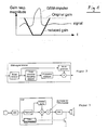
- FIG. 1 is schematically a glitch, such as a GSM pulse shown.
- a glitch such as a GSM pulse shown.
- the lowering of the original signal, as in FIG. 1 represented, not abruptly, but gently and likewise the increase of the reinforcement takes place again gently.
- the gap between the original signal in the millisecond range which is the result of dynamic signal suppression, can not be recognized by the human brain, or the human brain effectively fills in the signal gap so that no interruption of the original signal is perceptible.
- FIG. 2 is shown on the basis of a simplified block diagram, a GSM signal detector.
- a signal is detected, wherein it is first determined whether it is, for example, a GSM signal. If there is a known interference signal, another pulse is detected at the next expected time, and if in fact another pulse occurs at this time, the probability of assuming that there are corresponding interfering pulses actually increases. Now, the suppression of the glitches can be triggered, as previously with reference to FIG. 1 described.
- the interference pulses such as GSM glitches
- the interference pulses have a characteristic spectrum after demodulation by parasitic non-linearities.
- the amplification in those frequency bands which are particularly affected by the interference signal are lowered dynamically and smoothly by a few dB in comparison with the bands of less interest, in order to be correspondingly raised to the original amplification after the impulse.
- the presented method or the measures according to the invention can also be used analogously for other interference pulses.
- a prerequisite is, of course, that the glitches occur with known constant repetition frequency and also preferably the duty-cyle is known.
- the method presented according to the invention is also applicable to other mobile telephone standards, such as the CDMA standard customary in North America, which produces a different kind of interference. That is, with the aid of a suitable detector, the presence of characteristic noise or interference signals is detected and then filtered out of the audio signal in terms of time and spectrally with a suitable filter.
- the knowledge of the repetition frequency can also be determined only during the operation of the hearing device, ie it is detected on the basis of a signal analysis that a specific pulse repetition pattern does not belong to a desired signal but to an interfering signal and should accordingly be removed in this way. so that the disturbance is no longer perceptible.
- the filtering out of glitches can be done in hearing aids, as shown schematically in FIG. 3 shown, both in the digital signal processing area using digital filters, as well as by means of analog filters, which For example, in the area between the digital signal processing (DSP) and the digital / analog converter (DAC) and the speaker are arranged.
- FIG. 3 shows a simplified block diagram of a hearing aid with a GSM signal detector, which acts either on the gain in the DSP or alternatively directly to the analog output signal (where ADC stands for analog / digital converter, analog / digital converter).
- the disturbances in both the microphone path as well as e.g. can be fed in an analog or digital, wired or wireless transmission link between two hearing aids or a hearing aid and another device in the hearing aid system, and the measures described are applicable regardless of the feed point.
- the proposed invention represents a preferred solution for increasing the noise immunity of hearing aids. It is of course possible that the measures proposed according to the invention alone are not sufficient, but it is for example possible in conjunction with other typical measures, such as ferrite beads, RC- Filter, etc. to achieve additional interference suppression.
Landscapes
- Engineering & Computer Science (AREA)
- Signal Processing (AREA)
- Health & Medical Sciences (AREA)
- General Health & Medical Sciences (AREA)
- Neurosurgery (AREA)
- Otolaryngology (AREA)
- Physics & Mathematics (AREA)
- Acoustics & Sound (AREA)
- Computer Networks & Wireless Communication (AREA)
- Noise Elimination (AREA)
- Filters And Equalizers (AREA)
- Networks Using Active Elements (AREA)
Claims (12)
- Procédé pour affaiblir les signaux parasites qui apparaissent avec une fréquence de répétition dont on sait globalement qu'elle est constante, quand on utilise des prothèses auditives, selon lequel dans la partie numérique du traitement de signal d'une prothèse auditive, on détecte sur la base d'un signal dérivé au moins de la voie de signal audio la fréquence de répétition du signal parasite, et en cas de détection d'une fréquence de répétition dont on sait qu'elle est constante le signal audio est au moins en partie affaibli ou atténué au moins au moment attendu de la prochaine répétition du signal parasite,
caractérisé en ce que cela est obtenu grâce à une réduction de l'amplitude de signal audio, à l'aide d'une variation du facteur d'amplification d'un élément amplificateur qui agit par multiplication sur l'amplitude de signal audio, le facteur d'amplification étant réduit progressivement avant le moment attendu de la prochaine répétition du signal parasite à l'intérieur de 0,5-10 ms et étant augmenté progressivement après l'impulsion parasite à l'intérieur de 0,5-10 ms pour atteindre à nouveau l'amplification d'origine. - Procédé selon la revendication 1, caractérisé en ce que la détection se fait sur le cycle de fonctionnement et/ou sur la fréquence de base du signal parasite.
- Procédé selon l'une des revendications 1 et 2, caractérisé en ce que la décision pour savoir si un modèle de signal qui se répète régulièrement constitue un signal parasite est prise pendant le fonctionnement de la prothèse auditive.
- Procédé selon l'une des revendications 1 à 3, caractérisé en ce qu'un paquet d'impulsions d'une période et d'un cycle de fonctionnement correspondants est tout d'abord détecté, et après une autre période attendue, le signal est affaibli d'une certaine quantité au moment de l'impulsion attendue et, au cas où au moment attendu une autre impulsion est effectivement détectée, le signal est encore plus affaibli lors de l'impulsion attendue suivante.
- Procédé selon l'une des revendications 1 à 4, caractérisé en ce que si aucune impulsion n'est détectée, l'affaiblissement dynamique de signal est réduit à 0.
- Procédé selon l'une des revendications 1 à 5, caractérisé en ce que l'affaiblissement de signal se fait dans la zone numérique du traitement de signal d'une prothèse auditive.
- Procédé selon l'une des revendications 1 à 6, caractérisé en ce que l'affaiblissement de signal se fait de manière analogique, par exemple dans la zone entre un convertisseur numérique/analogique et le haut-parleur.
- Procédé selon l'une des revendications 1 à 7, caractérisé en ce que l'affaiblissement de signal est très court, comme par exemple de l'ordre de la milliseconde.
- Dispositif pour affaiblir des signaux parasites sur une prothèse auditive, caractérisé par un détecteur pour la détection des signaux parasites avec une fréquence de répétition dont on sait globalement qu'elle est constante, et par un affaiblissement de signal dynamique dont l'action est couplée avec le détecteur, le détecteur étant disposé dans la zone du traitement de signal numérique de la prothèse auditive et étant relié, pour la détection de signaux auditifs avec une fréquence dont on sait globalement qu'elle est constante, au moins à la voie de signal audio, et l'affaiblissement de signal dynamique étant obtenu grâce à une réduction de l'amplitude de signal audio, à l'aide d'un élément amplificateur avec lequel le signal audio est multiplié par un facteur d'amplification variable dans le temps.
- Dispositif selon la revendication 9, caractérisé en ce que l'affaiblissement de signal dynamique est prévu dans la zone du traitement de signal numérique de la prothèse auditive.
- Dispositif selon la revendication 9, caractérisé en ce que l'affaiblissement de signal dynamique est prévu dans la zone située avant le haut-parleur de la prothèse auditive.
- Utilisation du procédé selon l'une des revendications 1 à 8 pour affaiblir des signaux parasites tels qu'ils apparaissent lors de l'émission de signaux d'émission selon les normes de téléphonie mobile, en particulier GSM ou CDMA.
Priority Applications (3)
| Application Number | Priority Date | Filing Date | Title |
|---|---|---|---|
| DE200450010063 DE502004010063D1 (de) | 2004-11-12 | 2004-11-12 | Störsignalfilter in Hörgeräten |
| DK04026906T DK1501200T3 (da) | 2004-11-12 | 2004-11-12 | Støjfilter i et høreapparat |
| EP20040026906 EP1501200B1 (fr) | 2004-11-12 | 2004-11-12 | Filtre de bruit dans une prothèse auditive |
Applications Claiming Priority (1)
| Application Number | Priority Date | Filing Date | Title |
|---|---|---|---|
| EP20040026906 EP1501200B1 (fr) | 2004-11-12 | 2004-11-12 | Filtre de bruit dans une prothèse auditive |
Publications (3)
| Publication Number | Publication Date |
|---|---|
| EP1501200A2 EP1501200A2 (fr) | 2005-01-26 |
| EP1501200A3 EP1501200A3 (fr) | 2005-03-16 |
| EP1501200B1 true EP1501200B1 (fr) | 2009-09-16 |
Family
ID=33484110
Family Applications (1)
| Application Number | Title | Priority Date | Filing Date |
|---|---|---|---|
| EP20040026906 Active EP1501200B1 (fr) | 2004-11-12 | 2004-11-12 | Filtre de bruit dans une prothèse auditive |
Country Status (3)
| Country | Link |
|---|---|
| EP (1) | EP1501200B1 (fr) |
| DE (1) | DE502004010063D1 (fr) |
| DK (1) | DK1501200T3 (fr) |
Families Citing this family (5)
| Publication number | Priority date | Publication date | Assignee | Title |
|---|---|---|---|---|
| US7688991B2 (en) | 2006-05-24 | 2010-03-30 | Phonak Ag | Hearing assistance system and method of operating the same |
| EP1860914B1 (fr) * | 2006-05-24 | 2008-12-03 | Phonak AG | Système pour l'assistance auditive et procédé correspondant |
| ATE509478T1 (de) | 2006-12-20 | 2011-05-15 | Phonak Ag | Hörhilfesystem und betriebsverfahren dafür |
| US20110300874A1 (en) * | 2010-06-04 | 2011-12-08 | Apple Inc. | System and method for removing tdma audio noise |
| US8837749B2 (en) | 2011-03-09 | 2014-09-16 | Apple Inc. | Managing the effect of TDMA noise on audio circuits |
Family Cites Families (5)
| Publication number | Priority date | Publication date | Assignee | Title |
|---|---|---|---|---|
| SE9603982L (sv) * | 1996-10-31 | 1998-05-01 | Transistor Ab | Anordning för att undertrycka harmoniska störningar vid signalöverföring |
| US6137888A (en) * | 1997-06-02 | 2000-10-24 | Nortel Networks Corporation | EM interference canceller in an audio amplifier |
| US6307944B1 (en) * | 1998-03-02 | 2001-10-23 | Knowles Electtronics Llc | System for mitigating RF interference in a hearing aid |
| EP1104645B1 (fr) * | 1998-08-13 | 2003-02-05 | Siemens Audiologische Technik GmbH | Prothese auditive pourvue d'un dispositif permettant de supprimer les signaux parasites electromagnetiques, et procede permettant de supprimer lesdits signaux dans les protheses auditives |
| DE10052906A1 (de) * | 2000-10-25 | 2002-05-08 | Siemens Ag | Tragbares elektronisches Gerät |
-
2004
- 2004-11-12 EP EP20040026906 patent/EP1501200B1/fr active Active
- 2004-11-12 DE DE200450010063 patent/DE502004010063D1/de active Active
- 2004-11-12 DK DK04026906T patent/DK1501200T3/da active
Also Published As
| Publication number | Publication date |
|---|---|
| EP1501200A2 (fr) | 2005-01-26 |
| DK1501200T3 (da) | 2010-01-18 |
| DE502004010063D1 (de) | 2009-10-29 |
| EP1501200A3 (fr) | 2005-03-16 |
Similar Documents
| Publication | Publication Date | Title |
|---|---|---|
| DE69628411T2 (de) | Vorrichtung und Verfahren zur Geräuschreduzierung eines Sprachsignals | |
| EP1456839B1 (fr) | Procede et dispositif de suppression de signaux perturbateurs periodiques | |
| DE19854201A1 (de) | Hörhilfegerät mit Induktionsspule sowie Verfahren zur Reduzierung magnetischer Störfelder | |
| EP3121962B1 (fr) | Compensation d'attenuation de signal lors de la transmission de signaux d'emission d'un appareil radio mobile | |
| DE69733000T2 (de) | Verfahren und schaltung zur reduktion von offsetspannung eines signals | |
| DE10232615A1 (de) | Verfahren zum Reduzieren von Mehrwegrauschen, Vorrichtung zum Reduzieren von Mehrwegrauschen und FM-Empfänger | |
| DE60036981T2 (de) | Empfänger und Verfahren zur Regelung der Verstärkung desselben | |
| EP1104645B1 (fr) | Prothese auditive pourvue d'un dispositif permettant de supprimer les signaux parasites electromagnetiques, et procede permettant de supprimer lesdits signaux dans les protheses auditives | |
| DE19782102B4 (de) | Schaltung zum Eliminieren äußerer Interferenzsignale in einem Mobiltelefon mit Vielfachzugriff durch Codetrennung | |
| EP1501200B1 (fr) | Filtre de bruit dans une prothèse auditive | |
| DE60110588T2 (de) | Drahtloser sende-empfänger mit subtraktivem filter zur kompensation von gesendeten und empfangenen artefakten | |
| EP1542500A2 (fr) | Prothèse acoustique avec suppression de bruit et procédé correspondant pour la suppression du bruit | |
| EP1458216B1 (fr) | Appareil et procédé à l'adaption de microphones dans une prothèse auditive | |
| EP1282943B1 (fr) | Procede et dispositif pour eviter un etat perturbateur | |
| EP1961126B1 (fr) | Procede pour le fonctionnement d'un appareil de communication | |
| EP1351550A1 (fr) | Procédé d'adaptation d'une amplification de signal dans une prothèse auditive et prothèse auditive | |
| DE60206538T2 (de) | Empfänger für ein mobiles Funkkommunikationsendgerät | |
| DE3111825A1 (de) | Empfaengervorrichtung | |
| DE10148584B4 (de) | Empfänger und Verfahren zur Unterdrückung von kurzzeitigen Störpulsen mit Bursts | |
| EP1794838A1 (fr) | Amplificateur d'antenne de vehicule comportant des moyens de protection contre les decharges electrostatiques dans l'entree | |
| DE3017781C2 (fr) | ||
| DE19953731A1 (de) | Verfahren zur Auswahl einer von mehreren Antennen einer Antennendiversity-Empfangsanlage sowie Antennendiversity-Empfangsanlage | |
| EP2677663B1 (fr) | Squelch de niveau avec une immunité élevée contre les interférences d'impulsions | |
| DE60312956T2 (de) | Antennenverstärker und geteilt aufgebauter Antennenverstärker | |
| DE10201526A1 (de) | Autoradiosystem |
Legal Events
| Date | Code | Title | Description |
|---|---|---|---|
| PUAI | Public reference made under article 153(3) epc to a published international application that has entered the european phase |
Free format text: ORIGINAL CODE: 0009012 |
|
| AK | Designated contracting states |
Kind code of ref document: A2 Designated state(s): AT BE BG CH CY CZ DE DK EE ES FI FR GB GR HU IE IS IT LI LU MC NL PL PT RO SE SI SK TR |
|
| AX | Request for extension of the european patent |
Extension state: AL HR LT LV MK YU |
|
| PUAL | Search report despatched |
Free format text: ORIGINAL CODE: 0009013 |
|
| AK | Designated contracting states |
Kind code of ref document: A3 Designated state(s): AT BE BG CH CY CZ DE DK EE ES FI FR GB GR HU IE IS IT LI LU MC NL PL PT RO SE SI SK TR |
|
| AX | Request for extension of the european patent |
Extension state: AL HR LT LV MK YU |
|
| RIC1 | Information provided on ipc code assigned before grant |
Ipc: 7H 04R 25/00 B Ipc: 7H 04B 1/10 A |
|
| 17P | Request for examination filed |
Effective date: 20050721 |
|
| AKX | Designation fees paid |
Designated state(s): CH DE DK LI |
|
| 17Q | First examination report despatched |
Effective date: 20051017 |
|
| GRAP | Despatch of communication of intention to grant a patent |
Free format text: ORIGINAL CODE: EPIDOSNIGR1 |
|
| GRAS | Grant fee paid |
Free format text: ORIGINAL CODE: EPIDOSNIGR3 |
|
| GRAA | (expected) grant |
Free format text: ORIGINAL CODE: 0009210 |
|
| AK | Designated contracting states |
Kind code of ref document: B1 Designated state(s): CH DE DK LI |
|
| REG | Reference to a national code |
Ref country code: CH Ref legal event code: EP |
|
| REF | Corresponds to: |
Ref document number: 502004010063 Country of ref document: DE Date of ref document: 20091029 Kind code of ref document: P |
|
| REG | Reference to a national code |
Ref country code: CH Ref legal event code: NV Representative=s name: TROESCH SCHEIDEGGER WERNER AG |
|
| REG | Reference to a national code |
Ref country code: DK Ref legal event code: T3 |
|
| PLBE | No opposition filed within time limit |
Free format text: ORIGINAL CODE: 0009261 |
|
| STAA | Information on the status of an ep patent application or granted ep patent |
Free format text: STATUS: NO OPPOSITION FILED WITHIN TIME LIMIT |
|
| 26N | No opposition filed |
Effective date: 20100617 |
|
| PGFP | Annual fee paid to national office [announced via postgrant information from national office to epo] |
Ref country code: DK Payment date: 20151125 Year of fee payment: 12 Ref country code: CH Payment date: 20151127 Year of fee payment: 12 |
|
| REG | Reference to a national code |
Ref country code: DK Ref legal event code: EBP Effective date: 20161130 |
|
| REG | Reference to a national code |
Ref country code: CH Ref legal event code: PL |
|
| PG25 | Lapsed in a contracting state [announced via postgrant information from national office to epo] |
Ref country code: CH Free format text: LAPSE BECAUSE OF NON-PAYMENT OF DUE FEES Effective date: 20161130 Ref country code: LI Free format text: LAPSE BECAUSE OF NON-PAYMENT OF DUE FEES Effective date: 20161130 |
|
| PG25 | Lapsed in a contracting state [announced via postgrant information from national office to epo] |
Ref country code: DK Free format text: LAPSE BECAUSE OF NON-PAYMENT OF DUE FEES Effective date: 20161130 |
|
| REG | Reference to a national code |
Ref country code: DE Ref legal event code: R084 Ref document number: 502004010063 Country of ref document: DE |
|
| P01 | Opt-out of the competence of the unified patent court (upc) registered |
Effective date: 20230530 |
|
| PGFP | Annual fee paid to national office [announced via postgrant information from national office to epo] |
Ref country code: DE Payment date: 20231129 Year of fee payment: 20 |