EP1501006A2 - Apparatus, method and computer program for controlling a pointing device - Google Patents
Apparatus, method and computer program for controlling a pointing device Download PDFInfo
- Publication number
- EP1501006A2 EP1501006A2 EP04014096A EP04014096A EP1501006A2 EP 1501006 A2 EP1501006 A2 EP 1501006A2 EP 04014096 A EP04014096 A EP 04014096A EP 04014096 A EP04014096 A EP 04014096A EP 1501006 A2 EP1501006 A2 EP 1501006A2
- Authority
- EP
- European Patent Office
- Prior art keywords
- pointing device
- adjustment
- actual operation
- control apparatus
- region
- Prior art date
- Legal status (The legal status is an assumption and is not a legal conclusion. Google has not performed a legal analysis and makes no representation as to the accuracy of the status listed.)
- Withdrawn
Links
Images


Classifications
-
- G—PHYSICS
- G06—COMPUTING OR CALCULATING; COUNTING
- G06F—ELECTRIC DIGITAL DATA PROCESSING
- G06F3/00—Input arrangements for transferring data to be processed into a form capable of being handled by the computer; Output arrangements for transferring data from processing unit to output unit, e.g. interface arrangements
- G06F3/01—Input arrangements or combined input and output arrangements for interaction between user and computer
- G06F3/03—Arrangements for converting the position or the displacement of a member into a coded form
- G06F3/033—Pointing devices displaced or positioned by the user, e.g. mice, trackballs, pens or joysticks; Accessories therefor
- G06F3/038—Control and interface arrangements therefor, e.g. drivers or device-embedded control circuitry
Definitions
- the present invention relates to a technical field of a pointing device for entering an operation of a user to an electronic instrument.
- a pointing device has been used for a cellular phone, a PDA (personal digital assistance), a notebook personal computer (hereinafter, referred to as a notebook PC), a game machine or the like.
- the pointing device has a function to move a display position of an object to be controlled (a pointer, a cursor or the like) on a display screen in response to operating force to an arbitrary direction by a user (hereinafter, also referred to as "an operator” in some cases).
- an analog pointing device such as a mouse, a track ball and a joystick has been widely used.
- Fig. 7 is a view showing a relationship between the operating direction and the amount of operation in a conventional pointing device.
- this drawing shows a relationship between an operating direction and an amount of operation in a joystick type pointing device as an object, which designates a reference point O as a center and performs the control based on an operating direction and an amount of operation from the reference point O.
- the reference point in the system of coordinates is defined as (0, 0) and the operating position in the system of coordinates as A(x, y).
- each of x and y takes on any value of a positive value, a negative value and zero.
- the operating direction ⁇ is determined by a ratio of the x and the y and by a combination of the x and the y, each of which takes on any value of a positive value, a negative value and zero. Note that the case where both of the x and the y are zero is excluded.
- Figs. 8A to 8G are explanatory views showing the relationships between the amounts of operation and operating speeds in the conventional pointing devices.
- a casing thereof is compact. Accordingly, on such a portable electronic instrument, a device made in consideration of a size and motion of a hand of the user, that is what-is-called a full-scaled keyboard is difficult to mount. Therefore, in the portable electronic instrument, the pointing device plays an important role as a man-machine interface between the user and the electronic instrument. However, under such circumstances, in the actual portable electronic instrument, it is difficult to ensure a sufficient area for mounting the pointing device due to limitations of a size of the casing.
- the portable electronic instrument under such circumstances has a problem that the portable electronic instrument cannot give a sufficiently comfortable operation feeling to the user.
- Patent Document 1 Japanese Patent Laid-Open No. H5 (1993)-265649 (hereinafter, referred to as Patent Document 1), a pointing device which adjusts such a shift is disclosed.
- Patent Document 1 First, an ARCTAN value of the pointing device is calculated by means of outputs of two sensors. Then, in Patent Document 1, actual outputs of the sensors are adjusted to approximate values thereto so that the ARCTAN value can be 0, 45, 90, 135, 180, 225 and 270. In such a way, in Patent Document 1, a configuration is formed in which data can be obtained as a displacement in a specific direction even if the pointing device is roughly operated.
- Patent Document 2 Japanese Patent Laid-Open No. H10 (1998)-154038 (hereinafter, referred to as Patent Document 2), disclosed is a pointing input device which stores a shift from a reference direction as personal data and adjusts a shift caused the habit inherent in the operator.
- the present invention is a control apparatus for controlling a position of an object to be controlled, the object being to be displayed on a display (208A) in response to an operation of a pointing device (11) by a user, comprising:
- the pointing device control apparatus having the above-described configuration further comprises selectionmeans (32) capable of choosing an adjustment region, which the user wishes to employ for adjusting the actual operation direction, out of previously prepared plural types of the adjustment regions.
- the pointing device control apparatus further comprises synthesis means (34) for synthesizing at least two types of the adjustment regions, the regions being selected by the user out of the previously prepared plural types of adjustment regions, as the adjustment region, the region being to be employed for adjusting the actual operation direction.
- the adjustment control means (S704 and S705) adjusts the information indicating the actual operation direction in order to adjust the actual operation direction to the predetermined direction when any of an amount of operation of the pointing device and an operating speed thereof is larger than a predetermined threshold value (Th).
- a plurality of the adjustment regions are set with a center position (0) of the movable range of the pointing device designated as a reference.
- the plurality.of adjustment regions are made of at least two types of the adjustment regions (73 and 74) different in size from each other.
- the movable range includes an area where any adjustment region is not set, the included region being set with the center position taken as the reference.
- the at least two types of adjustment regions can also be configured to be different from each other in a longitudinal direction and in a lateral direction in the movable range of the pointing device.
- an electronic instrument a cellular phone, a PDA or the like
- a pointing device control apparatus having each configuration described above.
- the foregoing object is achieved also by a software program realizing the pointing device control apparatus having each configuration described above and the pointing device control method by a computer, and a computer-readable recording medium storing the software program therein.
- Fig. 1 is a block diagram illustrating a configuration of a cellular phone 1 to which the present invention is applicable.
- the cellular phone 1 includes a pointing device 11, an antenna 201, a wireless transceiver unit 202, a control unit 203, an operation unit 207, a display unit 208, a microphone 209, and a speaker 210.
- the control unit 203 includes a CPU (Central Processing Unit) 200, an operating memory 204, a holding memory 205, an ID memory 206, and unillustrated hardware.
- the CPU 200 executes a group of programs prestored in the operating memory 204, and thus manages the respective units of the cellular phone 1.
- the CPU 200 of the control unit 203 detects a call number of the cellular phone 1 of its own from signals demodulated in the wireless transceiver unit 202, and thus issues a notice of an incoming call. Furthermore, the CPU 200 of the control unit 203 processes voice signals and digital data signals, and thus realizes a voice call utilizing the microphone 209 and the speaker 210 and data communications made as transmission/receipt of email and a connection to a server.
- the CPU 200 of the control unit 203 complies with an instruction entered by a user through the operation unit 207 and the pointing device 11.
- the pointing device 11 is a unit operated by the user for the purpose of changing a position (values of the abscissae and the ordinates in the system of coordinates) of an object to be operated, such as a pointer and a cursor, which is displayed on a display 208A of the display unit 208 (hereinafter, the object to be operated will be referred to as a "pointer"). Then, the pointing device 11 outputs a signal indicating value (x, y) of the abscissae and the ordinates in a two-dimensional coordinate system in response to the operation of the user. This values (x, y) in the coordinate system corresponds to a predetermined coordinate system employed in the control unit 203.
- an actual aspect of the pointing device 11 is, for example, an input device (auxiliary input device) such as a joystick and a pointing stick.
- auxiliary input device such as a joystick and a pointing stick.
- the trackpad is also applicable as the pointing device 11 according to this embodiment.
- the pointing device 11 is not limited to these conventional input devices.
- devices operable by the user for the purpose of changing the position (values of the abscissae and the ordinates in the coordinate system) of the pointer (cursor) displayed on the display 208A are widely applicable.
- control unit 203 detects the operation performed for the pointing device 11 by the user based on the signal indicating the above-described values (x, y) of the abscissae and the ordinates in the coordinate system.
- control unit 203 controls the position of the pointer to be displayed on the display 208A on the display unit 208 in response to the detected operation (an operating direction and an amount of operation).
- the operation unit 207 includes a keyboarding unit (not shown) through which the user enters information.
- the operation unit 207 is used for entering a telephone number when the user makes a phone call, for entering text in such a case of registering an address in an address book, and for entering settings for a variety of functions.
- the display unit 208 includes the display 208A such as a liquid crystal display device.
- the display unit 208 displays on the display 208A a variety of entered contents linked to the operation of the user for the operation unit 207.
- the display unit 208 displays on the display 208A the pointer linked to the operation of the user for the pointing device 11.
- the ID memory 206 holds the call number (originated number) of the cellular phone 1 of its own.
- the CPU 200 uses the call number (originated number) retrieved from the ID memory 206 and collates data corresponding to a predetermined position of the demodulated signals with the call number.
- the operating memory (RAM: random access memory) 204 is used as a work area for the operation of the CPU 200.
- the holding memory 205 is a non-volatile memory (a flash memory or the like), and holds, for example, an operation program for the CPU 200, a variety of parameters, user data (for example, an email document and the telephone number), and the like.
- a part of the operating memory 204, a part of the holding memory 205 and a part of the ID memory 206 are physically realized in divided regions of the same device.
- the antenna 201 transmits/receives a phase-modulated electric wave, and in addition, has similar functions to those of an antenna of a publicly known wireless communications terminal device.
- the wireless transceiver unit 202 demodulates the electric wave received from the antenna 201, and performs phase modulation for the digital signals outputted from the control unit 203. Moreover, the wireless transceiver unit 202 has similar functions to those of a wireless transceiver unit of a publicly known wireless communications terminal device.
- the microphone 209 receives a voice of the user.
- the speaker 210 outputs a voice (a sound) to the user.
- Fig. 2 is a block diagram schematically showing the configuration of control of the pointing device 11, which is executed by the CPU 200 in the cellular phone 1 according to this embodiment.
- the CPU 200 of the control unit 203 does such broadly-categorized things as executes and controls the sensing module 13, the adjustment module 30, and a pointer display control module 36.
- the CPU 200 refers to parameters stored in a parameter storage area 21 in the holding memory 205.
- the modules are predetermined functional units realized by software programs and the hardware.
- the sensing module 13 has a function to detect the operation by the user of the pointing device 11 based on the signal indicating the values (x, y) of the abscissae and the originates in the coordinate system outputted from the pointing device 11 (details will be described later).
- the adjustment module 30 has a function to implement adequate adjustment processing in order to improve operability for the user in the case of determining a display position of the pointer based on output data of the sensing module 13 (details will be described later).
- the pointer display control module 36 has a function to control the position of the pointer displayed on the display 208A of the display unit 208 in accordance with output data (a control signal) of the adjustment module 30.
- the sensing module 13 has an operating direction sensing program 13a, an amount of operation sensing program 13b, an operating speed sensing program 13c, and an operating acceleration sensing program 13d.
- the group of these programs is retrieved from the holding memory 205 to the CPU 200 or the operating memory 204.
- the operating direction sensing program 13a has a function to sense the operating direction of the pointing device 11 based on the signal outputted from the pointing device 11.
- the amount of operation sensing program 13b has a function to sense the amount of operation of the pointing device 11 based on the signal outputted from the pointing device 11.
- the operating speed sensing program 13c has a function to sense the operating speed of the pointing device 11 based on the signal outputted from the pointing device 11. Note,that the operating speed may be calculated by differentiating the amount of operation sensed by utilizing the amount of operation sensing program 13b.
- the operating acceleration sensing program 13d has a function to sense the operating acceleration of the pointing device 11 based on the signal outputted from the pointing device 11. Note that the operating acceleration may be calculated by differentiating the operating speed detected by utilizing the operating speed sensing program 13c.
- the holding memory 205 stores an adjustment region (an adjustment target region) set up by an adjustment function setting program 33 to be described later.
- the adjustment region set up by this program is effective until another adjustment region is newly set up based on the parameters prestored in the parameter storage area 21.
- Fig. 3 is a view schematically showing a relationship between the operating directions of the pointing device 11 and an adjustment direction thereof, in which an adjustment is performed by the adjustment module. 30 executed by the control unit 203 in this embodiment.
- the parameters for setting the adjustment target region (adjustment region 70) by the adjustment module 30 and the adjustment direction corresponding to the adjustment region are prestored.
- Such adjustment processing is executed in the case where there are actual operation directions (operating directions 50 and 50') detected by the operating direction sensing program 13a in the region to be processed (adjustment region) 70 set up based on the parameters retrieved from the parameter storage area 21.
- the' operating directions 50 and 50' based on actual operations by the user are adjusted to an adjustment direction 60 indicating an operating direction after the adjustment by the adjustment processing using the adjustment module 30.
- the amount of operation (a magnitude of a vector) is not changed.
- the parameters for setting up the adjustment region 70 and the corresponding adjustment direction 60 are stored, which are:
- the parameters stored in the parameter storage area 21 are not limited to these.
- the respective parameters to be stored may be ones prestored in the parameter storage area 21, or may be ones previously entered by the user by utilizing the operation unit 207.
- the adjustment module 30 includes a parameter setting program 31, a parameter selection program 32, an adjustment function setting program 33, a switching/synthesis program 34, and an adjustment control program 35.
- the parameter setting program 31 has a function to set up (develop) the parameters retrieved fromthe parameter storage area 21 into the operating memory 204 and the like.
- the parameter selection program 32 has a function to choose any parameter desired by the user out of the plural types of parameters prestored in the above-described parameter storage area 21.
- the parameter selection program 32 displays multiple sets consisting of the plural types of parameters as alternatives on the display 208A.
- Such sets consisting of the plural types of parameters corresponds, for example, to a pattern of the plural types of adjustment regions among a plurality of the patterns illustrated in Figs. 4A to 4E to be described later.
- the user chooses a desired multiple sets consisting of the plural types of the parameters by utilizing the operation unit 207.
- the user can change levels of comfortableness felt while operating the pointing device 11 according to his/her preference.
- the adjustment function setting program 33 has functions to set up the adjustment region 70 based on the parameters chosen by the parameter selection program 32 and to set the adjustment direction 60 based on the set adjustment region.
- the switching/synthesis program 34 has a function to choose an adjustment region out of the plurality of adjustment regions prestored in the holding memory 205. Then, the switching/synthesis program 34 has functions to change an adjustment region (first adjustment region) used currently by the adjustment module 30 based on the chosen adjustment region (second adjustment region) or, otherwise, to synthesize the first and second adjustment regions, and so on.
- the adjustment control program 35 has a function to adjust the operating directions 50 and 50' based on the actual operations by the user to the adjustment direction 60 in the adjustment region 70 set at present.
- the adjustment region setting program 33 sets up the sector-shaped adjustment region 70 as shown in Fig. 3, in which the angle at the center of the adjustment region is measure ⁇ in radians and the adjustment region radius is R.
- the adjustment function setting program 33 sets up the adjustment direction 60 indicated by a solid-line arrow in a range of the set adjustment region 70.
- a specific setting direction of the adjustment region 60 is set, for example, at a half of the angle at the center of measure ⁇ in radians.
- the switching/synthesis program 34 has:
- Figs. 4A to 4E are views illustrating the adjustment regions settable by the adjustment module 30, in which the adjustments are executed by the CPU 200 in the cellular phone 1 according to this embodiment.
- each of Figs. 4A to 4E distinguishes among the adjacent adjustment regions by hatching using oblique lines for the purpose of clarifying the individual adjustment regions.
- FIG. 4A four adjustment regions 71 in which the angle at the center of measure ⁇ is equal to ⁇ /2 (at angle of 90 degrees) are shown.
- Fig. 4B eight adjustment regions 72 in which the angle at the center of measure ⁇ in radians is equal to n/4 (at angle of 45 degrees) are shown.
- each operation circle 80 having the reference point O as a central point is one in which a physically operable range of the pointing device 11 is represented as a circle having a radius of maximum amount of operation Rmax.
- the switching/synthesis program 34 can change the adjustment regions 71 forming the pattern shown in Fig. 4A to the adjustment regions 72 forming the pattern shown in Fig. 4B.
- the switching/synthesis program 34 can set up a plurality of adjustment regions forming a pattern shown in Fig. 4E by synthesizing the adjustment regions 71 forming the pattern shown in Fig. 4A and the adjustment regions 72 forming the pattern shown in Fig. 4B.
- the switching/synthesis program 34 can set up adjustment regions 75 forming a pattern as shown in Fig. 4D by synthesizing the adjustment regions 72 forming the pattern shown in Fig. 4B and an unadjusted region (corresponding to a grid-shaped portion inside an operation circle with the radius r).
- the adjustment control program 35 determines whether or not an operation state of the pointing device 11 (the operating directions 50 and 50') detected by the sensing module 13 is of the operation in the adjustment region 70 currently set up by the adjustment function setting program 33. Next, when it is determined that such an operation state is within the adjustment region, the adjustment control program 35 outputs a control signal indicating the adjustment direction 60 preset so as to correspond to the adjustment region, as the current operation state of the pointing device 11, to the pointer display control module 36.
- the adjustment region 70 shown.in Fig. 3 is set up in the following manner.
- the CPU 200 executes the parameter selection program 32, and thus, the angle at the center of the adjustment region expressed by measure ⁇ in radians and the radius R of the adjustment region, which are stored in the parameter storage area 21, are chosen as the set of the desired parameters chosen by the user.
- the CPU 200 executes the adjustment function setting program 33, and thus, based on the selected angle at the center of the adjustment region expressed by measure ⁇ in radians and adjustment radius R, the adjustment region 70 shaped like a sector subtended by the angle at the center of measure ⁇ in radians and the radius of R with the reference point O taken as a center is set up.
- the CPU 200 executes the respective programs (13a to 13d) of the above-described sensing module 13, and thus the operation state of the pointing device 11 by the user is sensed.
- the sensing module 13 transfers to the adjustment control program 35 signals (information), as the operation state of the pointing device 11, concerning the operating direction (actual operation direction), the amount of operation, the operating speed and the operating acceleration.
- the adjustment control program 35 determines whether or not the operation of the pointing device 11 is the operation in the adjustment region 70 preset by the adjustment function setting program 33. Then, when it is determined that the operation of the pointing device 11 is the operation within the adjustment region concerned, the adjustment control program 35 outputs the control signal indicating the adjustment direction 60 so preset as to correspond to the adjustment region, as the present operation state of the pointing device 11, to the pointer display control module 36. Meanwhile, when it is determined in the determination described above that the operation is an operation outside the adjustment region, the adjustment control program 35 outputs a control signal in response to the actual operation of the pointing device 11 to the pointer display control module 36 without making any adjustment.
- the adjustment control program 35 performs processing of converting the directions of the amount of operation vectors ⁇ and ⁇ ' oriented toward the operating directions 50 and 50' to an orientation designated by the adjustment direction 60 without changing the magnitudes of the vectors. Then, this direction conversion processing can be realized by adjusting (replacing) the information indicating the operating directions 50 and 50' to information indicating the adjustment direction 60.
- the information indicating the adjustment direction 60 is one acquired from the parameters prestored in the parameter storage area 21.
- the operation of the pointing device 11, which is adjusted to the adjustment direction 60, is displayed on the display unit 208 as a pointer moving toward the adjustment direction 60 by a distance corresponding to the amount of operation ⁇ .
- the respective adjustment regions shown in Figs. 4A to 4E are set up with the angle at the center of measure ⁇ in radians and the radius of the adjustment region R used as the parameters.
- the circle 80 shown in Fig. 4A is quartered by the adjustment regions 71 in which the angle at the center of measure ⁇ in radians is equal to measure ⁇ /2 (at angle of 90 degrees) in radians and the radius R is equal to Rmax.
- each adjustment direction 61 is set up in a direction bisecting the angle at the center of measure ⁇ in radians.
- the operating directions of the pointing device 11, which correspond to the ranges of the adjustment regions 71 are adjusted to four directions shown by the adjustment directions 61 orthogonal to each other.
- the operating direction of the pointing device 11 in an adjustment region 71a is adjusted to an adjustment direction 61a.
- the operating direction of the pointing device 11 in an adjustment region 71b is adjusted to an adjustment direction 61b.
- the operation circle 80 shown in Fig. 4B is divided into eight equal parts by the adjustment regions 72 in which the angle at the center of measure ⁇ in radians is equal to measure n/4 (at angle of 45 degrees) in radians and the radius R is equal to Rmax.
- each adjustment direction 71 is set up in a direction bisecting the angle at the center of measure ⁇ in radians of each adjustment region 72.
- the adjustment regions based on the operation circle in which the radius R is equal to Rmax may be set up in accordance with the number n of dividing the operation circle 80, without using the angle at the center of measure ⁇ in radians as the parameter.
- the operation circle 80 shown in Fig. 4C is divided into two types of adjustment regions 73 and 74 in which the radius R is equal to Rmax and the angles at the centers are measures ⁇ and ⁇ ' in radians.
- the adjustment module 30 of this embodiment it is also possible for the adjustment module 30 of this embodiment to set up adjustment regions forming a pattern other than those having the equally divided adjustment regions illustrated in Figs. 4A and 4B.
- the adjustment regions 75 forming a pattern shown in the operation circle 80 shown in Fig. 4D is obtained by synthesizing the adjustment regions 72 shown in Fig. 4B and an unadjusted range circle 81 with the radius r.
- the unadjusted range circle 81 represents a region to which the adjustment of the operating direction is not performed.
- the parameter selection program 32 chooses the radius r of the unadjusted range circle 81 from the parameter storage area 21. Then, the adjustment regions 75 in the pattern shown in Fig.
- the radius r of the unadjusted range circle 81 may be one defined by the operating speed v of the pointing device 11 and the acceleration a thereof, which are detected by the sensing module 13.
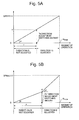
- Figs. 5A and 5B are graphs showing relationships between the amounts of operation of the pointing device 11 and the operating speeds thereof, which are detected by the sensing module 13.
- control of the pointing device and pointer corresponding thereto has a relationship (control characteristics) in which the speed of the object to be operated is accelerated as the amount of operation is increased.
- a direction adjustment switching amount Th is defined as a parameter (threshold value) between zero (reference point) of the amount of operation and the'maximum (Rmax) thereof, which are shown on an axis of abscissae.
- Th the amount of operation is less than this direction adjustment switching amount Th.
- the direction adjustment control is performed. Switching control using the direction adjustment switching amount Th as a reference is performed by the adjustment module 30.
- the detected operating speed is relatively rapid, it is expected that the user desires to move the object (pointer) to be controlled far in a shorter time. In such a case, an operation good at linearity can be realized.
- a direction adjustment switching amount Th' is defined as a threshold value for switching the control on the operating speed v shown in an axis of ordinates. Then, as in the above-described case, the direction adjustment control may be switched on and off in response to whether or not the operating speed detected by the sensing module 13 is larger than the direction adjustment switching amount Th'.
- the operating acceleration is represented by gradients of straight lines shown in the drawing.
- the control characteristics cause the acceleration of the pointing device 11 on the move to be changed from a to a'
- the operating acceleration a' at the start of adjustment is defined as a threshold value for switching the control (a direction adjustment switching amount Th'').
- the adjustment control may be switched on and off in response to whether or not the operating acceleration detected by the sensing module 13 is larger than the direction adjustment switching amount Th".
- Fig. 6 is the flowchart of the adjustment control of the pointing device pursued when the unadjusted circular range is set up in the control unit 203 of the cellular phone 1 according to this embodiment.
- Such a flowchart shows a processing procedure of the software programs executed by the CPU 200 of the control unit 203 in the cellular phone 1 shown in Fig. 1.
- the CPU 200 stores, in the operating memory 204, the display position (values of the abscissae and the ordinates in the coordinate system) of the pointer currently displayed on the display 208A, for example, by the function of the pointer display control module 36.
- the stored display position is referred to as a reference position in S703.
- the adjustment control shown in Fig. 6 is started, for example, in response to a power source of the cellular phone 1 being switched on by the user (S701).
- the CPU 200 first determines whether or not the pointing device 11 is operated by the user (S702). For the determination, an interrupt signal or the like which indicates that the pointing device 11 is operated is commonly used. Moreover, in many cases, although the pointing device 11 that is a unit to be operated, a region which does not react even if the pointing device 11 is somewhat moved is provided in order to allow a mechanical idleness.
- the CPU 200 calculates the operation state of the pointing device 11 (that is, information indicating the operation state) with the display position of the pointer at that time defined as the reference position (S703).
- the operation state is calculated by the CPU 200 executing the function of the.sensing module 13 described above.
- the operation state includes. the present operating direction, amount of operation, operating speed and operating acceleration of the pointing device 11.
- the CPU 200 determines whether or not the amount of operation calculated in S703 is equal to, or more than, the radius r of the unadjusted range circle 81, which is represented by the direction adjustment switching amount Th(Th') described above with reference to Figs. 5A and 5B (S704).
- the CPU 200 performs the direction adjustment control described above with reference to Fig. 3 and Figs. 4A to 4E (S705).
- the CPU 200 does not perform such direction adjustment control (S706).
- the CPU 200 performs processing in S707. Specifically, when the direction adjustment is performed in S705, the CPU 200 transfers the amount of operation calculated in S703, the operating direction subjected to the direction adjustment in S705 and the like to the pointer display control module 36. On the other hand, when the direction adjustment is not performed in S706, the CPU 200 transfers the amount of operation calculated in S703, the operating direction and the like, to the pointer display control module 36.
- the CPU 200 controls the display unit 208 based on the control information transferred from the adjustment module S707, and thus displays the pointer on an appropriate position on the display 208A.
- the processing flow is configured in such a manner that the above-described S702 to S707 are sequentially executed and the processing returns to S702 that is a start of the repetition. Usually, this repetition is performed at an arbitrary fixed intervals.
- Fig. 4D an example of the pattern obtained by synthesizing the unadjusted range circle 81 and the adjustment regions 72 shown in Fig. 4B is shown.
- the synthesis pattern is not limited to this.
- the pattern may be the adjustment regions 71 shown in Fig. 4A or may be one formed by synthesizing the adjustment regions 73 and 74 shown in Fig. 4C as well as the unadjusted range circle 81.
- a setting for the adjustment control to switch on and off the adjustment at a boundary defined by the radius r may be made, in which four adjustment directions 64 are switched to eight adjustment directions 65 at a boundary defined this radius r, these directions 64 and 65 being two stages in the switching.
- control for switching the number of adjustment directions is not limited to the switching from the four directions to the eight directions. Specifically, the number of adjustment directions may be increased or decreased according to needs.
- a pattern may be configured to perform the switching control for three stages or more.
- the resolution of the display or resolving power of the pointing device is different between a vertical (longitudinal) direction and a left-and-right (lateral) direction.
- a pattern may be set up as to be different between the adjustment regions in the vertical direction (in other words, the longitudinal direction, the fore-and-aft direction) and in the left-and-right direction.
- the adjustment region is not provided in some direction is also assumed.
- the operation range thereof is a circle or can be regarded as a circle in many cases. Therefore, in this embodiment described above, description has been made with recognition that the moving range (movable range) of the pointing device is the operation circle, and on the assumption that one direction adjustment range is shaped like a sector.
- the operation range and the shape of the adjustment range are not limited to those.
- a slight directional shift and the like between the actual operation of the pointing device 11 in the adjustment regions (adjustment regions 70 to 75 and 80) and the pointer (object to be controlled) displayed on the display 208A are adjusted to the proper adjustment directions (60 to 65) by means of the function of adjustment control program 35. Therefore, it is made possible to enhance the operability of the pointing device 1.
- the user can easily change the patterns of the adjustment regions, which are employed for the adjustment control.
- the user can change the comfortableness felt for the pointing device 11 according to his/her preference, and accordingly, this embodiment is good at adaptability.
- the present invention is not limited to each embodiment described above, and that each embodiment can be changed appropriately within the scope of the technical concept of the present invention.
- the present invention is not limited to application to a portable communications terminal device such as a cellular phone, and can be widely applied to a portable electronic instrument with a smaller casing, such as an information processing apparatus such as a game instrument and a PDA.
- the pointing device control apparatus is not limited to this device configuration. More specifically, for example, a mode of usage in which the pointing device is connected to an information processing apparatus such as a desktop personal computer and a game instrument is widespread. In such a mode of usage, it is assumed that the pointing device, the sensing module 13 and the adjustment module 30 are distributed separately from the information processing apparatus to which those are connected. Accordingly, in such a case, a program having at least the function of the adjustment module 30 is distributed through a recording medium or a communication line, or executed in the information processing apparatus, and thus the present invention will be configured.
- the object to be controlled is not limited to this.
- an operation of moving display positions of a variety of symbols for example, characters representing people, animals and the like, and the like.
- the present embodiment described based on the embodiment and the modification examples thereof, which are described above, is achieved by providing a computer program which can realize the function of the flowchart referred to in the description of the embodiment and the like to the cellular phone 1 described above, and by subsequently retrieving the computer programto the CPU 200 to execute the program. Moreover, in this case, it is satisfactory if the computer program provided to the apparatus may be stored in a storage device such as a readable/writable memory (the holding memory 205 and the like).
- a method of providing the computer program to the apparatus.concerned is not limited only to a method of installing the computer program to a computer or the like in production facilities before shipment thereof.
- a generally used procedure at present can be employed, such as a method of installing the program through a variety of recording media attachable/detachable onto/from a main body of the apparatus, and a method of downloading the program from the outside through a line of communications such as the Internet.
- the present invention is constituted of coding of such a computer program or a storage medium.
- the operability of the object to be controlled, which is to be operated can be enhanced even in a mounting environment where it is difficult to ensure a sufficient mounting area for the pointing device.
Landscapes
- Engineering & Computer Science (AREA)
- General Engineering & Computer Science (AREA)
- Theoretical Computer Science (AREA)
- Human Computer Interaction (AREA)
- Physics & Mathematics (AREA)
- General Physics & Mathematics (AREA)
- Position Input By Displaying (AREA)
Abstract
Description
- Example of linearly increasing the speed V in response to the amount of operation β (Fig. 8A);
- Examples in each of which a plurality of increasing gradients of the speed V are present (Figs. 8B to 8D);
- Examples of non-linear relationship between the amount of operation β and the speed V (Figs. 8E and 8F); and
- Example of the speed V constant with respect to the amount of operation β (Fig. 8G).
- An angle at the center of the adjustment region expressed by measure in radians;
- Information indicating a relationship between the angle at the center of measure in radians and the adjustment direction 60 (or information indicating the adjustment direction), and a radius R of the adjustment region;
- Number n of divided adjustment regions;
- Radius r of an unadjusted circular range;
- Operating speed v for start of the adjustment; and
- Operating acceleration a' for the start of the adjustment.
- Changing function to change the adjustment region 70
currently used to another adjustment region chosen out of the
plurality of adjustment regions stored in the holding
memory 205; - Synthesis function to synthesize the plurality of adjustment regions; and
- Control function to switch on/off the direction
adjustment function by the
adjustment control program 35 according to needs.
Claims (19)
- Apointing device control apparatus for controlling a position of an object to be controlled, the object being to be displayed on a display (208A) in response to an operation of a pointing device (11) by a user, characterized by comprising:settingmeans (31, 32, 34 and 203) for setting an adjustment region (70 to 75 and 80) and a predetermined direction (60 to 65) corresponding to the adjustment region with a movable range of the pointing device as an object to be adjusted, the movable range being treated as information based on a predetermined coordinate system in the control apparatus; andadjustment control means (35 and 203) for, when an actual operation direction (50 and 50') of the pointing device operated by the user is included in the adjustment region set by said setting means, adjusting information indicating the actual operation direction to information indicating the predetermined direction (60 to 65), which is set by the setting means so as to correspond to the adjustment region (70 to 75 and 80), in such a way that a moving direction of the object, the object being to be displayed on the display in response to the actual operation direction, to be controlled is changed to the predetermined direction.
- The pointing device control apparatus according to claim 1, characterized in that said setting means includes selection means (32) capable of choosing an adjustment region, the region being desired by the user and being to be employed for adjusting the actual operation direction, out of previously prepared plural types of the adjustment regions.
- The pointing device control apparatus according to any one of claims 1 and 2, characterized in that said setting means includes synthesis means (34) for synthesizing at least two types of the adjustment regions, the regions being chosen by the user out of the previously prepared plural types of adjustment regions, as the adjustment region, the region being to be employed for adjusting the actual operation direction.
- The pointing device control apparatus according to any one of claims 1 to 3, characterized in that said adjustment control means adjusts the information indicating the actual operation direction in order to adjust the actual operation direction to the predetermined direction when any of an amount of operation of the pointing device and an operating speed thereof is larger than a predetermined threshold value (Th).
- The pointing device control apparatus according to any one of claims 1 to 4, characterized in that said adjustment control means includes operation means capable of switching on and off the adjustment of the actual operation direction to the predetermined direction.
- The pointing device control apparatus according to claim 1, characterized in that a plurality of the adjustment regions are set up with a center position (0) of the movable range of the pointing device designated as a reference.
- The pointing device control apparatus according to claim 6, characterized in that the plurality of adjustment regions are made of at least two types of the adjustment regions (73 and 74) different in size from each other.
- The pointing device control apparatus according to claim 6, characterized in that, when the plurality of adjustment regions are set up within the movable range of the pointing device, the movable range includes an area where any adjustment region is not set up, the included region being set with the center position designated as the reference.
- The pointing device control apparatus according to claim 7, characterized in that, in the movable range of the pointing device, the at least two types of adjustment regions are different in size from each other in a longitudinal direction and in a lateral direction.
- The pointing device control apparatus according to claim 6, characterized in that each of the adjustment regions is shaped like a sector subtended by a predetermined angle at the center with the center position designated as the reference, and
the predetermined direction is a direction obtained by bisecting the angle at the center. - The pointing device control apparatus according to claim 1, characterized by further comprising:detection means (13) for detecting at least the actual operation direction of the pointing device.
- The pointing device control apparatus according to claim 4, characterized by further comprising:detection means (13) for detecting any of the amount of operation of the pointing device and the operating speed thereof as well as the actual operation direction.
- The pointing device control apparatus according to claim 1, characterized in that the pointing device is at least any one of a joystick, a pointing stick and a trackpad.
- An electronic instrument characterized by comprising the pointing device control apparatus according to any one of claims 1 to 13.
- The electronic instrument according to claim 14, characterized in that the electronic instrument is any of a cellular phone and a portable information terminal device (PDA).
- A pointing device control method for controlling a position of an object to be controlled, the object being to be displayed on a display (208A) in response to an operation of a user for a pointing device (11), the method characterized by comprising steps of:detecting at least an actual operation direction (50,50') of the pointing device operated by the user;setting up an adjustment region (70 to 75 and 80) and a predetermined direction (60 to 65) corresponding to the adjustment region with a movable range of the pointing device as an object to be adjusted, the movable range being treated as information based on a predetermined coordinate system in a control apparatus; andwhen the actual operation direction (50 and 50') of the pointing device detected in said detecting is included in the adjustment region set in said setting, adjusting information indicating the actual operation direction to information indicating the predetermined direction (60 to 65), which is set in said setting so as to correspond to the adjustment region (70 to 75 and 80), in such a way that a moving direction of the object to be controlled, the object being to be displayed on the display in response to the actual operation direction, is changed to the predetermined direction.
- The pointing device control method according to claim 16, characterized in that, in said adjusting, the information indicating the actual operation direction is adjusted (S704 and S705) in order to adjust the actual operation direction to the predetermined direction when any of an amount of operation of the pointing device and an operating speed thereof is larger than a predetermined threshold value (Th).
- A computer program for controlling operation of a pointing device control apparatus which controls a position of an object to be controlled, the object being to be displayed on a display (208A) in response to an operation by a user of a pointing device (11), the computer program characterized by causing a computer to realize:a setting function of setting up an adjustment region (70 to 75 and 80) and a predetermined direction (60 to 65) corresponding to the adjustment region with a movable range of the pointing device as an object to be adjusted, the movable range being treated as information based on a predetermined coordinate system in the control apparatus; andan adjustment control function of adjusting information indicating an actual operation direction (50 and 50') of operation of the pointing device by the user to information indicating the predetermined direction (60 to 65), which is set by said setting function so as to correspond to the adjustment region (70 to 75 and 80), in such a way that a moving direction of the obj ect to be controlled, the object being to be displayed on the display in response to the actual operation direction, is changed to the predetermined direction when the actual operation direction is included in the adjustment region.
- The computer program according to claim 18, characterized by further causing the computer to realize a detection function of detecting at least the actual operation direction of the pointing device.
Applications Claiming Priority (2)
| Application Number | Priority Date | Filing Date | Title |
|---|---|---|---|
| JP2003181325 | 2003-06-25 | ||
| JP2003181325A JP4269155B2 (en) | 2003-06-25 | 2003-06-25 | Pointing device control system and electronic device |
Publications (2)
| Publication Number | Publication Date |
|---|---|
| EP1501006A2 true EP1501006A2 (en) | 2005-01-26 |
| EP1501006A3 EP1501006A3 (en) | 2009-06-03 |
Family
ID=33487616
Family Applications (1)
| Application Number | Title | Priority Date | Filing Date |
|---|---|---|---|
| EP04014096A Withdrawn EP1501006A3 (en) | 2003-06-25 | 2004-06-16 | Apparatus, method and computer program for controlling a pointing device |
Country Status (4)
| Country | Link |
|---|---|
| US (1) | US7518595B2 (en) |
| EP (1) | EP1501006A3 (en) |
| JP (2) | JP4269155B2 (en) |
| CN (1) | CN100432906C (en) |
Cited By (1)
| Publication number | Priority date | Publication date | Assignee | Title |
|---|---|---|---|---|
| EP2348393B1 (en) * | 2009-12-28 | 2016-10-26 | Nintendo Co., Ltd. | Computer-readable storage medium having information processing program stored therein, information processing system, and information processing method |
Families Citing this family (28)
| Publication number | Priority date | Publication date | Assignee | Title |
|---|---|---|---|---|
| KR100590526B1 (en) * | 2003-04-18 | 2006-06-15 | 삼성전자주식회사 | Finger motion detection device and method |
| JP3734820B1 (en) | 2004-09-03 | 2006-01-11 | 任天堂株式会社 | GAME PROGRAM, GAME DEVICE, AND INPUT DEVICE |
| JP2006227784A (en) * | 2005-02-16 | 2006-08-31 | Nikon Corp | Electronics |
| JP4832826B2 (en) * | 2005-07-26 | 2011-12-07 | 任天堂株式会社 | Object control program and information processing apparatus |
| US7696985B2 (en) * | 2005-11-30 | 2010-04-13 | Avago Technologies Ecbu Ip (Singapore) Pte. Ltd. | Producing display control signals for handheld device display and remote display |
| JP5053735B2 (en) * | 2007-07-05 | 2012-10-17 | パイオニア株式会社 | Jog ball equipment |
| KR101430445B1 (en) * | 2007-08-20 | 2014-08-14 | 엘지전자 주식회사 | A terminal having a screen size adjustment function and a medium recording a program implementing the function |
| TW201027398A (en) * | 2009-01-09 | 2010-07-16 | E Lead Electronic Co Ltd | Method of controlling cursor with multiple and variable speeds through track pad |
| JP5216618B2 (en) * | 2009-02-04 | 2013-06-19 | 株式会社ゼンリンデータコム | Image display device, image display method, and computer program |
| TWI451293B (en) * | 2010-10-19 | 2014-09-01 | Elan Microelectronics Corp | Control method of multi - function controller |
| US9013398B2 (en) | 2010-10-19 | 2015-04-21 | Elan Microelectronics Corporation | Control methods for a multi-function controller |
| US8773473B2 (en) * | 2010-11-29 | 2014-07-08 | Microsoft Corporation | Instantaneous panning using a groove metaphor |
| US9411509B2 (en) | 2010-12-29 | 2016-08-09 | Microsoft Technology Licensing, Llc | Virtual controller for touch display |
| US9013264B2 (en) | 2011-03-12 | 2015-04-21 | Perceptive Devices, Llc | Multipurpose controller for electronic devices, facial expressions management and drowsiness detection |
| US9817494B2 (en) * | 2011-09-12 | 2017-11-14 | Mediatek Inc. | Method for converting control input of input domain into control output of control domain using variable control resolution technique, and related control apparatus thereof |
| TWI450128B (en) * | 2011-12-05 | 2014-08-21 | Wistron Corp | Gesture detecting method, gesture detecting system and computer readable storage medium |
| JP5641001B2 (en) | 2012-02-20 | 2014-12-17 | 株式会社デンソー | Display control apparatus and display system |
| TWI467467B (en) * | 2012-10-29 | 2015-01-01 | Pixart Imaging Inc | Method and apparatus for controlling object movement on screen |
| US9937416B2 (en) * | 2013-06-11 | 2018-04-10 | Microsoft Technology Licensing, Llc | Adaptive touch input controls |
| JP5843908B2 (en) * | 2014-03-07 | 2016-01-13 | 株式会社コナミデジタルエンタテインメント | GAME CONTROL DEVICE, GAME SYSTEM, AND PROGRAM |
| JP5790963B1 (en) * | 2014-09-02 | 2015-10-07 | 求 藤川 | Information processing apparatus, information processing method, and information processing program |
| AU2016100651B4 (en) | 2015-06-18 | 2016-08-18 | Apple Inc. | Device, method, and graphical user interface for navigating media content |
| US9652125B2 (en) | 2015-06-18 | 2017-05-16 | Apple Inc. | Device, method, and graphical user interface for navigating media content |
| US9990113B2 (en) | 2015-09-08 | 2018-06-05 | Apple Inc. | Devices, methods, and graphical user interfaces for moving a current focus using a touch-sensitive remote control |
| US9928029B2 (en) | 2015-09-08 | 2018-03-27 | Apple Inc. | Device, method, and graphical user interface for providing audiovisual feedback |
| KR20180051288A (en) * | 2016-11-08 | 2018-05-16 | 삼성전자주식회사 | Display apparatus and control method thereof |
| US11922006B2 (en) | 2018-06-03 | 2024-03-05 | Apple Inc. | Media control for screensavers on an electronic device |
| WO2023084755A1 (en) * | 2021-11-12 | 2023-05-19 | バルミューダ株式会社 | Schedule display device, schedule display program, and schedule display method |
Citations (4)
| Publication number | Priority date | Publication date | Assignee | Title |
|---|---|---|---|---|
| JPH05210461A (en) * | 1992-01-31 | 1993-08-20 | Sony Corp | Display device and remote control device for controlling display device |
| US5565887A (en) * | 1994-06-29 | 1996-10-15 | Microsoft Corporation | Method and apparatus for moving a cursor on a computer screen |
| JP2001005612A (en) * | 1999-06-04 | 2001-01-12 | Internatl Business Mach Corp <Ibm> | Pointer operation assist method |
| JP2003173239A (en) * | 2001-12-06 | 2003-06-20 | Matsushita Electric Ind Co Ltd | Portable information terminal device and screen display control method |
Family Cites Families (17)
| Publication number | Priority date | Publication date | Assignee | Title |
|---|---|---|---|---|
| JPS6111842A (en) * | 1984-06-26 | 1986-01-20 | Shimadzu Corp | image display device |
| JPS61198286A (en) * | 1985-02-28 | 1986-09-02 | ぺんてる株式会社 | Cursor control system |
| JPS63236128A (en) * | 1987-03-25 | 1988-10-03 | Toshiba Corp | Control system for moving speed of cursor display |
| JPH05265649A (en) | 1992-03-23 | 1993-10-15 | Nec Corp | Pointing device |
| JP3499000B2 (en) * | 1994-04-25 | 2004-02-23 | 武藤工業株式会社 | How to specify horizontal and vertical directions |
| US5877748A (en) * | 1995-11-20 | 1999-03-02 | Redlich; Sanford I. | Computer control input interface system |
| US6750877B2 (en) * | 1995-12-13 | 2004-06-15 | Immersion Corporation | Controlling haptic feedback for enhancing navigation in a graphical environment |
| US5745099A (en) * | 1995-12-18 | 1998-04-28 | Intergraph Corporation | Cursor positioning method |
| JPH09244808A (en) | 1996-03-04 | 1997-09-19 | Kansai Komunetsuto:Kk | Mouse cursor control method |
| JPH10154038A (en) * | 1996-11-21 | 1998-06-09 | Hudson Soft Co Ltd | Pointing input device |
| JP2001160336A (en) | 1999-12-01 | 2001-06-12 | Mazda Motor Corp | Operation switching device for vehicles |
| JP2003518284A (en) * | 1999-12-22 | 2003-06-03 | コーニンクレッカ フィリップス エレクトロニクス エヌ ヴィ | Pointer coordinate assignment |
| IL137690A (en) * | 2000-08-03 | 2004-09-27 | Marco Luzzatto | Apparatus for controlling computer pointer motions, outputs and events |
| CN1363880A (en) * | 2001-01-11 | 2002-08-14 | 张逶 | Information embedding technology |
| JP3909230B2 (en) * | 2001-09-04 | 2007-04-25 | アルプス電気株式会社 | Coordinate input device |
| US7092495B2 (en) * | 2001-12-13 | 2006-08-15 | Nokia Corporation | Communication terminal |
| US7109975B2 (en) * | 2002-01-29 | 2006-09-19 | Meta4Hand Inc. | Computer pointer control |
-
2003
- 2003-06-25 JP JP2003181325A patent/JP4269155B2/en not_active Expired - Fee Related
-
2004
- 2004-06-16 EP EP04014096A patent/EP1501006A3/en not_active Withdrawn
- 2004-06-23 US US10/873,458 patent/US7518595B2/en not_active Expired - Fee Related
- 2004-06-24 CN CNB2004100498437A patent/CN100432906C/en not_active Expired - Fee Related
-
2008
- 2008-11-28 JP JP2008304222A patent/JP5058954B2/en not_active Expired - Fee Related
Patent Citations (4)
| Publication number | Priority date | Publication date | Assignee | Title |
|---|---|---|---|---|
| JPH05210461A (en) * | 1992-01-31 | 1993-08-20 | Sony Corp | Display device and remote control device for controlling display device |
| US5565887A (en) * | 1994-06-29 | 1996-10-15 | Microsoft Corporation | Method and apparatus for moving a cursor on a computer screen |
| JP2001005612A (en) * | 1999-06-04 | 2001-01-12 | Internatl Business Mach Corp <Ibm> | Pointer operation assist method |
| JP2003173239A (en) * | 2001-12-06 | 2003-06-20 | Matsushita Electric Ind Co Ltd | Portable information terminal device and screen display control method |
Cited By (1)
| Publication number | Priority date | Publication date | Assignee | Title |
|---|---|---|---|---|
| EP2348393B1 (en) * | 2009-12-28 | 2016-10-26 | Nintendo Co., Ltd. | Computer-readable storage medium having information processing program stored therein, information processing system, and information processing method |
Also Published As
| Publication number | Publication date |
|---|---|
| JP2009080835A (en) | 2009-04-16 |
| CN100432906C (en) | 2008-11-12 |
| CN1577231A (en) | 2005-02-09 |
| US7518595B2 (en) | 2009-04-14 |
| JP4269155B2 (en) | 2009-05-27 |
| JP5058954B2 (en) | 2012-10-24 |
| JP2005018357A (en) | 2005-01-20 |
| US20040263472A1 (en) | 2004-12-30 |
| EP1501006A3 (en) | 2009-06-03 |
Similar Documents
| Publication | Publication Date | Title |
|---|---|---|
| US7518595B2 (en) | Pointing device control apparatus and method, electronic instrument, and computer program for the pointing device control apparatus | |
| US8024004B2 (en) | Device having display buttons and display method and medium for the device | |
| US8527902B2 (en) | Multidimensional volume and vibration controls for a handheld electronic device | |
| CN100378627C (en) | Pointing device and electronic equipment equipped with the same | |
| CN101578569B (en) | Control device, input device, control system, hand-held type information processng device, control method and its program | |
| JP7259045B2 (en) | Method, apparatus and computer program for viewing angle rotation | |
| EP2677741A1 (en) | Remote control apparatus and control method thereof | |
| JP2007510233A (en) | Human interface system | |
| US12474740B2 (en) | Electronic device comprising flexible display and operating method thereof | |
| CN108319418B (en) | A kind of interface display control method and mobile terminal | |
| JP2012252384A (en) | Screen control system, screen control method, and screen control program | |
| KR20030051665A (en) | Means for handheld functional apparatus | |
| WO2008050175A1 (en) | Method and apparatus for facilitating movement within a three dimensional graphical user interface | |
| CN111338529A (en) | Icon display method and electronic device | |
| CN111050073A (en) | Focusing method and electronic equipment | |
| CN108958697B (en) | Screen sound control method, device and electronic device | |
| US20070207834A1 (en) | Cellular communication terminals and methods that sense terminal movement for cursor control | |
| CN108111750B (en) | Zoom adjustment method, mobile terminal and computer readable storage medium | |
| WO2019042478A1 (en) | Control method for input method soft keyboard of mobile terminal, storage medium, and mobile terminal | |
| CN111338597A (en) | Display method and electronic device | |
| WO2007065734A2 (en) | Acceleration reference devices, cellular communication terminal systems, and methods that sense terminal movement for cursor control | |
| JP4450569B2 (en) | Pointer cursor control device and electronic apparatus equipped with the device | |
| CN108449490A (en) | A kind of terminal control method and terminal | |
| CN113608655A (en) | Information processing method, device, electronic equipment and storage medium | |
| CN108600957B (en) | Antenna control method and related products |
Legal Events
| Date | Code | Title | Description |
|---|---|---|---|
| PUAI | Public reference made under article 153(3) epc to a published international application that has entered the european phase |
Free format text: ORIGINAL CODE: 0009012 |
|
| AK | Designated contracting states |
Kind code of ref document: A2 Designated state(s): AT BE BG CH CY CZ DE DK EE ES FI FR GB GR HU IE IT LI LU MC NL PL PT RO SE SI SK TR |
|
| AX | Request for extension of the european patent |
Extension state: AL HR LT LV MK |
|
| PUAL | Search report despatched |
Free format text: ORIGINAL CODE: 0009013 |
|
| AK | Designated contracting states |
Kind code of ref document: A3 Designated state(s): AT BE BG CH CY CZ DE DK EE ES FI FR GB GR HU IE IT LI LU MC NL PL PT RO SE SI SK TR |
|
| AX | Request for extension of the european patent |
Extension state: AL HR LT LV MK |
|
| 17P | Request for examination filed |
Effective date: 20091201 |
|
| AKX | Designation fees paid |
Designated state(s): DE FR GB IT |
|
| 17Q | First examination report despatched |
Effective date: 20120119 |
|
| STAA | Information on the status of an ep patent application or granted ep patent |
Free format text: STATUS: THE APPLICATION IS DEEMED TO BE WITHDRAWN |
|
| 18D | Application deemed to be withdrawn |
Effective date: 20150327 |