EP1500870B1 - Lampe alimentée à l'énergie solaire - Google Patents
Lampe alimentée à l'énergie solaire Download PDFInfo
- Publication number
- EP1500870B1 EP1500870B1 EP04012171A EP04012171A EP1500870B1 EP 1500870 B1 EP1500870 B1 EP 1500870B1 EP 04012171 A EP04012171 A EP 04012171A EP 04012171 A EP04012171 A EP 04012171A EP 1500870 B1 EP1500870 B1 EP 1500870B1
- Authority
- EP
- European Patent Office
- Prior art keywords
- lamp
- light source
- holder
- solar
- solar cell
- Prior art date
- Legal status (The legal status is an assumption and is not a legal conclusion. Google has not performed a legal analysis and makes no representation as to the accuracy of the status listed.)
- Expired - Lifetime
Links
- 230000000694 effects Effects 0.000 description 4
- 230000006978 adaptation Effects 0.000 description 1
- 238000006243 chemical reaction Methods 0.000 description 1
- 230000001419 dependent effect Effects 0.000 description 1
- 238000011161 development Methods 0.000 description 1
- 230000018109 developmental process Effects 0.000 description 1
- 238000005286 illumination Methods 0.000 description 1
- 238000000034 method Methods 0.000 description 1
- 230000005855 radiation Effects 0.000 description 1
- 230000000630 rising effect Effects 0.000 description 1
- 239000012780 transparent material Substances 0.000 description 1
Images


Classifications
-
- F—MECHANICAL ENGINEERING; LIGHTING; HEATING; WEAPONS; BLASTING
- F21—LIGHTING
- F21V—FUNCTIONAL FEATURES OR DETAILS OF LIGHTING DEVICES OR SYSTEMS THEREOF; STRUCTURAL COMBINATIONS OF LIGHTING DEVICES WITH OTHER ARTICLES, NOT OTHERWISE PROVIDED FOR
- F21V17/00—Fastening of component parts of lighting devices, e.g. shades, globes, refractors, reflectors, filters, screens, grids or protective cages
- F21V17/02—Fastening of component parts of lighting devices, e.g. shades, globes, refractors, reflectors, filters, screens, grids or protective cages with provision for adjustment
-
- F—MECHANICAL ENGINEERING; LIGHTING; HEATING; WEAPONS; BLASTING
- F21—LIGHTING
- F21S—NON-PORTABLE LIGHTING DEVICES; SYSTEMS THEREOF; VEHICLE LIGHTING DEVICES SPECIALLY ADAPTED FOR VEHICLE EXTERIORS
- F21S8/00—Lighting devices intended for fixed installation
- F21S8/08—Lighting devices intended for fixed installation with a standard
- F21S8/081—Lighting devices intended for fixed installation with a standard of low-built type, e.g. landscape light
-
- F—MECHANICAL ENGINEERING; LIGHTING; HEATING; WEAPONS; BLASTING
- F21—LIGHTING
- F21S—NON-PORTABLE LIGHTING DEVICES; SYSTEMS THEREOF; VEHICLE LIGHTING DEVICES SPECIALLY ADAPTED FOR VEHICLE EXTERIORS
- F21S9/00—Lighting devices with a built-in power supply; Systems employing lighting devices with a built-in power supply
- F21S9/02—Lighting devices with a built-in power supply; Systems employing lighting devices with a built-in power supply the power supply being a battery or accumulator
- F21S9/03—Lighting devices with a built-in power supply; Systems employing lighting devices with a built-in power supply the power supply being a battery or accumulator rechargeable by exposure to light
- F21S9/035—Lighting devices with a built-in power supply; Systems employing lighting devices with a built-in power supply the power supply being a battery or accumulator rechargeable by exposure to light the solar unit being integrated within the support for the lighting unit, e.g. within or on a pole
-
- F—MECHANICAL ENGINEERING; LIGHTING; HEATING; WEAPONS; BLASTING
- F21—LIGHTING
- F21V—FUNCTIONAL FEATURES OR DETAILS OF LIGHTING DEVICES OR SYSTEMS THEREOF; STRUCTURAL COMBINATIONS OF LIGHTING DEVICES WITH OTHER ARTICLES, NOT OTHERWISE PROVIDED FOR
- F21V21/00—Supporting, suspending, or attaching arrangements for lighting devices; Hand grips
- F21V21/08—Devices for easy attachment to any desired place, e.g. clip, clamp, magnet
- F21V21/0824—Ground spikes
-
- F—MECHANICAL ENGINEERING; LIGHTING; HEATING; WEAPONS; BLASTING
- F21—LIGHTING
- F21V—FUNCTIONAL FEATURES OR DETAILS OF LIGHTING DEVICES OR SYSTEMS THEREOF; STRUCTURAL COMBINATIONS OF LIGHTING DEVICES WITH OTHER ARTICLES, NOT OTHERWISE PROVIDED FOR
- F21V21/00—Supporting, suspending, or attaching arrangements for lighting devices; Hand grips
- F21V21/14—Adjustable mountings
- F21V21/30—Pivoted housings or frames
-
- F—MECHANICAL ENGINEERING; LIGHTING; HEATING; WEAPONS; BLASTING
- F21—LIGHTING
- F21V—FUNCTIONAL FEATURES OR DETAILS OF LIGHTING DEVICES OR SYSTEMS THEREOF; STRUCTURAL COMBINATIONS OF LIGHTING DEVICES WITH OTHER ARTICLES, NOT OTHERWISE PROVIDED FOR
- F21V21/00—Supporting, suspending, or attaching arrangements for lighting devices; Hand grips
- F21V21/14—Adjustable mountings
- F21V21/26—Pivoted arms
- F21V21/28—Pivoted arms adjustable in more than one plane
- F21V21/29—Pivoted arms adjustable in more than one plane employing universal joints
-
- F—MECHANICAL ENGINEERING; LIGHTING; HEATING; WEAPONS; BLASTING
- F21—LIGHTING
- F21W—INDEXING SCHEME ASSOCIATED WITH SUBCLASSES F21K, F21L, F21S and F21V, RELATING TO USES OR APPLICATIONS OF LIGHTING DEVICES OR SYSTEMS
- F21W2131/00—Use or application of lighting devices or systems not provided for in codes F21W2102/00-F21W2121/00
- F21W2131/10—Outdoor lighting
- F21W2131/109—Outdoor lighting of gardens
-
- Y—GENERAL TAGGING OF NEW TECHNOLOGICAL DEVELOPMENTS; GENERAL TAGGING OF CROSS-SECTIONAL TECHNOLOGIES SPANNING OVER SEVERAL SECTIONS OF THE IPC; TECHNICAL SUBJECTS COVERED BY FORMER USPC CROSS-REFERENCE ART COLLECTIONS [XRACs] AND DIGESTS
- Y02—TECHNOLOGIES OR APPLICATIONS FOR MITIGATION OR ADAPTATION AGAINST CLIMATE CHANGE
- Y02B—CLIMATE CHANGE MITIGATION TECHNOLOGIES RELATED TO BUILDINGS, e.g. HOUSING, HOUSE APPLIANCES OR RELATED END-USER APPLICATIONS
- Y02B20/00—Energy efficient lighting technologies, e.g. halogen lamps or gas discharge lamps
- Y02B20/72—Energy efficient lighting technologies, e.g. halogen lamps or gas discharge lamps in street lighting
Definitions
- the invention relates to a solar-powered lamp, in particular for outdoor operation according to the preamble of patent claim 1.
- a solar lamp is disclosed with a spherical at least partially translucent lamp body whose solar cell carrier is pivotable to align the solar cells fixed on the solar cell carrier in the direction of the angle of incidence of the sun's rays.
- a variable-angle lockable joint is used to adjust the solar cell carrier.
- the solar lamp in this case comprises a cylindrical housing, in the lid of a plurality of solar cells, which form a solar cell array, are arranged.
- the solar cells are mounted on a support plate, on the underside, ie on the opposite side of the solar cells, an electronic control system is provided.
- the control electronics are fed by housed in the housing accumulators with power.
- the control electronics thus regulate the operation of the solar lamp, because the converted of the solar cells Energy of the daylight is stored in the accumulators.
- the operating state of the solar lamp changes to the effect that the control electronics change the Accumulators are electronically connected to the light emitting diodes, so that they serve as a light source.
- the housing of the solar lamp is fixedly mounted on a stick or post, which can be inserted, for example, in a lawn floor.
- This basic structure of a solar lamp is further developed according to DE 100 26 524 such that the solar cells are arranged in an inclined plane.
- the entire solar lamp has a columnar structure, in the head area, the solar cells are housed.
- the head area is rotatable relative to the pillar base rising on the floor. Consequently, the solar cells can be aligned in the direction of the sun.
- light sources are provided which radiate light through the transparent wall of the column.
- the joint is designed as a universal joint with at least two degrees of freedom.
- the light source and the solar cell receiving holder formed as separate components and connected via a respective joint with the pole of the solar lamp, these components can be individually tilted or pivoted from each other from the horizontal or the vertical plane.
- a rotation of these components about the longitudinal axis of the solar lamp is possible. Consequently, the solar cell field can be tracked in the course of the day and the different Clarstrahleinfallswinkel both in inclination and in its orientation the course of the sun.
- the light source which is designed, for example, as a radiator, on a particularly distinctive object, such as a shrubbery or the like, be aligned to illuminate this, completely independent of the positioning of the solar cell array.
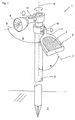
- FIG. 1 shows a solar-powered luminaire 1, in particular for outdoor operation, which is inserted with a post 3 in a floor 2, for example a lawn or a garden bed.
- the lamp 1 further comprises a holder 11, in which aligned in the direction of the sun, a plurality of solar cells 4 are attached.
- the solar cells 4 together form a solar cell array 5.
- control electronics and at least one accumulator are provided.
- the solar cells 4 convert the light energy into electrical energy and pass it on during the day, ie during the conversion process, to the accumulator, which stores the electrical energy.
- the control electronics establish an electrical connection between the accumulators and a light source 6 attached to the stanchion 3 made, so that now the trained as a radiator light source 6 achieves a luminous effect.
- the light source 6 and the holder 11 are movably secured by means of a respective joint 12 in the upper region of the post 3.
- the joint 12 relative ie about the vertical axis 9 of the post 3 are rotated.
- the joint 12 has a further degree of freedom, so that the angle of inclination of both the light source 6 and the holder 11 with respect to the vertical axis 9 of the post 3 can be pivoted.
- this pivotability or adjustability of the angle of inclination between the center axes 7 of the holder 11 and the center axis of the light source 6 is designated by the angle ⁇ or ⁇ .
- the holder 11 and the light source 6 are held pivotably in a ring 13.
- the ring 13 is in each case via the joint 12 in the same manner as the embodiment according to. Figure 1 connected to the post 3. It is possible to form the ring 13 as an outwardly open semicircle so that the light beams of the light source 6 as well as the solar radiation incident on the solar panel 5 sun rays are not hindered.
- the holder 11 ' is spherical and the post 3 has a cross-sectionally V-shaped receiving pocket, in which the holder 11' is firmly inserted. Between the V-shaped receiving pocket and the post 3, the hinge 12 is provided, so that the inclination angle of the holder 11 'from the vertical axis 9 can be adjusted inclined.
- the spherical holder 11 ' has in its interior an additional light source, not shown, so that the holder 11' can be illuminated.
- the holder 11 ' made of a transparent or semi-transparent material.
- FIG. 4 it can be seen that in the circumferential direction of the holder 11 ', a sliding block 16 is integrally formed on which at two positions, a bracket 14 surrounds this. Consequently, the bracket 14 can be moved in the circumferential direction of the holder 11 '. At the same time it is possible, the bracket 14, at the middle position, the light source 6 is mounted to pivot in any angular position about the two pivot points on the sliding blocks 16.
- the light source 6 can be aligned independently of the positioning of the solar cell array 5. This significantly increases the efficiency of the solar-powered lamp 1, because the solar panel 5 can be adjusted by adjusting the inclination be moved so that the sun's rays impinge more or less perpendicular to the solar cell array and therefore during the day a sufficiently large incidence of light is given.
- the light source 6 is designed as a radiator, by means of which an exact illumination of a particular object during the night can be made.
- the purpose and the efficiency of the solar powered lamp 1 is therefore significantly improved.
- the holder 11 is formed as a leaf of a flower or a tree.
- the light source 6 may represent a stylized flower of a plant, so that the lamp 1 causes a natural aesthetic effect effect.
Landscapes
- Engineering & Computer Science (AREA)
- General Engineering & Computer Science (AREA)
- Life Sciences & Earth Sciences (AREA)
- Sustainable Development (AREA)
- Photovoltaic Devices (AREA)
- Non-Portable Lighting Devices Or Systems Thereof (AREA)
- Illuminated Signs And Luminous Advertising (AREA)
- Liquid Crystal Substances (AREA)
- Cultivation Of Plants (AREA)
Claims (7)
- Lampe solaire (1), prévue notamment pour l'utilisation à l'air libre, comprenant une multitude de cellules solaires (4) insérées dans un support (11) et formant un champ de cellules solaires (5), ainsi qu'au moins une source de lumière (6) raccordée électriquement au champ de cellules solaires (5), où la source de lumière (6) et le support (11) portant le champ de cellules solaires (5), une électronique de commande ainsi qu'un ou plusieurs accumulateurs, est fixé à un poteau (3), à une barre ou à un dispositif similaire,
caractérisée en ce que
le support (11) du champ de cellules solaires (5) est conçu en tant que composant séparé qui se laisse aligner par rapport à la source de lumière (6), et que la source de lumière (6) et le support (11) s'appuient respectivement par l'intermédiaire d'une articulation (12) sur le poteau (3). - Lampe d'après la revendication 1,
caractérisée en ce que
l'articulation (12) est conçue sous la forme d'une articulation à cardan avec au moins deux degrés de liberté. - Lampe d'après la revendication 1 ou 2,
caractérisée en ce que
le support (11) et/ou la source de lumière (6) sont montés dans un anneau (13) qui se laisse tourner relativement au poteau (3). - Lampe d'après une ou plusieurs des revendications précédentes,
caractérisée en ce que
la source de lumière (6) est montée dans un étrier (14) et que l'étrier (14) est fixé sur le poteau (3) de sorte qu'il se laisse tourner et/ou incliner. - Lampe d'après une ou plusieurs des revendications précédentes,
caractérisée en ce que
le support (11) est conçu sous la forme d'une pétale d'une fleur, d'une feuille d'arbre etc. - Lampe d'après une ou plusieurs des revendications précédentes,
caractérisée en ce que
la source de lumière est conçue sous la forme d'un projecteur. - Lampe d'après une ou plusieurs des revendications précédentes,
caractérisée en ce
qu'il est prévu plusieurs champs de cellules solaires (5) fixés dans des supports (11) séparés l'un de l'autre.
Applications Claiming Priority (2)
| Application Number | Priority Date | Filing Date | Title |
|---|---|---|---|
| DE20311585U | 2003-07-25 | ||
| DE20311585U DE20311585U1 (de) | 2003-07-25 | 2003-07-25 | Solarbetriebene Leuchte |
Publications (2)
| Publication Number | Publication Date |
|---|---|
| EP1500870A1 EP1500870A1 (fr) | 2005-01-26 |
| EP1500870B1 true EP1500870B1 (fr) | 2006-08-30 |
Family
ID=29225427
Family Applications (1)
| Application Number | Title | Priority Date | Filing Date |
|---|---|---|---|
| EP04012171A Expired - Lifetime EP1500870B1 (fr) | 2003-07-25 | 2004-05-22 | Lampe alimentée à l'énergie solaire |
Country Status (3)
| Country | Link |
|---|---|
| EP (1) | EP1500870B1 (fr) |
| AT (1) | ATE338245T1 (fr) |
| DE (2) | DE20311585U1 (fr) |
Families Citing this family (21)
| Publication number | Priority date | Publication date | Assignee | Title |
|---|---|---|---|---|
| WO2005114043A1 (fr) * | 2004-05-14 | 2005-12-01 | Allsop, Inc. | Appareil d’eclairage exterieur solaire decale |
| ITPD20040198A1 (it) * | 2004-07-23 | 2004-10-23 | Lino Manfrotto & Co Spa | Supporto per apparecchiiature elettroniche, particolarmente di tipo video fotografico |
| US7891832B2 (en) | 2005-05-18 | 2011-02-22 | Allsop, Inc. | Outdoor light with positionable solar collector |
| GB0512984D0 (en) * | 2005-06-27 | 2005-08-03 | Bu Innovations Ltd | Pickable solar powered light |
| DE102007013129A1 (de) * | 2007-03-15 | 2008-09-25 | Stadtfeld Elektrotechnische Fabrik Gmbh & Co. Kg | Beleuchtungsvorrichtung, insbesondere netzunabhängige Beleuchtungsvorrichtung, und Beleuchtungsverbund |
| DE102007045119A1 (de) * | 2007-09-20 | 2009-04-02 | Trilux Gmbh & Co. Kg | Variabel einsetzbare Außenleuchte |
| WO2010122179A1 (fr) * | 2009-04-20 | 2010-10-28 | Siarq, S.L. | Système d'éclairage à alimentation photovoltaïque et intensité lumineuse programmable et réglable in situ ou à distance |
| WO2012065150A2 (fr) | 2010-11-13 | 2012-05-18 | Stephen Katsaros | Lampe à charge solaire ajustable |
| DE202012100891U1 (de) * | 2012-03-13 | 2013-06-14 | Steinel Gmbh | Leuchtenvorrichtung |
| WO2016119203A1 (fr) * | 2015-01-30 | 2016-08-04 | 凯灿贸易(深圳)有限公司 | Lampe laser solaire |
| ES2547469B1 (es) * | 2015-02-05 | 2016-06-22 | Alessandro CAVIASCA | Módulo fotovoltaico |
| BE1024073B1 (nl) * | 2015-12-23 | 2017-11-10 | Rik Hiergens | Verlichting voor toepassing in een tuin of in een plantrijke omgeving of dergelijke. |
| US9839088B1 (en) | 2016-03-10 | 2017-12-05 | Heathco, Llc | Security light with remote photo-voltaic module and battery backup and related methods |
| GR20160100153A (el) * | 2016-04-12 | 2017-11-30 | Ειρηνη Ευαγγελου Παπαδακη | Αυτονομο φωτιστικο με ηλιακο συλλεκτη |
| CN106678612A (zh) * | 2016-11-10 | 2017-05-17 | 成都朵猫文化传播有限公司 | 一种园林灯 |
| DE202018000444U1 (de) | 2018-01-18 | 2018-02-22 | Ronotic Ag | Solarleuchte |
| DE102018000677A1 (de) | 2018-01-18 | 2019-07-18 | Ronotic Ag | Solarleuchte |
| US11950677B2 (en) | 2019-02-28 | 2024-04-09 | L'oreal | Devices and methods for electrostatic application of cosmetics |
| US10718500B1 (en) | 2019-08-30 | 2020-07-21 | HealthCo LLC | Solar powered security light with variable mounting |
| CN110864260A (zh) * | 2019-12-04 | 2020-03-06 | 深圳市若盛科技有限公司 | 一种高实用性太阳能灯 |
| US11906133B2 (en) * | 2022-03-31 | 2024-02-20 | Alliance Sports Group, L.P. | Outdoor lighting apparatus |
Family Cites Families (8)
| Publication number | Priority date | Publication date | Assignee | Title |
|---|---|---|---|---|
| JPS639048Y2 (fr) * | 1980-07-16 | 1988-03-17 | ||
| US4977488A (en) * | 1990-03-14 | 1990-12-11 | Australux North America Ltd. | Solar powered outdoor recreational light with positionable solar panel |
| US6107941A (en) * | 1991-10-09 | 2000-08-22 | R. D. Jones, Right Of Way, Inc. | Traffic control system and kit |
| DE29521271U1 (de) * | 1995-05-03 | 1996-11-21 | Kämpf, Hartmut, 98529 Suhl | Autarke Beleuchtungseinrichtung für flächenhafte Werbeträger |
| DE29920735U1 (de) * | 1999-11-26 | 2000-05-25 | Trisl, Klaus, 65197 Wiesbaden | KT-Solarflächen-Träger mit kardanischer Aufhängung |
| DE10026524A1 (de) | 2000-05-27 | 2001-12-06 | Solar Trend Gmbh | Solarleuchte |
| DE10037237C2 (de) * | 2000-07-31 | 2003-05-15 | Zimmermann Gmbh Co Kg Rudolf | Solarleuchte mit einem im wesentlichen kugelförmigen, mindestens teilweise lichtdurchlässigen Leuchtenkörper |
| DE10201816A1 (de) | 2002-01-18 | 2003-07-31 | Wagner Gmbh J | Vorrichtung zur Umwandlung von Sonnenenergie |
-
2003
- 2003-07-25 DE DE20311585U patent/DE20311585U1/de not_active Expired - Lifetime
-
2004
- 2004-05-22 AT AT04012171T patent/ATE338245T1/de not_active IP Right Cessation
- 2004-05-22 DE DE502004001313T patent/DE502004001313D1/de not_active Expired - Fee Related
- 2004-05-22 EP EP04012171A patent/EP1500870B1/fr not_active Expired - Lifetime
Also Published As
| Publication number | Publication date |
|---|---|
| DE502004001313D1 (de) | 2006-10-12 |
| ATE338245T1 (de) | 2006-09-15 |
| EP1500870A1 (fr) | 2005-01-26 |
| DE20311585U1 (de) | 2003-10-09 |
Similar Documents
| Publication | Publication Date | Title |
|---|---|---|
| EP1500870B1 (fr) | Lampe alimentée à l'énergie solaire | |
| EP1514060B1 (fr) | Dispositif d'orientation automatique suivant la position du soleil | |
| DE69209586T2 (de) | Aussenleuchte mit veränderbarer Brennweite | |
| EP2166277A1 (fr) | Dispositif d'éclairage | |
| DE102005033777A1 (de) | Überdachung mit Beleuchtungseinrichtung | |
| DE102004013590B4 (de) | Solarkonzentrator mit mehreren Spiegeln | |
| DE202006015917U1 (de) | Solaranlage | |
| EP1852649A1 (fr) | Lampe de mât solaire | |
| DE102018002190A1 (de) | Leuchtenmast | |
| DE10037237C2 (de) | Solarleuchte mit einem im wesentlichen kugelförmigen, mindestens teilweise lichtdurchlässigen Leuchtenkörper | |
| EP3217074B1 (fr) | Éclairage extérieur modulaire | |
| DE8803720U1 (de) | Leuchte, insbesondere Straßenleuchte | |
| DE10129478C2 (de) | Solarmodul-/Verbraucheraggregat | |
| EP2639502B1 (fr) | Dispositif d'éclairage | |
| DE9015063U1 (de) | Außenleuchte | |
| DE102004026160B4 (de) | Beleuchtungssystem zur Erzeugung einer variablen Lichtverteilung | |
| DE10045028A1 (de) | Beleuchtungsanlage zur Simulation des Sonnenlichts | |
| DE10026524A1 (de) | Solarleuchte | |
| EP1273849A2 (fr) | Optique pour lampes d'intérieur | |
| DE202025107259U1 (de) | Außenleuchte | |
| DE102018000677A1 (de) | Solarleuchte | |
| DE19928857A1 (de) | Solarzellenanordnung | |
| DE202018000444U1 (de) | Solarleuchte | |
| DE102012018823A1 (de) | Vorrichtung zur Umgebungsbeleuchtung | |
| DE102007045120B4 (de) | Außenleuchte mit drehbarer Leuchtenabdeckung |
Legal Events
| Date | Code | Title | Description |
|---|---|---|---|
| PUAI | Public reference made under article 153(3) epc to a published international application that has entered the european phase |
Free format text: ORIGINAL CODE: 0009012 |
|
| AK | Designated contracting states |
Kind code of ref document: A1 Designated state(s): AT BE BG CH CY CZ DE DK EE ES FI FR GB GR HU IE IT LI LU MC NL PL PT RO SE SI SK TR |
|
| AX | Request for extension of the european patent |
Extension state: AL HR LT LV MK |
|
| 17P | Request for examination filed |
Effective date: 20050709 |
|
| AKX | Designation fees paid |
Designated state(s): AT BE BG CH CY CZ DE DK EE ES FI FR GB GR HU IE IT LI LU MC NL PL PT RO SE SI SK TR |
|
| GRAP | Despatch of communication of intention to grant a patent |
Free format text: ORIGINAL CODE: EPIDOSNIGR1 |
|
| GRAS | Grant fee paid |
Free format text: ORIGINAL CODE: EPIDOSNIGR3 |
|
| GRAA | (expected) grant |
Free format text: ORIGINAL CODE: 0009210 |
|
| AK | Designated contracting states |
Kind code of ref document: B1 Designated state(s): AT BE BG CH CY CZ DE DK EE ES FI FR GB GR HU IE IT LI LU MC NL PL PT RO SE SI SK TR |
|
| PG25 | Lapsed in a contracting state [announced via postgrant information from national office to epo] |
Ref country code: IT Free format text: LAPSE BECAUSE OF FAILURE TO SUBMIT A TRANSLATION OF THE DESCRIPTION OR TO PAY THE FEE WITHIN THE PRESCRIBED TIME-LIMIT;WARNING: LAPSES OF ITALIAN PATENTS WITH EFFECTIVE DATE BEFORE 2007 MAY HAVE OCCURRED AT ANY TIME BEFORE 2007. THE CORRECT EFFECTIVE DATE MAY BE DIFFERENT FROM THE ONE RECORDED. Effective date: 20060830 Ref country code: NL Free format text: LAPSE BECAUSE OF FAILURE TO SUBMIT A TRANSLATION OF THE DESCRIPTION OR TO PAY THE FEE WITHIN THE PRESCRIBED TIME-LIMIT Effective date: 20060830 Ref country code: IE Free format text: LAPSE BECAUSE OF FAILURE TO SUBMIT A TRANSLATION OF THE DESCRIPTION OR TO PAY THE FEE WITHIN THE PRESCRIBED TIME-LIMIT Effective date: 20060830 Ref country code: PL Free format text: LAPSE BECAUSE OF FAILURE TO SUBMIT A TRANSLATION OF THE DESCRIPTION OR TO PAY THE FEE WITHIN THE PRESCRIBED TIME-LIMIT Effective date: 20060830 Ref country code: RO Free format text: LAPSE BECAUSE OF FAILURE TO SUBMIT A TRANSLATION OF THE DESCRIPTION OR TO PAY THE FEE WITHIN THE PRESCRIBED TIME-LIMIT Effective date: 20060830 Ref country code: SK Free format text: LAPSE BECAUSE OF FAILURE TO SUBMIT A TRANSLATION OF THE DESCRIPTION OR TO PAY THE FEE WITHIN THE PRESCRIBED TIME-LIMIT Effective date: 20060830 Ref country code: SI Free format text: LAPSE BECAUSE OF FAILURE TO SUBMIT A TRANSLATION OF THE DESCRIPTION OR TO PAY THE FEE WITHIN THE PRESCRIBED TIME-LIMIT Effective date: 20060830 Ref country code: FI Free format text: LAPSE BECAUSE OF FAILURE TO SUBMIT A TRANSLATION OF THE DESCRIPTION OR TO PAY THE FEE WITHIN THE PRESCRIBED TIME-LIMIT Effective date: 20060830 Ref country code: CZ Free format text: LAPSE BECAUSE OF FAILURE TO SUBMIT A TRANSLATION OF THE DESCRIPTION OR TO PAY THE FEE WITHIN THE PRESCRIBED TIME-LIMIT Effective date: 20060830 Ref country code: GB Free format text: LAPSE BECAUSE OF FAILURE TO SUBMIT A TRANSLATION OF THE DESCRIPTION OR TO PAY THE FEE WITHIN THE PRESCRIBED TIME-LIMIT Effective date: 20060830 |
|
| REG | Reference to a national code |
Ref country code: GB Ref legal event code: FG4D Free format text: NOT ENGLISH |
|
| REG | Reference to a national code |
Ref country code: CH Ref legal event code: EP |
|
| REG | Reference to a national code |
Ref country code: IE Ref legal event code: FG4D Free format text: LANGUAGE OF EP DOCUMENT: GERMAN |
|
| REF | Corresponds to: |
Ref document number: 502004001313 Country of ref document: DE Date of ref document: 20061012 Kind code of ref document: P |
|
| PG25 | Lapsed in a contracting state [announced via postgrant information from national office to epo] |
Ref country code: SE Free format text: LAPSE BECAUSE OF FAILURE TO SUBMIT A TRANSLATION OF THE DESCRIPTION OR TO PAY THE FEE WITHIN THE PRESCRIBED TIME-LIMIT Effective date: 20061130 Ref country code: DK Free format text: LAPSE BECAUSE OF FAILURE TO SUBMIT A TRANSLATION OF THE DESCRIPTION OR TO PAY THE FEE WITHIN THE PRESCRIBED TIME-LIMIT Effective date: 20061130 Ref country code: BG Free format text: LAPSE BECAUSE OF FAILURE TO SUBMIT A TRANSLATION OF THE DESCRIPTION OR TO PAY THE FEE WITHIN THE PRESCRIBED TIME-LIMIT Effective date: 20061130 |
|
| PG25 | Lapsed in a contracting state [announced via postgrant information from national office to epo] |
Ref country code: ES Free format text: LAPSE BECAUSE OF FAILURE TO SUBMIT A TRANSLATION OF THE DESCRIPTION OR TO PAY THE FEE WITHIN THE PRESCRIBED TIME-LIMIT Effective date: 20061211 |
|
| PG25 | Lapsed in a contracting state [announced via postgrant information from national office to epo] |
Ref country code: PT Free format text: LAPSE BECAUSE OF FAILURE TO SUBMIT A TRANSLATION OF THE DESCRIPTION OR TO PAY THE FEE WITHIN THE PRESCRIBED TIME-LIMIT Effective date: 20070206 |
|
| NLV1 | Nl: lapsed or annulled due to failure to fulfill the requirements of art. 29p and 29m of the patents act | ||
| GBV | Gb: ep patent (uk) treated as always having been void in accordance with gb section 77(7)/1977 [no translation filed] |
Effective date: 20060830 |
|
| REG | Reference to a national code |
Ref country code: IE Ref legal event code: FD4D |
|
| EN | Fr: translation not filed | ||
| PLBE | No opposition filed within time limit |
Free format text: ORIGINAL CODE: 0009261 |
|
| STAA | Information on the status of an ep patent application or granted ep patent |
Free format text: STATUS: NO OPPOSITION FILED WITHIN TIME LIMIT |
|
| 26N | No opposition filed |
Effective date: 20070531 |
|
| BERE | Be: lapsed |
Owner name: J. WAGNER G.M.B.H. Effective date: 20070531 |
|
| PG25 | Lapsed in a contracting state [announced via postgrant information from national office to epo] |
Ref country code: MC Free format text: LAPSE BECAUSE OF NON-PAYMENT OF DUE FEES Effective date: 20070531 |
|
| PG25 | Lapsed in a contracting state [announced via postgrant information from national office to epo] |
Ref country code: BE Free format text: LAPSE BECAUSE OF NON-PAYMENT OF DUE FEES Effective date: 20070531 |
|
| PG25 | Lapsed in a contracting state [announced via postgrant information from national office to epo] |
Ref country code: GR Free format text: LAPSE BECAUSE OF FAILURE TO SUBMIT A TRANSLATION OF THE DESCRIPTION OR TO PAY THE FEE WITHIN THE PRESCRIBED TIME-LIMIT Effective date: 20061201 Ref country code: FR Free format text: LAPSE BECAUSE OF FAILURE TO SUBMIT A TRANSLATION OF THE DESCRIPTION OR TO PAY THE FEE WITHIN THE PRESCRIBED TIME-LIMIT Effective date: 20070511 |
|
| PG25 | Lapsed in a contracting state [announced via postgrant information from national office to epo] |
Ref country code: EE Free format text: LAPSE BECAUSE OF FAILURE TO SUBMIT A TRANSLATION OF THE DESCRIPTION OR TO PAY THE FEE WITHIN THE PRESCRIBED TIME-LIMIT Effective date: 20060830 |
|
| PGFP | Annual fee paid to national office [announced via postgrant information from national office to epo] |
Ref country code: AT Payment date: 20080521 Year of fee payment: 5 |
|
| PG25 | Lapsed in a contracting state [announced via postgrant information from national office to epo] |
Ref country code: FR Free format text: LAPSE BECAUSE OF FAILURE TO SUBMIT A TRANSLATION OF THE DESCRIPTION OR TO PAY THE FEE WITHIN THE PRESCRIBED TIME-LIMIT Effective date: 20060830 |
|
| PG25 | Lapsed in a contracting state [announced via postgrant information from national office to epo] |
Ref country code: LU Free format text: LAPSE BECAUSE OF NON-PAYMENT OF DUE FEES Effective date: 20070522 Ref country code: CY Free format text: LAPSE BECAUSE OF FAILURE TO SUBMIT A TRANSLATION OF THE DESCRIPTION OR TO PAY THE FEE WITHIN THE PRESCRIBED TIME-LIMIT Effective date: 20060830 |
|
| PG25 | Lapsed in a contracting state [announced via postgrant information from national office to epo] |
Ref country code: TR Free format text: LAPSE BECAUSE OF FAILURE TO SUBMIT A TRANSLATION OF THE DESCRIPTION OR TO PAY THE FEE WITHIN THE PRESCRIBED TIME-LIMIT Effective date: 20060830 Ref country code: HU Free format text: LAPSE BECAUSE OF FAILURE TO SUBMIT A TRANSLATION OF THE DESCRIPTION OR TO PAY THE FEE WITHIN THE PRESCRIBED TIME-LIMIT Effective date: 20070301 |
|
| PGFP | Annual fee paid to national office [announced via postgrant information from national office to epo] |
Ref country code: CH Payment date: 20090515 Year of fee payment: 6 |
|
| PGFP | Annual fee paid to national office [announced via postgrant information from national office to epo] |
Ref country code: DE Payment date: 20090625 Year of fee payment: 6 |
|
| PG25 | Lapsed in a contracting state [announced via postgrant information from national office to epo] |
Ref country code: AT Free format text: LAPSE BECAUSE OF NON-PAYMENT OF DUE FEES Effective date: 20090522 |
|
| REG | Reference to a national code |
Ref country code: CH Ref legal event code: PL |
|
| PG25 | Lapsed in a contracting state [announced via postgrant information from national office to epo] |
Ref country code: CH Free format text: LAPSE BECAUSE OF NON-PAYMENT OF DUE FEES Effective date: 20100531 Ref country code: LI Free format text: LAPSE BECAUSE OF NON-PAYMENT OF DUE FEES Effective date: 20100531 |
|
| PG25 | Lapsed in a contracting state [announced via postgrant information from national office to epo] |
Ref country code: DE Free format text: LAPSE BECAUSE OF NON-PAYMENT OF DUE FEES Effective date: 20101201 |