EP1852649A1 - Lampe de mât solaire - Google Patents
Lampe de mât solaire Download PDFInfo
- Publication number
- EP1852649A1 EP1852649A1 EP07002499A EP07002499A EP1852649A1 EP 1852649 A1 EP1852649 A1 EP 1852649A1 EP 07002499 A EP07002499 A EP 07002499A EP 07002499 A EP07002499 A EP 07002499A EP 1852649 A1 EP1852649 A1 EP 1852649A1
- Authority
- EP
- European Patent Office
- Prior art keywords
- mast
- housing
- lamp
- battery
- luminaire
- Prior art date
- Legal status (The legal status is an assumption and is not a legal conclusion. Google has not performed a legal analysis and makes no representation as to the accuracy of the status listed.)
- Withdrawn
Links
Images

Classifications
-
- F—MECHANICAL ENGINEERING; LIGHTING; HEATING; WEAPONS; BLASTING
- F21—LIGHTING
- F21S—NON-PORTABLE LIGHTING DEVICES; SYSTEMS THEREOF; VEHICLE LIGHTING DEVICES SPECIALLY ADAPTED FOR VEHICLE EXTERIORS
- F21S9/00—Lighting devices with a built-in power supply; Systems employing lighting devices with a built-in power supply
- F21S9/02—Lighting devices with a built-in power supply; Systems employing lighting devices with a built-in power supply the power supply being a battery or accumulator
- F21S9/03—Lighting devices with a built-in power supply; Systems employing lighting devices with a built-in power supply the power supply being a battery or accumulator rechargeable by exposure to light
- F21S9/037—Lighting devices with a built-in power supply; Systems employing lighting devices with a built-in power supply the power supply being a battery or accumulator rechargeable by exposure to light the solar unit and the lighting unit being located within or on the same housing
-
- F—MECHANICAL ENGINEERING; LIGHTING; HEATING; WEAPONS; BLASTING
- F21—LIGHTING
- F21V—FUNCTIONAL FEATURES OR DETAILS OF LIGHTING DEVICES OR SYSTEMS THEREOF; STRUCTURAL COMBINATIONS OF LIGHTING DEVICES WITH OTHER ARTICLES, NOT OTHERWISE PROVIDED FOR
- F21V21/00—Supporting, suspending, or attaching arrangements for lighting devices; Hand grips
- F21V21/10—Pendants, arms, or standards; Fixing lighting devices to pendants, arms, or standards
- F21V21/116—Fixing lighting devices to arms or standards
-
- F—MECHANICAL ENGINEERING; LIGHTING; HEATING; WEAPONS; BLASTING
- F21—LIGHTING
- F21S—NON-PORTABLE LIGHTING DEVICES; SYSTEMS THEREOF; VEHICLE LIGHTING DEVICES SPECIALLY ADAPTED FOR VEHICLE EXTERIORS
- F21S8/00—Lighting devices intended for fixed installation
- F21S8/08—Lighting devices intended for fixed installation with a standard
-
- F—MECHANICAL ENGINEERING; LIGHTING; HEATING; WEAPONS; BLASTING
- F21—LIGHTING
- F21W—INDEXING SCHEME ASSOCIATED WITH SUBCLASSES F21K, F21L, F21S and F21V, RELATING TO USES OR APPLICATIONS OF LIGHTING DEVICES OR SYSTEMS
- F21W2131/00—Use or application of lighting devices or systems not provided for in codes F21W2102/00-F21W2121/00
- F21W2131/10—Outdoor lighting
- F21W2131/103—Outdoor lighting of streets or roads
-
- F—MECHANICAL ENGINEERING; LIGHTING; HEATING; WEAPONS; BLASTING
- F21—LIGHTING
- F21Y—INDEXING SCHEME ASSOCIATED WITH SUBCLASSES F21K, F21L, F21S and F21V, RELATING TO THE FORM OR THE KIND OF THE LIGHT SOURCES OR OF THE COLOUR OF THE LIGHT EMITTED
- F21Y2115/00—Light-generating elements of semiconductor light sources
- F21Y2115/10—Light-emitting diodes [LED]
-
- Y—GENERAL TAGGING OF NEW TECHNOLOGICAL DEVELOPMENTS; GENERAL TAGGING OF CROSS-SECTIONAL TECHNOLOGIES SPANNING OVER SEVERAL SECTIONS OF THE IPC; TECHNICAL SUBJECTS COVERED BY FORMER USPC CROSS-REFERENCE ART COLLECTIONS [XRACs] AND DIGESTS
- Y02—TECHNOLOGIES OR APPLICATIONS FOR MITIGATION OR ADAPTATION AGAINST CLIMATE CHANGE
- Y02B—CLIMATE CHANGE MITIGATION TECHNOLOGIES RELATED TO BUILDINGS, e.g. HOUSING, HOUSE APPLIANCES OR RELATED END-USER APPLICATIONS
- Y02B20/00—Energy efficient lighting technologies, e.g. halogen lamps or gas discharge lamps
- Y02B20/72—Energy efficient lighting technologies, e.g. halogen lamps or gas discharge lamps in street lighting
Definitions
- the present invention relates to a solar-powered mast luminaire suitable for off-grid operation comprising a luminaire housing attachable to a mast, solar cells for the power supply of the lighting means, at least one battery for storing the solar power generated by the solar cells and a battery holder.
- a mast lamp of the aforementioned type is for example in the U.S. Patent 5,149,188 described.
- the luminaire housing is located at the front end of a comparatively long arm in the form of a horizontal arm.
- the plate-shaped modules with the solar cells are also mounted on this arm at some distance from the lamp housing with specially provided for this fastening devices.
- This arm in turn, with a vertical U-profile and an inclined support, forms a lighting unit mounted on a vertical mast with the arm and the inclined support respectively welded to the U-profile.
- the batteries for storing the energy generated by the solar cells are located in a separate cuboid housing having mounted plates with keyholes and can be hung in bolt-like fasteners that are located on the U-profile.
- the unit formed from the luminaire housing, the horizontal arm, the inclined support and the U-profile is quite bulky. Since the arm, the support and the U-profile are components made of metal, the unit also has a high weight. When mounting on an existing lamp posts corresponding tools are necessary and the handling of the large heavy unit is correspondingly expensive.
- the solar modules are also comparatively large plates whose placement in or on the lamp housing for this reason is technically impossible.
- the battery holder is far away from the lamp housing, so that correspondingly long cables for the power supply of the lamps must be pulled through the arm or the support to the lamp housing. An upgrade of an existing mast luminaire without solar module to the solar lamp is not provided in this known lamp and not solvable with reasonable effort in a technically meaningful way.
- the luminaire body is designed here as a hollow body in the form of a hemisphere in which the solar collectors are integrated.
- the batteries are also integrated into this hemispherical shape, with a battery layer of malleable and lightweight lithium accumulators serving as a battery.
- This solution is intended to create a solar lamp with aesthetically pleasing design.
- special malleable accumulators are needed in this known luminaire to integrate the batteries in the hemispherical shape, so that this solution is costly to manufacture.
- the object of the present invention is to provide a pole lamp of the type mentioned, which allows the use of commercially available batteries and solar cells and allows, with relatively little effort, a compact unit comprising the luminaire housing, battery, battery holder, lighting and solar cells on one for the luminaire provided mast or also to be attached to a conventional mast luminaire.
- At least one battery and / or the battery holder are arranged in or on the lamp housing and at least one flat planar solar cell is arranged in the region of a flat surface on the lamp housing.
- the solution according to the invention makes it possible, on the one hand, with a comparatively small installation effort, to produce a finished compact structural unit which contains all the components which are essential to the function and which is neither too great nor too heavy to attach to a lamppost.
- This unit contains in a compact form, the battery, if necessary, the battery holder, the lamps and the solar cells.
- This unit can, in principle, in one operation and save space on the lamppost and it is not necessary to mount the solar cells or the battery separately.
- the solar cells are flat and flat and are located on non-curved surfaces of the housing, so that commercially available solar cells can be used. Commercially available batteries can also be used.
- the solar cells are arranged on or in a housing hood, which is an upper part of the lamp housing. You can then, for example, put such a housing cover on an existing pole lamp. It is therefore possible in a particularly simple manner to convert a conventional lamp to a solar lamp according to the invention.
- the retrofitting of conventional lights without solar modules is therefore particularly cost-effective possible because of the solution according to the invention, because already existing components of the lamp can remain on the mast.
- the conversion kit usually includes only the housing cover with solar cells, a battery and / or a battery holder and a fastening device for attachment to a lamppost, and possibly also bulbs and / or electrical / electronic components for the operation of the lamp.
- a hole for a connection cable is still necessary, which is then connected to an electronic or electrical component in the conversion kit.
- a conversion kit of the type mentioned in claims 14 to 16 is also an object of the present invention.
- a preferred variant of the task solution according to the invention provides that the solar cells are arranged on the upper side and / or laterally on the housing cover.
- the solar cells can be welded, for example, in the preferably made of plastic housing cover.
- particularly flat plate-shaped solar cells with a low overall height (material thickness) are suitable.
- Lately quasi paper-thin crystalline silicon cells have become known, which are particularly suitable for this variant of the invention.
- the Fraunhofer Institute developed solar thin-film cells with the so-called LFC technology and an efficiency of, for example, 20%, which achieve a very high efficiency of charging voltage for the supply of the accumulators under low light conditions.
- These solar cells can according to the invention be combined with accumulators, which have a high storage capacity.
- so-called gel batteries are suitable for the purposes of the invention.
- a battery module is arranged with at least one battery in the interior of the lamp housing in a rear area facing the lamppost.
- one or more batteries are arranged on or on a battery holder, which is attachable by means of a fastening device on the lamppost.
- the luminaire housing has at least one connecting piece in a rear region, which is suitable for receiving a section of a tubular pole.
- two such nozzles are provided on the lamp housing, whose axes occupy an angle with each other, so that you can attach a lamp of the type according to the invention to various common types of masts with the usual dimensions, especially on vertical masts or on whip masts, in which the intended for the attachment of the lamp housing section extends approximately horizontally.
- a possible preferred variant of the invention provides that the battery holder is pivotable about a horizontal axis within a certain range relative to the fastening device. This has the advantage that during assembly, for example, on a whip mast can compensate for a horizontal mostly by a few degrees inclined position by pivoting, so that the batteries then occupy a horizontal position.
- the illustration shows an exemplary invention Mastaufsatztake in schematically simplified cross-section.
- the luminaire comprises an upper housing in the form of a hood 11 which is made, for example, of a UV-resistant plastic, e.g. PMMA exists.
- the preferably very thin solar cells can be welded, for example, in the plastic of the housing of the hood.
- Paper-thin crystalline silicon cells which may be arranged on the upper side and / or laterally on the housing, are particularly suitable in the context of the invention.
- connection cables of the individual components can be led to the terminals 12 to the electronics box 12 via a bore in the interior of the lamp.
- These components include a twilight switch 14 (DLR) as a light resistance, which serves to ensure a day / night operation.
- a battery module 13 is installed inside the lamp. This includes, for example, two dry batteries with 12 V / 27 Ah as energy storage, a console and a mast holder and will be explained later with reference to Figures 3 to 5.
- an approximately horizontally arranged mounting plate 18 is further installed, on the top side of the electronics box 12 is mounted. Below are at the Mounting plate 18, the bulbs 15 attached.
- the bulbs 15 attached.
- several rows of LEDs are provided in the form of light-emitting diode strips.
- the number of required LEDs depends on the desired illuminance and the type of light emitting diode.
- a pole-mounted luminaire of the type according to the invention which can be used as a street lamp, it is possible, for example, to provide 10 to 12 rows, each with a larger number of LEDs per row, for example 50 to 80 pieces per row.
- a number of about 720 to about 950 LEDs is recommended for this specific application in order to achieve the required illuminance, for example, 3.6 V and 20 mA per LED.
- each diode can be connected in series with a resistor assigned to them, in order to supply the light-emitting diodes at a total current consumption of, for example, 20 mA per LED row connected to 12 V in an energy-saving manner.
- the lamp further comprises a mirror reflector 17 for the light control, which is arranged below the mounting plate.
- This mirror reflector can also be omitted according to a variant of the invention, in which case the LED strips can be arranged so that they form a half-arc. It is advantageous if you achieve a light cone with a beam angle of 60 ° maximum to the ground in the road.
- a power transformer 16 is provided, which is housed in the embodiment of Figure 1 above the mounting plate 18 in the housing.
- the power transformer 16 is provided for example for an input voltage of 230 V AC and has an output voltage of 12 V DC and a power of 120 VA.
- the light emission takes place through the lamp glass 10, which is located below the hood 11, so that a light emission takes place downwards and towards the sides.
- the luminaire glass for example, consists of protective glass according to VDE 0100 with IP Class 68 and is watertight.
- FIG 2 shows a schematically simplified longitudinal section through the Mastaufsatztake invention.
- This is designed so that it can also be retrofitted to existing lamp posts or pole lights of different types.
- two pipe sockets 21 A and 21 B are arranged in the rear end region of the housing, of which the first 21 A allows an introduction of a vertical mast tube in the mounted state quasi from below into the attachment housing of the lamp according to the invention.
- the second port 21 B is arranged at right angles to it and virtually leaking horizontally from the housing to the rear, so that this second port 21 B a pipe holder for whip masts forms.
- the cable feed takes place in each case in the housing interior through the respective nozzle required, said cable feed 22 is indicated schematically in Figure 2 for the alternative with use of the first nozzle 21 A in its course.
- Figure 2 can be seen further arranged on the mounting plate 18 components, which were previously mentioned, namely the battery module 13, the power transformer 16, the electronics box 12, arranged in the front area inside the housing twilight switch 14.
- the mirror reflector 17 arranged illuminant 15 with the individual LED rows and the shape of the lamp glass 10 in longitudinal section. Also visible is the longitudinal sectional shape of the housing with the upper-side hood 11 of the housing, in which the thin solar cells are embedded, in particular welded.
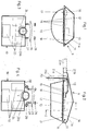
- a battery holder 19 which accommodates three batteries 20. These are preferably so-called gel batteries, which can be combined in one block and, for example, have a capacity of about 50 Ah.
- This battery holder can be connected according to the invention via a fastening device directly to the lamp posts 23 a, which has the advantage that thereby the lamp body is relieved of the relatively high weight of the batteries 20.
- the battery holder can, as you can see on the back have a recess 24 which receives the lamp posts 23 a.
- FIG. 4 An alternative way of attaching the battery holder 19 to an approximately horizontally extending portion of a lamp post 23 b (whip mast) is explained below with reference to the schematically simplified representation of Figure 4.
- section 23b of the lamppost shown in section thus extends approximately horizontally and the battery mount 19 to be fastened to the mast hangs almost below the mast.
- the viewing direction in FIG. 4 is therefore offset by approximately 90 ° from that in FIG. 3, ie FIG. 4 shows a view from the front, while FIG. 3 shows a plan view.
- the fastening device in Figure 4 comprises a mast clamp 25 and two fastening nut 26, as required, for example, threaded or wing nuts, which are each screwed onto threaded rods 27, which are located at a rear portion 28 of the battery holder.
- the mast clamp 25 includes the lamp posts 23 b. After attaching the battery holder 19 on the lamp masts 23 b, the weight of the batteries is transmitted to the masts.
- FIG. 5 shows a similar embodiment of the invention as in Figure 4 concerning the attachment to a whip mast.
- the illustration is also a schematically simplified side view of the attached to the lamp posts 23 b by means of mast clamp 25 and mounting nuts 26 battery holder 19.
- mast brackets 23 b is in the embodiment of a whip mast in which the mast tube lights side in a flat angle to the horizontal ends.
- the battery holder 19 is pivotable relative to the mast clip 25 about a horizontal axis 29, whereby it is possible to put the batteries in any horizontal position.
- the threaded rods 27 have an angular shape, so that, as can be seen in the drawing, a portion approximately in the direction of the pivot axis 29 extends and another portion, where each thread is, approximately at right angles thereto.
- the fastening nuts 26 are screwed, whereby the mast clamp 25, which surrounds the end portion of the mast tube of the lamp mast 23 b, is fixed. Because of this pivoting in the region of the connection between battery holder 19 and mast clamp 25, it is possible to align the battery holder with the batteries horizontally even when deviating from the horizontal orientation of the end portion.
- the whip pylons have a boom angle of 12 ° to the horizontal.
- FIG. 6 shows an exemplary circuit diagram for a pole-top luminaire according to the invention with solar operation.
- charging takes place via the solar cells 30 and the charging current flows via blocking diodes 31 to the rechargeable batteries 32.
- the discharge takes place via the charge controller 33 as a deep discharge, the circuit operating with an inverter 34, which has the advantage that the rechargeable battery 32 is in each case only a small amount of electricity is taken.
- In Connection with the transformer 35 used can be achieved, for example, a transmission ratio between the power consumption of the battery 32 and the current output to the board of 1:10.
- the contactor 37 closes the contact 36 and the power supply via the mains operation 38.
- the contacts 39, 40 are closed so that 12 V DC voltage applied to the Trapezcicrichter 34, whereby a 220 V AC voltage transformer 35 is activated.
- This converts to a 12 V AC voltage, which converts the downstream rectifier 41 into a 12 V DC voltage for feeding the LEDs.
Landscapes
- Engineering & Computer Science (AREA)
- General Engineering & Computer Science (AREA)
- Life Sciences & Earth Sciences (AREA)
- Sustainable Development (AREA)
- Non-Portable Lighting Devices Or Systems Thereof (AREA)
Priority Applications (1)
| Application Number | Priority Date | Filing Date | Title |
|---|---|---|---|
| EP07002499A EP1852649A1 (fr) | 2006-04-21 | 2007-02-06 | Lampe de mât solaire |
Applications Claiming Priority (2)
| Application Number | Priority Date | Filing Date | Title |
|---|---|---|---|
| PCT/EP2006/003681 WO2007121765A1 (fr) | 2006-04-21 | 2006-04-21 | Lampe autonome à énergie solaire, destinée à un lampadaire, se présentant sous forme d'unité complète ou d'ensemble d'équipement ultérieur |
| EP07002499A EP1852649A1 (fr) | 2006-04-21 | 2007-02-06 | Lampe de mât solaire |
Publications (1)
| Publication Number | Publication Date |
|---|---|
| EP1852649A1 true EP1852649A1 (fr) | 2007-11-07 |
Family
ID=38476835
Family Applications (1)
| Application Number | Title | Priority Date | Filing Date |
|---|---|---|---|
| EP07002499A Withdrawn EP1852649A1 (fr) | 2006-04-21 | 2007-02-06 | Lampe de mât solaire |
Country Status (1)
| Country | Link |
|---|---|
| EP (1) | EP1852649A1 (fr) |
Cited By (7)
| Publication number | Priority date | Publication date | Assignee | Title |
|---|---|---|---|---|
| WO2008059547A1 (fr) * | 2006-11-16 | 2008-05-22 | Enea-Ente Per Le Nuove Tecnologie L'energia E L'ambiente | Réverbère photovoltaïque multifonction à faible impact visuel |
| EP2101109A2 (fr) * | 2008-03-13 | 2009-09-16 | Andrew Johnson | Lampe sous-marine |
| NL2002149C (nl) * | 2008-10-29 | 2010-05-03 | Lightronics B V | Voor montage in een straatverlichtingsarmatuur ingerichte, van led's voorziene verlichtingseenheid. |
| WO2011045720A1 (fr) * | 2009-10-15 | 2011-04-21 | Koninklijke Philips Electronics N.V. | Dispositif d'éclairage comprenant une chambre de mélange |
| WO2011083186A1 (fr) * | 2010-01-07 | 2011-07-14 | Studio Itinerante Arquitectura, S.L. | Luminaire solaire photovoltaïque compact à autosuffisance énergétique |
| FR3019626A1 (fr) * | 2014-04-04 | 2015-10-09 | Servitronique | Support unique d'eclairage autonome integrant un panneau solaire |
| DE102020000956A1 (de) | 2020-02-11 | 2021-08-12 | Manuel Ehnes | Solar-Wendeltreppe |
Citations (9)
| Publication number | Priority date | Publication date | Assignee | Title |
|---|---|---|---|---|
| DE8810422U1 (de) * | 1988-08-18 | 1988-09-29 | Schroll, Stefan, Dipl.-Ing. (FH), 83365 Nußdorf | Gehäuse und Tragrahmen mit integrierter Spiegelkontur und Spiegelverstellvorrichtung für Leuchten |
| US5149188A (en) | 1991-04-01 | 1992-09-22 | Solar Outdoor Lighting, Inc. | Solar powered exterior lighting system |
| DE9419388U1 (de) * | 1994-12-07 | 1995-02-02 | Julius Cronenberg oHG, 59757 Arnsberg | Solarlichtkopf für Masten und Pfähle |
| EP0652401A2 (fr) * | 1993-08-19 | 1995-05-10 | Siemens Aktiengesellschaft | Lampadaire avec dispositif de fixation à un mât |
| DE20007434U1 (de) * | 2000-04-22 | 2000-07-20 | Hess Form & Licht Gmbh & Co | Lichtpoller |
| US6120165A (en) * | 1996-07-10 | 2000-09-19 | Solar Wide Industrial Ltd. | Outdoor solar lamp |
| DE202004009885U1 (de) * | 2004-06-23 | 2004-08-26 | Oblau, Wilfried | Solarbetriebenes Beleuchtungssystem |
| DE10336543A1 (de) | 2003-08-05 | 2005-03-17 | Russler, Theodor | Solarstromanlage |
| GB2408395A (en) * | 2003-11-24 | 2005-05-25 | Robert Francis Fray | Cylindrical solar street light |
-
2007
- 2007-02-06 EP EP07002499A patent/EP1852649A1/fr not_active Withdrawn
Patent Citations (9)
| Publication number | Priority date | Publication date | Assignee | Title |
|---|---|---|---|---|
| DE8810422U1 (de) * | 1988-08-18 | 1988-09-29 | Schroll, Stefan, Dipl.-Ing. (FH), 83365 Nußdorf | Gehäuse und Tragrahmen mit integrierter Spiegelkontur und Spiegelverstellvorrichtung für Leuchten |
| US5149188A (en) | 1991-04-01 | 1992-09-22 | Solar Outdoor Lighting, Inc. | Solar powered exterior lighting system |
| EP0652401A2 (fr) * | 1993-08-19 | 1995-05-10 | Siemens Aktiengesellschaft | Lampadaire avec dispositif de fixation à un mât |
| DE9419388U1 (de) * | 1994-12-07 | 1995-02-02 | Julius Cronenberg oHG, 59757 Arnsberg | Solarlichtkopf für Masten und Pfähle |
| US6120165A (en) * | 1996-07-10 | 2000-09-19 | Solar Wide Industrial Ltd. | Outdoor solar lamp |
| DE20007434U1 (de) * | 2000-04-22 | 2000-07-20 | Hess Form & Licht Gmbh & Co | Lichtpoller |
| DE10336543A1 (de) | 2003-08-05 | 2005-03-17 | Russler, Theodor | Solarstromanlage |
| GB2408395A (en) * | 2003-11-24 | 2005-05-25 | Robert Francis Fray | Cylindrical solar street light |
| DE202004009885U1 (de) * | 2004-06-23 | 2004-08-26 | Oblau, Wilfried | Solarbetriebenes Beleuchtungssystem |
Cited By (10)
| Publication number | Priority date | Publication date | Assignee | Title |
|---|---|---|---|---|
| WO2008059547A1 (fr) * | 2006-11-16 | 2008-05-22 | Enea-Ente Per Le Nuove Tecnologie L'energia E L'ambiente | Réverbère photovoltaïque multifonction à faible impact visuel |
| EP2101109A2 (fr) * | 2008-03-13 | 2009-09-16 | Andrew Johnson | Lampe sous-marine |
| EP2101109A3 (fr) * | 2008-03-13 | 2010-06-02 | Andrew Johnson | Lampe sous-marine |
| NL2002149C (nl) * | 2008-10-29 | 2010-05-03 | Lightronics B V | Voor montage in een straatverlichtingsarmatuur ingerichte, van led's voorziene verlichtingseenheid. |
| WO2011045720A1 (fr) * | 2009-10-15 | 2011-04-21 | Koninklijke Philips Electronics N.V. | Dispositif d'éclairage comprenant une chambre de mélange |
| WO2011083186A1 (fr) * | 2010-01-07 | 2011-07-14 | Studio Itinerante Arquitectura, S.L. | Luminaire solaire photovoltaïque compact à autosuffisance énergétique |
| EP2522900A1 (fr) * | 2010-01-07 | 2012-11-14 | Studio Itinerante Arquitectura, S.L. | Luminaire solaire photovoltaïque compact à autosuffisance énergétique |
| EP2522900B1 (fr) * | 2010-01-07 | 2018-05-09 | Studio Itinerante Arquitectura, S.L. | Luminaire solaire photovoltaïque compact à autosuffisance énergétique |
| FR3019626A1 (fr) * | 2014-04-04 | 2015-10-09 | Servitronique | Support unique d'eclairage autonome integrant un panneau solaire |
| DE102020000956A1 (de) | 2020-02-11 | 2021-08-12 | Manuel Ehnes | Solar-Wendeltreppe |
Similar Documents
| Publication | Publication Date | Title |
|---|---|---|
| EP1230513B1 (fr) | Lampe solaire pour usage en plein air | |
| DE69735284T2 (de) | Pfosten mit Solarzellen | |
| EP1852649A1 (fr) | Lampe de mât solaire | |
| DE20016549U1 (de) | Zier-Solarlampenbaueinheit | |
| DE102012008979A1 (de) | Beleuchtungssystem für Fahnenmasten, Masten, Stangen, Wimpel, Fahnen, Flaggen und Banner | |
| DE3940007C2 (de) | Signalleuchteneinrichtung | |
| DE10336543B4 (de) | Solarstromanlage | |
| EP2546570A2 (fr) | Lampe solaire | |
| DE10037237C2 (de) | Solarleuchte mit einem im wesentlichen kugelförmigen, mindestens teilweise lichtdurchlässigen Leuchtenkörper | |
| DE202010003952U1 (de) | Außenleuchte, insbesondere Straßenleuchte, sowie elektronischer Verbund von mehreren Außenleuchten | |
| DE29519098U1 (de) | Solarlichtkopf | |
| DE202006012244U1 (de) | Multifunktions-Mast | |
| DE202016103548U1 (de) | Mastwerbevorrichtung | |
| WO2007121765A1 (fr) | Lampe autonome à énergie solaire, destinée à un lampadaire, se présentant sous forme d'unité complète ou d'ensemble d'équipement ultérieur | |
| EP2639502B1 (fr) | Dispositif d'éclairage | |
| CH719039A9 (de) | Solare Baustellenwarnleuchte und Verfahren zum Betrieb einer Warnleuchte. | |
| EP3575673A1 (fr) | Luminaire extérieur | |
| AT508479B1 (de) | Lampe für eine dekorationsgirlande | |
| DE202016005734U1 (de) | Solareinheit | |
| CN210800772U (zh) | 一种照明工程施工用辅助工具 | |
| DE202018102989U1 (de) | Außenleuchte | |
| DE20110137U1 (de) | Lampe | |
| DE202014007017U1 (de) | Solarleuchte | |
| DE102019124556A1 (de) | Standby-unterstützung für ein zusatzgerät einer leuchte | |
| DE102016212099A1 (de) | Mastwerbevorrichtung |
Legal Events
| Date | Code | Title | Description |
|---|---|---|---|
| PUAI | Public reference made under article 153(3) epc to a published international application that has entered the european phase |
Free format text: ORIGINAL CODE: 0009012 |
|
| AK | Designated contracting states |
Kind code of ref document: A1 Designated state(s): AT BE BG CH CY CZ DE DK EE ES FI FR GB GR HU IE IS IT LI LT LU LV MC NL PL PT RO SE SI SK TR |
|
| AX | Request for extension of the european patent |
Extension state: AL BA HR MK YU |
|
| AKX | Designation fees paid |
Designated state(s): AT BE BG CH CY CZ DE DK EE ES FI FR GB GR HU IE IS IT LI LT LU LV MC NL PL PT RO SE SI SK TR |
|
| STAA | Information on the status of an ep patent application or granted ep patent |
Free format text: STATUS: THE APPLICATION IS DEEMED TO BE WITHDRAWN |
|
| 18D | Application deemed to be withdrawn |
Effective date: 20080508 |