EP1514060B1 - Dispositif d'orientation automatique suivant la position du soleil - Google Patents
Dispositif d'orientation automatique suivant la position du soleil Download PDFInfo
- Publication number
- EP1514060B1 EP1514060B1 EP02754271A EP02754271A EP1514060B1 EP 1514060 B1 EP1514060 B1 EP 1514060B1 EP 02754271 A EP02754271 A EP 02754271A EP 02754271 A EP02754271 A EP 02754271A EP 1514060 B1 EP1514060 B1 EP 1514060B1
- Authority
- EP
- European Patent Office
- Prior art keywords
- pivot
- base
- sun position
- rotary
- means according
- Prior art date
- Legal status (The legal status is an assumption and is not a legal conclusion. Google has not performed a legal analysis and makes no representation as to the accuracy of the status listed.)
- Expired - Lifetime
Links
Images


Classifications
-
- G—PHYSICS
- G01—MEASURING; TESTING
- G01J—MEASUREMENT OF INTENSITY, VELOCITY, SPECTRAL CONTENT, POLARISATION, PHASE OR PULSE CHARACTERISTICS OF INFRARED, VISIBLE OR ULTRAVIOLET LIGHT; COLORIMETRY; RADIATION PYROMETRY
- G01J1/00—Photometry, e.g. photographic exposure meter
- G01J1/02—Details
- G01J1/04—Optical or mechanical part supplementary adjustable parts
- G01J1/0403—Mechanical elements; Supports for optical elements; Scanning arrangements
-
- F—MECHANICAL ENGINEERING; LIGHTING; HEATING; WEAPONS; BLASTING
- F24—HEATING; RANGES; VENTILATING
- F24S—SOLAR HEAT COLLECTORS; SOLAR HEAT SYSTEMS
- F24S30/00—Arrangements for moving or orienting solar heat collector modules
- F24S30/40—Arrangements for moving or orienting solar heat collector modules for rotary movement
- F24S30/45—Arrangements for moving or orienting solar heat collector modules for rotary movement with two rotation axes
- F24S30/452—Vertical primary axis
-
- F—MECHANICAL ENGINEERING; LIGHTING; HEATING; WEAPONS; BLASTING
- F24—HEATING; RANGES; VENTILATING
- F24S—SOLAR HEAT COLLECTORS; SOLAR HEAT SYSTEMS
- F24S50/00—Arrangements for controlling solar heat collectors
- F24S50/20—Arrangements for controlling solar heat collectors for tracking
-
- G—PHYSICS
- G01—MEASURING; TESTING
- G01J—MEASUREMENT OF INTENSITY, VELOCITY, SPECTRAL CONTENT, POLARISATION, PHASE OR PULSE CHARACTERISTICS OF INFRARED, VISIBLE OR ULTRAVIOLET LIGHT; COLORIMETRY; RADIATION PYROMETRY
- G01J1/00—Photometry, e.g. photographic exposure meter
- G01J1/02—Details
- G01J1/04—Optical or mechanical part supplementary adjustable parts
-
- G—PHYSICS
- G01—MEASURING; TESTING
- G01J—MEASUREMENT OF INTENSITY, VELOCITY, SPECTRAL CONTENT, POLARISATION, PHASE OR PULSE CHARACTERISTICS OF INFRARED, VISIBLE OR ULTRAVIOLET LIGHT; COLORIMETRY; RADIATION PYROMETRY
- G01J1/00—Photometry, e.g. photographic exposure meter
- G01J1/42—Photometry, e.g. photographic exposure meter using electric radiation detectors
- G01J1/4228—Photometry, e.g. photographic exposure meter using electric radiation detectors arrangements with two or more detectors, e.g. for sensitivity compensation
-
- H—ELECTRICITY
- H02—GENERATION; CONVERSION OR DISTRIBUTION OF ELECTRIC POWER
- H02S—GENERATION OF ELECTRIC POWER BY CONVERSION OF INFRARED RADIATION, VISIBLE LIGHT OR ULTRAVIOLET LIGHT, e.g. USING PHOTOVOLTAIC [PV] MODULES
- H02S20/00—Supporting structures for PV modules
- H02S20/30—Supporting structures being movable or adjustable, e.g. for angle adjustment
- H02S20/32—Supporting structures being movable or adjustable, e.g. for angle adjustment specially adapted for solar tracking
-
- F—MECHANICAL ENGINEERING; LIGHTING; HEATING; WEAPONS; BLASTING
- F24—HEATING; RANGES; VENTILATING
- F24S—SOLAR HEAT COLLECTORS; SOLAR HEAT SYSTEMS
- F24S30/00—Arrangements for moving or orienting solar heat collector modules
- F24S2030/10—Special components
- F24S2030/13—Transmissions
- F24S2030/134—Transmissions in the form of gearings or rack-and-pinion transmissions
-
- F—MECHANICAL ENGINEERING; LIGHTING; HEATING; WEAPONS; BLASTING
- F24—HEATING; RANGES; VENTILATING
- F24S—SOLAR HEAT COLLECTORS; SOLAR HEAT SYSTEMS
- F24S30/00—Arrangements for moving or orienting solar heat collector modules
- F24S2030/10—Special components
- F24S2030/14—Movement guiding means
-
- G—PHYSICS
- G01—MEASURING; TESTING
- G01J—MEASUREMENT OF INTENSITY, VELOCITY, SPECTRAL CONTENT, POLARISATION, PHASE OR PULSE CHARACTERISTICS OF INFRARED, VISIBLE OR ULTRAVIOLET LIGHT; COLORIMETRY; RADIATION PYROMETRY
- G01J1/00—Photometry, e.g. photographic exposure meter
- G01J1/02—Details
- G01J1/0204—Compact construction
-
- Y—GENERAL TAGGING OF NEW TECHNOLOGICAL DEVELOPMENTS; GENERAL TAGGING OF CROSS-SECTIONAL TECHNOLOGIES SPANNING OVER SEVERAL SECTIONS OF THE IPC; TECHNICAL SUBJECTS COVERED BY FORMER USPC CROSS-REFERENCE ART COLLECTIONS [XRACs] AND DIGESTS
- Y02—TECHNOLOGIES OR APPLICATIONS FOR MITIGATION OR ADAPTATION AGAINST CLIMATE CHANGE
- Y02E—REDUCTION OF GREENHOUSE GAS [GHG] EMISSIONS, RELATED TO ENERGY GENERATION, TRANSMISSION OR DISTRIBUTION
- Y02E10/00—Energy generation through renewable energy sources
- Y02E10/40—Solar thermal energy, e.g. solar towers
- Y02E10/47—Mountings or tracking
-
- Y—GENERAL TAGGING OF NEW TECHNOLOGICAL DEVELOPMENTS; GENERAL TAGGING OF CROSS-SECTIONAL TECHNOLOGIES SPANNING OVER SEVERAL SECTIONS OF THE IPC; TECHNICAL SUBJECTS COVERED BY FORMER USPC CROSS-REFERENCE ART COLLECTIONS [XRACs] AND DIGESTS
- Y02—TECHNOLOGIES OR APPLICATIONS FOR MITIGATION OR ADAPTATION AGAINST CLIMATE CHANGE
- Y02E—REDUCTION OF GREENHOUSE GAS [GHG] EMISSIONS, RELATED TO ENERGY GENERATION, TRANSMISSION OR DISTRIBUTION
- Y02E10/00—Energy generation through renewable energy sources
- Y02E10/50—Photovoltaic [PV] energy
Definitions
- the present invention relates to an automatically acting Claritiesnach2020 estradiol.
- the present invention has for its object to provide a self-acting Sonnenstandsnach2020 adopted for solar modules, which is characterized by a compact and robust design with low maintenance requirements.
- the inventively designed Claresnachdies 1935 can be attached to a stationary or a movable part. In a particularly preferred manner, it serves for attachment to a vehicle, for example a caravan or a mobile home, in particular on the roof thereof.
- the solar module or the solar modules can take over the power supply of the motorhome or caravan.
- the inventively designed Claritiesnachdies has a base for attachment to the stationary or movable part and a rotatably mounted on the base and driven by a rotary drive turntable.
- the rotary drive which is controlled by the control unit, there is a rotation of the turntable and thus of the solar module or the solar modules by one vertical axis of rotation.
- On the turntable is a pivoting frame, which can be swung open and is brought via a rotary actuator in the appropriate pivoting position.
- On the pivoting frame of the solar module or the solar modules are attached. The pivoting frame can be moved from a position parallel to the turntable (with a pivoting angle of 0 °) to a pivoted position of about 90 ° and back again.
- the pivoting frame has a fixedly connected to the turntable and an element pivotally mounted thereto pivoting element, which carries the solar module or the solar modules.
- the pivot drive which is arranged in the end region of the fixedly connected to the turntable element, in the end region in which the pivot bearing is provided between the two elements, not substantially over the top of the fixedly connected to the turntable element protrudes, so that over the entire length of the elements solar modules can be arranged and overall low height is achieved in which project no mechanical parts in the swung-up state upwards.
- this reduces the forces acting on the device wind forces, which is particularly important in the attachment of Sonnenstandsnachhow on the roof of a vehicle of importance.
- the pivot drive is mounted on the fixedly connected to the turntable element transversely to the axis thereof (longitudinal axis) and includes a motor, a reduction gear and provided with a toothed transmission output shaft, with which meshes with a sector gear connected to the pivot member of the pivot frame.
- the sector gear is designed and arranged so that it does not project beyond the pivoting element upwards. This would be the case with a normally formed full circle gear.
- the motor (electric motor) of the rotary actuator When the motor (electric motor) of the rotary actuator is activated, its shaft is set in revolutions.
- the gear used is a reduction, preferably in about a ratio of 1: 180.
- the transmission output shaft therefore rotates much slower than the motor shaft and pivots the meshing with her sector gear and thus the pivoting element with the attached solar module (solar modules).
- the sector gear preferably spans an arc of about 120 °, i. a third circle.
- the desired pivoting of the pivot member can be achieved by at least 90 °, without the sector gear projecting above the elements and makes the attachment of solar modules in this area impossible.
- the pivoting element is mounted with sector gear between two fixedly connected to the turntable elements swiveling.
- Engine, reduction gear and transmission output shaft are suitably mounted on two fixedly connected to turntable elements, which have between them the teeth of the transmission output shaft. This also achieves a robust design of the rotary actuator.
- the pivoting frame normally extends laterally beyond the turntable.
- the elements are formed as rods, that is, the pivoting frame in this case comprises at least one fixed to the turntable connected rod and at least one pivot rod.
- the device comprises a total of four fixedly connected to the turntable rods, of which the two outer are each pivotally connected to a pivot rod and the two inner pivotally connected to the sector gear having the pivot rod.
- two solar panels are fixed to the pivot rods, which provide the connection between the driven pivot rod (provided with the sector gear pivot rod) and the other two pivot rods.
- Swivel frame, rotary actuator and turntable thus form a rotatably mounted on the base unit.
- the turntable is rotatably mounted on the base by means of balls arranged in an annular groove.
- the substructure is preferably composed of a base plate, a housing arranged thereon and a fixed plate arranged thereon for supporting the turntable.
- the annular groove is half in the fixed plate and arranged in the turntable.
- the base plate can be connected, for example, by screwing, gluing etc. with the roof of a vehicle (motorhome, caravan).
- a motor electric motor
- a reduction gear and a drive worm, which meshes with a drive gear for the turntable.
- the drive gear is connected to a hollow hub, which extends through the fixed plate and is connected to the turntable.
- the optical sensor is preferably arranged on the solar module (solar panel).
- the pivoting frame carries two solar panels, of which the upper in the pivoting position carries the opto-sensor.
- the optical sensor and the limit switches for the rotary drive and rotary actuator supply corresponding signals to a control unit (CPU), which controls the two motors for the rotary actuator and rotary drive and is in operative connection with a control panel with display that at least a manual switching on and off of the device allows and, for example, has a display with LEDs that indicates the correct position of the device relative to the state of the sun.
- CPU control unit
- This embodiment is based on the idea of providing, with the separating device arranged on the substructure, a device which casts shadows depending on the position of the sun, covering one compartment or several compartments and thus the at least one light receiving device arranged in each compartment.
- the separator can produce no shadow at all, if the sun is exactly vertical above the sensor and thus the separator or if otherwise uniform lighting conditions are present, such as at night, in diffused light, etc., or the separator can cast shadows if their longitudinal axis forms an angle with the axis corresponding to the position of the sun.
- one or more compartments and thus the corresponding light receiving means of the associated compartments are covered by the shadow generated by the divider and thus do not generate electrical signals while the other compartments and associated light receiving means are shadowless and generate electrical signals.
- the electrical signals are supplied to a control unit which operates in response to the received signals the rotary drive and / or rotary actuator, which track the solar module relative to the position of the sun, i. bring in an optimal position to the sun, in which the sun's rays approximately perpendicular to the solar module surface (solar panel surface) impinge. It is understood that the corresponding electrical signals are evaluated in a suitable manner before they fulfill their control functions.
- the separator for example, aligned so that the axis of the sensor and the Separating device at the highest level of the sun (twelve noon) runs exactly parallel to the sun's rays, in this case, with appropriate sun exposure, all light receiving devices in operation and indicate the optimum position of the sun. A movement of a corresponding solar module is therefore not required. If the angle of the solar radiation relative to the axis of the sensor now changes, the separating device casts shade on one or more compartments, so that one or more light receiving devices are put out of operation, which, as explained above, is indicated or leads to a tracking of the corresponding solar module until the optimal position is reached again.
- the separator divides the space above the base into four compartments. It forms a so-called “shadow cross" with which particularly good results have been achieved with respect to the functionality of the sensor.
- a light receiving device is arranged in each compartment. This arrangement is sufficient to provide sufficiently accurate display and control.
- a light receiving device is preferably a photodiode use.
- the senor has an approximately square in horizontal section base and a separator with arranged along the diagonal of the base walls.
- the separator therefore forms a "shadow cross", which corresponds in horizontal section about a St. Andrew's Cross.
- the photodiodes are fixed on the substructure, whereby the corresponding electrical lines unite within the substructure and are led out of the substructure via an electrical cable.
- the cable communicates with a suitable control / evaluation / display unit.
- the sensor is expediently provided on the rotatably and pivotally arranged solar module itself, i. he is each moved in the optimal position of the solar module relative to the sun. As a result, the position of the sensor always corresponds exactly to the position of the solar module.
- control unit If all light receiving devices are illuminated equally bright (in sunlight, scattered light, at night), the associated control unit generates no commands for tracking the solar module. Such control commands are only generated when brightness differences between the individual compartments (light receiving devices) occur. When such a difference occurs, both drives, i. the rotary drive and rotary actuator driven (in zigzag) to achieve a vertical position of the sun.
- a control unit is preferably provided with a device for vibration suppression in order to avoid a permanent reciprocation of the drives.
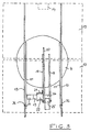
- the self-acting Claridish Pigsnachterrorism a base, which consists of a bottom plate 1, a housing 2 and a housing 3 arranged on the plate.
- a turntable 4 which carries a pivoting frame 31, are attached to the two solar panels 13.
- These solar panels 13 convert sunlight into electrical current, which can serve, for example, to supply a vehicle on the roof of which the device is arranged.
- the bottom plate 1 is glued or screwed to the roof of the vehicle.
- signals generated are a rotary drive for rotating the turntable 4 and a pivot drive for opening and pivoting the pivoting frame 31 is actuated to set an optimal state of the solar panels 13 to the sun (vertical incidence of the sun's rays on the panel level).
- the rotary drive for rotating the turntable 4.
- the rotary drive comprises an electric motor 16, a reduction gear 15 and a drive screw 9, which are arranged along an axis.
- the worm 9 meshes with a drive gear 8 which is fixedly connected to a hollow hub 7.
- the hollow hub extends through the fixed plate 3 upwards and is firmly connected to the turntable 4.
- a rotation of the drive gear 8 generated by the drive screw 9 thus causes a rotation of the turntable 4.
- the turntable 4 is mounted on the fixed plate 3 via balls 5, wherein the balls are housed in an annular groove 6, which are in half in two plates 3, 4 extends.
- the rotation of the drive gear 8 is limited by limit switches 18, with which a lever 17 comes into contact, which is guided over a mandrel in a helical groove which is located on the underside of the drive gear 8.
- the drive gear 8 can therefore perform from stop to stop a rotation of 370 °.
- a box 10 which receives a control unit 10, which controls the rotary drive and the rotary actuator and which are supplied by the limit switches of the rotary drive and rotary actuator and the optical sensor corresponding signals. Furthermore, the control unit 10 is provided with a control panel with display in Connection. The corresponding electrical lines for this are not shown.
- pivot drive for raising and lowering the pivoting frame 31 is shown only schematically in FIG. A more detailed description of the pivot drive follows in conjunction with FIGS. 3 and 4.
- FIG 3 shows a plan view of the turntable 4, on which the pivoting frame 31 is attached.
- the two solar panels 13, which are fixed to the bogie 31, are shown only by dashed lines.
- the bogie has two outer pivot rods 13 which are each pivotally connected to a fixedly connected to the turntable 4 rod 11, as shown at 32. Further, the bogie has a third, approximately centrally arranged pivot rod 20 which is connected to the pivot drive and thus pivoted. Their pivotal movement is transmitted via the solar panels 13 on the two outer pivot rods 13. The central pivot rod 20 is articulated with two firmly connected to the turntable 4 inner rods 19 hinged.
- the two solar panels 13 are attached to the three pivot rods 13 and 20.
- the central pivot rod 20 is further connected to a sector gear 25, which corresponds approximately to a third circle.
- This sector gear 25 and the other parts of the pivot drive do not protrude beyond the tops of the pivot rods, so that the solar panels cover the pivot drive and can extend over the entire length of the pivot rods.
- no parts project upwards beyond the rod, and solar panels with the largest possible surface area can be mounted.
- the sector gear 25 meshes with the teeth of a transmission output shaft 26 of the rotary actuator.
- the transmission output shaft 26 extends from a reduction gear 22, which is connected via a further reduction gear 23 with a drive motor (electric motor) 24 in connection.
- the motor 24, the two reduction gears 23 and 22 and the transmission output shaft 26 are arranged along an axis.
- the entire drive is flanged to the fixed rod 19, as shown at 21.
- the transmission output shaft is mounted on the two fixed rods 19 via suitable bearing blocks (not shown).
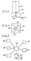
- the opto-sensor shown in FIGS. 5 and 6 has a substructure 100, which is shown here schematically as a corresponding base.
- This substructure is hollow to accommodate appropriate wiring. He has a cable version on its underside.
- the substructure is approximately square in horizontal section in this embodiment.
- a separator 200 On the base 100, a separator 200 is arranged, which has the shape of a St. Andrew's cross in horizontal section.
- the separator 200 forms four horizontally-sectioned triangular compartments 160 which are open at the top and sideways. Sunlight can thus penetrate these compartments from above and from the side.
- the two others Sides of the triangle corresponding to the subboard diagonals are occupied by the walls 600 of the separator 200, thus shielding the respective compartment from sunlight.
- a light receiving device 300 in the form of a photodiode.
- the photodiode 300 When irradiated with sunlight, the photodiode 300 generates electrical signals which are supplied via electrical conductors 400, which are combined in an electrical cable 500, a suitable control unit.
- the separation device 200 has a suitable height to allow shading of the sun relative to the vertical axis of the sensor, a shadow of the separator 200 on one or more compartments and thus arranged there the light receiving means 300.
- the exact height can be determined empirically.
- FIG. 7 shows the sensor of FIGS. 5 and 6 as part of a sun position tracking device.
- the sensor is indicated here at 800 and is located on the rotatably and pivotally arranged solar module.
- the corresponding signals of the sensor 800 are supplied to a control unit 700 (central processing unit, CPU), which also receives signals from the switches 900, 1000 of the rotary drive and rotary actuator, evaluates the received signals and outputs to the rotary actuator 110 and the rotary actuator 120 corresponding control command signals.
- the control unit 700 supplies signals to a display / operation unit 130.
- This unit has a display panel 140 and an on / off switch 150.
- the user turns on the device with the switch 150.
- the sensor 800 detects the position of the sun and supplies the control unit 700 with corresponding signals. These signals are displayed on the display panel 140. Furthermore, thereby, if necessary, corresponding command signals are generated, which are supplied to the rotary drive 110 and / or rotary actuator 120, which cause a tracking of the solar module.
- the intended limit switches 900, 1000 terminate the corresponding movements of the solar module.
Landscapes
- Engineering & Computer Science (AREA)
- Physics & Mathematics (AREA)
- General Physics & Mathematics (AREA)
- Spectroscopy & Molecular Physics (AREA)
- Life Sciences & Earth Sciences (AREA)
- Sustainable Development (AREA)
- Chemical & Material Sciences (AREA)
- Thermal Sciences (AREA)
- Sustainable Energy (AREA)
- Combustion & Propulsion (AREA)
- Mechanical Engineering (AREA)
- General Engineering & Computer Science (AREA)
- Photovoltaic Devices (AREA)
- Control Of Position Or Direction (AREA)
- Paper (AREA)
- Agricultural Chemicals And Associated Chemicals (AREA)
- Vehicle Body Suspensions (AREA)
- Soil Working Implements (AREA)
- Power-Operated Mechanisms For Wings (AREA)
Claims (14)
- Dispositif d'orientation automatique suivant la position du soleil pour un module solaire comprenant- une base (1, 2, 3) pour la fixation du dispositif à une pièce stationnaire ou mobile, en particulier un véhicule,- un élément rotatif placé de manière rotative sur la base (1, 2, 3) et entraîné par un entraînement rotatif,- un support de pivotement placé de manière pivotante vers le haut sur l'élément rotatif et entraîné par un entraînement pivotant présentant un moteur (24), sur lequel support au moins un module solaire (13) est placé, et- un capteur optique (14) qui produit des signaux en fonction de la position du soleil et les transmet à une unité de commande (10) qui ajuste l'entraînement rotatif et / ou pivotant (30),- dans lequel le support de pivotement (31) présente au moins un élément (19) relié fixement à l'élément rotatif et au moins un élément pivotant (20) placé dessus de manière pivotante, portant le module solaire (13),caractérisé en ce quel'élément rotatif est configuré comme un plateau tournant (4)le support de pivotement (31) est disposé sur le plateau tournant (4),le support de pivotement (31) présente au moins deux éléments en forme de barre ou de plaque reliés fixement au plateau tournant (4) entre lesquels ledit au moins un élément pivotant (20) est placé de manière à pivoter vers le haut, etl'entraînement pivotant (30) est placé dans la région terminale d'un des éléments (19) reliés fixement au plateau tournant (4) transversalement à son axe et l'élément (19) ne fait pas saillie vers le haut et présente un démultiplicateur (22, 23) et un arbre mené (26) d'engrenage pourvu d'une denture entre les deux éléments (19) avec lequel entre en prise une roue dentée sectorielle (25) reliée à l'élément pivotant (20) du support de pivotement (31).
- Dispositif d'orientation suivant la position du soleil selon la revendication 1, caractérisé en ce que la roue dentée sectorielle (25) couvre un arc de cercle d'environ 120°.
- Dispositif d'orientation suivant la position du soleil selon une des revendications précédentes, caractérisé en ce qu'il présente au total quatre éléments (11, 19) fixement reliés au plateau tournant (4) dont les deux extérieurs (11) sont respectivement reliés de manière pivotante à un élément pivotant (13) et les deux intérieurs (19) sont reliés à l'élément pivotant (20) présentant la roue dentée sectorielle (25).
- Dispositif d'orientation suivant la position du soleil selon une des revendications précédentes, caractérisé en ce que les éléments (11, 19) et les éléments pivotants (13, 20) fixement reliés sont des barres.
- Dispositif d'orientation suivant la position du soleil selon une des revendications précédentes, caractérisé en ce que le plateau tournant (4) est monté de manière rotative sur la base (1, 2, 3) au moyen de billes (6) disposées dans une rainure annulaire (5).
- Dispositif d'orientation suivant la position du soleil selon une des revendications précédentes, caractérisé en ce que la base (1, 2, 3) se compose d'une plaque de fond (1), d'un logement (2) disposé sur celle-ci et d'un plateau fixe (3) disposé sur celui-ci et destiné au placement du plateau rotatif (4).
- Dispositif d'orientation suivant la position du soleil selon une des revendications précédentes, caractérisé en ce que l'entraînement rotatif présente un moteur (16), un démultiplicateur (15) et une vis d'entraînement sans fin (9) qui entre en prise avec une roue dentée d'entraînement (8) pour le plateau tournant (4).
- Dispositif d'orientation suivant la position du soleil selon une des revendications précédentes, caractérisé en ce que l'entraînement rotatif et l'unité de commande (10) sont disposés dans le logement (2) de la base.
- Dispositif d'orientation suivant la position du soleil selon une des revendications précédentes, caractérisé en ce que le capteur optique (14) présenteune base (100)un dispositif séparateur (200) disposé sur la base qui divise l'espace au-dessus de la base (100) en plusieurs compartiments (160) ouverts sur le dessus et sur le côté,au moins un dispositif de réception de la lumière (300) dans chaque compartiment (160) qui convertit la lumière en courant électrique, etdes conduites électriques (400, 500) raccordées au dispositif de réception de la lumière (300) et conduisant à une unité de commande / d'évaluation / d'affichage (700).
- Dispositif d'orientation suivant la position du soleil selon la revendication 9, caractérisé en ce que le dispositif séparateur (200) divise l'espace au-dessus de la base (100) en quatre compartiments (160).
- Dispositif d'orientation suivant la position du soleil selon la revendication 9, caractérisé en ce qu'un dispositif de réception de la lumière (300) est disposé dans chaque compartiment (160).
- Dispositif d'orientation suivant la position du soleil selon une des revendications 9 à 11, caractérisé en ce que le dispositif de réception de la lumière (300) est une photodiode.
- Dispositif d'orientation suivant la position du soleil selon une des revendications 9 à 12, caractérisé en ce qu'il a une base (100) approximativement quadratique en coupe horizontale et un dispositif séparateur (200 avec des parois disposées le long des diagonales de la base (200).
- Dispositif d'orientation suivant la position du soleil selon une des revendications 9 à 13, caractérisé en ce qu'il est prévu sur un panneau solaire disposé de manière à tourner et à pivoter.
Applications Claiming Priority (1)
| Application Number | Priority Date | Filing Date | Title |
|---|---|---|---|
| PCT/DE2002/002328 WO2003102477A1 (fr) | 2002-05-28 | 2002-05-28 | Dispositif d'orientation automatique suivant la position du soleil |
Publications (2)
| Publication Number | Publication Date |
|---|---|
| EP1514060A1 EP1514060A1 (fr) | 2005-03-16 |
| EP1514060B1 true EP1514060B1 (fr) | 2007-01-24 |
Family
ID=29591693
Family Applications (1)
| Application Number | Title | Priority Date | Filing Date |
|---|---|---|---|
| EP02754271A Expired - Lifetime EP1514060B1 (fr) | 2002-05-28 | 2002-05-28 | Dispositif d'orientation automatique suivant la position du soleil |
Country Status (8)
| Country | Link |
|---|---|
| US (1) | US7202457B2 (fr) |
| EP (1) | EP1514060B1 (fr) |
| AT (1) | ATE352757T1 (fr) |
| AU (1) | AU2002320893A1 (fr) |
| CA (1) | CA2526993A1 (fr) |
| DE (2) | DE50209395D1 (fr) |
| ES (1) | ES2281533T3 (fr) |
| WO (1) | WO2003102477A1 (fr) |
Cited By (2)
| Publication number | Priority date | Publication date | Assignee | Title |
|---|---|---|---|---|
| DE102009013752A1 (de) * | 2009-03-17 | 2010-10-07 | Christian Singe | Photovoltaische Vorrichtung |
| CN102562501A (zh) * | 2010-12-07 | 2012-07-11 | 张建城 | 槽式太阳能热发电聚光阵列集群管理控制装置 |
Families Citing this family (66)
| Publication number | Priority date | Publication date | Assignee | Title |
|---|---|---|---|---|
| US7464703B2 (en) * | 2005-08-18 | 2008-12-16 | Jack Aaron | Sun tracker for solar panels |
| WO2007039246A2 (fr) * | 2005-10-01 | 2007-04-12 | Nikolaus Johannes Laing | Generateur de courant de solaire basculant |
| EP1791184A1 (fr) * | 2005-11-29 | 2007-05-30 | Dr. H. Frauenknecht GmbH | Installation solaire et son procédé d'exploitation |
| US20070243820A1 (en) | 2006-04-18 | 2007-10-18 | O'hagin Carolina | Automatic roof ventilation system |
| US7476832B2 (en) | 2006-06-29 | 2009-01-13 | Herb Vendig | Seasonally adjustable mounting system for solar panels having dual motor assembly |
| US7875796B2 (en) * | 2006-07-28 | 2011-01-25 | Megawatt Solar, Inc. | Reflector assemblies, systems, and methods for collecting solar radiation for photovoltaic electricity generation |
| GB2442982A (en) * | 2006-10-16 | 2008-04-23 | Peter William Richards | A solar tracking device |
| US8180491B2 (en) * | 2007-03-02 | 2012-05-15 | Solar Revolution Llc | Systems and methods for solar affected environmental control |
| WO2008147560A1 (fr) * | 2007-05-24 | 2008-12-04 | Megawatt Solar, Inc. | Systèmes de collecte photovoltaïques, entraînements par frottement et procédé pour suivre le soleil et éviter un endommagement par le vent |
| ES2343395B1 (es) * | 2007-08-17 | 2011-06-20 | Industrias Mecanicas De Tudela, S.A | Seguidor solar para equipos productores de energia. |
| WO2009048879A2 (fr) * | 2007-10-12 | 2009-04-16 | Megawatt Solar, Inc. | Procédés, systèmes et supports lisibles par ordinateur permettant de commander l'orientation d'un système de collecte photovoltaïque pour suivre le mouvement apparent du soleil |
| US8350204B2 (en) | 2007-12-12 | 2013-01-08 | Mark Moser | Light source tracker |
| EP2232201B1 (fr) * | 2007-12-12 | 2017-05-10 | Mark K. Moser | Dispositif de suivi de source de lumière |
| US20100330898A1 (en) * | 2008-02-26 | 2010-12-30 | Daniels Gregory S | Roof ventilation system |
| US20100139645A1 (en) * | 2008-12-01 | 2010-06-10 | Sun-A-Ray, Llc. | Balanced support and solar tracking system for panels of photovoltaic cells |
| US8492645B1 (en) | 2009-04-22 | 2013-07-23 | Michael Strahm | Transportable solar power system |
| KR101002856B1 (ko) * | 2009-06-03 | 2010-12-21 | 주식회사 그린플러스 | 지붕설치형 양방향 태양광 추적 집광장치 |
| FR2949549A1 (fr) * | 2009-09-02 | 2011-03-04 | Rodolphe Collilieux | Base tournante ou suiveur pour tous types de panneaux solaires autonomes a fortes charges |
| US8490619B2 (en) | 2009-11-20 | 2013-07-23 | International Business Machines Corporation | Solar energy alignment and collection system |
| EP2504863B1 (fr) | 2009-11-24 | 2021-01-13 | Guy Pizzarello | Systèmes de suivi solaire à profil bas et procédés associés |
| US9127859B2 (en) * | 2010-01-13 | 2015-09-08 | International Business Machines Corporation | Multi-point cooling system for a solar concentrator |
| KR100961982B1 (ko) | 2010-03-03 | 2010-06-08 | 주식회사 한국리레이 | 태양발전기용 태양전지판 구동 장치 |
| KR100961984B1 (ko) | 2010-03-03 | 2010-06-08 | 주식회사 한국리레이 | 안전 기능을 갖는 태양전지판 구동 장치 |
| CN101847951A (zh) * | 2010-03-04 | 2010-09-29 | 张晋 | 单点俯角跟踪多点同步支撑太阳能电站 |
| CN101783623B (zh) * | 2010-03-17 | 2012-08-08 | 北京印刷学院 | 长行程液压杆传动同步支撑采光太阳能电站 |
| CN101847952B (zh) * | 2010-05-25 | 2012-08-08 | 张晋 | 大功率齿条驱动俯角跟踪三维太阳能采光装置 |
| US8701800B2 (en) * | 2010-08-18 | 2014-04-22 | Monarch Power Corp | Solar electric vehicle with foldable body panels on a sun tracking chassis |
| CN102005974B (zh) * | 2010-11-03 | 2013-07-31 | 佛山市山日汽车电动轮毂有限公司 | 一种太阳能设备的追日回转装置 |
| CN102486652A (zh) * | 2010-12-02 | 2012-06-06 | 株式会社格林普乐斯 | 壁装型的追踪和聚集阳光的设备 |
| CN102487254A (zh) * | 2010-12-06 | 2012-06-06 | 西安大昱光电科技有限公司 | 跟踪器时控驱动控制系统 |
| CN102541081B (zh) * | 2010-12-10 | 2014-12-17 | 比亚迪股份有限公司 | 太阳能跟踪光电传感器以及光伏发电系统 |
| CN102064743B (zh) * | 2011-02-01 | 2013-05-15 | 河海大学常州校区 | 碟式太阳能跟踪与方向角驱动系统 |
| WO2012117123A1 (fr) * | 2011-03-03 | 2012-09-07 | Aplicaciones Renovables Integradas, S.L. | Héliostat comprenant un axe d'actionnement visant une cible, capteur de réflexion et commande en boucle fermée |
| RU2488046C2 (ru) * | 2011-08-02 | 2013-07-20 | Российская Федерация, От Имени Которой Выступает Министерство Промышленности И Торговли Российской Федерации | Система слежения за солнцем фотоэнергоустановки |
| US8895836B2 (en) | 2011-10-19 | 2014-11-25 | King Saud University | Dual axis solar tracker apparatus and method |
| CN102541076A (zh) * | 2011-12-16 | 2012-07-04 | 曾宪来 | 太阳追踪器 |
| CN103151962A (zh) * | 2013-03-22 | 2013-06-12 | 哈尔滨工业大学 | 一种具有追光传感器的太阳能发电装置 |
| CN103414381A (zh) * | 2013-06-09 | 2013-11-27 | 太仓苏晟电气技术科技有限公司 | 一种太阳能发电系统及其使用方法 |
| US9394693B2 (en) | 2013-11-22 | 2016-07-19 | Gregory S. Daniels | Roof vent for supporting a solar panel |
| AU2014385207B2 (en) | 2014-03-06 | 2019-11-28 | Gregory S. Daniels | Roof vent with an integrated fan |
| USD755944S1 (en) | 2014-03-06 | 2016-05-10 | Gregory S. Daniels | Roof vent assembly |
| USD748239S1 (en) | 2014-03-06 | 2016-01-26 | Gregory S. Daniels | Roof vent assembly |
| US9732987B2 (en) | 2014-06-06 | 2017-08-15 | King Saud University | Two axis solar tracking system |
| TWI572834B (zh) | 2014-09-10 | 2017-03-01 | 第一傳動科技股份有限公司 | 太陽能追日設備的轉向裝置 |
| CN105203207B (zh) * | 2015-10-29 | 2017-05-24 | 沈阳师范大学 | 一种原料晾晒用跟踪日照弹簧拉力装置 |
| USD891604S1 (en) | 2015-11-19 | 2020-07-28 | Gregory S. Daniels | Roof vent assembly |
| US11326793B2 (en) | 2018-12-21 | 2022-05-10 | Gregory S. Daniels | Roof vent and roof ventilation system |
| USD930810S1 (en) | 2015-11-19 | 2021-09-14 | Gregory S. Daniels | Roof vent |
| US10903789B2 (en) | 2016-05-09 | 2021-01-26 | Nova Lumos Ltd. | System and method for optimizing energy generation |
| US10720675B2 (en) | 2016-06-07 | 2020-07-21 | Nova Lumos Ltd. | System and method for prolonging battery life |
| CN106301182A (zh) * | 2016-08-27 | 2017-01-04 | 无锡中洁能源技术有限公司 | 一种转动式太阳能电池板 |
| CN106208935A (zh) * | 2016-08-27 | 2016-12-07 | 无锡中洁能源技术有限公司 | 一种双转动太阳能电池板 |
| CN106655997A (zh) * | 2016-08-27 | 2017-05-10 | 无锡中洁能源技术有限公司 | 一种自动转动太阳能电池板 |
| DE102017112608A1 (de) * | 2017-06-08 | 2018-12-13 | Innogy Se | Photovoltaikvorrichtung für Container |
| US20190105991A1 (en) * | 2017-10-11 | 2019-04-11 | Divergent Technologies, Inc. | Solar extended range electric vehicle |
| CN108870773A (zh) * | 2018-06-22 | 2018-11-23 | 安徽志成机械科技有限公司 | 一种可旋转的太阳能板 |
| CN110492833A (zh) * | 2018-08-10 | 2019-11-22 | 合肥甘来新材料有限公司 | 一种可变动角度的太阳能板装置 |
| US11711049B2 (en) * | 2019-04-02 | 2023-07-25 | JBC Technologies, LLC | Solar tracking system for a recreational vehicle |
| CN110286696A (zh) * | 2019-08-06 | 2019-09-27 | 沈阳信元瑞科技有限公司 | 双维追日控制系统 |
| WO2022027276A1 (fr) * | 2020-08-05 | 2022-02-10 | 李�杰 | Système de suivi de production d'énergie photovoltaïque monté sur véhicule sans capteur photoélectrique |
| USD963834S1 (en) | 2020-10-27 | 2022-09-13 | Gregory S. Daniels | Roof vent with a circular integrated fan |
| USD964546S1 (en) | 2020-10-27 | 2022-09-20 | Gregory S. Daniels | Roof vent with a circular integrated fan |
| RU2758783C1 (ru) * | 2021-04-15 | 2021-11-01 | федеральное государственное бюджетное образовательное учреждение высшего образования «Санкт-Петербургский горный университет» | Устройство для исследования систем слежения за солнцем |
| CN115195488A (zh) * | 2022-07-21 | 2022-10-18 | 厦门冠宇科技股份有限公司 | 一种车载太阳能充电装置 |
| UA156589U (uk) * | 2022-11-28 | 2024-07-17 | Максим Євгенович Костяний | Автоматична система позиціонування фотоелектричних панелей |
| KR102710658B1 (ko) * | 2023-12-28 | 2024-09-27 | 청봉산업 주식회사 | 태양광 추적식 영농형 태양광 시스템 |
Family Cites Families (17)
| Publication number | Priority date | Publication date | Assignee | Title |
|---|---|---|---|---|
| US3131069A (en) * | 1960-12-28 | 1964-04-28 | Oscar Mayer & Company Inc | Package of materials which are subject to undesirable deterioration |
| US3354613A (en) * | 1965-04-28 | 1967-11-28 | Mahaffy & Harder Eng Co | Packaging apparatus with improved product loader |
| US3410698A (en) * | 1967-02-07 | 1968-11-12 | Armour & Co | Product container |
| US3937389A (en) * | 1971-12-27 | 1976-02-10 | Harold Wind | Disposable food container |
| DE2963659D1 (en) * | 1978-03-23 | 1982-11-04 | Alastair Robertson | Solar energy converters |
| US4195905A (en) * | 1978-03-23 | 1980-04-01 | Hansen Paul A | Automatic biaxial sun tracking mechanism for solar energy utilization devices |
| DE3047724A1 (de) * | 1980-12-18 | 1982-07-15 | Fa. Paul Weiß, 8500 Nürnberg | Nachfuehrvorrichtung zur sonnenstandabhaengigen ausrichtung von sonnenenergiesammlern |
| FR2557540B1 (fr) * | 1983-12-30 | 1986-09-19 | Guiffray Michel | Procede de fabrication de recipients en matiere souple ou semi-rigide et a goulot allonge et recipients fabriques par ce procede |
| NZ209770A (en) * | 1984-10-04 | 1988-07-28 | Trigon Packaging Systems | Open tray with stepped cavities and surrounding flange |
| AU597299B3 (en) * | 1989-07-12 | 1990-06-21 | Christian Studer | A mechanical construction for a solar tracking system |
| US5191875A (en) * | 1991-09-27 | 1993-03-09 | Edling Jack V | High efficiency solar boiler |
| WO1995000806A1 (fr) * | 1993-06-17 | 1995-01-05 | Devappa | Dispositif permettant de produire de l'energie electrique a partir de l'energie solaire |
| DE19928857C2 (de) * | 1999-06-24 | 2001-06-07 | Otto Lieber | Zweiachsig nachführbare Solarzellenanordnung |
| FR2798718B1 (fr) * | 1999-09-17 | 2001-11-23 | Alden Loisirs Et Tech | Dispositif de support et de positionnement controle pour un element sensiblement en forme de panneau |
| US6443145B1 (en) * | 2000-08-25 | 2002-09-03 | Learning Legacy | Solar seeker |
| DE10059721A1 (de) * | 2000-11-30 | 2002-06-13 | Berger Solar Berger & Kroeter | Selbsttätig wirkende Sonnenstandsnachführeinrichtung |
| JP2002299673A (ja) * | 2001-03-29 | 2002-10-11 | Ikuji Sasaki | 太陽光を利用した発電装置 |
-
2002
- 2002-05-28 US US10/516,653 patent/US7202457B2/en not_active Expired - Lifetime
- 2002-05-28 AU AU2002320893A patent/AU2002320893A1/en not_active Abandoned
- 2002-05-28 DE DE50209395T patent/DE50209395D1/de not_active Expired - Lifetime
- 2002-05-28 DE DE10297779T patent/DE10297779D2/de not_active Expired - Fee Related
- 2002-05-28 ES ES02754271T patent/ES2281533T3/es not_active Expired - Lifetime
- 2002-05-28 WO PCT/DE2002/002328 patent/WO2003102477A1/fr not_active Ceased
- 2002-05-28 EP EP02754271A patent/EP1514060B1/fr not_active Expired - Lifetime
- 2002-05-28 CA CA002526993A patent/CA2526993A1/fr not_active Abandoned
- 2002-05-28 AT AT02754271T patent/ATE352757T1/de not_active IP Right Cessation
Cited By (4)
| Publication number | Priority date | Publication date | Assignee | Title |
|---|---|---|---|---|
| DE102009013752A1 (de) * | 2009-03-17 | 2010-10-07 | Christian Singe | Photovoltaische Vorrichtung |
| DE102009013752B4 (de) * | 2009-03-17 | 2017-07-06 | Christian Singe | Photovoltaische Vorrichtung |
| CN102562501A (zh) * | 2010-12-07 | 2012-07-11 | 张建城 | 槽式太阳能热发电聚光阵列集群管理控制装置 |
| CN102562501B (zh) * | 2010-12-07 | 2014-07-02 | 张建城 | 槽式太阳能热发电聚光阵列集群管理控制装置 |
Also Published As
| Publication number | Publication date |
|---|---|
| US20060124827A1 (en) | 2006-06-15 |
| ATE352757T1 (de) | 2007-02-15 |
| CA2526993A1 (fr) | 2003-12-11 |
| EP1514060A1 (fr) | 2005-03-16 |
| WO2003102477A1 (fr) | 2003-12-11 |
| DE10297779D2 (de) | 2005-04-28 |
| ES2281533T3 (es) | 2007-10-01 |
| DE50209395D1 (de) | 2007-03-15 |
| US7202457B2 (en) | 2007-04-10 |
| AU2002320893A1 (en) | 2003-12-19 |
Similar Documents
| Publication | Publication Date | Title |
|---|---|---|
| EP1514060B1 (fr) | Dispositif d'orientation automatique suivant la position du soleil | |
| EP1649212B1 (fr) | Dispositif d'eclairage de locaux | |
| AT517705B1 (de) | Schwenk- und Fächerantrieb für Solarpaneele | |
| DE212023000026U1 (de) | Solare Straßenbeleuchtung zur einfachen Einstellung des Winkels des Solarpanels | |
| WO2001090662A2 (fr) | Systeme d'energie solaire concentrateur | |
| DE2515154A1 (de) | Zelt | |
| DE10059721A1 (de) | Selbsttätig wirkende Sonnenstandsnachführeinrichtung | |
| DE202009017658U1 (de) | Vorrichtung, insbesondere Heliostat oder Photovoltaikeinrichtung | |
| EP1500870A1 (fr) | Lampe alimentée à l'énergie solaire | |
| EP1788322A1 (fr) | Monture pour un groupe de modules solaires | |
| DE212023000014U1 (de) | Solarstraßenlaterne | |
| DE3136854C2 (de) | Hebedach | |
| DE19907332C1 (de) | Fahrzeugdach mit mehreren Solarzelleneinheiten | |
| DE102006010781A1 (de) | Sonnenstandsnachführeinrichtung für ein Solarmodul | |
| DE102005051722A1 (de) | Schwenkantrieb für ein Drehtor | |
| DE202024105605U1 (de) | Drehbarer und faltbarer Halter für Sonnenkollektoren | |
| EP3631288B1 (fr) | Module d'éclairage à del pour un phare de véhicule à moteur | |
| DE102009022876A1 (de) | Nachführeinheit sowie Sonnenkollektor- oder Photovoltaikeinheit | |
| DE10059723A1 (de) | Sensor zur Erfassung des Sonnenstandes | |
| WO2023180154A1 (fr) | Appareil d'ombrage temporaire de systèmes de feux de circulation | |
| DE202004008911U1 (de) | Photovoltaikanlage, welche von einer auf die gegenüberliegende Dachseite nachgeführt wird | |
| DE102004037722B4 (de) | Antriebs- und Befestigungsvorrichtung für einen dem Sonnenverlauf folgenden Sonnenkollektor | |
| DE7924579U1 (de) | Halterung fuer sonnenkollektoren | |
| CN221778714U (zh) | 一种绿色建筑墙体结构 | |
| CN114120680B (zh) | 一种防落叶的新能源led交通信号灯 |
Legal Events
| Date | Code | Title | Description |
|---|---|---|---|
| PUAI | Public reference made under article 153(3) epc to a published international application that has entered the european phase |
Free format text: ORIGINAL CODE: 0009012 |
|
| 17P | Request for examination filed |
Effective date: 20041223 |
|
| AK | Designated contracting states |
Kind code of ref document: A1 Designated state(s): AT BE CH CY DE DK ES FI FR GB GR IE IT LI LU MC NL PT SE TR |
|
| AX | Request for extension of the european patent |
Extension state: AL LT LV MK RO SI |
|
| 17Q | First examination report despatched |
Effective date: 20050509 |
|
| DAX | Request for extension of the european patent (deleted) | ||
| GRAP | Despatch of communication of intention to grant a patent |
Free format text: ORIGINAL CODE: EPIDOSNIGR1 |
|
| GRAS | Grant fee paid |
Free format text: ORIGINAL CODE: EPIDOSNIGR3 |
|
| RAP1 | Party data changed (applicant data changed or rights of an application transferred) |
Owner name: FENGLER, GISELHER |
|
| GRAA | (expected) grant |
Free format text: ORIGINAL CODE: 0009210 |
|
| AK | Designated contracting states |
Kind code of ref document: B1 Designated state(s): AT BE CH CY DE DK ES FI FR GB GR IE IT LI LU MC NL PT SE TR |
|
| PG25 | Lapsed in a contracting state [announced via postgrant information from national office to epo] |
Ref country code: NL Free format text: LAPSE BECAUSE OF FAILURE TO SUBMIT A TRANSLATION OF THE DESCRIPTION OR TO PAY THE FEE WITHIN THE PRESCRIBED TIME-LIMIT Effective date: 20070124 Ref country code: FI Free format text: LAPSE BECAUSE OF FAILURE TO SUBMIT A TRANSLATION OF THE DESCRIPTION OR TO PAY THE FEE WITHIN THE PRESCRIBED TIME-LIMIT Effective date: 20070124 Ref country code: IE Free format text: LAPSE BECAUSE OF FAILURE TO SUBMIT A TRANSLATION OF THE DESCRIPTION OR TO PAY THE FEE WITHIN THE PRESCRIBED TIME-LIMIT Effective date: 20070124 Ref country code: DK Free format text: LAPSE BECAUSE OF FAILURE TO SUBMIT A TRANSLATION OF THE DESCRIPTION OR TO PAY THE FEE WITHIN THE PRESCRIBED TIME-LIMIT Effective date: 20070124 |
|
| REG | Reference to a national code |
Ref country code: GB Ref legal event code: FG4D Free format text: NOT ENGLISH |
|
| REG | Reference to a national code |
Ref country code: CH Ref legal event code: EP |
|
| REG | Reference to a national code |
Ref country code: IE Ref legal event code: FG4D Free format text: LANGUAGE OF EP DOCUMENT: GERMAN |
|
| REF | Corresponds to: |
Ref document number: 50209395 Country of ref document: DE Date of ref document: 20070315 Kind code of ref document: P |
|
| REG | Reference to a national code |
Ref country code: SE Ref legal event code: TRGR |
|
| GBT | Gb: translation of ep patent filed (gb section 77(6)(a)/1977) |
Effective date: 20070426 |
|
| PG25 | Lapsed in a contracting state [announced via postgrant information from national office to epo] |
Ref country code: PT Free format text: LAPSE BECAUSE OF FAILURE TO SUBMIT A TRANSLATION OF THE DESCRIPTION OR TO PAY THE FEE WITHIN THE PRESCRIBED TIME-LIMIT Effective date: 20070625 |
|
| NLV1 | Nl: lapsed or annulled due to failure to fulfill the requirements of art. 29p and 29m of the patents act | ||
| ET | Fr: translation filed | ||
| REG | Reference to a national code |
Ref country code: IE Ref legal event code: FD4D |
|
| REG | Reference to a national code |
Ref country code: ES Ref legal event code: FG2A Ref document number: 2281533 Country of ref document: ES Kind code of ref document: T3 |
|
| PLBE | No opposition filed within time limit |
Free format text: ORIGINAL CODE: 0009261 |
|
| STAA | Information on the status of an ep patent application or granted ep patent |
Free format text: STATUS: NO OPPOSITION FILED WITHIN TIME LIMIT |
|
| BERE | Be: lapsed |
Owner name: FENGLER, GISELHER Effective date: 20070531 |
|
| 26N | No opposition filed |
Effective date: 20071025 |
|
| REG | Reference to a national code |
Ref country code: CH Ref legal event code: PL |
|
| PG25 | Lapsed in a contracting state [announced via postgrant information from national office to epo] |
Ref country code: MC Free format text: LAPSE BECAUSE OF NON-PAYMENT OF DUE FEES Effective date: 20070531 |
|
| PG25 | Lapsed in a contracting state [announced via postgrant information from national office to epo] |
Ref country code: CH Free format text: LAPSE BECAUSE OF NON-PAYMENT OF DUE FEES Effective date: 20070531 Ref country code: LI Free format text: LAPSE BECAUSE OF NON-PAYMENT OF DUE FEES Effective date: 20070531 |
|
| PG25 | Lapsed in a contracting state [announced via postgrant information from national office to epo] |
Ref country code: BE Free format text: LAPSE BECAUSE OF NON-PAYMENT OF DUE FEES Effective date: 20070531 |
|
| PG25 | Lapsed in a contracting state [announced via postgrant information from national office to epo] |
Ref country code: GR Free format text: LAPSE BECAUSE OF FAILURE TO SUBMIT A TRANSLATION OF THE DESCRIPTION OR TO PAY THE FEE WITHIN THE PRESCRIBED TIME-LIMIT Effective date: 20070425 |
|
| PG25 | Lapsed in a contracting state [announced via postgrant information from national office to epo] |
Ref country code: AT Free format text: LAPSE BECAUSE OF NON-PAYMENT OF DUE FEES Effective date: 20070528 |
|
| PG25 | Lapsed in a contracting state [announced via postgrant information from national office to epo] |
Ref country code: CY Free format text: LAPSE BECAUSE OF FAILURE TO SUBMIT A TRANSLATION OF THE DESCRIPTION OR TO PAY THE FEE WITHIN THE PRESCRIBED TIME-LIMIT Effective date: 20070124 |
|
| PG25 | Lapsed in a contracting state [announced via postgrant information from national office to epo] |
Ref country code: LU Free format text: LAPSE BECAUSE OF NON-PAYMENT OF DUE FEES Effective date: 20070528 |
|
| PG25 | Lapsed in a contracting state [announced via postgrant information from national office to epo] |
Ref country code: TR Free format text: LAPSE BECAUSE OF FAILURE TO SUBMIT A TRANSLATION OF THE DESCRIPTION OR TO PAY THE FEE WITHIN THE PRESCRIBED TIME-LIMIT Effective date: 20070124 |
|
| PGFP | Annual fee paid to national office [announced via postgrant information from national office to epo] |
Ref country code: FR Payment date: 20101210 Year of fee payment: 9 |
|
| PGFP | Annual fee paid to national office [announced via postgrant information from national office to epo] |
Ref country code: IT Payment date: 20101130 Year of fee payment: 9 Ref country code: SE Payment date: 20101129 Year of fee payment: 9 Ref country code: GB Payment date: 20101126 Year of fee payment: 9 |
|
| PGFP | Annual fee paid to national office [announced via postgrant information from national office to epo] |
Ref country code: ES Payment date: 20101130 Year of fee payment: 9 |
|
| REG | Reference to a national code |
Ref country code: SE Ref legal event code: EUG |
|
| GBPC | Gb: european patent ceased through non-payment of renewal fee |
Effective date: 20110528 |
|
| REG | Reference to a national code |
Ref country code: FR Ref legal event code: ST Effective date: 20120131 |
|
| PG25 | Lapsed in a contracting state [announced via postgrant information from national office to epo] |
Ref country code: IT Free format text: LAPSE BECAUSE OF NON-PAYMENT OF DUE FEES Effective date: 20110528 |
|
| REG | Reference to a national code |
Ref country code: DE Ref legal event code: R119 Ref document number: 50209395 Country of ref document: DE Effective date: 20111201 |
|
| PG25 | Lapsed in a contracting state [announced via postgrant information from national office to epo] |
Ref country code: FR Free format text: LAPSE BECAUSE OF NON-PAYMENT OF DUE FEES Effective date: 20110531 |
|
| REG | Reference to a national code |
Ref country code: DE Ref legal event code: R073 Ref document number: 50209395 Country of ref document: DE |
|
| PG25 | Lapsed in a contracting state [announced via postgrant information from national office to epo] |
Ref country code: GB Free format text: LAPSE BECAUSE OF NON-PAYMENT OF DUE FEES Effective date: 20110528 |
|
| REG | Reference to a national code |
Ref country code: ES Ref legal event code: FD2A Effective date: 20120717 |
|
| PG25 | Lapsed in a contracting state [announced via postgrant information from national office to epo] |
Ref country code: ES Free format text: LAPSE BECAUSE OF NON-PAYMENT OF DUE FEES Effective date: 20110529 |
|
| REG | Reference to a national code |
Ref country code: DE Ref legal event code: R074 Ref document number: 50209395 Country of ref document: DE Effective date: 20120609 |
|
| PG25 | Lapsed in a contracting state [announced via postgrant information from national office to epo] |
Ref country code: SE Free format text: LAPSE BECAUSE OF NON-PAYMENT OF DUE FEES Effective date: 20110529 |
|
| REG | Reference to a national code |
Ref country code: DE Ref legal event code: R082 Ref document number: 50209395 Country of ref document: DE |
|
| REG | Reference to a national code |
Ref country code: DE Ref legal event code: R079 Ref document number: 50209395 Country of ref document: DE Free format text: PREVIOUS MAIN CLASS: F24J0002380000 Ipc: F24S0050200000 |
|
| PGFP | Annual fee paid to national office [announced via postgrant information from national office to epo] |
Ref country code: DE Payment date: 20181122 Year of fee payment: 17 |
|
| REG | Reference to a national code |
Ref country code: DE Ref legal event code: R119 Ref document number: 50209395 Country of ref document: DE |
|
| PG25 | Lapsed in a contracting state [announced via postgrant information from national office to epo] |
Ref country code: DE Free format text: LAPSE BECAUSE OF NON-PAYMENT OF DUE FEES Effective date: 20191203 |