EP1500829B1 - Dispositif à vis pour l'assemblage de deux pièces - Google Patents
Dispositif à vis pour l'assemblage de deux pièces Download PDFInfo
- Publication number
- EP1500829B1 EP1500829B1 EP04009585A EP04009585A EP1500829B1 EP 1500829 B1 EP1500829 B1 EP 1500829B1 EP 04009585 A EP04009585 A EP 04009585A EP 04009585 A EP04009585 A EP 04009585A EP 1500829 B1 EP1500829 B1 EP 1500829B1
- Authority
- EP
- European Patent Office
- Prior art keywords
- assembly
- blind rivet
- screw
- helix
- base member
- Prior art date
- Legal status (The legal status is an assumption and is not a legal conclusion. Google has not performed a legal analysis and makes no representation as to the accuracy of the status listed.)
- Expired - Lifetime
Links
- 239000004033 plastic Substances 0.000 claims description 12
- 239000000463 material Substances 0.000 claims description 8
- 238000007789 sealing Methods 0.000 claims description 5
- 239000004952 Polyamide Substances 0.000 claims description 2
- 238000003780 insertion Methods 0.000 claims description 2
- 230000037431 insertion Effects 0.000 claims description 2
- 229920002647 polyamide Polymers 0.000 claims description 2
- 239000002184 metal Substances 0.000 claims 1
- 238000004519 manufacturing process Methods 0.000 description 6
- 239000011324 bead Substances 0.000 description 4
- 238000000034 method Methods 0.000 description 4
- 230000033001 locomotion Effects 0.000 description 3
- 239000000243 solution Substances 0.000 description 3
- 230000010006 flight Effects 0.000 description 2
- 238000010079 rubber tapping Methods 0.000 description 2
- 230000007704 transition Effects 0.000 description 2
- 229910000831 Steel Inorganic materials 0.000 description 1
- 230000001419 dependent effect Effects 0.000 description 1
- 238000002347 injection Methods 0.000 description 1
- 239000007924 injection Substances 0.000 description 1
- 238000001746 injection moulding Methods 0.000 description 1
- 238000009434 installation Methods 0.000 description 1
- 230000002093 peripheral effect Effects 0.000 description 1
- 238000004064 recycling Methods 0.000 description 1
- 239000010959 steel Substances 0.000 description 1
Images

Classifications
-
- F—MECHANICAL ENGINEERING; LIGHTING; HEATING; WEAPONS; BLASTING
- F16—ENGINEERING ELEMENTS AND UNITS; GENERAL MEASURES FOR PRODUCING AND MAINTAINING EFFECTIVE FUNCTIONING OF MACHINES OR INSTALLATIONS; THERMAL INSULATION IN GENERAL
- F16B—DEVICES FOR FASTENING OR SECURING CONSTRUCTIONAL ELEMENTS OR MACHINE PARTS TOGETHER, e.g. NAILS, BOLTS, CIRCLIPS, CLAMPS, CLIPS OR WEDGES; JOINTS OR JOINTING
- F16B5/00—Joining sheets or plates, e.g. panels, to one another or to strips or bars parallel to them
- F16B5/02—Joining sheets or plates, e.g. panels, to one another or to strips or bars parallel to them by means of fastening members using screw-thread
- F16B5/0258—Joining sheets or plates, e.g. panels, to one another or to strips or bars parallel to them by means of fastening members using screw-thread using resiliently deformable sleeves, grommets or inserts
-
- F—MECHANICAL ENGINEERING; LIGHTING; HEATING; WEAPONS; BLASTING
- F16—ENGINEERING ELEMENTS AND UNITS; GENERAL MEASURES FOR PRODUCING AND MAINTAINING EFFECTIVE FUNCTIONING OF MACHINES OR INSTALLATIONS; THERMAL INSULATION IN GENERAL
- F16B—DEVICES FOR FASTENING OR SECURING CONSTRUCTIONAL ELEMENTS OR MACHINE PARTS TOGETHER, e.g. NAILS, BOLTS, CIRCLIPS, CLAMPS, CLIPS OR WEDGES; JOINTS OR JOINTING
- F16B13/00—Dowels or other devices fastened in walls or the like by inserting them in holes made therein for that purpose
- F16B13/02—Dowels or other devices fastened in walls or the like by inserting them in holes made therein for that purpose in one piece with protrusions or ridges on the shaft
-
- F—MECHANICAL ENGINEERING; LIGHTING; HEATING; WEAPONS; BLASTING
- F16—ENGINEERING ELEMENTS AND UNITS; GENERAL MEASURES FOR PRODUCING AND MAINTAINING EFFECTIVE FUNCTIONING OF MACHINES OR INSTALLATIONS; THERMAL INSULATION IN GENERAL
- F16B—DEVICES FOR FASTENING OR SECURING CONSTRUCTIONAL ELEMENTS OR MACHINE PARTS TOGETHER, e.g. NAILS, BOLTS, CIRCLIPS, CLAMPS, CLIPS OR WEDGES; JOINTS OR JOINTING
- F16B13/00—Dowels or other devices fastened in walls or the like by inserting them in holes made therein for that purpose
- F16B13/12—Separate metal or non-separate or non-metal dowel sleeves fastened by inserting the screw, nail or the like
- F16B13/124—Separate metal or non-separate or non-metal dowel sleeves fastened by inserting the screw, nail or the like fastened by inserting a threaded element, e.g. screw or bolt
-
- F—MECHANICAL ENGINEERING; LIGHTING; HEATING; WEAPONS; BLASTING
- F16—ENGINEERING ELEMENTS AND UNITS; GENERAL MEASURES FOR PRODUCING AND MAINTAINING EFFECTIVE FUNCTIONING OF MACHINES OR INSTALLATIONS; THERMAL INSULATION IN GENERAL
- F16B—DEVICES FOR FASTENING OR SECURING CONSTRUCTIONAL ELEMENTS OR MACHINE PARTS TOGETHER, e.g. NAILS, BOLTS, CIRCLIPS, CLAMPS, CLIPS OR WEDGES; JOINTS OR JOINTING
- F16B19/00—Bolts without screw-thread; Pins, including deformable elements; Rivets
- F16B19/04—Rivets; Spigots or the like fastened by riveting
- F16B19/08—Hollow rivets; Multi-part rivets
- F16B19/10—Hollow rivets; Multi-part rivets fastened by expanding mechanically
- F16B19/1027—Multi-part rivets
- F16B19/1036—Blind rivets
- F16B19/1081—Blind rivets fastened by a drive-pin
Definitions
- the present invention relates to an arrangement of two components and a screw connection for connecting the two components according to the preamble of claim 1 and a blind rivet for this purpose.
- a certain disadvantage of this ertellsan eleven is that the nut-like blind rivet has an undercut due to the shoulder-shaped stepped transition point, which makes the production of the blind rivet difficult. If the blind rivet is injection-molded from plastic, a separable jaw tool for forming the blind rivet is required due to the undercut. The result is that only a relatively limited number of blind rivets can be made simultaneously (Limited nest design) and a correspondingly long demolding time is required. To achieve sufficient strength of the threaded connection assembly, relatively large dimensions of the parts may be required.
- An arrangement according to the preamble of claim 1 is known from FR-A-1 406 174 or from DE-A-2 818 588.
- the ribs have the form of axially extending projections of different shape.
- the present invention has for its object to provide an assembly of two components and a screw connection for connecting the two components and a blind rivet for this arrangement, which ensures a functionally reliable, heavy-duty and durable connection of the two components with ease of manufacture and comparatively small dimensions.
- the attachment hole of one of the two components is designed as polygonal, preferably as a square.
- the blind rivet has a cylindrical base body, which is provided on its outer side with a multi-start, preferably administrat versen, helix, wherein the number of helical turns is equal to the number of corners of the polygonal mounting hole. Further, the dimensions of the helix and the dimensions of the polygonal mounting hole are coordinated so that in the assembled state, the helical turns largely fill the corners of the polygonal mounting hole. This creates an anti-rotation between the blind rivet and the associated component.
- the "rivet bead" of the blind rivet is thus formed by the helix. Because the folding zone is radially outward compared to the prior art, can be achieved in the inventively designed ermorsanowskiowskiowski the same strength as in the prior art with smaller dimensions of the screw and the blind rivet including the mounting holes. Moreover, since the present invention formed blind rivet has no undercut, simplifies its production. Thus, a simple plate tool can be used in injection molding of the plastic blind rivet. To remove the blind rivet from the plate tool, a linear ejector movement is sufficient in which the helix independently revolves out of the plate tool in a rotating manner.
- the helix has the shape of a pointed thread and a pitch angle greater than its self-locking angle.
- the blind rivet is therefore pressed in the assembly in the polygonal mounting hole of the relevant component in the axial direction, wherein performs a rotating movement by the large helical pitch of the blind rivet. If the component has a sufficient thickness, then, as a result of the helical course of the helix, a clamping arrangement acting as a captive securing device arises between the helix and the polygonal mounting hole. With a relatively small wall thickness of the relevant component, it is advisable to provide nubs on the outside of the main body of the blind rivet as additional captive protection.
- the base body of the blind rivet is provided at its one end with a flange which has on one side a sealing lip which is pressed in the manufacture of the screw in sealing engagement with the associated component. If the main body of the blind rivet is closed at its other end by a bottom, so creates a watertight screw connection.
- Both the blind rivet and the screw can be made of plastic.
- the result is a "pure" all-plastic solution, which is particularly advantageous in terms of manufacturing costs, weight and recycling.
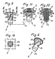
- the screw connection arrangement shown in the assembled state in FIGS. 11 and 12 serves for connecting two plate-shaped components 2, 4, which are accessible only from one side, in the drawing only from the top side.
- the component 2 is the body panel and the component 4 is the wheel housing shell for a motor vehicle. It is understood, however, that the invention is not limited thereto.
- the screw connection arrangement consists of a screw 6, which is shown in Figure 1 as a single part, and a nut-like blind rivet 8, which is shown in the figures 2 to 6 as a single part.
- the screw 6 in the usual way of a shaft with a thread 10 and a screw head 12, which is provided with a key holder 14 for rotating the screw.
- the screw 6 is formed in the illustrated embodiment as a self-tapping screw with right-handed round thread, which preferably consists of a high-strength plastic, although a screw made of steel could be used.
- the nut-like blind rivet 8 illustrated in FIGS. 2 to 6 has a sleeve-shaped basic body 16 which is provided with a flange 18 at its one axial end.
- the flange 18 has on its underside a sealing lip 19, whose function will be explained below.
- the main body 16 has a receiving bore 20 for receiving the screw 6.
- the receiving bore 20 consists of a lower bore portion 22 of smaller diameter and an upper bore portion 24 of larger diameter, which are interconnected by a chamfer.
- the diameter of the bore portion 22 is in this case dimensioned so that the self-tapping screw 6 forms a thread when screwed into the blind rivet 8 in this area.
- the blind rivet 8 in the region of the bore section 22 could also be provided with a preformed thread for receiving the thread 10 of the screw 6.
- the diameter of the bore portion 24 corresponds to the outer diameter of the thread 10 of the screw 6, so that the screw 6 can be freely inserted into the bore portion 24. Due to the larger diameter of the bore portion 24, the wall thickness of the blind rivet 8 is reduced in this area, wherein the wall thickness is chosen so that the blind rivet 8 can be relatively easily deformed in this area, as will be explained in more detail.
- the blind rivet 8 is provided on its inside in the region of the bore portion 24 with a plurality of helically extending support ribs 25. (Fig. 3-6). in the illustrated embodiment, five support ribs are provided, which are left-handed and thus formed in the opposite direction to the thread 10 of the screw 6.
- the Stauerripp'en 25 extend from a radially inwardly projecting annular projection 27 at the flange end of the base body 16 to the opposite end of the bore portion 24. The purpose of the support ribs 25 will be explained in more detail below.
- the base body 16 is closed at its axial end remote from the flange 18 by a bottom 26, so that the interior of the receiving bore 20 is watertight at this end. If the screw connection does not have to be watertight, the relevant end of the basic body 16 can also remain open, as is the case in the modified embodiment of the blind rivet 8 'in FIG.
- the base body 16 is provided with a helix 30 on its cylindrical outside 28.
- the helix 30 has in the illustrated embodiment, four courses 32 which extend helically around the cylindrical outer side 28 of the base body 16 over an axial region corresponding to the bore portion 24 and a portion of the bore portion 22.
- the helix 30 is in the form of a right-handed, pointed thread, that is, the flights 32 of the helix 30 have a triangular profile in an axial section (FIG. 3).
- the aisles 32 of the helix 30 extend at their end facing away from the flange 18 in a chamfer 34, which facilitates the insertion of the blind rivet 8 into a mounting hole 36 of the associated component 2.
- the mounting hole 36 of the component 2 is square.
- the number of corners of the mounting hole 36 is thus equal to the number of gears 32 of the coil 30.
- the dimensions of the mounting hole 36 and the blind rivet 8 are chosen so that the side length of the square mounting hole 36 corresponds to the diameter of the cylindrical outer side 28 of the base body 16 ,
- the outer diameter of the helix 30 is slightly smaller than the distance between two diagonally opposite corners of the polygonal mounting hole 36.
- the profile of the pointed thread of the Helix 30 is chosen so that it almost completely fills the corners of the square mounting hole 36 in the mounted state.
- the pitch angle of the helix 30 is greater than the self-locking angle; it is preferably in the range of 50 ° to 60 °, in particular about 55 °.
- the passages 32 of the helix 30 merge, at their end adjoining the flange 18, into a cross-sectional widened body section 35.
- the cross-section widened body portion 35 is formed on the one hand by a radial enlargement of the helical turns 32 itself and on the other hand by additional material between the helical turns, in such a way that the body portion 35 has an outer surface 37 whose cross-sectional shape corresponds to the shape of the polygonal mounting hole 36.
- the body portion 35 adjacent to the flange 18 has a virtually square cross-section which is received in the assembled state substantially formschlüsig of the square mounting hole 36 of the component 2, such as will be explained in more detail.
- the integrally formed blind rivet 8 expediently also consists of a plastic, so that screw 6 and blind rivet 8 form an easily recyclable all-plastic solution.
- the material must in each case be chosen so that it is sufficiently elastically deformable to allow a (to be described) rivet folding of the blind rivet 8 and on the other hand to ensure sufficient strength of the connection of the two components 2, 4.
- the blind rivet 8 is first pressed axially into the square attachment hole 36 of the component 2 (see FIG. 9).
- the chamfers 34 serve at the ends of the gears 32 of the helix 30 as a finding aid.
- the provided at the upper end of the helix 30 square body portion 35 is received by the square mounting hole 36 of the component 2 substantially positive fit, so that the blind rivet 8 rotatably seated in the component 2.
- the thickness of the plate-shaped component 2 may for example be in the range of 0.8 to 2.5 mm, it being noted at this point that the connection arrangement does not have to be adapted to a specific thickness of the plate-shaped components, but different for a larger area Thickness is suitable.
- additional nubs 38 may be provided on the outside 28 of the body, which serve as a further captive, in particular at a relatively small thickness of the plate-shaped member 2.
- the upper component 4 is placed on the flange 18 of the blind rivet 8 so that a mounting hole 40 of the component 4 is aligned with the receiving bore 20 of the blind rivet 8.
- the attachment hole 40 of the component 4 is circular and has a diameter which corresponds to the outer diameter of the thread 10 of the screw 6.
- the screw 6 can therefore be easily inserted through the mounting hole 40 into the receiving bore 20 of the blind rivet 8 and screwed to the Blihdhiet 8.
- the thread 10 of the screw 6 forms a corresponding thread in the wall of the base body 16 in the region of the bore section 22.
- the wall thickness of the base body 16 in the region of the bore section 24 is selected to be correspondingly thin.
- the thus formed free space between the outer periphery of the thread 10 of the screw 6 and the inner wall of the bore portion 24 is bridged by the support ribs 25 whose pitch is in opposite directions (left-hand) to the pitch of the thread 10 of the screw 6. Since the support ribs 25 are not axially, but obliquely to the axial direction, they fold freely in the axial direction in the folding process, but they prevent due to their investment on the outer circumference of the thread 10 of the screw 6, a deflection of the material of the blind rivet 6 radially inward. In addition, they press the outer wall of the body portion 35 at the end of the helix 30 in abutment with the peripheral surface of the mounting hole 36 of the component. 2
- the screwing and folding process can be terminated by abutment of the screw 6 at the bottom 26 of the blind rivet 8.
- Another possibility is to limit the screw torque with which the screw 6 is screwed into the blind rivet 8, so that the screwing process is terminated after contact of the screw head 12 on the component 4 by reaching the limit torque. This makes it possible to use the described connection arrangement for plate-shaped components of different thickness.
- the sealing lip 19 is pressed against the flange 18 of the blind rivet 8 against the top of the component 2, whereby a seal to the environment is achieved. Further, since the lower end of the blind rivet 8 is closed by the bottom 26, the connection assembly is waterproof.
- the helix 30 is four-way and the mounting hole 36 formed square.
- the number of turns of the coil 30 and the number of corners of the mounting hole 36 can also be chosen differently; so solutions with e.g. three, five or six helical corners or corners of the polygon conceivable.
- the thread 10 of the screw 6 and the helix 30 of the blind rivet 8 are formed right-handed, while the support ribs 25 are formed in the interior of the blind rivet 8 left-handed. It is understood, however, that the arrangement can also be made vice versa.
Landscapes
- Engineering & Computer Science (AREA)
- General Engineering & Computer Science (AREA)
- Mechanical Engineering (AREA)
- Connection Of Plates (AREA)
- Dowels (AREA)
Claims (21)
- Dispositif composé de deux pièces (2, 4) et d'un assemblage vissé pour l'assemblage des pièces (2, 4), lequel assemblage vissé présente une vis (6) et un rivet aveugle (8) de type écrou qui peuvent être enfichés dans des trous de fixation (36, 40) des deux pièces (2, 4) et peuvent être vissés l'un avec l'autre pour la réalisation de l'assemblage, le rivet aveugle (8) étant composé d'un matériau déformable de façon élastique et présentant un corps de base (16) qui est muni d'un alésage de réception (20) pour le filet (10) de la vis (6) et, sur son côté extérieur (28), de plusieurs nervures de sorte que, lors du vissage de la vis (6) dans l'alésage de réception (20) du rivet aveugle (8), le corps de base (16) et les nervures sont pliés, caractérisé en ce que le trou de fixation (36) d'une des pièces (2, 4) est constitué en tant que polygone et les nervures du corps de base (16) du rivet aveugle (8) se composent à l'état non déformé d'une hélice (30) à spires multiples dont le diamètre extérieur correspond à l'intervalle entre respectivement deux angles diagonalement opposés du trou de fixation (36) polygonal et dont le nombre de spires est égal au nombre d'angles du trou de fixation (36) polygonal de sorte que, lors du vissage de la vis (6) et du pliage de l'hélice (30), les spires (32) de l'hélice (30) sont pressées avec une partie de leurs flancs sur la pièce (2) associée.
- Dispositif selon la revendication 1, caractérisé en ce que la longueur latérale du trou de fixation (36) polygonal correspond au diamètre extérieur du corps de base (16) constitué de façon cylindrique.
- Dispositif selon la revendication 1 ou 2, caractérisé en ce que l'alésage de réception (20) du corps de base (16) a un tronçon d'alésage (22) de diamètre inférieur en vue d'un engrènement fileté avec la vis (6), et un tronçon d'alésage (24) de diamètre supérieur pour la réduction de l'épaisseur de paroi du corps de base (16), dans la zone duquel intervient le pliage du corps de base (16) et de l'hélice (30).
- Dispositif selon la revendication 3, caractérisé en ce que le corps de base (16), sur son côté intérieur dans la zone de son tronçon d'alésage (24) de diamètre supérieur, est muni de plusieurs nervures d'appui (25) disposées en forme d'hélice et qui, lors du processus de pliage, appuient sur la circonférence extérieure du filet (10) de la vis (6).
- Dispositif selon une des revendications précédentes, caractérisé en ce que l'hélice (30) a la forme d'un filet triangulaire.
- Dispositif selon la revendication 5, caractérisé en ce que le profil du filet triangulaire de l'hélice (30) est adapté aux angles du trou de fixation (36) polygonal.
- Dispositif selon une des revendications précédentes, caractérisé en ce que l'hélice (30) a un angle d'inclinaison qui est supérieur à l'angle de blocage automatique de l'hélice (30).
- Dispositif selon une des revendications précédentes, caractérisé en ce que l'hélice (30) a quatre spires et en ce que le trou de fixation (36) polygonal est carré.
- Dispositif selon une des revendications précédentes, caractérisé en ce que les spires (32) de l'hélice (30) présentent, à une extrémité, respectivement un chanfrein (34) de sortie en tant qu'aide au repérage lors de l'introduction du rivet aveugle (8) dans le trou de fixation (36) polygonal.
- Dispositif selon une des revendications précédentes, caractérisé en ce que le corps de base (16) du rivet aveugle (8) a, à une extrémité, une bride (18) qui, à l'état monté, est située entre les pièces (2, 4) et qui est munie d'un bec d'étanchéité (19) sur un côté.
- Dispositif selon la revendication 10, caractérisé en ce que les spires (32) de l'hélice (30), à leur extrémité jouxtant la bride (18), se transforment en un tronçon de corps (35) de section évasée et remplissant les espaces intermédiaires des spires (32), avec une surface extérieure (37) qui est essentiellement adaptée à la forme de section du trou de fixation (36) polygonal.
- Dispositif selon une des revendications précédentes, caractérisé en ce que le corps de base (16) du rivet aveugle (8), à son extrémité éloignée des pièces (2, 4), est fermé par un fond (26).
- Dispositif selon une des revendications 1 à 11, caractérisé en ce que le corps de base (16) du rivet aveugle (8) est ouvert à son extrémité éloignée des pièces (2, 4).
- Dispositif selon une des revendications précédentes, caractérisé en ce que le trou de fixation (40) de l'autre pièce (4) est circulaire et a un diamètre qui correspond au diamètre extérieur du filet (10) de la vis (6).
- Dispositif selon une des revendications précédentes, caractérisé en ce que le corps de base (16) du rivet aveugle (8) possède, sur son côté extérieur, des rugosités (38) qui servent de système antiperte.
- Dispositif selon une des revendications précédentes, caractérisé en ce que la vis (6) est constituée en tant que vis autotaraudeuse qui forme un filet correspondant lors du vissage dans un tronçon d'alésage (22), constitué de façon lisse, de l'alésage de réception (20) du corps de base (16) du rivet aveugle (8).
- Dispositif selon une des revendications 1 à 15, caractérisé en ce que l'alésage de réception (20) du corps de base (16) du rivet aveugle (8) a un filet préformé.
- Dispositif selon une des revendications précédentes, caractérisé en ce que la vis (6) est composée de matière plastique ou de métal.
- Dispositif selon une des revendications précédentes, caractérisé en ce que le rivet aveugle (8) est composé d'un polyamide résilient ou d'une autre matière plastique résiliente.
- Dispositif selon une des revendications 1 à 15, caractérisé en ce que le rivet aveugle (8) est composé d'une matière plastique élastomère ou de caoutchouc.
- Rivet aveugle pour un dispositif selon une des revendications précédentes.
Applications Claiming Priority (2)
| Application Number | Priority Date | Filing Date | Title |
|---|---|---|---|
| DE20311263U DE20311263U1 (de) | 2003-07-22 | 2003-07-22 | Schraubverbindungsanordnung zum Verbinden zweier Bauteile |
| DE20311263U | 2003-07-22 |
Publications (2)
| Publication Number | Publication Date |
|---|---|
| EP1500829A1 EP1500829A1 (fr) | 2005-01-26 |
| EP1500829B1 true EP1500829B1 (fr) | 2006-07-05 |
Family
ID=28051640
Family Applications (1)
| Application Number | Title | Priority Date | Filing Date |
|---|---|---|---|
| EP04009585A Expired - Lifetime EP1500829B1 (fr) | 2003-07-22 | 2004-04-22 | Dispositif à vis pour l'assemblage de deux pièces |
Country Status (3)
| Country | Link |
|---|---|
| US (1) | US6926483B2 (fr) |
| EP (1) | EP1500829B1 (fr) |
| DE (2) | DE20311263U1 (fr) |
Cited By (1)
| Publication number | Priority date | Publication date | Assignee | Title |
|---|---|---|---|---|
| DE102020110872A1 (de) | 2020-04-22 | 2021-10-28 | Bayerische Motoren Werke Aktiengesellschaft | Nietelement zum Setzen eines Gewindes |
Families Citing this family (20)
| Publication number | Priority date | Publication date | Assignee | Title |
|---|---|---|---|---|
| US20060103282A1 (en) * | 2003-03-12 | 2006-05-18 | Avendano Jose G | Fastening system for appliance cabinet assembly |
| DE10329826A1 (de) * | 2003-06-27 | 2005-01-13 | Festool Gmbh | Schleifteller |
| DE102004003240A1 (de) * | 2004-01-21 | 2005-08-11 | Newfrey Llc, Newark | Blindnietmutter |
| DE102004021484B4 (de) * | 2004-04-30 | 2018-11-29 | Böllhoff Verbindungstechnik GmbH | Verfahren zum Herstellen einer Verbindungsanordnung |
| DE102006023320A1 (de) * | 2006-05-18 | 2007-11-22 | Fischerwerke Artur Fischer Gmbh & Co. Kg | Schraubblindniet, Verbindungsanordnung mit dem Schraubblindniet und Verfahren zum Verbinden mit dem Schraubblindniet |
| US7854324B2 (en) * | 2006-08-14 | 2010-12-21 | C & D Enterprises, Inc. | Shipping carrier |
| DE102008039819B4 (de) * | 2008-08-22 | 2011-04-07 | Takata-Petri Ag | Klemmelement und Anordnung mit einem Klemmelement |
| GB2463043B (en) * | 2008-08-29 | 2013-01-30 | Avdel Uk Ltd | Blind fastener |
| US8591559B2 (en) * | 2008-10-27 | 2013-11-26 | The University Of Toledo | Fixation assembly having an expandable insert |
| US20100217309A1 (en) * | 2009-02-20 | 2010-08-26 | Boston Scientific Scimed, Inc. | Plug for arteriotomy closure and method of use |
| DE102010008457A1 (de) * | 2010-02-18 | 2011-09-08 | A. Raymond Et Cie | Spannniet |
| US20130011217A1 (en) * | 2011-07-08 | 2013-01-10 | Guy Avellon | Rivet With Improved Contact Surface |
| CN105637670A (zh) * | 2013-10-16 | 2016-06-01 | 台湾立凯绿能移动股份有限公司 | 一种电动车专用的电池接点的锁固状态确认手段 |
| CN105626657B (zh) * | 2014-10-28 | 2018-09-11 | 上海汽车集团股份有限公司 | 铆螺母 |
| US9869336B2 (en) | 2015-01-26 | 2018-01-16 | Good Earth Lighting, Inc. | Anchor fastener |
| US10539171B2 (en) | 2015-01-26 | 2020-01-21 | Good Earth Lighting, Inc. | Anchor fastener |
| DE102015009044A1 (de) * | 2015-07-13 | 2017-01-19 | Sfs Intec Holding Ag | Verfahren zur Herstellung einer Verbindung |
| DE102015113676A1 (de) * | 2015-08-18 | 2017-02-23 | Profil Verbindungstechnik Gmbh & Co. Kg | Blindnietelement |
| FR3063121B1 (fr) * | 2017-02-22 | 2019-03-29 | Bollhoff Otalu S.A. | Insert a sertir, element et ensemble de fixation comprenant un tel insert et procedes de fabrication de telles pieces. |
| GB2600414A (en) * | 2020-10-27 | 2022-05-04 | Airbus Operations Ltd | Blind fasteners |
Family Cites Families (19)
| Publication number | Priority date | Publication date | Assignee | Title |
|---|---|---|---|---|
| US1036825A (en) * | 1911-05-01 | 1912-08-27 | Louis Antoine Garchey | Nut-lock. |
| US2075411A (en) * | 1934-07-21 | 1937-03-30 | Groov Pin Corp | Fastener stud |
| US2918841A (en) * | 1956-11-01 | 1959-12-29 | Illinois Tool Works | Blind fastener formed of plastic and containing longitudinal slots which permit rosette type of distortion of shank |
| FR1406174A (fr) * | 1963-07-25 | 1965-07-16 | Firth Cleveland Fastenings Ltd | Dispositif de fixation par vis |
| US3283641A (en) * | 1964-06-04 | 1966-11-08 | John B Wagner | Soft screw anchor |
| DK125488B (da) * | 1969-05-30 | 1973-02-26 | L Mortensen | Rørformet ekspansionsdybellegeme eller lignende befæstigelsesorgan og fremgangsmåde til fremstilling af dette. |
| CS191362B1 (en) * | 1977-06-08 | 1979-07-31 | Ivan Vasko | Unilateral thread fillers,particularly in the thin steel sheets |
| US4182216A (en) * | 1978-03-02 | 1980-01-08 | Textron, Inc. | Collapsible threaded insert device for plastic workpieces |
| DE2917611C2 (de) * | 1979-05-02 | 1983-09-29 | Hilti AG, 9494 Schaan | Dübel und Werkzeug zum Herstellen einer Bohrung für den Dübel |
| DE3612478A1 (de) * | 1986-04-14 | 1987-10-15 | Tucker Gmbh | Metall-blindniet |
| DE3640312A1 (de) | 1986-11-26 | 1988-06-09 | Tox Duebel Werk | Spreizduebel |
| US4776737A (en) * | 1986-12-23 | 1988-10-11 | Phillips Plastics Corporation | Re-usable two-piece blind fastener |
| GB2211261B (en) * | 1987-10-19 | 1991-03-27 | Nifco Inc | Coupler for coupling together plates |
| JPH0755374Y2 (ja) * | 1989-09-12 | 1995-12-20 | 株式会社ニフコ | スクリュリベット |
| FR2682725B1 (fr) | 1991-10-16 | 1995-02-24 | Prospection & Inventions | Cheville pour fixation d'une piece a une paroi support de faible epaisseur. |
| DE9310735U1 (de) * | 1993-07-13 | 1993-09-16 | Gesellschaft für Befestigungstechnik Gebr. Titgemeyer GmbH & Co. KG, 49084 Osnabrück | Blindnietmutter |
| US5636953A (en) * | 1996-06-11 | 1997-06-10 | Trw Inc. | Roof rail attachment assembly |
| US6254325B1 (en) * | 2000-01-28 | 2001-07-03 | Steve Kun | Anchor assembly for a wall, floor or like supporting structure |
| DE20112171U1 (de) | 2001-07-23 | 2001-10-11 | Böllhoff GmbH, 33649 Bielefeld | Schraubblindniet-Verbindungsanordnung |
-
2003
- 2003-07-22 DE DE20311263U patent/DE20311263U1/de not_active Expired - Lifetime
-
2004
- 2004-04-22 DE DE502004000906T patent/DE502004000906D1/de not_active Expired - Fee Related
- 2004-04-22 EP EP04009585A patent/EP1500829B1/fr not_active Expired - Lifetime
- 2004-07-09 US US10/887,959 patent/US6926483B2/en not_active Expired - Fee Related
Cited By (2)
| Publication number | Priority date | Publication date | Assignee | Title |
|---|---|---|---|---|
| DE102020110872A1 (de) | 2020-04-22 | 2021-10-28 | Bayerische Motoren Werke Aktiengesellschaft | Nietelement zum Setzen eines Gewindes |
| US11873850B2 (en) | 2020-04-22 | 2024-01-16 | Bayerische Motoren Werke Aktiengesellschaft | Rivet element for setting a thread |
Also Published As
| Publication number | Publication date |
|---|---|
| US6926483B2 (en) | 2005-08-09 |
| US20050019129A1 (en) | 2005-01-27 |
| EP1500829A1 (fr) | 2005-01-26 |
| DE20311263U1 (de) | 2003-09-11 |
| DE502004000906D1 (de) | 2006-08-17 |
Similar Documents
| Publication | Publication Date | Title |
|---|---|---|
| EP1500829B1 (fr) | Dispositif à vis pour l'assemblage de deux pièces | |
| EP0662200B1 (fr) | Dispositif pour relier au moins deux elements | |
| EP1134438B1 (fr) | Ensemble de raccordement pour monter un élément de fixation sur un membre structural | |
| EP1229257B1 (fr) | Dispositif d'assemblage constitué par une pièce à assembler et au moins une vis | |
| EP1710454B1 (fr) | Rivet aveugle | |
| DE102006005998A1 (de) | Schraubenmutter mit mindestens zwei Teilen | |
| DE19535537A1 (de) | Bolzenelement, Verfahren zum Einsetzen desselben, Zusammenbauteil und Nietmatrize | |
| EP1391640A1 (fr) | Bague d'étanchéité | |
| EP1898105A2 (fr) | Fermeture rapide destinée à la liaison de deux composants | |
| DE202009014886U1 (de) | Kugelzapfen | |
| DE10353642A1 (de) | Funktionselement, Zusammenbauteil bestehend aus dem Funktionselement in Kombination mit einem Blechteil, Verfahren zur Herstellung des Zusammenbauteils sowie Verfahren zur Herstellung des Funktionselements | |
| EP1134439A2 (fr) | Douille métallique avec nervures | |
| DE10133063B4 (de) | Befestigungsvorrichtung und Befestigungselement | |
| EP1205676B1 (fr) | Unité de montage constituée d'un composant et d'au moins une vis | |
| EP2982874B1 (fr) | Bossage pour vis destine a la fixation d'un composant | |
| DE1500792A1 (de) | Gewindebefestigungsanordnung | |
| EP1903223A2 (fr) | Ecrou plastique | |
| EP1528011B1 (fr) | Cartouche coaxiale à deux composants | |
| WO1994004834A1 (fr) | Utilisation d'un element de fixation en matiere plastique | |
| EP0886074A1 (fr) | Attache de fixation | |
| DE102005006592A1 (de) | Verfahren zum Urformen eines Formteils und durch Urformen hergestelltes Formteil, insbesondere Mutter | |
| EP2265831B1 (fr) | Pièce de vissage pour une fixation d'une jante d'une automobile | |
| EP1069325A2 (fr) | Fixation arbre-moyeu avec déformation plastique | |
| EP0697532B1 (fr) | Système de fixation en deux pièces | |
| DE202007013321U1 (de) | Extrusionsblasgeformtes Bauteil aus thermoplastischem Kunststoff |
Legal Events
| Date | Code | Title | Description |
|---|---|---|---|
| PUAI | Public reference made under article 153(3) epc to a published international application that has entered the european phase |
Free format text: ORIGINAL CODE: 0009012 |
|
| AK | Designated contracting states |
Kind code of ref document: A1 Designated state(s): AT BE BG CH CY CZ DE DK EE ES FI FR GB GR HU IE IT LI LU MC NL PL PT RO SE SI SK TR |
|
| AX | Request for extension of the european patent |
Extension state: AL HR LT LV MK |
|
| 17P | Request for examination filed |
Effective date: 20050420 |
|
| 17Q | First examination report despatched |
Effective date: 20050705 |
|
| AKX | Designation fees paid |
Designated state(s): DE FR GB |
|
| GRAP | Despatch of communication of intention to grant a patent |
Free format text: ORIGINAL CODE: EPIDOSNIGR1 |
|
| GRAS | Grant fee paid |
Free format text: ORIGINAL CODE: EPIDOSNIGR3 |
|
| GRAA | (expected) grant |
Free format text: ORIGINAL CODE: 0009210 |
|
| AK | Designated contracting states |
Kind code of ref document: B1 Designated state(s): DE FR GB |
|
| REG | Reference to a national code |
Ref country code: GB Ref legal event code: FG4D Free format text: NOT ENGLISH |
|
| REF | Corresponds to: |
Ref document number: 502004000906 Country of ref document: DE Date of ref document: 20060817 Kind code of ref document: P |
|
| GBT | Gb: translation of ep patent filed (gb section 77(6)(a)/1977) |
Effective date: 20061010 |
|
| ET | Fr: translation filed | ||
| PLBE | No opposition filed within time limit |
Free format text: ORIGINAL CODE: 0009261 |
|
| STAA | Information on the status of an ep patent application or granted ep patent |
Free format text: STATUS: NO OPPOSITION FILED WITHIN TIME LIMIT |
|
| 26N | No opposition filed |
Effective date: 20070410 |
|
| PGFP | Annual fee paid to national office [announced via postgrant information from national office to epo] |
Ref country code: DE Payment date: 20080624 Year of fee payment: 5 |
|
| PGFP | Annual fee paid to national office [announced via postgrant information from national office to epo] |
Ref country code: GB Payment date: 20080423 Year of fee payment: 5 |
|
| GBPC | Gb: european patent ceased through non-payment of renewal fee |
Effective date: 20090422 |
|
| REG | Reference to a national code |
Ref country code: FR Ref legal event code: ST Effective date: 20091231 |
|
| PG25 | Lapsed in a contracting state [announced via postgrant information from national office to epo] |
Ref country code: DE Free format text: LAPSE BECAUSE OF NON-PAYMENT OF DUE FEES Effective date: 20091103 |
|
| PG25 | Lapsed in a contracting state [announced via postgrant information from national office to epo] |
Ref country code: GB Free format text: LAPSE BECAUSE OF NON-PAYMENT OF DUE FEES Effective date: 20090422 Ref country code: FR Free format text: LAPSE BECAUSE OF NON-PAYMENT OF DUE FEES Effective date: 20091222 |
|
| PGFP | Annual fee paid to national office [announced via postgrant information from national office to epo] |
Ref country code: FR Payment date: 20080428 Year of fee payment: 5 |