EP1500580A2 - Dispositf pour relever et abaisser l'essieu d'un véhicule - Google Patents
Dispositf pour relever et abaisser l'essieu d'un véhicule Download PDFInfo
- Publication number
- EP1500580A2 EP1500580A2 EP04015014A EP04015014A EP1500580A2 EP 1500580 A2 EP1500580 A2 EP 1500580A2 EP 04015014 A EP04015014 A EP 04015014A EP 04015014 A EP04015014 A EP 04015014A EP 1500580 A2 EP1500580 A2 EP 1500580A2
- Authority
- EP
- European Patent Office
- Prior art keywords
- vehicle axle
- holder
- axle
- liftable
- lifting
- Prior art date
- Legal status (The legal status is an assumption and is not a legal conclusion. Google has not performed a legal analysis and makes no representation as to the accuracy of the status listed.)
- Granted
Links
Images


Classifications
-
- B—PERFORMING OPERATIONS; TRANSPORTING
- B62—LAND VEHICLES FOR TRAVELLING OTHERWISE THAN ON RAILS
- B62D—MOTOR VEHICLES; TRAILERS
- B62D61/00—Motor vehicles or trailers, characterised by the arrangement or number of wheels, not otherwise provided for, e.g. four wheels in diamond pattern
- B62D61/12—Motor vehicles or trailers, characterised by the arrangement or number of wheels, not otherwise provided for, e.g. four wheels in diamond pattern with variable number of ground engaging wheels, e.g. with some wheels arranged higher than others, or with retractable wheels
-
- B—PERFORMING OPERATIONS; TRANSPORTING
- B60—VEHICLES IN GENERAL
- B60G—VEHICLE SUSPENSION ARRANGEMENTS
- B60G17/00—Resilient suspensions having means for adjusting the spring or vibration-damper characteristics, for regulating the distance between a supporting surface and a sprung part of vehicle or for locking suspension during use to meet varying vehicular or surface conditions, e.g. due to speed or load
- B60G17/005—Suspension locking arrangements
-
- B—PERFORMING OPERATIONS; TRANSPORTING
- B60—VEHICLES IN GENERAL
- B60G—VEHICLE SUSPENSION ARRANGEMENTS
- B60G9/00—Resilient suspensions of a rigid axle or axle housing for two or more wheels
- B60G9/02—Resilient suspensions of a rigid axle or axle housing for two or more wheels the axle or housing being pivotally mounted on the vehicle, e.g. the pivotal axis being parallel to the longitudinal axis of the vehicle
- B60G9/027—Resilient suspensions of a rigid axle or axle housing for two or more wheels the axle or housing being pivotally mounted on the vehicle, e.g. the pivotal axis being parallel to the longitudinal axis of the vehicle the axle having either a triangular, a "T" or "U" shape and being directly articulated with the chassis only by its middle apex, e.g. De Dion suspension
-
- B—PERFORMING OPERATIONS; TRANSPORTING
- B60—VEHICLES IN GENERAL
- B60G—VEHICLE SUSPENSION ARRANGEMENTS
- B60G2200/00—Indexing codes relating to suspension types
- B60G2200/30—Rigid axle suspensions
- B60G2200/314—Rigid axle suspensions with longitudinally arranged arms articulated on the axle
- B60G2200/315—Rigid axle suspensions with longitudinally arranged arms articulated on the axle at least one of the arms having an A or V shape
-
- B—PERFORMING OPERATIONS; TRANSPORTING
- B60—VEHICLES IN GENERAL
- B60G—VEHICLE SUSPENSION ARRANGEMENTS
- B60G2200/00—Indexing codes relating to suspension types
- B60G2200/30—Rigid axle suspensions
- B60G2200/32—Rigid axle suspensions pivoted
- B60G2200/324—Rigid axle suspensions pivoted with a single pivot point and a triangular "T" or "U"-shaped axle, e.g. DeDion arrangement
-
- B—PERFORMING OPERATIONS; TRANSPORTING
- B60—VEHICLES IN GENERAL
- B60G—VEHICLE SUSPENSION ARRANGEMENTS
- B60G2204/00—Indexing codes related to suspensions per se or to auxiliary parts
- B60G2204/40—Auxiliary suspension parts; Adjustment of suspensions
- B60G2204/45—Stops limiting travel
-
- B—PERFORMING OPERATIONS; TRANSPORTING
- B60—VEHICLES IN GENERAL
- B60G—VEHICLE SUSPENSION ARRANGEMENTS
- B60G2204/00—Indexing codes related to suspensions per se or to auxiliary parts
- B60G2204/40—Auxiliary suspension parts; Adjustment of suspensions
- B60G2204/47—Means for retracting the suspension
- B60G2204/4702—Means for retracting the suspension pneumatically
Definitions
- the invention relates to a device for lifting and lowering a vehicle axle, in particular a leading and trailing axle of commercial vehicles such as trucks or buses, the above a wishbone and below via trailing arm to a vehicle frame articulated and supported by springs and shock absorbers against this, wherein for lifting and lowering the vehicle axle a lifting bellows is provided, the bottom of a frame-fixed Liftbalgè and above indirectly supported relative to the liftable vehicle axle is.
- the wishbone when the vehicle axle is lifted it includes a certain angle with the horizontal for the attached to the wishbone lift bellows with the vehicle axle lifted a Einknickgefahr. This unwanted buckling the material of the lifting bellows is in Over time brittle, so that the lifting bellows can leak or burst. Then one is Lifting the vehicle axle is no longer possible.
- the invention has the task of increasing the life of the at least one lift bellows and to ensure its function without interference.
- the invention solves the problem by a device of the type mentioned, in the present invention, a lifting bellows at the top of a liftable vehicle axle fastened holder is supported.
- This simple and very stable construction eliminates this in the future, the previously required lever arm to lift the vehicle axle. Now vote the effective direction of the lifting bellows and the lift direction of the liftable vehicle axle coincide. Because the lever arm for lifting the vehicle axle is eliminated in future, exists for the one lifting bellows also no longer the risk of unwanted buckling, causing the material of at least a lift bellows is significantly spared. Because the liftable vehicle axle with a lower force than previously can be lifted, the one Bellows can be dimensioned smaller in the future and be subjected to a lower air pressure for lifting.
- the one lifting bellows is therefore significantly reduced by the construction according to the invention claimed, which significantly increases its life and a trouble-free Function is ensured.
- the frame-side Connection are dimensioned smaller, saving material and weight becomes.
- the vehicle axle is also a forward or a trailing axle can act, the device of the invention can be independent of the type the respective vehicle axle in each commercial vehicle, which is a liftable vehicle axle has realized.
- the Liftbalg on at least one frame rail and / or be attached to at least one frame cross member. By a Attachment to both frame side rails will increase the stability and also the strength of the frame Lift bellows increased, so that the Bellows wearer to save material, dimensioned smaller can be.
- the holder in a particular embodiment by means of a fastening device attached to the liftable vehicle axle be attached to the liftable vehicle axle.
- the fastening device have a mounting plate with attached cheeks, with the cheeks on abut the liftable vehicle axle. In this way, lateral forces can be applied by one the wishbone hinged wishbones come to be transmitted to the vehicle axle, so that screws for attaching the holder to the mounting plate at a Transverse force load can be significantly relieved.
- the cheeks on the mounting plate can embrace the liftable vehicle axle. Thereby becomes a positive connection between the cheeks and the liftable vehicle axle produced. This positive connection provides optimum power transmission in the transverse and in the longitudinal direction of the wishbone on the liftable vehicle axle safely.
- the holder may comprise a connecting arm. Then the holder extends with its connecting arm from the upper end of the lifting bellows down to the vehicle axle, where the connecting arm on the liftable vehicle axle welded and / or can be screwed. This is a simple and reliable Construction with less cranked liftable vehicle axles.
- the holder may be in the direction of travel be arranged in front of or behind the vehicle axle to be lifted. Consequently, the inventive Construction realized even with only a small available space become.
- the construction of the invention allows flexible adaptation of the connection of the connecting element on the vehicle axle. So the holder can be centered or off-center, Depending on the available space, connected to the vehicle axle be.
- the Liftbalgong with a Shock absorber holder can be combined.
- the holder and / or the Liftbalgong as a Cast or designed as a welded construction. It is also possible, the Holder as a cast construction and the Liftbalgong as a welded construction or conversely.
- the invention relates to a vehicle axle, in particular for a commercial vehicle such as Truck or bus according to the invention, a device according to one of claims 1 to 10 having.
- the vehicle axle is a steered or not steered vehicle axle.
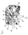
- the Fign. 1 and 2 show a liftable vehicle axle 10 provided with a crank 11 is to create space for a drive shaft 12.
- the vehicle axle 10 can by a lift bellows 13 are raised or lowered.
- the Liftbalg 13 is on the axle side with a Connecting arm 15 having holder 14 connected to the vehicle axle 10. Consequently the holder 14 extends with its connecting arm 15 from the upper end of the lifting bellows 13 down to the vehicle axle 10, where the connecting arm 15 is welded and / or can be screwed on.
- a round plate 27 is arranged.
- the Liftbalg 13 is also equipped with a cream-resistant Liftbalgexcellent 16 connected.
- the Liftbalg didactic 16 is attached to a frame side member 17.
- Liftbalgè 16 in addition to a frame rail 18 and / or on a Frame cross member 19 is connected.
- the lifting bellows 13 subjected to compressed air, whereby the lift bellows 13 rolls on a rolling piston 20 and thus its length is increased. Since the rolling piston 20 is firmly connected to the lifting bellows 16 is lifting the Liftbalg 13 when increasing its length attached to the lifting bellows 13 Holder 14 relative to the frame rails 17, 18, and 19.
- the vehicle axle 10 is at Lifts by a wishbone 21 and two trailing arms 22 and 23 parallel to the horizontal guided. By this horizontal orientation of the lifted vehicle axle 10 is an undesirable buckling of the connected to the vehicle axle 10 lift bellows 13th reliably excluded, whereby the life of the lifting bellows 13 increases significantly becomes.
- Fig. 3 shows an alternative to the connection of the holder 14 to a very heavily cranked vehicle axle 30.
- a fastening device 24 with a mounting plate 25 and cheeks 26 connects the holder 14 with the vehicle axle 30.
- the cheeks 26 engage around the vehicle axle 30.
- the fastening device 24 is positively connected to the vehicle axle 30 connected. Due to the positive connection between the fastening device 24 and the vehicle axle 30 can be introduced by the wishbone 21 transverse forces be transferred to the vehicle axle 30 via the fastening device 24.
- the holder 14 is connected by means of screws 28 with the mounting plate 25.
- the Fastening device 24 the wishbone 21 is hinged to the holder 14.
- it takes over the holder 14 in this variant two functions. First, it connects the upper one Area of the lifting bellows 13 by means of the circular plate 27 with the vehicle axis 30.
- the holder 14 serves as a point of articulation for the wishbone 21st
Landscapes
- Engineering & Computer Science (AREA)
- Mechanical Engineering (AREA)
- Chemical & Material Sciences (AREA)
- Combustion & Propulsion (AREA)
- Transportation (AREA)
- Vehicle Body Suspensions (AREA)
Applications Claiming Priority (2)
| Application Number | Priority Date | Filing Date | Title |
|---|---|---|---|
| DE2003133757 DE10333757A1 (de) | 2003-07-24 | 2003-07-24 | Vorrichtung zum Liften und Senken einer Fahrzeugachse |
| DE10333757 | 2003-07-24 |
Publications (3)
| Publication Number | Publication Date |
|---|---|
| EP1500580A2 true EP1500580A2 (fr) | 2005-01-26 |
| EP1500580A3 EP1500580A3 (fr) | 2006-09-13 |
| EP1500580B1 EP1500580B1 (fr) | 2008-07-30 |
Family
ID=33483047
Family Applications (1)
| Application Number | Title | Priority Date | Filing Date |
|---|---|---|---|
| EP20040015014 Expired - Lifetime EP1500580B1 (fr) | 2003-07-24 | 2004-06-25 | Dispositf pour relever et abaisser l'essieu d'un véhicule |
Country Status (2)
| Country | Link |
|---|---|
| EP (1) | EP1500580B1 (fr) |
| DE (2) | DE10333757A1 (fr) |
Cited By (1)
| Publication number | Priority date | Publication date | Assignee | Title |
|---|---|---|---|---|
| CN102658842A (zh) * | 2012-04-13 | 2012-09-12 | 领新(南通)重工有限公司 | 紧凑式高空车底盘扩桥系统 |
Families Citing this family (2)
| Publication number | Priority date | Publication date | Assignee | Title |
|---|---|---|---|---|
| BR102016024276A2 (pt) | 2016-10-18 | 2018-05-02 | Kll Equipamentos Para Transporte Ltda. | Dispositivo de suporte e conjunto de eixo auxiliar com drop |
| DE102019105566B4 (de) * | 2019-03-05 | 2023-01-05 | Benteler Automobiltechnik Gmbh | Fahrwerksanordnung für ein Kraftfahrzeug sowie Verfahren zum Betreiben eines Kraftfahrzeuges |
Citations (1)
| Publication number | Priority date | Publication date | Assignee | Title |
|---|---|---|---|---|
| EP1180474A2 (fr) | 2000-08-19 | 2002-02-20 | MAN Nutzfahrzeuge Aktiengesellschaft | Essieu pour véhicule utilitaire |
Family Cites Families (3)
| Publication number | Priority date | Publication date | Assignee | Title |
|---|---|---|---|---|
| IT1207545B (it) * | 1987-03-27 | 1989-05-25 | Viberti Off Spa | Dispositivo per il sollevamento di uno degli assali di un semirimorchio stradale e gruppo sollevatore facente parte di tale dispositivo |
| FR2640924B1 (fr) * | 1988-12-23 | 1991-09-13 | Trailor Sa | |
| DE29801179U1 (de) * | 1998-01-26 | 1998-04-16 | Paul Josef | Nachlauflenkachse für Lastkraftwagen |
-
2003
- 2003-07-24 DE DE2003133757 patent/DE10333757A1/de not_active Withdrawn
-
2004
- 2004-06-25 EP EP20040015014 patent/EP1500580B1/fr not_active Expired - Lifetime
- 2004-06-25 DE DE200450007714 patent/DE502004007714D1/de not_active Expired - Lifetime
Patent Citations (1)
| Publication number | Priority date | Publication date | Assignee | Title |
|---|---|---|---|---|
| EP1180474A2 (fr) | 2000-08-19 | 2002-02-20 | MAN Nutzfahrzeuge Aktiengesellschaft | Essieu pour véhicule utilitaire |
Cited By (1)
| Publication number | Priority date | Publication date | Assignee | Title |
|---|---|---|---|---|
| CN102658842A (zh) * | 2012-04-13 | 2012-09-12 | 领新(南通)重工有限公司 | 紧凑式高空车底盘扩桥系统 |
Also Published As
| Publication number | Publication date |
|---|---|
| DE502004007714D1 (de) | 2008-09-11 |
| DE10333757A1 (de) | 2005-02-17 |
| EP1500580A3 (fr) | 2006-09-13 |
| EP1500580B1 (fr) | 2008-07-30 |
Similar Documents
| Publication | Publication Date | Title |
|---|---|---|
| DE69414359T2 (de) | Lift-Achsen-Aufhängungssystem in Form eines Parallelogramms mit Steuerung der Achsen-Schwenkeinstellung | |
| DE60003694T2 (de) | Achsanhebevorrichtung unter fahrzeugrahmen | |
| EP2155508B1 (fr) | Essieu arrière pour véhicule à moteur | |
| DE10229161B4 (de) | Aufhängung mit einem Lenkgetrieberahmen | |
| WO2007087797A1 (fr) | Suspension de roue pour vehicule automobile | |
| EP0352541A1 (fr) | Suspension élastique d'essieu pour véhicules automobiles, notamment pour véhicules utilitaires | |
| EP1932799B1 (fr) | Chariot de manutention | |
| EP0332037B1 (fr) | Dispositif de relevage d'essieu | |
| EP0370217A2 (fr) | Suspension pour roue directrice de véhicule | |
| EP0961726A1 (fr) | Systeme de relevage d'axe de vehicule a suspension pneumatique | |
| EP4572966A1 (fr) | Système de guidage de voie | |
| DE69918012T2 (de) | Vorrichtung zum hochheben der achse eines fahrzeuges | |
| WO2013072152A1 (fr) | Essieu rigide à suspension pneumatique | |
| EP1500580B1 (fr) | Dispositf pour relever et abaisser l'essieu d'un véhicule | |
| EP0940319A2 (fr) | Chassis d'un véhicule utilitaire lourd | |
| EP2409861A1 (fr) | Unité de régulation de niveau | |
| EP4584105A1 (fr) | Structure d'essieu pour un châssis de véhicule utilitaire comprenant un pont d'essieu | |
| WO2024052477A1 (fr) | Structure d'essieu pour un châssis de véhicule utilitaire comprenant un pont d'essieu | |
| EP4335668A1 (fr) | Structure d'essieu pour un châssis de véhicule utilitaire doté d'un pont d'essieu conçu comme pièce moulée | |
| EP0502311B1 (fr) | Essieu à roues directrices et à suspension pneumatique pour véhicule à moteur | |
| DE69613478T2 (de) | Achsenkonstruktion für ein fahrzeug | |
| WO2024052479A1 (fr) | Structure d'essieu d'un châssis de véhicule utilitaire comportant un pont d'essieu | |
| DE10218406B4 (de) | Fahrzeugaufhängungssysteme | |
| EP0940324A1 (fr) | Chassis pour véhicule utilitaire lourd | |
| EP0940323B1 (fr) | Chassis pour véhicule utilitaire lourd |
Legal Events
| Date | Code | Title | Description |
|---|---|---|---|
| PUAI | Public reference made under article 153(3) epc to a published international application that has entered the european phase |
Free format text: ORIGINAL CODE: 0009012 |
|
| AK | Designated contracting states |
Kind code of ref document: A2 Designated state(s): AT BE BG CH CY CZ DE DK EE ES FI FR GB GR HU IE IT LI LU MC NL PL PT RO SE SI SK TR |
|
| AX | Request for extension of the european patent |
Extension state: AL HR LT LV MK |
|
| PUAL | Search report despatched |
Free format text: ORIGINAL CODE: 0009013 |
|
| AK | Designated contracting states |
Kind code of ref document: A3 Designated state(s): AT BE BG CH CY CZ DE DK EE ES FI FR GB GR HU IE IT LI LU MC NL PL PT RO SE SI SK TR |
|
| AX | Request for extension of the european patent |
Extension state: AL HR LT LV MK |
|
| 17P | Request for examination filed |
Effective date: 20061205 |
|
| 17Q | First examination report despatched |
Effective date: 20070123 |
|
| AKX | Designation fees paid |
Designated state(s): DE FR IT SE |
|
| GRAP | Despatch of communication of intention to grant a patent |
Free format text: ORIGINAL CODE: EPIDOSNIGR1 |
|
| GRAS | Grant fee paid |
Free format text: ORIGINAL CODE: EPIDOSNIGR3 |
|
| GRAA | (expected) grant |
Free format text: ORIGINAL CODE: 0009210 |
|
| AK | Designated contracting states |
Kind code of ref document: B1 Designated state(s): DE FR IT SE |
|
| REF | Corresponds to: |
Ref document number: 502004007714 Country of ref document: DE Date of ref document: 20080911 Kind code of ref document: P |
|
| REG | Reference to a national code |
Ref country code: SE Ref legal event code: TRGR |
|
| PLBE | No opposition filed within time limit |
Free format text: ORIGINAL CODE: 0009261 |
|
| STAA | Information on the status of an ep patent application or granted ep patent |
Free format text: STATUS: NO OPPOSITION FILED WITHIN TIME LIMIT |
|
| 26N | No opposition filed |
Effective date: 20090506 |
|
| REG | Reference to a national code |
Ref country code: FR Ref legal event code: CD |
|
| REG | Reference to a national code |
Ref country code: DE Ref legal event code: R081 Ref document number: 502004007714 Country of ref document: DE Owner name: MAN TRUCK BUS AG, DE Free format text: FORMER OWNER: MAN NUTZFAHRZEUGE AG, 80995 MUENCHEN, DE Effective date: 20110518 Ref country code: DE Ref legal event code: R081 Ref document number: 502004007714 Country of ref document: DE Owner name: MAN TRUCK & BUS AG, DE Free format text: FORMER OWNER: MAN NUTZFAHRZEUGE AG, 80995 MUENCHEN, DE Effective date: 20110518 |
|
| REG | Reference to a national code |
Ref country code: FR Ref legal event code: PLFP Year of fee payment: 13 |
|
| REG | Reference to a national code |
Ref country code: FR Ref legal event code: PLFP Year of fee payment: 14 |
|
| REG | Reference to a national code |
Ref country code: FR Ref legal event code: PLFP Year of fee payment: 15 |
|
| REG | Reference to a national code |
Ref country code: DE Ref legal event code: R081 Ref document number: 502004007714 Country of ref document: DE Owner name: MAN TRUCK & BUS SE, DE Free format text: FORMER OWNER: MAN TRUCK & BUS AG, 80995 MUENCHEN, DE |
|
| PGFP | Annual fee paid to national office [announced via postgrant information from national office to epo] |
Ref country code: SE Payment date: 20230317 Year of fee payment: 20 |
|
| PGFP | Annual fee paid to national office [announced via postgrant information from national office to epo] |
Ref country code: FR Payment date: 20230622 Year of fee payment: 20 Ref country code: DE Payment date: 20230627 Year of fee payment: 20 |
|
| PGFP | Annual fee paid to national office [announced via postgrant information from national office to epo] |
Ref country code: IT Payment date: 20230620 Year of fee payment: 20 |
|
| REG | Reference to a national code |
Ref country code: DE Ref legal event code: R071 Ref document number: 502004007714 Country of ref document: DE |
|
| REG | Reference to a national code |
Ref country code: SE Ref legal event code: EUG |