EP1500570B1 - Dispositif de blocage d'un colonne de direction réglable dans au moins un sens - Google Patents
Dispositif de blocage d'un colonne de direction réglable dans au moins un sens Download PDFInfo
- Publication number
- EP1500570B1 EP1500570B1 EP04012544A EP04012544A EP1500570B1 EP 1500570 B1 EP1500570 B1 EP 1500570B1 EP 04012544 A EP04012544 A EP 04012544A EP 04012544 A EP04012544 A EP 04012544A EP 1500570 B1 EP1500570 B1 EP 1500570B1
- Authority
- EP
- European Patent Office
- Prior art keywords
- teeth
- locking
- locking device
- adjustment
- counterlocking
- Prior art date
- Legal status (The legal status is an assumption and is not a legal conclusion. Google has not performed a legal analysis and makes no representation as to the accuracy of the status listed.)
- Expired - Lifetime
Links
- 238000006073 displacement reaction Methods 0.000 description 4
- 210000003746 feather Anatomy 0.000 description 3
- 238000010276 construction Methods 0.000 description 2
- 229910000831 Steel Inorganic materials 0.000 description 1
- 230000006978 adaptation Effects 0.000 description 1
- 230000015572 biosynthetic process Effects 0.000 description 1
- 238000005553 drilling Methods 0.000 description 1
- 230000000694 effects Effects 0.000 description 1
- 238000000034 method Methods 0.000 description 1
- 239000000203 mixture Substances 0.000 description 1
- 238000012986 modification Methods 0.000 description 1
- 230000004048 modification Effects 0.000 description 1
- 239000010959 steel Substances 0.000 description 1
Images


Classifications
-
- B—PERFORMING OPERATIONS; TRANSPORTING
- B62—LAND VEHICLES FOR TRAVELLING OTHERWISE THAN ON RAILS
- B62D—MOTOR VEHICLES; TRAILERS
- B62D1/00—Steering controls, i.e. means for initiating a change of direction of the vehicle
- B62D1/02—Steering controls, i.e. means for initiating a change of direction of the vehicle vehicle-mounted
- B62D1/16—Steering columns
- B62D1/18—Steering columns yieldable or adjustable, e.g. tiltable
- B62D1/184—Mechanisms for locking columns at selected positions
Definitions
- the invention relates to a locking device of an adjustable in at least one adjustment steering column, with at least one of the adjustment or one of the adjustment directions associated locking part, which has at least a first and at least a second toothing, and at least one of these adjustment associated Gegenfest scholaril which at least a first and at least a second counter-toothing, and having an openable and closable clamping device, in the open state, the first and second gears are spaced from the first and second counter teeth and in the closed state, the locking member and the counter-locking member are in mesh with each other, wherein the teeth the teeth and the counter teeth extend transversely to this adjustment and successive teeth of the teeth and counter teeth each have equal distances from each other and the tips de r teeth of the teeth and counter teeth are each in planes.
- Adjustable steering columns are known in different embodiments. Usually, both the length of the steering column and its inclination or height in the open state of the locking device can be changed in this case.
- intersecting packets of fins can be provided, one of which is fixed to the jacket tube and the other on a chassis-fixed console part and which are penetrated by a clamping bolt and clamped by means of the clamping device become.
- Such an adjustable steering column is known for example from EP 0 802 104 B1. To enable the adjustment intersecting slots are arranged in the disk packs and in the jacket tube and in the console part, which are penetrated by the clamping bolt.
- a disadvantage of steering columns with locking devices having slats it is, inter alia, that the achievable holding forces are limited to the friction in the closed state and that even to achieve the highest possible holding force in the closed state, a relatively large number of slats is required Even in the open state of the locking device, a relatively large frictional force for adjusting the steering column is overcome.
- an adjustable steering column with a locking device of the aforementioned type is known in which toothed parts are present whose teeth engage in one another in the closed state of the locking device.
- the adjustment of the steering column is very smooth when opened.
- it may occur in such a locking device the problem that the tips of the teeth of the opposing teeth are directly opposite (tooth-on-tooth position) and meet when closing the clamping device, so that the locking device can not be properly closed , In the event of a crash, this may result in an uncontrolled shift of the steering column.
- the closing of the clamping device in the case of Aufong Economicsehs the tips of the teeth is not possible or not completely or only under greatly increased force or only after a further adjustment of the steering column.
- the object of the invention is to provide a locking device of the type mentioned, which is easily closable in any adjustment of the steering column and holds the steering column securely in the set position.
- both the tips of the teeth of the first toothing and the first counter toothing and the tips of the teeth of the second toothing and the second counter toothing simultaneously in a directly opposite position (head-to-head position) are located.
- all adjustment positions of the steering column in the adjusting part and the counter-locking part associated adjustment reach the teeth of one of the two gears with the teeth of the corresponding counter teeth in the closed state of the clamping device at least. In particular, this makes it possible to achieve stepless adjustability of the steering column in the relevant adjustment direction.
- the locking device is designed at least for the height adjustment of the steering column in the manner according to the invention.
- the locking part of a cooperating with a clamping bolt of the clamping device clamping plate and the counter-locking part can be formed by a side cheek of a chassis-fixed console part.
- the clamping bolt passes through a recess in a jacket tube supporting the steering shaft and further formed as a slot recess in the counter-locking part. About this Langlochaus founded in the counter-locking part of the clamping bolt against the counter-locking part in the direction of height adjustment is limited.
- the clamping part forming the locking part is arranged on the clamping bolt, which passes through a hole.
- the locking part is moved with the clamping bolt in this adjustment, while the counter-locking part formed by the side cheek is non-displaceable as part of the chassis fixed console part in the adjustment.
- a manually operable clamping lever may be provided or this can be done by motor.
- the teeth of the teeth and counter teeth which extend transversely along straight lines, preferably substantially perpendicular, to this adjustment, are brought into engagement with each other.
- Embodiments of the invention are conceivable and possible, in which formed in the manner of the invention locking parts and Gegenfest technicallyile be used in connection with the longitudinal adjustment of the steering column.
- a jacket tube supporting the steering column could be mounted so as to be displaceable in the longitudinal direction on a guide rail, the guide rail being mounted so as to be pivotable about an axis lying transversely to the jacket tube.
- a clamping bolt of a clamping device in this case passes through an elongated hole extending in the direction of the longitudinal adjustment in the jacket tube and carries at its end located inside the jacket tube a clamping plate.
- Such a construction is known, for example, from EP 0 836 981 B1.
- the clamping plate carried by the clamping bolt and arranged inside the jacket tube could form the locking part and have the first and second teeth and the counter-locking part could be arranged on the inside of the jacket tube or be formed by a section of the jacket tube and those with the first and second having second teeth cooperating first and second counter teeth.
- the fixation of the height adjustment could be done in such a construction in the manner according to the invention.
- a sufficient clearance between the locking part and the counter-locking part can be provided or the teeth and / or counter teeth are slidably disposed on the locking part or counter-locking part.
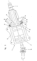
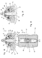
- the exemplary embodiment of a steering column shown in the figures comprises in a conventional manner a steering spindle 1, which is received at least in sections by a jacket tube 2 and is rotatable relative thereto.
- the jacket tube 2 is limited relative to a console part 3 adjustable.
- the steering shaft 1 is adjustable in length and height or tilt adjustable.
- the steering shaft 1 in a conventional manner on two telescopic sections 4, 5.
- pivoting of the steering shaft 1 and the casing tube 2 takes place about a pivot axis 6, wherein simultaneously with the height adjustment of the steering shaft 1 in the region of its front end to which a steering wheel is mounted, a tilt adjustment lying in the region of the front end 7 Longitudinal axis 8 of the steering spindle takes place.
- the pivot axis 6 can be formed, for example, by providing the steering spindle 1 rotatably receiving and surrounding this annular part having on both sides protruding bolts which are rotatably received in tabs 9 of the console part 3. At the portion 5 of the steering shaft 1 close a universal joint 10 and another section 11th the steering shaft, which is only partially shown in the figures.
- the parts of the steering shaft, not shown, may be formed in a conventional manner.
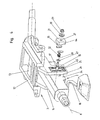
- the console part 3 has a mounting part 12 for attachment to the chassis of a vehicle.
- a support plate 13 is held, which may be rigidly connected to the mounting part. But it can also be the support plate 13 clamped in the mounting part 12 in a defined manner, in the event of a crash, a displacement of the support plate 13 in the axial direction of the steering shaft relative to the mounting member 12 is possible, as has already become known in conventional steering columns. In normal operation, however, there is an immovable connection between the carrier plate 13 and the mounting part 12.
- the locking device comprises a clamping device which can be opened and closed in the illustrated embodiment via a manually operable clamping lever 16.
- a rotatably mounted on a clamping bolt 17 cam plate 18 is pivoted about the axis 19 of the clamping bolt 17.
- a locking part 21 is further arranged, which is penetrated by the clamping bolt 17 through a bore in the same.
- inclined surfaces 22 which cooperate with cam 23 of the cam plate 18.
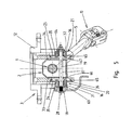
- the clamping bolt passes through a further perpendicular to the longitudinal axis 8 of the steering shaft perpendicular to the longitudinal axis 8 of the steering shaft 1 in the direction of height adjustment extending slot 24 in the counter-locking part 14, in the direction of the longitudinal axis 8 extending slot 26 in the casing tube 2 and a perpendicular to the longitudinal axis 8 of Steering spindle 1 in the direction of height adjustment extending slot 25 in the counter-locking part 15.
- On the protruding from the counter-locking part 15 portion of the clamping bolt 17 is further arranged by the clamping bolt 17 through a bore 27 clamping plate, which forms a further locking part 21.
- the cam plate 18 and the locking part 21 are based on their side facing away from the steering shaft 1 side surfaces against the head 28 of the clamping bolt 17 on the one hand and on the opposite threaded end of the clamping bolt 17 screwed nut 29 or an intermediate Achsiallager 30 from.
- the locking parts 20, 21 are secured against pivoting about the axis of the clamping bolt 17 relative to the counter-locking parts 14, 15.
- the locking members 20, 21 in the embodiment shown on both sides of their bores 27 passing through clamping bolt 17 lugs 35, 36 which protrude into the slots 24, 25 of the counter-locking parts 14, 15, in the open state of the clamping device or when closing the tensioning device as a guide between the locking parts 20, 21 and the counter-locking parts 14, 15 to serve.
- the locking parts 20, 21 are provided with toothed strips 37.
- the toothed racks in recesses of base bodies 63, 64 of the locking members 20, 21 used and rigidly connected to the main bodies 63, 64.
- a one-piece design of the toothed racks 37 with the basic bodies 63, 64 would be conceivable and possible.
- Each rack 37 has a first and a second teeth 38, 39, wherein the first teeth 38 with first counter teeth 40 and the second teeth 39 with second counter teeth 41 of the counter-locking parts 14, 15 cooperate.
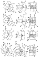
- 10 to 21 are a portion of a rack 37 with the sections of the teeth 38, 39 arranged thereon and a portion of a counter-locking part 14 with portions of the counter teeth 40, 41 cooperating with the teeth 38, 39 (eg Insert parts 65 of the counter-locking parts 14, 15 are arranged) is shown.
- the teeth 38, 39 and counter teeth 40, 41 each have a series of teeth 42 to 45, all of which extend transversely to the direction indicated in FIGS. 10 and 12 by double arrows adjustment 46, in this case the height adjustment.
- the tips of the teeth extend along straight lines which lie transversely to the adjustment direction, preferably perpendicular to the adjustment direction 46.
- the straight lines along which the tips of the teeth 42 to 45 extend lie in this case parallel to each other for all the teeth of a respective toothing 38, 39 and a respective counter toothing 40, 41.
- these lines are further for the teeth 42 of the first toothing parallel to the teeth 44 of the first counter toothing and the teeth 43 of the second toothing parallel to the teeth of the second counter toothing, both in the closed and in the open state of the clamping device ,
- the teeth 42 to 45 all have the same distances a from each other, these distances a being measured, for example, between the tips of adjacent teeth.
- the tips of the teeth 42 of the first gear 38 lie in a common plane 47, as are the tips of the teeth 43 of the second gear in a common plane 48.
- the tips of the teeth 44 of the first counter-toothing 40 lie in a common plane 49 and the tips the teeth 45 of the second counter teeth 41 lie in a common plane 50.
- the plane 47 of the tips of the teeth 42 of the first teeth 38 and the plane 48 of the tips of the teeth 43 of the second teeth 39 are V-shaped and close an angle 51 between yourself.
- the first toothing 38 and second toothing 39 together form a type of arrow toothing.
- the plane 49 of the tips of the teeth 44 of the first counter teeth 40 and the plane 50 of the teeth 45 of the second counter teeth 41 are also V-shaped to each other and include the same angle 51 with each other.
- the first gear 38 is associated Level 47 parallel to the first counter-toothing 40 associated level 49 and the second toothing 39 associated level 48 parallel to the second counter teeth 41 associated level 50.
- the counter teeth 40, 41 are seen in a cross-sectional or side view (Fig. 11) arranged substantially V-shaped recess in the counter-locking part 14.
- the tips of these teeth are not in the same places with respect to a parallel to the adjustment direction 46 extending axis.
- the offset v between the teeth 44 of the first counter teeth 40 and the teeth 45 of the second counter teeth 41 in this embodiment is just half the distance between two consecutive teeth 44 and 45. It could also be said, the first and second counter teeth 40, 41 are out of phase with each other, in this embodiment by 90 ° out of phase (corresponding to a half tooth), while the teeth 42, 43 of the first and second teeth 38, 39 have the same phase position.
- the teeth 42, 44 of the first toothing 38 and the first counter toothing 40 can not assume a head-to-head position simultaneously with the teeth 43, 45 of the second toothing 39 and second counter toothing, as shown for example in FIG 21 can be seen.
- the tips of the teeth 43 of the second toothing 39 are here exactly opposite the tips of the teeth 45 of the second counter toothing 41, while the tips of the teeth 42, of the first toothing 38 oppose the valleys between the teeth 44 of the first counter toothing 40. If the clamping device in this Closed adjustment position of the steering column, so while the head-to-head position of the teeth 43 of the second teeth 39 with the teeth 45 of the second counter teeth 41 remain (right in Fig.
- the teeth 42 of the first teeth 38 but come with the teeth 44 of the first counter-toothing 40 completely engaged (right side in Fig. 21).
- the toothed bar 37 is shifted relative to the central position between the first and second counter-toothing 40, 41 by a distance s1 to the left. This position of the rack 37 automatically adjusts when closing the clamping device, as between the clamping bolt 17 and the counter-locking part 14 and between the clamping bolt 17 and the locking member 20 and 21 is a total sufficient clearance.
- FIGS. 13 to 15 and 16 to 18 Slightly different adjustment positions of the steering column, in which the tensioning device has been closed, are shown in FIGS. 13 to 15 and 16 to 18, respectively.
- Figs. 13 to 15 a central position between head-to-head positions on both sides can be seen, wherein the rack 37 is not offset from the central position between the counter teeth 40, 41, and in Figs. 16 to 18 is a Between the positions of Fig. 19 to 21 and 13 to 15 shown, wherein the lateral offset of the rack 37 with respect to the center position between the counter teeth 40, 41 is a smaller compared to FIG. S2 s2 (half of s1).
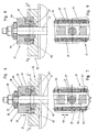
- the first and second counter teeth 40, 41 are arranged in this embodiment of the invention on inserts 65 of the counter-locking part 15 (or 14).
- the tooth layers between the teeth 38, 39 and counter teeth 40, 41 are identical in this embodiment on both sides of the clamping bolt 17 (left and right of the clamping bolt in Figs. 6 and 8).
- each have a locking part 20, 21 and associated Gegenfestabilityil 14, 15 available is, it would also be possible and possible to provide only one locking part 20 and 21 with associated Gegenfestitatiil 14 and 15 on one side of the steering shaft 1.
- the function according to the invention could in principle also be achieved only with a toothed bar 37 arranged on the locking part 20 or 21, the toothings 38, 39 of which interact with counter toothings 40, 41 in the counter-locking part 14 or 15.
- the first gear 38 and the counter-locking part 14 and 15 cooperating with their first counter teeth 40 on one side with respect to the clamping bolt 17 and the slot 24 and 25 and the second gear 39 and the associated second counter teeth 41 on the other side with respect to the clamping bolt 17 and the slot 24 and 25 to arrange.
- clamping device instead of the described clamping device, this could also be formed in another way, as long as locking part 20, 21 and counter-locking part 14, 15 are spaced apart in the open state of the clamping device and are clamped together in the closed state of the clamping device.
- Different tensioning devices have become known in connection with steering columns, which could be used for this purpose.
- the invention is not limited to the fixation of the height or inclination adjustment of the steering column, but instead or in addition thereto, the invention could also be used in connection with the fixing of the length adjustment of a steering column.
- the invention can be used in an advantageous manner.
- the toothed strips 37 with the toothings 38, 39 and the counter teeth 40, 41 may also be curved in the form of a circular arc (with the pivot axis 6) as the center.
- a spring device 52 acts between the locking part 20 or 21 and the counter-locking part 14, 15.
- This spring device 52 is formed by a spring 53 arranged in a recess of the locking part 20, 21. which carries a sliding pin 54, which is supported against a locking part 20, 21 cross, formed with a low surface friction extension 55 of the counter-locking part 14, 15.
- On the opposite side of the locking part 20, 21 a further the locking part 20, 21 cross-guide extension 56 is arranged, on which the locking part 20, 21 slides during adjustment and also slides when opening and closing the clamping device. It should thereby be achieved regardless of the present before closing the clamping device adjustment position a clamped position in which the teeth are on the one hand completely with the counter teeth in engagement, as shown in Fig. 23.
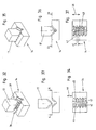
- FIGS. 24 and 25 A further embodiment of the invention is shown in FIGS. 24 and 25.
- the teeth 38, 39 and counter teeth 40, 41 on both sides of the clamping bolt 17 are identical.
- the first toothing 38 and second toothing 39 on the one side (left in FIG. 24) with respect to the clamping bolt 17 are, however, opposite the first toothing 38 and second toothing 39 on the other side (on the right in FIG. 24) with respect to the clamping bolt in the adjustment direction 46 offset by an amount d, which corresponds to a part of the distance a between successive teeth, z. B. corresponds to half the distance between successive teeth.
- d corresponds to a part of the distance a between successive teeth
- z. B. corresponds to half the distance between successive teeth.
- this is achieved, for example, by the fact that the two toothed strips 37 are shifted relative to one another by the amount d in the adjustment direction 46. Further, the distance b1 between the medial planes between the first and second serrations 38, 39 is different from the distance b2 between the medial planes between the first and second counter serrations 40, 41. In this way it is achieved that a head-to-head position of one of the two teeth 38, 39 with one of the two counter teeth 40, 41 always only on one side of the clamping bolt 17 may be present simultaneously, whereby the security of the fixation of the adjustment is increased again (a zigzag-shaped slippage between the rack teeth 37 and the counter teeth 40, 41 is blocked). Instead of the offset of the teeth 38, 39 and the counter teeth 40, 41 could be offset (or in addition thereto).
- 26 to 31 show an embodiment of the invention in which a respective toothed bar 37 is mounted displaceably relative to the fixing part 20 both in the closing direction 57 and in the direction 58 perpendicular to the adjusting direction 46 and closing direction 57.
- the base 63 has an undercut groove 59, in which the game with respect to the undercut groove 59 mounted ("floating") rack 37 protrudes, wherein on the rack 37 lateral stop projections 60, 61 are mounted in the undercut areas of the groove 59 protrude.
- a spring means 62 biases the rack 37 in the fully extended position, in which the stop projections 60, 61 abut the undercut edges of the groove 59.
- the toothed bar 37 When closing the clamping device, the toothed bar 37 is pressed against the force of the spring 62 with its stop projections 60, 61 to the groove base and can thereby move in adaptation to the counter teeth 40, 41 in the direction 58.
- An example of a fully closed state is shown in FIGS. 29 to 31. Due to this design of the locking member 20, it is not necessary for the required when closing the clamping device in dependence on the adjustment between the gears 38, 39 and the counter teeth 40, 41 in the direction 58 that a correspondingly large game between the locking member 20 and the Clamping pin 17 and / or between the clamping bolt 17 and the counter-locking part 14 is present.
- the toothed strip 37 may be pivotably mounted relative to the base body about an axis lying parallel to the adjustment direction 46, in order to enable an adjustment of the teeth 38, 39 in the direction 58 (FIG. 27) when the clamping device is closed.
- the teeth 38, 39 and the toothed strips 37 and the counter teeth 40, 41 may be formed bent.
- FIGS. 32 to 37 show an exemplary embodiment in which the offset v in the adjustment direction 46 between the teeth is not between the first and second counter teeth 40, 41 but between the first and second teeth 38, 39 is present.
- FIGS. 38 to 40 A further embodiment of the invention is shown in FIGS. 38 to 40. It is here a rack 37 is provided which has a passage opening 68 for the passage of the clamping bolt 17, which is designed here as Langlochaus principleung to allow adjustment of the rack 37 in the direction 58 perpendicular to the closing direction 57 and the adjustment direction 46.
- the rack is as in the embodiment of FIGS. 26 to 31 in an undercut groove 59 of the locking part 21 "floating" stored, d. H. she has a game in the direction of 58. It is further parallel to the closing direction 57 against the Grundgroprer 64 of the locking member 21 slidably.
- a spring device 62 biases the toothed bar 37 outwards, and in the opened state of the clamping device, the stop projections 60, 61 abut against the undercut edges (FIG. 39).
- first and second teeth 38, 39 are arranged, which are arranged in this embodiment with respect to the clamping bolt 17 opposite sides of the rack 37 (left and right of the clamping bolt 17 in Figs. 38 to 40).
- the teeth 38, 39 act in turn in the manner already described together with counter teeth 40, 41, which are arranged on the counter-locking part 15, here on an insert part 65 thereof.
- the counter teeth 40, 41 are corresponding to the teeth 38, 39 with respect to the clamping bolt 17 opposite sides of the counter-locking part 15th
- This embodiment according to FIGS. 38 to 40 could be modified, for example, to the effect that the toothed bar 37 is rigidly connected to the locking parts 21, the locking part 21 being opposite the counter-locking part 15 has a sufficient clearance in the direction 58 to allow adjustment of the rack 37 against the counter-locking part 15 in this direction.
- the locking parts 20, 21 could, for example, be machined without cutting or as sintered parts or from stamped sheet steel by a deep drawing process. The same applies to the counter-locking parts or arranged therein, the counter-teeth having inserts.
- the insert parts 65 may also be omitted and the Jacobfestberichtile could be integrally formed.
Landscapes
- Engineering & Computer Science (AREA)
- Chemical & Material Sciences (AREA)
- Combustion & Propulsion (AREA)
- Transportation (AREA)
- Mechanical Engineering (AREA)
- Steering Controls (AREA)
Claims (21)
- Dispositif de blocage d'une colonne de direction réglable dans au moins un sens de réglage (46), comprenant- au moins un élément de blocage (20, 21) associé au sens de réglage (46) ou à un des sens de blocage, et présentant au moins une première et au moins une deuxième denture (38, 39), et- au moins un élément de blocage antagoniste (14, 15) associé à ce sens de réglage (46), et présentant au moins une première et au moins une deuxième denture antagonistes (40, 41), et- un dispositif de serrage pouvant être ouvert et fermé, dont l'état ouvert tient les première et deuxième dentures (38, 39) écartées des première et deuxième dentures antagonistes (40, 41), et dont l'état fermé engrène l'élément de blocage (20, 21) et l'élément de blocage antagoniste (14, 15) l'un dans l'autre,- les dents des dentures (38, 39) et des dentures antagonistes (40, 41) étant transversales à ce sens de réglage (46) avec des dents successives (42 à 45) des dentures (38, 39) et des dentures antagonistes (40, 41) présentant respectivement les mêmes distances les unes des autres, alors que les pointes des dents (42 à 45) des dentures (38, 39) et des dentures antagonistes (40, 41) se situent respectivement dans des plans (47 à 50),caractérisé en ce que
le plan (47) des pointes des dents (42) de la première denture (38) et le plan (48) des pointes des dents (43) de la deuxième denture (39) sont disposés en forme de V les uns par rapport aux autres en enfermant un angle (51), et le plan (49) des pointes des dents (44) de la première denture antagoniste (40) et le plan (50) des pointes des dents (45) de la deuxième denture antagoniste (41) sont disposés en forme de V les uns par rapport aux autres en enfermant le même angle (51), et un décalage (v) correspondant à une partie de la distance (a) entre des dents successives (42 à 45) est présent entre les dents (42) de la première denture (38) et les dents (43) de la deuxième denture (39) ou entre les dents (44) de la première denture antagoniste (40) et les dents (45) de la deuxième denture antagoniste (41). - Dispositif de blocage selon la revendication 1,
caractérisé en ce que
le décalage (v) correspond à la moitié de la distance (a) entre des dents successives (42 à 45). - Dispositif de blocage selon la revendication 1 ou 2,
caractérisé en ce que
les première et deuxième dentures (38, 39) sont sur un rail denté (37) prévu sur ou dans un corps de base (63, 64) de l'élément de blocage (20, 21). - Dispositif de blocage selon la revendication 3,
caractérisé en ce que
le rail denté (37) est relié rigidement ou formé d'une seule pièce avec le corps de base (63, 64) de l'élément de blocage (20, 21). - Dispositif de blocage selon la revendication 3,
caractérisé en ce que
le rail denté (37) est logé en déplacement limité par rapport au corps de base (63, 64) de l'élément de blocage (20, 21) dans un sens (58) perpendiculaire au sens de réglage (46) et perpendiculairement à un sens de fermeture (57) dans lequel l'élément de blocage (20, 21) et l'élément de blocage antagoniste (14, 15) s'approchent l'un de l'autre lors de la fermeture du dispositif de serrage. - Dispositif de blocage selon la revendication 5,
caractérisé en ce que
le rail denté (37) est logé en déplacement limité par rapport au corps de base (63, 64) de l'élément de blocage (20, 21) à l'encontre de la force d'un dispositif de ressort (62) dans le sens de fermeture (57) ou à l'opposé de celui-ci. - Dispositif de blocage selon l'une quelconque des revendications 1 à 6,
caractérisé en ce que
la première et la deuxième dentures antagonistes (40, 41) sont disposées dans l'élément de blocage antagoniste (14, 15) dans un creux pour l'essentiel en forme de V, observé en coupe transversale. - Dispositif de blocage selon l'une quelconque des revendications 1 à 7,
caractérisé en ce qu'
entre l'élément de blocage (20, 21) et l'élément de blocage antagoniste (14, 15) agit un dispositif de ressort (52) qui charge l'élément de blocage (20, 21) par rapport à l'élément de blocage antagoniste (14, 15) dans le sens perpendiculaire au sens de réglage (46) et perpendiculaire au sens de fermeture (57), et qui l'applique contre un appendice de guidage (56) de l'élément de blocage antagoniste (14, 15). - Dispositif de blocage selon l'une quelconque des revendications 1 à 8,
caractérisé en ce que
l'élément de blocage (20, 21) est traversé par un boulon de serrage (17) du dispositif de serrage à travers un alésage (27) et déplacé par le boulon de serrage (17), lors de la fermeture du dispositif de serrage, dans le sens axial du boulon de serrage (17) contre l'élément de blocage antagoniste (14, 15). - Dispositif de blocage selon l'une quelconque des revendications 1
à 9,
caractérisé en ce que
le sens de réglage (46) est le sens de réglage de la hauteur ou de l'inclinaison de l'arbre de direction (1) de la colonne de direction. - Dispositif de blocage selon la revendication 10,
caractérisé en ce que
l'élément de blocage antagoniste (14, 15) est formé par une joue latérale d'un élément de console (3) solidaire du châssis s'étendant à côté d'un tube enveloppe (2), qui reçoit au moins en partie l'arbre de direction (1) de la colonne de direction, et présente un trou oblong (24, 25) traversé par le boulon de serrage (17) du dispositif de serrage. - Dispositif de blocage selon l'une quelconque des revendications 1 à 11,
caractérisé en ce qu'
il présente deux éléments de blocage (20, 21) et deux éléments de blocage antagonistes (14, 15) engrenés dans ceux-ci à l'état fermé du dispositif de blocage et munis d'une première et d'une deuxième dentures (38, 39) respectives ou d'une première et d'une deuxième dentures antagonistes (40, 41). - Dispositif de blocage selon l'une quelconque des revendications 1 à 12,
caractérisé en ce que
l'élément de blocage (20, 21) présente deux premières et deux deuxièmes dentures (38, 39), et l'élément de blocage antagoniste (14, 15) présente deux premières et deux deuxièmes dentures antagonistes (40, 41) engrenées dans les dentures (38, 39) de l'élément de blocage (20, 21) à l'état fermé du dispositif de serrage. - Dispositif de blocage selon la revendication 13,
caractérisé en ce que
deux rails dentés (37) disposés sur l'élément de blocage (20, 21) se situent de part et d'autre du boulon de serrage (17) et présentent chacun une première et une deuxième dentures (38, 39). - Dispositif de blocage selon la revendication 13 ou 14,
caractérisé en ce que
les deux premières dentures (38) et les deux deuxièmes dentures antagonistes (39) sont décalées les unes par rapport aux autres dans le sens de réglage (46) d'un intervalle (d) qui correspond à une partie de la distance (a) entre des dents successives (42, 43). - Dispositif de blocage selon l'une quelconque des revendications 13 à 15,
caractérisé en ce que
les deux premières dentures antagonistes (40) et les deux deuxièmes dentures antagonistes (41) sont décalées les unes par rapport aux autres dans le sens de réglage (46) d'un intervalle qui correspond à une partie de la distance (a) entre des dents successives (44, 45). - Dispositif de blocage selon la revendication 15 ou 16,
caractérisé en ce que
la distance (b1) entre les plans médians entre la première et la deuxième dentures (38, 39) diffère de la distance (b2) entre les plans médians entre la première et la deuxième dentures antagonistes (40, 41). - Dispositif de blocage selon l'une quelconque des revendications 3 à 12,
caractérisé en ce que
le rail denté (37) présente une ouverture de passage (68) pour le passage du boulon de serrage (17), et la première denture (38) ainsi que la deuxième denture (39) se situent sur des faces du rail denté tournées l'une vers l'autre par rapport au boulon de serrage (17), et les dentures antagonistes (40, 41) associées de l'élément de blocage antagoniste (15) se situent par analogie sur des faces de l'élément de blocage antagoniste (15) tournées l'une vers l'autre par rapport au boulon de serrage (17). - Dispositif de blocage selon la revendication 18,
caractérisé en ce que
le boulon de serrage (17) traverse l'ouverture de passage (68) avec jeu dans un sens (58) perpendiculaire au sens de fermeture (57) et au sens de réglage (46). - Dispositif de blocage selon l'une quelconque des revendications 1 à 19,
caractérisé en ce que
lors d'un réglage de l'arbre de direction (1) de la colonne de direction dans le sens de réglage (46), l'élément de blocage (20, 21) ou l'élément de blocage antagoniste (14, 15) est déplacé avec l'arbre de direction (1), alors que le deuxième élément n'est pas déplaçable dans ce sens de réglage par rapport à un élément de console (3) solidaire du châssis et portant l'arbre de direction (1) ou un tube enveloppe (2) logeant l'arbre de direction (1). - Dispositif de blocage selon l'une quelconque des revendications 1 à 20,
caractérisé en ce qu'
à l'état ouvert du dispositif de serrage, un dispositif de ressort (31, 32, 69) distancie l'élément de blocage (20, 21) par rapport à l'élément de blocage antagoniste (14, 15), et les dentures (38, 39) ne sont pas engrenées dans les dentures antagonistes (40, 41).
Applications Claiming Priority (2)
| Application Number | Priority Date | Filing Date | Title |
|---|---|---|---|
| DE10333228 | 2003-07-21 | ||
| DE10333228A DE10333228A1 (de) | 2003-07-21 | 2003-07-21 | Feststelleinrichtung einer in mindestens eine Verstellrichtung verstellbaren Lenksäule |
Publications (3)
| Publication Number | Publication Date |
|---|---|
| EP1500570A2 EP1500570A2 (fr) | 2005-01-26 |
| EP1500570A3 EP1500570A3 (fr) | 2005-04-13 |
| EP1500570B1 true EP1500570B1 (fr) | 2006-07-26 |
Family
ID=33483007
Family Applications (1)
| Application Number | Title | Priority Date | Filing Date |
|---|---|---|---|
| EP04012544A Expired - Lifetime EP1500570B1 (fr) | 2003-07-21 | 2004-05-27 | Dispositif de blocage d'un colonne de direction réglable dans au moins un sens |
Country Status (5)
| Country | Link |
|---|---|
| US (1) | US7325467B2 (fr) |
| EP (1) | EP1500570B1 (fr) |
| AT (1) | ATE334032T1 (fr) |
| DE (2) | DE10333228A1 (fr) |
| ES (1) | ES2268540T3 (fr) |
Families Citing this family (39)
| Publication number | Priority date | Publication date | Assignee | Title |
|---|---|---|---|---|
| DE102004018902B3 (de) | 2004-04-15 | 2006-01-12 | Thyssenkrupp Presta Ag | Feststelleinrichtung einer zumindest höhenverstellbaren Lenksäule |
| US7861615B2 (en) * | 2005-04-19 | 2011-01-04 | Gm Global Technology Operations, Inc. | Adjustable steering column assembly |
| US20060230863A1 (en) * | 2005-04-19 | 2006-10-19 | Delphi Technologies, Inc. | Steering column with rake and telescope adjustment |
| US8056437B2 (en) | 2005-04-19 | 2011-11-15 | Nexteer (Beijing) Technology Co., Ltd. | Electric steering column lock with single direction actuator travel |
| JP5061900B2 (ja) * | 2005-05-06 | 2012-10-31 | 日本精工株式会社 | ステアリングコラム装置 |
| DE102005036582A1 (de) * | 2005-08-01 | 2007-02-08 | Thyssenkrupp Presta Ag | Verstellbare Lenksäule für ein Kraftfahrzeug |
| JP5131425B2 (ja) * | 2005-11-21 | 2013-01-30 | 日本精工株式会社 | ステアリングコラム装置 |
| KR20070075111A (ko) * | 2006-01-12 | 2007-07-18 | 주식회사 만도 | 텔레스 제 2 기어와 텔레스 제 1 기어를 구비한 텔레스코프조향장치 |
| DE102007003091B3 (de) * | 2007-01-16 | 2008-08-07 | Thyssenkrupp Presta Ag | Verstellbare Lenksäule für ein Kraftfahrzeug |
| KR100848500B1 (ko) * | 2007-01-31 | 2008-07-28 | 주식회사 만도 | 틸트 및 텔레스코프 조향장치 |
| GB0723485D0 (en) | 2007-11-30 | 2008-01-09 | Trw Das A S | Adjustable steering column assembly |
| US7819426B2 (en) * | 2008-04-24 | 2010-10-26 | Gm Global Technology Operations, Inc. | Over-center locking mechanism for steering column assembly |
| DE102008024405A1 (de) | 2008-05-20 | 2010-01-28 | Thyssenkrupp Presta Ag | Spannbolzen für eine Feststelleinrichtung einer verstellbaren Lenksäule |
| DE102009014275A1 (de) | 2009-03-20 | 2009-10-29 | Daimler Ag | Verstelleinrichtung zum Verstellen einer Lenksäule in einem Kraftfahrzeug |
| DE102010016679B4 (de) | 2010-04-28 | 2012-07-12 | Thyssenkrupp Presta Ag | Spannteil für eine in einer verstellbaren Lenksäule für ein Kraftfahrzeug integrierte Spannvorrichtung |
| DE102010020633A1 (de) * | 2010-05-14 | 2011-11-17 | Gm Global Technology Operations Llc (N.D.Ges.D. Staates Delaware) | Lenksäule für ein Kraftfahrzeug |
| EP2625087B1 (fr) * | 2010-10-08 | 2015-01-07 | TRW Steering Systems Poland Sp. z.o.o. | Ensemble colonne de direction |
| DE102011109691A1 (de) * | 2011-08-06 | 2013-02-07 | Daimler Ag | Lenkspindelanordnung |
| DE102011054606B3 (de) | 2011-10-19 | 2013-02-28 | Thyssenkrupp Presta Aktiengesellschaft | Lenkspindellagereinheit zur drehbaren Lagerung einer Lenkspindel |
| DE102011054598B3 (de) | 2011-10-19 | 2013-01-17 | Thyssenkrupp Presta Ag | Lenkspindellagereinheit zur drehbaren Lagerung einer Lenkspindel |
| DE102011054597A1 (de) | 2011-10-19 | 2013-04-25 | Thyssenkrupp Presta Aktiengesellschaft | Lenkspindellagereinheit |
| DE102011056674B3 (de) * | 2011-10-19 | 2012-12-06 | Thyssenkrupp Presta Aktiengesellschaft | Lenksäule für ein Kraftfahrzeug |
| US20130174684A1 (en) * | 2012-01-11 | 2013-07-11 | International Truck Intellectual Property Company, Llc | Steering column adjustment |
| GB201300262D0 (en) * | 2013-01-08 | 2013-02-20 | Trw Ltd | Clamp assembly for a steering column assembly |
| FR3038571B1 (fr) * | 2015-07-10 | 2019-03-22 | Robert Bosch Automotive Steering Vendome | Systeme de blocage en mouvement radial de la colonne de direction |
| GB201522012D0 (en) * | 2015-12-02 | 2016-01-27 | Trw Steering Systems Poland Sp Z O O | Clamp mechanism for a rake adjustable steering column assembly |
| KR102509437B1 (ko) * | 2016-04-28 | 2023-03-14 | 에이치엘만도 주식회사 | 자동차 조향장치 |
| GB201616323D0 (en) | 2016-09-26 | 2016-11-09 | Trw Limited | A steering column assembly |
| FR3058379B1 (fr) * | 2016-11-07 | 2020-02-28 | Robert Bosch Automotive Steering Vendome | Systeme de serrage de colonne de direction a friction augmentee |
| US10676122B2 (en) * | 2017-01-26 | 2020-06-09 | Mando Corporation | Tilt fixing device for vehicular steering column |
| JP7371615B2 (ja) * | 2018-03-27 | 2023-10-31 | 日本精工株式会社 | ステアリング装置 |
| CN108729177B (zh) * | 2018-08-16 | 2024-02-06 | 上海飞科电器股份有限公司 | 烫衣板角度调节机构、烫衣板及烫衣板角度调节方法 |
| DE102019200488A1 (de) * | 2019-01-16 | 2020-07-16 | Thyssenkrupp Ag | Lenksäule für ein Kraftfahrzeug |
| US11345389B2 (en) * | 2019-04-09 | 2022-05-31 | Steering Solutions Ip Holding Corporation | Rake adjustment assembly of steering column |
| US11498604B2 (en) * | 2020-03-10 | 2022-11-15 | Kubota Corporation | Work vehicle |
| CN112707101B (zh) * | 2020-12-31 | 2025-03-07 | 广东格兰达精密技术股份有限公司 | 一种立式分拣设备及其导轨结构 |
| JP2022147187A (ja) | 2021-03-23 | 2022-10-06 | 株式会社山田製作所 | ステアリング装置 |
| US11866089B1 (en) * | 2022-12-13 | 2024-01-09 | Steering Solutions Ip Holding Corporation | Rake adjustment assembly of steering column |
| US11866092B1 (en) * | 2022-12-13 | 2024-01-09 | Steering Solutions Ip Holding Corporation | Rake adjustment assembly of steering column |
Family Cites Families (15)
| Publication number | Priority date | Publication date | Assignee | Title |
|---|---|---|---|---|
| DE3914608C1 (fr) | 1989-05-03 | 1990-10-31 | Lemfoerder Metallwaren Ag, 2844 Lemfoerde, De | |
| JP2951883B2 (ja) | 1996-03-21 | 1999-09-20 | 富士機工株式会社 | ロック機構の噛合同期構造 |
| US6095012A (en) | 1996-04-18 | 2000-08-01 | Etablissement Supervis | Steering column for a motor vehicle |
| DE19643203A1 (de) | 1996-10-19 | 1998-04-23 | Supervis Ets | Vorrichtung an einer Lenksäule für Kraftfahrzeuge zur Längen- und/oder Höhen- bzw. Neigungsverstellung |
| US5787759A (en) | 1997-02-11 | 1998-08-04 | General Motors Corporation | Position control apparatus for steering column |
| DE19839496A1 (de) | 1998-08-29 | 2000-03-09 | Lemfoerder Metallwaren Ag | Verriegelungsvorrichtung für zwei relativ zueinander verschiebbare Komponenten einer in Höhe und Neigung einstellbaren Kraftfahrzeuglenksäule |
| DE19846292C2 (de) | 1998-10-08 | 2001-06-21 | Nacam Deutschland Gmbh | Verriegelungsvorrichtung für eine in Höhe und Neigung einstellbare Kraftfahrzeuglenksäule |
| FR2805235B1 (fr) * | 2000-02-18 | 2002-05-24 | Ecia Equip Composants Ind Auto | Ensemble de colonne de direction reglable en position notamment de vehicule automobile |
| FR2810956B1 (fr) * | 2000-06-29 | 2002-10-11 | Ecia Equip Composants Ind Auto | Ensemble du type comprenant une colonne de direction et une structure de support, et vehicule automobile correspondant |
| DE10234514C5 (de) * | 2002-07-30 | 2012-06-14 | Zf Lenksysteme Nacam Gmbh | Positionseinstellvorrichtung für Kraftfahrzeuglenksäulen |
| US6851332B2 (en) * | 2002-11-08 | 2005-02-08 | Daimlerchrysler Corporation | Cam lock tilt cartridge |
| US6986531B2 (en) * | 2003-07-24 | 2006-01-17 | Delphi Technologies, Inc. | Steering column linkage tilt lever |
| KR100599483B1 (ko) * | 2004-11-03 | 2006-07-12 | 현대모비스 주식회사 | 스티어링 컬럼의 팝업 방지 구조 |
| US20060156853A1 (en) * | 2004-12-30 | 2006-07-20 | Fred Sorensen | Monolithic steering wheel tilt lever |
| US20060273568A1 (en) * | 2005-06-01 | 2006-12-07 | Manwaring Marvin V | Adaptive energy absorber for steering column |
-
2003
- 2003-07-21 DE DE10333228A patent/DE10333228A1/de not_active Withdrawn
-
2004
- 2004-05-27 DE DE502004001018T patent/DE502004001018D1/de not_active Expired - Lifetime
- 2004-05-27 EP EP04012544A patent/EP1500570B1/fr not_active Expired - Lifetime
- 2004-05-27 AT AT04012544T patent/ATE334032T1/de not_active IP Right Cessation
- 2004-05-27 ES ES04012544T patent/ES2268540T3/es not_active Expired - Lifetime
- 2004-07-19 US US10/893,436 patent/US7325467B2/en active Active
Also Published As
| Publication number | Publication date |
|---|---|
| ATE334032T1 (de) | 2006-08-15 |
| US20050016315A1 (en) | 2005-01-27 |
| EP1500570A2 (fr) | 2005-01-26 |
| EP1500570A3 (fr) | 2005-04-13 |
| DE10333228A1 (de) | 2005-02-24 |
| DE502004001018D1 (de) | 2006-09-07 |
| ES2268540T3 (es) | 2007-03-16 |
| US7325467B2 (en) | 2008-02-05 |
Similar Documents
| Publication | Publication Date | Title |
|---|---|---|
| EP1500570B1 (fr) | Dispositif de blocage d'un colonne de direction réglable dans au moins un sens | |
| EP1384644B1 (fr) | Dispositif de réglage en longueur et en hauteur de la colonne de direction d'un véhicule | |
| EP2512899B1 (fr) | Colonne de direction pour un véhicule à moteur | |
| DE102005052123B3 (de) | Lenksäule für ein Kraftfahrzeug | |
| EP2307259B1 (fr) | Colonne de direction pour un véhicule motorisé | |
| DE102013104958B3 (de) | Energieabsorptionsvorrichtung für eine Lenksäule | |
| DE10145896B4 (de) | Verschiebeeinrichtung für eine Fahrzeuglenksäule | |
| EP1433687B1 (fr) | Colonne de direction | |
| EP1910147B1 (fr) | Colonne de direction ajustable conçue pour un vehicule automobile | |
| EP2358577B1 (fr) | Colonne de direction pour un vehicule automobile | |
| EP1802510B1 (fr) | Colonne de direction reglable d'un vehicule | |
| EP0802104A1 (fr) | Colonne de direction pour véhicules à moteur | |
| DE102010052909B4 (de) | Feststellvorrichtung für verstellbare Kraftfahrzeuglenksäule | |
| EP1735203B1 (fr) | Dispositif de fixation d'une colonne de direction au moins reglable en hauteur | |
| EP1984227B1 (fr) | Colonne de direction réglable pour véhicule automobile | |
| EP1931553B1 (fr) | Colonne de direction pour vehicule automobile | |
| EP1394012B1 (fr) | Dispositif de fixation pour deux elements monté coulissant l'un par rapport à l'autre | |
| DE102007048208B4 (de) | Lenksäule für ein Kraftfahrzeug | |
| EP3911553B1 (fr) | Colonne de direction pour un véhicule automobile | |
| EP1382509B1 (fr) | Colonne de direction | |
| DE10217534A1 (de) | Verriegelungseinrichtung von Einstelleinrichtungen für Lenksäulen von Kraftfahrzeugen | |
| EP1043209A2 (fr) | Dispositif de verrouillage pour une colonne de direction de véhicule réglable en hauteur et en inclinaison | |
| DE19542472C1 (de) | Verstellbare Lenkungshalterung | |
| DE19712594A1 (de) | Ausgleichsvorrichtung für ein Seilzug-Bremssystem | |
| DE102005006057A1 (de) | Kraftfahrzeug-Lenksäulenanordnung mit einem Gleitführungssystem, insbesondere für Linearbewegungen |
Legal Events
| Date | Code | Title | Description |
|---|---|---|---|
| PUAI | Public reference made under article 153(3) epc to a published international application that has entered the european phase |
Free format text: ORIGINAL CODE: 0009012 |
|
| AK | Designated contracting states |
Kind code of ref document: A2 Designated state(s): AT BE BG CH CY CZ DE DK EE ES FI FR GB GR HU IE IT LI LU MC NL PL PT RO SE SI SK TR |
|
| AX | Request for extension of the european patent |
Extension state: AL HR LT LV MK |
|
| PUAL | Search report despatched |
Free format text: ORIGINAL CODE: 0009013 |
|
| AK | Designated contracting states |
Kind code of ref document: A3 Designated state(s): AT BE BG CH CY CZ DE DK EE ES FI FR GB GR HU IE IT LI LU MC NL PL PT RO SE SI SK TR |
|
| AX | Request for extension of the european patent |
Extension state: AL HR LT LV MK |
|
| 17P | Request for examination filed |
Effective date: 20050819 |
|
| AKX | Designation fees paid |
Designated state(s): AT BE BG CH CY CZ DE DK EE ES FI FR GB GR HU IE IT LI LU MC NL PL PT RO SE SI SK TR |
|
| GRAP | Despatch of communication of intention to grant a patent |
Free format text: ORIGINAL CODE: EPIDOSNIGR1 |
|
| GRAS | Grant fee paid |
Free format text: ORIGINAL CODE: EPIDOSNIGR3 |
|
| GRAA | (expected) grant |
Free format text: ORIGINAL CODE: 0009210 |
|
| AK | Designated contracting states |
Kind code of ref document: B1 Designated state(s): AT BE BG CH CY CZ DE DK EE ES FI FR GB GR HU IE IT LI LU MC NL PL PT RO SE SI SK TR |
|
| PG25 | Lapsed in a contracting state [announced via postgrant information from national office to epo] |
Ref country code: IT Free format text: LAPSE BECAUSE OF FAILURE TO SUBMIT A TRANSLATION OF THE DESCRIPTION OR TO PAY THE FEE WITHIN THE PRESCRIBED TIME-LIMIT;WARNING: LAPSES OF ITALIAN PATENTS WITH EFFECTIVE DATE BEFORE 2007 MAY HAVE OCCURRED AT ANY TIME BEFORE 2007. THE CORRECT EFFECTIVE DATE MAY BE DIFFERENT FROM THE ONE RECORDED. Effective date: 20060726 Ref country code: IE Free format text: LAPSE BECAUSE OF FAILURE TO SUBMIT A TRANSLATION OF THE DESCRIPTION OR TO PAY THE FEE WITHIN THE PRESCRIBED TIME-LIMIT Effective date: 20060726 Ref country code: FI Free format text: LAPSE BECAUSE OF FAILURE TO SUBMIT A TRANSLATION OF THE DESCRIPTION OR TO PAY THE FEE WITHIN THE PRESCRIBED TIME-LIMIT Effective date: 20060726 Ref country code: SI Free format text: LAPSE BECAUSE OF FAILURE TO SUBMIT A TRANSLATION OF THE DESCRIPTION OR TO PAY THE FEE WITHIN THE PRESCRIBED TIME-LIMIT Effective date: 20060726 Ref country code: RO Free format text: LAPSE BECAUSE OF FAILURE TO SUBMIT A TRANSLATION OF THE DESCRIPTION OR TO PAY THE FEE WITHIN THE PRESCRIBED TIME-LIMIT Effective date: 20060726 Ref country code: PL Free format text: LAPSE BECAUSE OF FAILURE TO SUBMIT A TRANSLATION OF THE DESCRIPTION OR TO PAY THE FEE WITHIN THE PRESCRIBED TIME-LIMIT Effective date: 20060726 Ref country code: NL Free format text: LAPSE BECAUSE OF FAILURE TO SUBMIT A TRANSLATION OF THE DESCRIPTION OR TO PAY THE FEE WITHIN THE PRESCRIBED TIME-LIMIT Effective date: 20060726 Ref country code: SK Free format text: LAPSE BECAUSE OF FAILURE TO SUBMIT A TRANSLATION OF THE DESCRIPTION OR TO PAY THE FEE WITHIN THE PRESCRIBED TIME-LIMIT Effective date: 20060726 |
|
| REG | Reference to a national code |
Ref country code: GB Ref legal event code: FG4D Free format text: NOT ENGLISH |
|
| REG | Reference to a national code |
Ref country code: CH Ref legal event code: EP |
|
| REG | Reference to a national code |
Ref country code: IE Ref legal event code: FG4D Free format text: LANGUAGE OF EP DOCUMENT: GERMAN |
|
| REF | Corresponds to: |
Ref document number: 502004001018 Country of ref document: DE Date of ref document: 20060907 Kind code of ref document: P |
|
| PG25 | Lapsed in a contracting state [announced via postgrant information from national office to epo] |
Ref country code: BG Free format text: LAPSE BECAUSE OF FAILURE TO SUBMIT A TRANSLATION OF THE DESCRIPTION OR TO PAY THE FEE WITHIN THE PRESCRIBED TIME-LIMIT Effective date: 20061026 Ref country code: DK Free format text: LAPSE BECAUSE OF FAILURE TO SUBMIT A TRANSLATION OF THE DESCRIPTION OR TO PAY THE FEE WITHIN THE PRESCRIBED TIME-LIMIT Effective date: 20061026 Ref country code: SE Free format text: LAPSE BECAUSE OF FAILURE TO SUBMIT A TRANSLATION OF THE DESCRIPTION OR TO PAY THE FEE WITHIN THE PRESCRIBED TIME-LIMIT Effective date: 20061026 |
|
| GBT | Gb: translation of ep patent filed (gb section 77(6)(a)/1977) |
Effective date: 20061026 |
|
| PG25 | Lapsed in a contracting state [announced via postgrant information from national office to epo] |
Ref country code: PT Free format text: LAPSE BECAUSE OF FAILURE TO SUBMIT A TRANSLATION OF THE DESCRIPTION OR TO PAY THE FEE WITHIN THE PRESCRIBED TIME-LIMIT Effective date: 20061226 |
|
| NLV1 | Nl: lapsed or annulled due to failure to fulfill the requirements of art. 29p and 29m of the patents act | ||
| ET | Fr: translation filed | ||
| REG | Reference to a national code |
Ref country code: IE Ref legal event code: FD4D |
|
| REG | Reference to a national code |
Ref country code: ES Ref legal event code: FG2A Ref document number: 2268540 Country of ref document: ES Kind code of ref document: T3 |
|
| PLBE | No opposition filed within time limit |
Free format text: ORIGINAL CODE: 0009261 |
|
| STAA | Information on the status of an ep patent application or granted ep patent |
Free format text: STATUS: NO OPPOSITION FILED WITHIN TIME LIMIT |
|
| 26N | No opposition filed |
Effective date: 20070427 |
|
| BERE | Be: lapsed |
Owner name: THYSSENKRUPP PRESTA AG Effective date: 20070531 |
|
| PG25 | Lapsed in a contracting state [announced via postgrant information from national office to epo] |
Ref country code: MC Free format text: LAPSE BECAUSE OF NON-PAYMENT OF DUE FEES Effective date: 20070531 |
|
| PG25 | Lapsed in a contracting state [announced via postgrant information from national office to epo] |
Ref country code: BE Free format text: LAPSE BECAUSE OF NON-PAYMENT OF DUE FEES Effective date: 20070531 |
|
| PG25 | Lapsed in a contracting state [announced via postgrant information from national office to epo] |
Ref country code: GR Free format text: LAPSE BECAUSE OF FAILURE TO SUBMIT A TRANSLATION OF THE DESCRIPTION OR TO PAY THE FEE WITHIN THE PRESCRIBED TIME-LIMIT Effective date: 20061027 |
|
| PG25 | Lapsed in a contracting state [announced via postgrant information from national office to epo] |
Ref country code: EE Free format text: LAPSE BECAUSE OF FAILURE TO SUBMIT A TRANSLATION OF THE DESCRIPTION OR TO PAY THE FEE WITHIN THE PRESCRIBED TIME-LIMIT Effective date: 20060726 |
|
| PG25 | Lapsed in a contracting state [announced via postgrant information from national office to epo] |
Ref country code: AT Free format text: LAPSE BECAUSE OF NON-PAYMENT OF DUE FEES Effective date: 20070527 |
|
| PGRI | Patent reinstated in contracting state [announced from national office to epo] |
Ref country code: IT Effective date: 20080601 |
|
| REG | Reference to a national code |
Ref country code: CH Ref legal event code: PL |
|
| PG25 | Lapsed in a contracting state [announced via postgrant information from national office to epo] |
Ref country code: CH Free format text: LAPSE BECAUSE OF NON-PAYMENT OF DUE FEES Effective date: 20080531 Ref country code: LI Free format text: LAPSE BECAUSE OF NON-PAYMENT OF DUE FEES Effective date: 20080531 |
|
| PG25 | Lapsed in a contracting state [announced via postgrant information from national office to epo] |
Ref country code: CY Free format text: LAPSE BECAUSE OF FAILURE TO SUBMIT A TRANSLATION OF THE DESCRIPTION OR TO PAY THE FEE WITHIN THE PRESCRIBED TIME-LIMIT Effective date: 20060726 Ref country code: LU Free format text: LAPSE BECAUSE OF NON-PAYMENT OF DUE FEES Effective date: 20070527 |
|
| PG25 | Lapsed in a contracting state [announced via postgrant information from national office to epo] |
Ref country code: TR Free format text: LAPSE BECAUSE OF FAILURE TO SUBMIT A TRANSLATION OF THE DESCRIPTION OR TO PAY THE FEE WITHIN THE PRESCRIBED TIME-LIMIT Effective date: 20060726 Ref country code: HU Free format text: LAPSE BECAUSE OF FAILURE TO SUBMIT A TRANSLATION OF THE DESCRIPTION OR TO PAY THE FEE WITHIN THE PRESCRIBED TIME-LIMIT Effective date: 20070127 |
|
| PG25 | Lapsed in a contracting state [announced via postgrant information from national office to epo] |
Ref country code: IT Free format text: LAPSE BECAUSE OF NON-PAYMENT OF DUE FEES Effective date: 20100527 |
|
| PGRI | Patent reinstated in contracting state [announced from national office to epo] |
Ref country code: IT Effective date: 20110616 |
|
| REG | Reference to a national code |
Ref country code: DE Ref legal event code: R082 Ref document number: 502004001018 Country of ref document: DE Representative=s name: VONNEMANN, KLOIBER & KOLLEGEN, DE |
|
| REG | Reference to a national code |
Ref country code: DE Ref legal event code: R081 Ref document number: 502004001018 Country of ref document: DE Owner name: THYSSENKRUPP PRESTA AKTIENGESELLSCHAFT, LI Free format text: FORMER OWNER: THYSSENKRUPP PRESTA AG, ESCHEN, LI Effective date: 20130130 Ref country code: DE Ref legal event code: R082 Ref document number: 502004001018 Country of ref document: DE Representative=s name: VONNEMANN, KLOIBER & KOLLEGEN, DE Effective date: 20130130 Ref country code: DE Ref legal event code: R082 Ref document number: 502004001018 Country of ref document: DE Representative=s name: VONNEMANN KLOIBER & KOLLEGEN, DE Effective date: 20130130 Ref country code: DE Ref legal event code: R081 Ref document number: 502004001018 Country of ref document: DE Owner name: THYSSENKRUPP PRESTA AKTIENGESELLSCHAFT, LI Free format text: FORMER OWNER: THYSSENKRUPP PRESTA AKTIENGESELLSCHAFT, ESCHEN, LI Effective date: 20130130 Ref country code: DE Ref legal event code: R082 Ref document number: 502004001018 Country of ref document: DE Representative=s name: VKK PATENTANWAELTE, DE Effective date: 20130130 |
|
| REG | Reference to a national code |
Ref country code: FR Ref legal event code: PLFP Year of fee payment: 13 |
|
| REG | Reference to a national code |
Ref country code: FR Ref legal event code: PLFP Year of fee payment: 14 |
|
| REG | Reference to a national code |
Ref country code: FR Ref legal event code: PLFP Year of fee payment: 15 |
|
| PGFP | Annual fee paid to national office [announced via postgrant information from national office to epo] |
Ref country code: ES Payment date: 20180625 Year of fee payment: 15 Ref country code: CZ Payment date: 20180523 Year of fee payment: 15 |
|
| PGFP | Annual fee paid to national office [announced via postgrant information from national office to epo] |
Ref country code: PL Payment date: 20180412 Year of fee payment: 8 |
|
| PGFP | Annual fee paid to national office [announced via postgrant information from national office to epo] |
Ref country code: GB Payment date: 20180518 Year of fee payment: 15 |
|
| PGFP | Annual fee paid to national office [announced via postgrant information from national office to epo] |
Ref country code: DE Payment date: 20190521 Year of fee payment: 16 |
|
| PGFP | Annual fee paid to national office [announced via postgrant information from national office to epo] |
Ref country code: FR Payment date: 20190522 Year of fee payment: 16 |
|
| GBPC | Gb: european patent ceased through non-payment of renewal fee |
Effective date: 20190527 |
|
| PG25 | Lapsed in a contracting state [announced via postgrant information from national office to epo] |
Ref country code: CZ Free format text: LAPSE BECAUSE OF NON-PAYMENT OF DUE FEES Effective date: 20190527 |
|
| PG25 | Lapsed in a contracting state [announced via postgrant information from national office to epo] |
Ref country code: IT Free format text: LAPSE BECAUSE OF NON-PAYMENT OF DUE FEES Effective date: 20190527 Ref country code: GB Free format text: LAPSE BECAUSE OF NON-PAYMENT OF DUE FEES Effective date: 20190527 |
|
| REG | Reference to a national code |
Ref country code: ES Ref legal event code: FD2A Effective date: 20200930 |
|
| PG25 | Lapsed in a contracting state [announced via postgrant information from national office to epo] |
Ref country code: ES Free format text: LAPSE BECAUSE OF NON-PAYMENT OF DUE FEES Effective date: 20190528 |
|
| REG | Reference to a national code |
Ref country code: DE Ref legal event code: R119 Ref document number: 502004001018 Country of ref document: DE |
|
| PG25 | Lapsed in a contracting state [announced via postgrant information from national office to epo] |
Ref country code: FR Free format text: LAPSE BECAUSE OF NON-PAYMENT OF DUE FEES Effective date: 20200531 |
|
| PG25 | Lapsed in a contracting state [announced via postgrant information from national office to epo] |
Ref country code: DE Free format text: LAPSE BECAUSE OF NON-PAYMENT OF DUE FEES Effective date: 20201201 |