EP1500370A1 - Ultraschallgerät - Google Patents
Ultraschallgerät Download PDFInfo
- Publication number
- EP1500370A1 EP1500370A1 EP03725602A EP03725602A EP1500370A1 EP 1500370 A1 EP1500370 A1 EP 1500370A1 EP 03725602 A EP03725602 A EP 03725602A EP 03725602 A EP03725602 A EP 03725602A EP 1500370 A1 EP1500370 A1 EP 1500370A1
- Authority
- EP
- European Patent Office
- Prior art keywords
- ultrasonic diagnostic
- diagnostic equipment
- aperture
- transmission
- ultrasonic
- Prior art date
- Legal status (The legal status is an assumption and is not a legal conclusion. Google has not performed a legal analysis and makes no representation as to the accuracy of the status listed.)
- Withdrawn
Links
Images



Classifications
-
- G—PHYSICS
- G10—MUSICAL INSTRUMENTS; ACOUSTICS
- G10K—SOUND-PRODUCING DEVICES; METHODS OR DEVICES FOR PROTECTING AGAINST, OR FOR DAMPING, NOISE OR OTHER ACOUSTIC WAVES IN GENERAL; ACOUSTICS NOT OTHERWISE PROVIDED FOR
- G10K11/00—Methods or devices for transmitting, conducting or directing sound in general; Methods or devices for protecting against, or for damping, noise or other acoustic waves in general
- G10K11/18—Methods or devices for transmitting, conducting or directing sound
- G10K11/26—Sound-focusing or directing, e.g. scanning
- G10K11/34—Sound-focusing or directing, e.g. scanning using electrical steering of transducer arrays, e.g. beam steering
- G10K11/341—Circuits therefor
- G10K11/346—Circuits therefor using phase variation
-
- G—PHYSICS
- G10—MUSICAL INSTRUMENTS; ACOUSTICS
- G10K—SOUND-PRODUCING DEVICES; METHODS OR DEVICES FOR PROTECTING AGAINST, OR FOR DAMPING, NOISE OR OTHER ACOUSTIC WAVES IN GENERAL; ACOUSTICS NOT OTHERWISE PROVIDED FOR
- G10K11/00—Methods or devices for transmitting, conducting or directing sound in general; Methods or devices for protecting against, or for damping, noise or other acoustic waves in general
- G10K11/18—Methods or devices for transmitting, conducting or directing sound
- G10K11/26—Sound-focusing or directing, e.g. scanning
- G10K11/34—Sound-focusing or directing, e.g. scanning using electrical steering of transducer arrays, e.g. beam steering
- G10K11/341—Circuits therefor
Definitions
- the present invention relates to an ultrasonic diagnostic equipment, and more particularly to an ultrasonic diagnostic equipment for performing linear scanning by using arrayed transducer elements.
- An ultrasonic diagnostic equipment is an equipment for observing an internal state of an examination object by transmitting an ultrasonic wave from an ultrasonic probe (probe) arraying ultrasonic transducer elements into the examination object, receiving at the ultrasonic probe the ultrasonic wave returned after being reflected inside the examination object, and signal-processing and imaging the received ultrasonic wave.
- an ultrasonic beam control method in the ultrasonic diagnostic equipment there are sector scanning method and linear scanning method.
- the sector scanning method is a scanning method, wherein a measurement cross sectional layer is expressed as polar coordinates, a wave transmitting position of an ultrasonic wave is set to an origin, a traveling direction of the ultrasonic wave is designated as a diameter direction, and a wave transmitting direction is designated as an angle direction.
- the linear scanning method is a scanning method, wherein a measurement cross sectional layer is expressed as Cartesian coordinates, a traveling direction of an ultrasonic wave is designated as one axis, and a wave transmitting position of the ultrasonic wave is moved on the other orthogonal axis.
- an ultrasonic diagnostic equipment for performing the linear scanning by using arrayed transducer elements of an ultrasonic probe
- focusing technique in which convergence of ultrasonic beam is performed by using the plurality of arrayed transducer elements concurrently is utilized.
- transmission focusing technique wherein control is made so that ultrasonic beam is converged at a certain test part in the body by shifting generation start timing of pulse given to respective transducer elements of an ultrasonic probe.
- ultrasonic diagnostic equipment for performing synthetic aperture scanning for performing synthetic aperture scanning.
- a transmission timing signal is output from a transmission timing control circuit to a driver at a timing that ultrasonic beam concurrently reaches the part where the ultrasonic beam is desired to be converged.
- the driver generates ultrasonic transmission pulse according to the transmission timing signal, and transmits the ultrasonic transmission pulse to a transducer element.
- Each driver and each transducer element are connected one for one.
- a signal converted to an ultrasonic wave at the transducer element is reflected inside the examination object, converted to an electrical signal at the transducer element, and delay-added at a reception beam forming device.
- drive pulse is generated in a transmission circuit, and a selected transducer element is driven.
- the transducer element generates ultrasonic pulse, and ultrasonic pulse reflected inside the examination object is received at the transducer element as an echo ultrasonic wave.
- the receiver signal is amplified, converted to digital data, and written in a memory. After writing in the memory is finished, a different transducer element is selected, and a receiver signal is written in the memory as above.
- the respective receiver signals stored in the memory are added with a given time difference.
- the added receiver signals are signal-processed at a signal processor, and shown on a display part.
- Ultrasonic diagnostic equipment disclosed in Japanese Unexamined Patent Application Publication No. H07-67879 is an ultrasonic diagnostic equipment for performing the synthetic aperture, wherein image deterioration caused by motion of an examination object is prevented.
- Arrayed transducer elements are driven by a transmission circuit, and ultrasonic waves are transmitted into an examination object.
- a signal of a given transducer element is selected by a switch.
- the signal is appropriately amplified at an amplifier, converted to a digital signal at an A/D converter, and then delay-added at a beam synthetic part, and stored in a memory.
- an ultrasonic wave is transmitted again, and a signal of other transducer element is selected by a switch.
- Similar signal processing is performed at the amplifier, the A/D converter, and the beam synthetic part, and then the signal is added to the delay-added signal which has been stored in the memory. These added signals are provided with signal processing at a signal processing part, and then shown on a display part.
- Ultrasonic diagnostic equipment disclosed in Japanese Unexamined Patent Application Publication No. 2000-152937 is an ultrasonic diagnostic equipment, wherein the number of transmission drivers is reduced without losing a shape of reception beam.
- a switch diode
- a plurality of transducer elements can be driven by one driver.
- signals of the respective transducer elements can be processed independently.
- FIG. 13 is a block diagram of a front end part of the ultrasonic diagnostic equipment.
- a probe 1 is an ultrasonic probe comprising an array of transducer elements 2-1 to 2-32.
- the transducer elements 2-1 to 2-32 are actuators/sensors for transmitting and receiving ultrasonic waves.
- High voltage switches 3-1 to 3-32 are switches for selecting transducer elements corresponding to an aperture to be used, and applying high voltage transmission pulse.
- Pulsers 4-1 to 4-16 are transmission drive circuits generating transmission pulse.
- a trigger generator 5 is a means for generating transmission trigger signals.
- Limiters 6-1 to 6-16 are means for clipping the high voltage transmission pulse to protect subsequent stage circuits.
- a cross point switch (CPS) 7 is a means for sorting and adding limiter outputs.
- A/D converters 8-1 to 8-8 are means for converting analog receiver signals to digital signals.
- a beam forming device 9 is a means for delay-adding the digital converted data.
- a controller 10 is a means for performing timing control of a transmission circuit and a reception circuit.
- the trigger generator 5 generates a transmission trigger signal, a timing signal for outputting ultrasonic pulse.
- the pulsers 4-1 to 4-16 According to the transmission trigger signal, the pulsers 4-1 to 4-16 generate transmission pulse.
- the limiters 6-1 to 6-16 clip the high voltage transmission pulse to enter the cross point switch 7.
- the high voltage transmission pulse is applied to only transducer elements to be driven.
- a position and a width of an aperture of the probe 1 are determined. Selected 16 transducer elements of the probe 1 transmit ultrasonic waves to the examination object.
- the receiver signals pass selected 16 high voltage switches, enter the cross point switch 7 via the limiters 6-1 to 6-16. At the cross point switch 7, the receiver signals are sorted and added, and then changed into eight synthetic receiver signals. The synthetic receiver signals are converted to digital signals at the A/D converters 8-1 to 8-8. The digital converted receiver signals are delay-added and directivity is adjusted at the beam forming device 9. The resultant output signal is converted to an image signal at an unshown circuit, and displayed.
- the controller 10 performs timing control of the transmission circuit and the reception circuit of the ultrasonic waves.
- the ultrasonic diagnostic equipment is an ultrasonic diagnostic equipment comprising; a plurality of arrayed ultrasonic transducer elements, a plurality of transmission drive circuits for driving the ultrasonic transducer elements, a plurality of high voltage switches for connecting the ultrasonic transducer elements and the transmission drive circuits, a plurality of limiters for clipping transmission pulse having a given voltage or more, which is generated at the transmission drive circuits, a cross point switch which has input terminals whose number is larger than of the transmission drive circuits, and performs sorting and adding signals received at the ultrasonic transducer elements, low voltage switches for connecting output signals of the limiters to the input terminals of the cross point switch, A/D converters for converting output signals of the cross point switch to digital signals, and a beam forming device for delay-adding the output signals of the A/D converters. Since the ultrasonic diagnostic equipment is constructed as above, connection patterns of the high voltage switch for transmission and connection patterns of the low voltage
- the ultrasonic diagnostic equipment comprises a means for changing connection patterns of the high voltage switches, and a means for turning ON/OFF the high voltage switches by a connection pattern with which an aperture wider than a minimum aperture determined by the number of the transmission drive circuits is obtained. Since the ultrasonic diagnostic equipment is constructed as above, an aperture wider than a minimum aperture determined by the number of the transmission drive circuits can be obtained by changing connection methods of the high voltage switches for transmission. In particular, when focus is set at the deep part, a beam shape can be improved.
- the ultrasonic diagnostic equipment comprises a means for identifying a type of a probe connected, and a means for changing a size of the aperture according to the type of the probe. Since the ultrasonic diagnostic equipment is constructed as above, an optimum aperture diameter corresponding to a prove can be obtained by changing connection methods of the high voltage switches for transmission according to probe types, and a beam shape can be improved.
- the ultrasonic diagnostic equipment comprises a means for inputting a displayed depth, and a means for changing a size of the aperture according to the input displayed depth. Since the ultrasonic diagnostic equipment is constructed as above, an optimal aperture diameter corresponding to a prove can be obtained by changing connection methods of the high voltage switches for transmission according to displayed depths, and a beam shape can be improved.
- the ultrasonic diagnostic equipment comprises a means for inputting a display mode, and a means for changing a size of the aperture according to the input display mode. Since the ultrasonic diagnostic equipment is constructed as above, an optimal aperture diameter corresponding to a prove can be obtained by changing connection methods of the high voltage switches for transmission according to display modes, and a beam shape can be improved.
- the ultrasonic diagnostic equipment comprises a means for inputting a transmission focus depth, and a means for changing a size of the aperture according to the input transmission focus depth. Since the ultrasonic diagnostic equipment is constructed as above, an optimal aperture diameter corresponding to a prove can be obtained by changing connection methods of the high voltage switches for transmission according to transmission focus depths, and a beam shape can be improved.
- the ultrasonic diagnostic equipment comprises a means for inputting a center frequency of transmission pulse, and a means for changing a size of the aperture according to the input center frequency. Since the ultrasonic diagnostic equipment is constructed as above, an optimal aperture diameter corresponding to a prove can be obtained by changing connection methods of the high voltage switches for transmission according to center frequencies of transmission pulse, and a beam shape can be improved.
- the ultrasonic diagnostic equipment comprises a means for selecting whether a higher resolution is prioritized or whether a wider dynamic range is prioritized, and a means for selecting transducer elements to be used according to characteristics to be prioritized. Since the ultrasonic diagnostic equipment is constructed as above, one of resolution improvement and side lobes reduction can be selected by selecting whether transducer elements not used are gathered in the vicinity of center or gathered at end parts when an aperture diameter is widened larger than a minimum aperture determined by the number of the transmission drive circuits. Therefore, an image capable of being easily diagnosed can be displayed.
- a memory for storing data for one sound ray, and an adder for adding an output of the memory and an output of the beam forming device are provided on the output side of the beam forming device. Since the ultrasonic diagnostic equipment is constructed as above, an optimal beam shape can be realized by performing aperture synthesis by driving transducer elements separated in two groups.
- the ultrasonic diagnostic equipment high voltage switches for connecting two adjacent transducer elements are provided. Since the ultrasonic diagnostic equipment is constructed as above, transducer elements whose number is at maximum twice of the number of transmission drive circuits can be concurrently driven. In particular, when focus is set at a deep part, a beam shape can be improved, and a high image quality can be obtained.
- the ultrasonic diagnostic equipment diodes are inserted between the high voltage switches and the transducer elements. Since the ultrasonic diagnostic equipment is constructed as above, reception channels can be separated, and an optimum beam shape can be realized.
- a first embodiment of the invention is an ultrasonic diagnostic equipment, wherein switches for selecting transducer elements to transmit ultrasonic waves are separated from switches for selecting transducer elements to receive the ultrasonic waves.
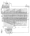
- FIG. 1 is a block diagram of a transmission/reception circuit of the ultrasonic diagnostic equipment in the first embodiment of the invention.
- a probe 1 is an ultrasonic probe comprising an array of transducer elements 2-1 to 2-32.
- the transducer elements 2-1 to 2-32 are actuators/sensors for transmitting and receiving ultrasonic waves.
- High voltage switches (HV-SW) 3-1 to 3-32 are switches for selecting transducer elements corresponding to an aperture to be used and applying high voltage transmission pulse.
- Pulsers 4-1 to 4-16 are transmission drive circuits for generating the high voltage transmission pulse.
- a trigger generator 5 is a means for generating a transmission trigger signal, a timing signal to output ultrasonic pulse.
- Limiters 6-1 to 6-32 are means for clipping (limit a voltage value) the high voltage transmission pulse to enter a cross point switch 7 in order to protect circuits such as the subsequent stage cross point switch 7 from the high voltage transmission pulse generated in the pulsers 4-1 to 4-8.
- the cross point switch 7 is a means for sorting and adding output signals of the limiters 6-1 to 6-32 to obtain synthetic receiver signals.
- A/D converters 8-1 to 8-8 are means for converting the analog synthetic receiver signals to digital signals.
- a beam forming device 9 is a means for delay-adding the digital converted synthetic receiver signals and adjusting directivity.
- a controller 10 is a means for performing timing control of a transmission circuit and a reception circuit of ultrasonic waves.
- Low voltage switches (LV-SW) 11-1 to 11-16 are switches for selecting receiver signals to be used from among the output signals of the limiters 6-1 to 6-32.
- the ultrasonic diagnostic equipment in the first embodiment of the invention constructed as above will be hereinafter described. It is different from conventional equipments that the high voltage switches 3-1 to 3-32 for selecting transducer elements to transmit ultrasonic pulse are separated from the low voltage switches 11-1 to 11-16 for selecting transducer elements which has received ultrasonic echo.
- the circuit for transmitting ultrasonic pulse inputs into given four of the high voltage switches 3-1 to 3-32 are conducted by a given one of the pulsers 4-1 to 4-8, and a distribution circuit of 1:4 is constructed. Therefore, when the ultrasonic pulse is transmitted, 32 pieces of the transducer elements 2-1 to 2-32 can be driven by the eight pulsers, and therefore, linear scanning is enabled.
- every two outputs of the low voltage switches 11-1 to 11-16 are integrated into one respectively, and a multiplexer of 2:1 is constructed.
- the trigger generator 5 generates a transmission trigger signal, a timing signal to output ultrasonic pulse.
- the pulsers 4-1 to 4-8 generate transmission pulse.
- high voltage transmission pulse is applied to only transducer elements to be driven among the transducer elements 2-1 to 2-32 arrayed in the probe 1.
- a position and a width of an aperture of the probe 1 are determined.
- the selected eight transducer elements of the probe 1 transmit ultrasonic waves to an examination object.
- the limiters 6-1 to 6-32 clips the high voltage transmission pulse to enter the cross point switch 7.
- Reflected ultrasonic waves from the examination object are received at the transducer elements 2-1 to 2-32.
- the receiver signals pass 16 pieces selected from among the low voltage switches 11-1 to 11-32, and enter the cross point switch 7.
- the receiver signals are sorted and added, and then changed into eight synthetic receiver signals.
- the synthetic receiver signals are converted to digital signals.
- the digital converted receiver signals are delay-added, and directivity is adjusted.
- the resultant output signal is converted to an image signal in an unshown circuit, and displayed.
- the controller 10 performs timing control of the transmission circuit and the reception circuit of the ultrasonic waves.
- the ultrasonic diagnostic equipment has a construction, wherein the switches 3-1 to 3-32 for selecting transducer elements to transmit ultrasonic waves are separated from the switches 11-1 to 11-32 for selecting the vibratos 2-1 to 2-32 to receive the ultrasonic waves. Therefore, the number of the transmission drive circuits (pulsers) can be reduced, and manufacturing cost can be reduced while performance is maintained.
- the ultrasonic diagnostic equipment of the second embodiment of the invention is an ultrasonic diagnostic equipment, wherein a connection pattern of high voltage switches for selecting transducer elements to transmit ultrasonic waves is changed at the controller 10 into a connection pattern wherein an aperture wider than a minimum aperture determined by the number of transmission drive circuits can be obtained, and the high voltage switches are turned ON/OFF at the controller 10.
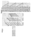
- FIG. 2 is an explanation drawing of a connection method of the high voltage switches of a transmission circuit of the ultrasonic diagnostic equipment in the second embodiment of the invention.
- the transducer elements 2-1 to 2-32 are actuators/sensors for transmitting or receiving ultrasonic waves.
- the high voltage switches (HV-SW) 3-1 to 3-32 are switches for selecting transducer elements corresponding to an aperture to be used and applying high voltage transmission pulse.
- a general construction of the ultrasonic diagnostic equipment in the second embodiment is similar to of the ultrasonic diagnostic equipment in the first embodiment shown in Fig. 1.
- Pattern P1 is a regular switch connection pattern. ⁇ mark indicates a position of a switch to be turned ON.
- An aperture is a minimum aperture (8), which is determined by the number of the transmission drive circuits (8).
- PA1 of Pattern P1 a center of the aperture becomes Aperture position #1.
- PA2 of Pattern P1 a center of the aperture becomes Aperture position #2.
- PA3 of Pattern P1 a center of the aperture becomes Aperture position #3.
- PA4 of Pattern P1 a center of the aperture becomes Aperture position #4.
- a width of an aperture becomes 12.
- a center of the aperture becomes Aperture position #1.
- a center of the aperture becomes Aperture position #2.
- a center of the aperture becomes Aperture position #3.
- a center of the aperture becomes Aperture position #4.
- a width of an aperture becomes 16.
- a center of the aperture becomes Aperture position #1.
- a center of the aperture becomes Aperture position #2.
- a center of the aperture becomes Aperture position #3.
- a center of the aperture becomes Aperture position #4.
- an aperture wider than the minimum aperture (8) determined by the number of the transmission drive circuits (8) can be realized.
- a wider aperture is required since, for example, a channel pitch of the transducer elements of the probe 1 is narrow, the aperture can be easily widened.
- the ultrasonic diagnostic equipment has a construction, wherein the connection pattern of the high voltage switches is changed, and the high voltage switches are turned ON/OFF by the connection pattern wherein an aperture becomes wider than the minimum aperture determined by the number of the transmission drive circuits. Therefore, the number of the transmission drive circuits (pulsers) can be reduced, and an inexpensive ultrasonic diagnostic equipment can be realized while performance is maintained.
- a third embodiment of the invention is an ultrasonic diagnostic equipment, wherein an ID generator is provided in a probe, and an ID encoder is provided in an equipment body.
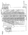
- FIG. 3 is a block diagram of a transmission/reception circuit of the ultrasonic diagnostic equipment in the third embodiment of the invention.
- an ID generator 12 is a means for generating an identification code representing a probe type.
- An ID encoder 13 is a means for converting the identification code to a control signal.
- a general construction of the ultrasonic diagnostic equipment in the third embodiment is similar to of the ultrasonic diagnostic equipment in the first embodiment shown in FIG. 1, except that the ID generator 12 is provided in the probe 1 and the ID encoder 13 is provided in the equipment body.
- the ID generator 12 When the probe 1 is connected to the equipment body, the ID generator 12 generates an identification code representing a probe type, and transmits the generated identification code to the ID encoder 13 provided in the equipment body.
- the ID encoder 13 converts the identification code to a control signal, and outputs the control signal to the controller 10.
- the probe type is read by the controller 10 by using the ID generator 12 and the ID encoder 13.
- the controller 10 controls an aperture diameter of ultrasonic beam by changing patterns of ON connection of the high voltage switches 3-1 to 3-32 according to probe types.
- the ultrasonic diagnostic equipment has a construction, wherein the ID generator is provided in the probe and the ID encoder is provided in the equipment body. Therefore, an optimum aperture diameter can be realized for each probe, a transmission circuit amount can be reduced, and an inexpensive ultrasonic diagnostic equipment can be realized while performance is maintained.
- a fourth embodiment of the invention is an ultrasonic diagnostic equipment, wherein a displayed depth input equipment is added.
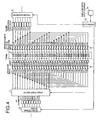
- FIG. 4 is a block diagram of a transmission/reception circuit of the ultrasonic diagnostic equipment in the forth embodiment of the invention.
- a displayed depth input equipment 14 is a means for inputting data which indicates a target displayed depth.
- a general construction of the ultrasonic diagnostic equipment in the forth embodiment is similar to of the ultrasonic diagnostic equipment in the first embodiment shown in FIG. 1, except that the displayed depth input equipment 14 is added.
- the displayed depth input equipment 14 provides the controller 10 with displayed depth information.
- the controller 10 controls an aperture diameter of ultrasonic beam by changing patterns of ON connection of the high voltage switches 3-1 to 3-32 according to displayed depths.
- the pattern of ON connection of the high voltage switches 3-1 to 3-32 is changed so that the aperture diameter of ultrasonic beam can be widened.
- the pattern of ON connection of the high voltage switches 3-1 to 3-32 is changed so that the aperture diameter of ultrasonic beam can be narrowed.
- the ultrasonic diagnostic equipment has a construction, wherein the displayed depth input equipment is added. Therefore, an optimum aperture diameter can be realized for each displayed depth, a transmission circuit amount can be reduced, and an inexpensive ultrasonic diagnostic equipment can be realized while performance is maintained.
- a fifth embodiment of the invention is an ultrasonic diagnostic equipment, wherein a display mode input equipment is added.
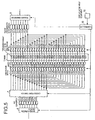
- FIG. 5 is a block diagram of a transmission/reception circuit of the ultrasonic diagnostic equipment in the fifth embodiment of the invention.
- a display mode input equipment 15 is a means for inputting data which indicates a target display mode.
- a general construction of the ultrasonic diagnostic equipment in the fifth embodiment is similar to of the ultrasonic diagnostic equipment in the first embodiment shown in FIG. 1, except that the display mode input equipment 15 is added.
- the ultrasonic diagnostic equipment in the fifth embodiment of the invention constructed as above there are various signal processing/display modes such as B mode, color Doppler mode, and pulse Doppler mode. Optimal aperture diameters vary according to the respective modes.
- the display mode input equipment 15 provides the controller 10 with display mode information.
- the controller 10 controls aperture diameters of ultrasonic beam by changing patterns of ON connection of the high voltage switches 3-1 to 3-32 according to display modes.
- the B mode is a mode, wherein a pulse transmission position or a pulse transmission direction is moved linearly, and a tomogram of a target in which an envelope curve wave form of an echo receiver signal is intensity-modulated is displayed.
- a pattern of ON connection of the high voltage switches 3-1 to 3-32 is changed so that an aperture diameter of ultrasonic beam can be widened.
- the color Doppler mode is a mode, wherein a flow rate (average Doppler deflection frequency) in each channel measured on ultrasonic beam is quantized into about eight levels, a flow coming close to the prove is converted to red color luminance information, a flow getting away from the probe is converted to blue color luminance information, and the converted information is shown on a display, while a measurement beam direction is sequentially scanned in color Doppler method which visualizes a flow rate distribution in a two-dimensional fault plane.
- a pattern of ON connection of the high voltage switches 3-1 to 3-32 is changed so that an aperture diameter of ultrasonic beam can be narrowed.
- the pulse Doppler mode is a mode for identifying and displaying a reflection part by pulsing transmitted ultrasonic wave by Doppler method.
- a pattern of ON connection of the high voltage switches 3-1 to 3-32 is changed so that an aperture diameter of ultrasonic beam can be narrowed.
- the ultrasonic diagnostic equipment has a construction, wherein the display mode input equipment is added. Therefore, an optimal aperture diameter can be realized for each display mode, a transmission circuit amount can be reduced, and an inexpensive ultrasonic diagnostic equipment can be realized while performance is maintained.
- a sixth embodiment of the invention is an ultrasonic diagnostic equipment, wherein a transmission focus depth input equipment is added.
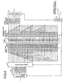
- FIG. 6 is a block diagram of a transmission/reception circuit of the ultrasonic diagnostic equipment in the sixth embodiment of the invention.
- a transmission focus depth input equipment 16 is a means for inputting data which indicates a target transmission focus depth.
- a general construction of the ultrasonic diagnostic equipment in the sixth embodiment is similar to of the ultrasonic diagnostic equipment in the first embodiment shown in FIG. 1, except that the transmission focus depth input equipment 16 is added.
- a transmission focus position can be changed even though in the case of the same displayed depth.
- Optimum aperture diameters vary according to focus depths.
- the transmission focus depth input equipment 16 inputs data which indicates a target transmission focus depth to the controller 10.
- the controller 10 controls aperture diameters of ultrasonic beam by changing patterns of ON connection of the high voltage switches 3-1 to 3-32 according to transmission focus depths.
- a pattern of ON connection of the high voltage switches 3-1 to 3-32 is changed so that an aperture diameter of ultrasonic beam can be widened.
- a pattern of ON connection of the high voltage switches 3-1 to 3-32 is changed so that an aperture diameter of ultrasonic beam can be narrowed.
- the ultrasonic diagnostic equipment has a construction, wherein the focus depth input equipment is added. Therefore, an optimal aperture diameter can be realized for each transmission focus depth, a transmission circuit amount can be reduced, and an inexpensive ultrasonic diagnostic equipment can be realized while performance is maintained.
- a seventh embodiment of the invention is an ultrasonic diagnostic equipment, wherein a center frequency input equipment is added.
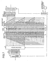
- FIG. 7 is a block diagram of a transmission/reception circuit in the seventh embodiment of the invention.
- a center frequency input equipment 17 is a means for inputting data which indicates a center frequency of transmission pulse.
- a general construction of the ultrasonic diagnostic equipment in the seventh embodiment is similar to of the ultrasonic diagnostic equipment in the first embodiment shown in FIG. 1, except that the center frequency input equipment 17 is added.
- the ultrasonic diagnostic equipment in the seventh embodiment of the invention constructed above will be hereinafter described.
- center frequency settings of transmission pulse are changed according to examined parts even the same probe is used.
- Optimum aperture diameters vary according to center frequencies.
- the center frequency input equipment 17 inputs data which indicates a center frequency of transmission pulse to the controller 10.
- the controller 10 controls aperture diameters of ultrasonic beam by changing patterns of ON connection of the high voltage switches 3-1 to 3-32 according to center frequencies of transmission pulse.
- a pattern of ON connection of the high voltage switches 3-1 to 3-32 is changed so that an aperture diameter of ultrasonic beam can be widened.
- a pattern of ON connection of the high voltage switches 3-1 to 3-32 is changed so that an aperture diameter of ultrasonic beam can be narrowed.
- the ultrasonic diagnostic equipment has a construction, wherein the center frequency input equipment is added. Therefore, an optimal aperture diameter can be realized for each center frequency, a transmission circuit amount can be reduced, and an inexpensive ultrasonic diagnostic equipment can be realized while performance is maintained.
- An eighth embodiment of the invention is an ultrasonic diagnostic equipment, wherein whether a higher resolution is prioritized or whether a wider dynamic range is prioritized is selected, and transducer elements to be used are selected according to characteristics to be prioritized.
- FIG. 8 is an explanation drawing of a connection method of high voltage switches of a transmission circuit of the ultrasonic diagnostic equipment in the eighth embodiment of the invention.
- the transducer elements 2-1 to 2-32 are actuators/sensors for transmitting or receiving ultrasonic wave.
- the high voltage switches (HV-SW) 3-1 to 3-32 are switches for selecting transducer elements corresponding to an aperture to be used and applying high voltage transmission pulse.
- a general construction of the ultrasonic diagnostic equipment in the eighth embodiment is similar to of the ultrasonic diagnostic equipment of the first embodiment shown in Fig. 1.
- a width of the aperture is 12 pieces when expressing the width by the number of transducer elements to be used, the beam shape with few side lobes can be obtained, and its dynamic range is widened.
- a center of the aperture becomes Aperture position #1.
- a center of the aperture becomes Aperture position #2.
- a center of the aperture becomes Aperture position #3.
- a center of the aperture becomes Aperture position #4.
- Pattern P4 a width of an aperture becomes 12 as well. However, the beam shape with a thin main lobe is obtained, and a resolution becomes improved.
- a center of the aperture becomes Aperture position #1.
- a center of the aperture becomes Aperture position #2.
- a center of the aperture becomes Aperture position #3.
- a center of the aperture becomes Aperture position #4.
- the ultrasonic diagnostic equipment has a construction, wherein whether a higher resolution is prioritized or whether a wider dynamic range is prioritized is selected, and transducer elements to be used are selected according to characteristics to be prioritized. Therefore, the number of the transmission drive circuits (pulsers) can be reduced, and an inexpensive ultrasonic diagnostic equipment can be realized while performance is maintained.
- a ninth embodiment of the invention is an ultrasonic diagnostic equipment, wherein a memory 18 and an adder 19 are added on the output side of a beam forming device.
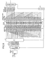
- FIG. 9 is a block diagram of a transmission/reception circuit of the ultrasonic diagnostic equipment in the ninth embodiment of the invention.
- the memory 18 is a memory for storing the first receiver signal.
- the adder 19 is a means for adding the first and the second receiver signals.
- a general construction of the ultrasonic diagnostic equipment in the ninth embodiment is similar to of the ultrasonic diagnostic equipment in the first embodiment shown in FIG. 1, except that the memory 18 and the adder 19 are added on the output side of the beam forming device.
- FIG. 10 is an operational explanation drawing of the ultrasonic diagnostic equipment in the ninth embodiment.
- An aperture using 16 transducer elements among 32 transducer elements of the probe 1 is set as Apertures K1 to K4 in FIG. 10.
- the aperture is divided into two portions, and transmission and reception of ultrasonic wave is performed two times respectively.
- In the first time as shown as 1A of Aperture K1 in FIG. 10, ultrasonic wave is transmitted by using eight vibratos at the central part of the aperture.
- In the second time as shown as 1B of Aperture K1 in FIG. 10, transmission is performed by using eight transducer elements at the both ends of the aperture.
- Receiver signal of the first time is stored in the memory 18.
- the receiver signal of the first time is outputted from the memory 18, correspondingly to a timing when a receiver signal of the second time is output from the beam forming device. These two signals are added at the adder 19.
- a center of Aperture K1 having an aperture width 16 pcs (in expressing by the number of the transducer elements to be used) becomes Aperture position K1.
- a width is 16 and a center becomes Aperture position K2.
- a width is 16 and a center becomes Aperture position K3.
- a width of the aperture is 16 pcs (in expressing by the number of transducer elements to be used) and a center becomes Aperture position K4.
- the ultrasonic diagnostic equipment has a construction, wherein the memory and the adder are added on the output side of the beam forming device. Therefore, a transmission circuit amount can be reduced, and an inexpensive ultrasonic diagnostic equipment can be realized while performance is maintained.
- a tenth embodiment of the invention is an ultrasonic diagnostic equipment, wherein high voltage switches for connecting adjacent transducer elements are added.
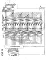
- FIG. 11 is a block diagram of a transmission/reception circuit of the ultrasonic diagnostic equipment in the tenth embodiment of the invention.
- high voltage switches 20-1 to 20-16 are switches for connecting adjacent transducer elements.
- a general construction of the ultrasonic diagnostic equipment in the tenth embodiment is similar to of the ultrasonic diagnostic equipment in the first embodiment shown in FIG. 1, except that the high voltage switches 20-1 to 20-16 for connecting adjacent transducer elements are added.
- the ultrasonic diagnostic device has a construction, wherein the high voltage switches for connecting adjacent transducer elements are added. Therefore, lowering of a sound pressure can be prevented when an aperture is widened, a transmission circuit amount can be reduced, and an inexpensive ultrasonic diagnostic equipment can be realized while performance is maintained.
- An eleventh embodiment of the invention is an ultrasonic diagnostic equipment, wherein diodes are inserted between transducer elements and high voltage switches.
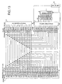
- FIG. 12 is a block diagram of a transmission/reception circuit of the ultrasonic diagnostic equipment in the eleventh embodiment of the invention.
- diodes 21-1 to 21-32 are diodes for separating receiver signals for the transducer elements 2-1 to 2-32 from each other.
- a general construction of the ultrasonic diagnostic equipment in the eleventh embodiment is similar to of the ultrasonic diagnostic equipment in the tenth embodiment shown in FIG. 11, except that the diodes 21-1 to 21-32 are connected in series between the transducer elements and the high voltage switches.
- the ultrasonic diagnostic device has a construction, wherein the diodes are inserted between the transducer elements and the high voltage switches. Therefore, deterioration of reception beam can be prevented, a transmission circuit amount can be reduced, and an inexpensive ultrasonic diagnostic equipment can be realized while performance is maintained.
- high voltage switches for selectively connecting ultrasonic transducer elements and transmission drive circuits of an ultrasonic diagnostic equipment, and low voltage switches for selecting ultrasonic transducer elements which receive ultrasonic echo are provided individually. Therefore, by respectively changing connection patterns of the high voltage switches for transmission and connection patterns of the low voltage switches for reception, the following effects can be obtained. That is, even when the number of the transmission drive circuits is reduced, linear scanning can be performed without lowering precision, and an ultrasonic diagnostic equipment having a small circuit scale can be realized at low cost.
Landscapes
- Physics & Mathematics (AREA)
- Engineering & Computer Science (AREA)
- Acoustics & Sound (AREA)
- Multimedia (AREA)
- Ultra Sonic Daignosis Equipment (AREA)
- Investigating Or Analyzing Materials By The Use Of Ultrasonic Waves (AREA)
Applications Claiming Priority (3)
| Application Number | Priority Date | Filing Date | Title |
|---|---|---|---|
| JP2002128522A JP2003319938A (ja) | 2002-04-30 | 2002-04-30 | 超音波診断装置 |
| JP2002128522 | 2002-04-30 | ||
| PCT/JP2003/004964 WO2003092505A1 (en) | 2002-04-30 | 2003-04-18 | Ultrasonograph |
Publications (2)
| Publication Number | Publication Date |
|---|---|
| EP1500370A1 true EP1500370A1 (de) | 2005-01-26 |
| EP1500370A4 EP1500370A4 (de) | 2006-08-02 |
Family
ID=29397269
Family Applications (1)
| Application Number | Title | Priority Date | Filing Date |
|---|---|---|---|
| EP03725602A Withdrawn EP1500370A4 (de) | 2002-04-30 | 2003-04-18 | Ultraschallgerät |
Country Status (5)
| Country | Link |
|---|---|
| US (1) | US7479110B2 (de) |
| EP (1) | EP1500370A4 (de) |
| JP (1) | JP2003319938A (de) |
| CN (1) | CN1649545A (de) |
| WO (1) | WO2003092505A1 (de) |
Families Citing this family (14)
| Publication number | Priority date | Publication date | Assignee | Title |
|---|---|---|---|---|
| JP3808868B2 (ja) * | 2003-12-11 | 2006-08-16 | ジーイー・メディカル・システムズ・グローバル・テクノロジー・カンパニー・エルエルシー | 超音波診断装置およびその駆動方法 |
| CN101029929B (zh) * | 2006-02-28 | 2011-02-02 | 深圳迈瑞生物医疗电子股份有限公司 | 提高超声系统前端兼容性的方法及超声前端装置 |
| JP4991355B2 (ja) * | 2007-03-14 | 2012-08-01 | 株式会社東芝 | 超音波診断装置及び超音波プローブ |
| EP2053419B1 (de) * | 2007-10-25 | 2012-10-17 | Samsung Medison Co., Ltd. | Vorrichtung und Verfahren zur Schätzung und Kompensation einer Bewegung bei der Erzeugung eines synthetischen Bildes unter Benutzung einer besonderen Abtastreihenfolge |
| WO2010055428A1 (en) * | 2008-11-11 | 2010-05-20 | Koninklijke Philips Electronics, N.V. | Configurable microbeamformer circuit for an ultrasonic diagnostic imaging system |
| US8430819B2 (en) * | 2010-05-28 | 2013-04-30 | General Electric Company | System and method for ultrasound imaging with a configurable receive aperture |
| US11109844B2 (en) * | 2015-09-25 | 2021-09-07 | Canon Medical Systems Corporation | Ultrasound diagnosis apparatus and ultrasound probe |
| US10082565B2 (en) | 2016-03-31 | 2018-09-25 | Butterfly Network, Inc. | Multilevel bipolar pulser |
| US9778348B1 (en) | 2016-03-31 | 2017-10-03 | Butterfly Network, Inc. | Symmetric receiver switch for bipolar pulser |
| JP2022504167A (ja) * | 2018-10-04 | 2022-01-13 | コーニンクレッカ フィリップス エヌ ヴェ | 超音波イメージングデバイス、システム及び方法の流体流検出 |
| US11921240B2 (en) | 2019-09-19 | 2024-03-05 | Bfly Operations, Inc. | Symmetric receiver switch for ultrasound devices |
| CN113509204A (zh) * | 2021-03-26 | 2021-10-19 | 聚融医疗科技(杭州)有限公司 | 一种用于改善乳腺超声信号的超声探头及其工作方法 |
| WO2023003886A1 (en) * | 2021-07-20 | 2023-01-26 | Bfly Operations, Inc. | Apparatuses and methods for configuring ultrasound devices |
| CN117218433B (zh) * | 2023-09-13 | 2024-08-27 | 珠海圣美生物诊断技术有限公司 | 居家多癌种检测装置和多模态融合模型构建方法及装置 |
Family Cites Families (16)
| Publication number | Priority date | Publication date | Assignee | Title |
|---|---|---|---|---|
| JPH0651038B2 (ja) * | 1984-09-21 | 1994-07-06 | 株式会社東芝 | 超音波診断装置 |
| JPH03155843A (ja) * | 1989-11-15 | 1991-07-03 | Toshiba Corp | 超音波診断装置 |
| JP3094742B2 (ja) | 1993-09-03 | 2000-10-03 | 松下電器産業株式会社 | 超音波診断装置 |
| US5617862A (en) * | 1995-05-02 | 1997-04-08 | Acuson Corporation | Method and apparatus for beamformer system with variable aperture |
| JPH09526A (ja) * | 1995-06-22 | 1997-01-07 | Toshiba Corp | 超音波診断装置 |
| US5740806A (en) * | 1996-03-29 | 1998-04-21 | Siemens Medical Systems, Inc. | Dynamic receive aperture transducer for 1.5D imaging |
| US5673699A (en) * | 1996-05-31 | 1997-10-07 | Duke University | Method and apparatus for abberation correction in the presence of a distributed aberrator |
| US6203498B1 (en) * | 1996-06-28 | 2001-03-20 | Sonosite, Inc. | Ultrasonic imaging device with integral display |
| US6030344A (en) * | 1996-12-04 | 2000-02-29 | Acuson Corporation | Methods and apparatus for ultrasound image quantification |
| JP3723663B2 (ja) * | 1997-07-15 | 2005-12-07 | フクダ電子株式会社 | 超音波診断装置 |
| US5902241A (en) * | 1997-11-24 | 1999-05-11 | General Electric Company | Large-aperture imaging using transducer array with adaptive element pitch control |
| JP3302936B2 (ja) | 1998-11-20 | 2002-07-15 | 松下電器産業株式会社 | 超音波診断装置 |
| US6174286B1 (en) * | 1998-11-25 | 2001-01-16 | Acuson Corporation | Medical diagnostic ultrasound method and system for element switching |
| US6491633B1 (en) * | 2000-03-10 | 2002-12-10 | Acuson Corporation | Medical diagnostic ultrasound system and method for contrast agent image beamformation |
| JP2001276064A (ja) * | 2000-03-31 | 2001-10-09 | Matsushita Electric Ind Co Ltd | 超音波診断装置のビームフォーマ |
| US6540677B1 (en) * | 2000-11-17 | 2003-04-01 | Bjorn A. J. Angelsen | Ultrasound transceiver system for remote operation through a minimal number of connecting wires |
-
2002
- 2002-04-30 JP JP2002128522A patent/JP2003319938A/ja active Pending
-
2003
- 2003-04-18 US US10/512,308 patent/US7479110B2/en not_active Expired - Fee Related
- 2003-04-18 CN CNA038096692A patent/CN1649545A/zh active Pending
- 2003-04-18 EP EP03725602A patent/EP1500370A4/de not_active Withdrawn
- 2003-04-18 WO PCT/JP2003/004964 patent/WO2003092505A1/ja not_active Ceased
Non-Patent Citations (2)
| Title |
|---|
| No further relevant documents disclosed * |
| See also references of WO03092505A1 * |
Also Published As
| Publication number | Publication date |
|---|---|
| US7479110B2 (en) | 2009-01-20 |
| EP1500370A4 (de) | 2006-08-02 |
| CN1649545A (zh) | 2005-08-03 |
| US20050131297A1 (en) | 2005-06-16 |
| WO2003092505A1 (en) | 2003-11-13 |
| JP2003319938A (ja) | 2003-11-11 |
Similar Documents
| Publication | Publication Date | Title |
|---|---|---|
| US7843764B2 (en) | Ultrasonic imaging apparatus | |
| US7479110B2 (en) | Ultrasonic diagnostic equipment | |
| EP2237070B1 (de) | Doppelmodus-Ultraschallwandler | |
| US5902241A (en) | Large-aperture imaging using transducer array with adaptive element pitch control | |
| JP4172841B2 (ja) | 超音波イメージング・システム、超音波イメージング・システムを動作させる方法及びマルチプレクサ・マザーボード | |
| US8485977B2 (en) | Ultrasound diagnosis apparatus | |
| US6183419B1 (en) | Multiplexed array transducers with improved far-field performance | |
| US7393324B2 (en) | Ultrasonic transmitting and receiving apparatus | |
| US6868729B2 (en) | Method of driving two-dimensional array ultrasonic probe, and ultrasonic diagnostic apparatus | |
| CN1264025C (zh) | 干涉成象的方法和装置 | |
| US4541435A (en) | Ultrasonic imaging apparatus | |
| US4344327A (en) | Electronic scanning ultrasonic diagnostic system | |
| US6821251B2 (en) | Multiplexer for connecting a multi-row ultrasound transducer array to a beamformer | |
| JP2008514335A (ja) | マイクロビーム形成を行うトランスデューサの構造 | |
| JPH0155429B2 (de) | ||
| US5511423A (en) | Ultrasonic diagnostic apparatuses and methods therefor | |
| US6716173B2 (en) | Ultrasonic imaging method and ultrasonic imaging apparatus | |
| JP2004512117A (ja) | 画像を取得するための方法、システムおよびプローブ | |
| US7481769B2 (en) | Ultrasonic diagnosing apparatus | |
| JP4365158B2 (ja) | 2次元アレイ超音波探触子 | |
| US20050203412A1 (en) | Method of controlling ultrasonic probe and ultrasonic diagnostic apparatus | |
| JP2012157553A (ja) | 超音波診断装置 | |
| US6682486B2 (en) | Ultrasonic diagnosing method and apparatus using correlative coefficient | |
| EP1598013A1 (de) | Verfahren zur bestimmung der öffnung eines ultraschallgeräts | |
| JP2005110934A (ja) | 超音波診断装置 |
Legal Events
| Date | Code | Title | Description |
|---|---|---|---|
| PUAI | Public reference made under article 153(3) epc to a published international application that has entered the european phase |
Free format text: ORIGINAL CODE: 0009012 |
|
| 17P | Request for examination filed |
Effective date: 20041021 |
|
| AK | Designated contracting states |
Kind code of ref document: A1 Designated state(s): DE FR GB |
|
| A4 | Supplementary search report drawn up and despatched |
Effective date: 20060705 |
|
| STAA | Information on the status of an ep patent application or granted ep patent |
Free format text: STATUS: THE APPLICATION HAS BEEN WITHDRAWN |
|
| 18W | Application withdrawn |
Effective date: 20060911 |