EP1500042B1 - Dispositif et procede de communication sans fil - Google Patents
Dispositif et procede de communication sans fil Download PDFInfo
- Publication number
- EP1500042B1 EP1500042B1 EP03727816A EP03727816A EP1500042B1 EP 1500042 B1 EP1500042 B1 EP 1500042B1 EP 03727816 A EP03727816 A EP 03727816A EP 03727816 A EP03727816 A EP 03727816A EP 1500042 B1 EP1500042 B1 EP 1500042B1
- Authority
- EP
- European Patent Office
- Prior art keywords
- wireless communication
- disc
- tab
- communication device
- antenna
- Prior art date
- Legal status (The legal status is an assumption and is not a legal conclusion. Google has not performed a legal analysis and makes no representation as to the accuracy of the status listed.)
- Expired - Lifetime
Links
- 238000004891 communication Methods 0.000 title claims abstract description 170
- 238000000034 method Methods 0.000 title claims description 36
- 239000004020 conductor Substances 0.000 claims description 33
- 230000008878 coupling Effects 0.000 claims description 12
- 238000010168 coupling process Methods 0.000 claims description 12
- 238000005859 coupling reaction Methods 0.000 claims description 12
- 230000004044 response Effects 0.000 claims description 9
- 230000000007 visual effect Effects 0.000 claims description 4
- 239000000758 substrate Substances 0.000 description 46
- 238000010586 diagram Methods 0.000 description 22
- 239000000463 material Substances 0.000 description 21
- 239000011888 foil Substances 0.000 description 14
- 230000008569 process Effects 0.000 description 13
- 230000005855 radiation Effects 0.000 description 13
- 238000004519 manufacturing process Methods 0.000 description 11
- 238000003860 storage Methods 0.000 description 8
- 239000003570 air Substances 0.000 description 7
- 229910052782 aluminium Inorganic materials 0.000 description 7
- XAGFODPZIPBFFR-UHFFFAOYSA-N aluminium Chemical compound [Al] XAGFODPZIPBFFR-UHFFFAOYSA-N 0.000 description 7
- 238000012546 transfer Methods 0.000 description 6
- 239000000853 adhesive Substances 0.000 description 5
- 230000001070 adhesive effect Effects 0.000 description 5
- 238000007373 indentation Methods 0.000 description 5
- 230000005404 monopole Effects 0.000 description 5
- 239000012811 non-conductive material Substances 0.000 description 5
- 238000004806 packaging method and process Methods 0.000 description 5
- 229920003023 plastic Polymers 0.000 description 5
- 239000004411 aluminium Substances 0.000 description 4
- 238000010276 construction Methods 0.000 description 4
- 230000007613 environmental effect Effects 0.000 description 4
- 239000004033 plastic Substances 0.000 description 4
- RYGMFSIKBFXOCR-UHFFFAOYSA-N Copper Chemical compound [Cu] RYGMFSIKBFXOCR-UHFFFAOYSA-N 0.000 description 3
- 238000013461 design Methods 0.000 description 3
- 239000003989 dielectric material Substances 0.000 description 3
- 230000003287 optical effect Effects 0.000 description 3
- IJGRMHOSHXDMSA-UHFFFAOYSA-N Atomic nitrogen Chemical compound N#N IJGRMHOSHXDMSA-UHFFFAOYSA-N 0.000 description 2
- QVGXLLKOCUKJST-UHFFFAOYSA-N atomic oxygen Chemical compound [O] QVGXLLKOCUKJST-UHFFFAOYSA-N 0.000 description 2
- 238000013475 authorization Methods 0.000 description 2
- 230000008901 benefit Effects 0.000 description 2
- 235000013361 beverage Nutrition 0.000 description 2
- 230000005540 biological transmission Effects 0.000 description 2
- 239000011111 cardboard Substances 0.000 description 2
- 229910052802 copper Inorganic materials 0.000 description 2
- 239000010949 copper Substances 0.000 description 2
- 239000013078 crystal Substances 0.000 description 2
- 238000005520 cutting process Methods 0.000 description 2
- 239000010437 gem Substances 0.000 description 2
- 229910001751 gemstone Inorganic materials 0.000 description 2
- 230000001939 inductive effect Effects 0.000 description 2
- 239000007788 liquid Substances 0.000 description 2
- 229910052751 metal Inorganic materials 0.000 description 2
- 239000002184 metal Substances 0.000 description 2
- 230000004048 modification Effects 0.000 description 2
- 238000012986 modification Methods 0.000 description 2
- 239000001301 oxygen Substances 0.000 description 2
- 229910052760 oxygen Inorganic materials 0.000 description 2
- 239000010453 quartz Substances 0.000 description 2
- VYPSYNLAJGMNEJ-UHFFFAOYSA-N silicon dioxide Inorganic materials O=[Si]=O VYPSYNLAJGMNEJ-UHFFFAOYSA-N 0.000 description 2
- 230000005236 sound signal Effects 0.000 description 2
- 241000894006 Bacteria Species 0.000 description 1
- 241000233866 Fungi Species 0.000 description 1
- 229920004142 LEXAN™ Polymers 0.000 description 1
- 239000004418 Lexan Substances 0.000 description 1
- 239000004743 Polypropylene Substances 0.000 description 1
- 240000004808 Saccharomyces cerevisiae Species 0.000 description 1
- 241000700605 Viruses Species 0.000 description 1
- 230000001476 alcoholic effect Effects 0.000 description 1
- 239000012080 ambient air Substances 0.000 description 1
- 239000003990 capacitor Substances 0.000 description 1
- 235000019506 cigar Nutrition 0.000 description 1
- 235000019504 cigarettes Nutrition 0.000 description 1
- 239000011889 copper foil Substances 0.000 description 1
- 239000007799 cork Substances 0.000 description 1
- 230000003247 decreasing effect Effects 0.000 description 1
- 230000009977 dual effect Effects 0.000 description 1
- 230000000694 effects Effects 0.000 description 1
- 238000004146 energy storage Methods 0.000 description 1
- 238000005516 engineering process Methods 0.000 description 1
- 239000004744 fabric Substances 0.000 description 1
- 239000012530 fluid Substances 0.000 description 1
- 230000006870 function Effects 0.000 description 1
- 230000036512 infertility Effects 0.000 description 1
- 239000004615 ingredient Substances 0.000 description 1
- 238000009413 insulation Methods 0.000 description 1
- 239000012212 insulator Substances 0.000 description 1
- 239000000696 magnetic material Substances 0.000 description 1
- 238000005259 measurement Methods 0.000 description 1
- 239000007769 metal material Substances 0.000 description 1
- 238000001465 metallisation Methods 0.000 description 1
- 150000002739 metals Chemical class 0.000 description 1
- 244000005700 microbiome Species 0.000 description 1
- 239000000203 mixture Substances 0.000 description 1
- 229910052757 nitrogen Inorganic materials 0.000 description 1
- 239000000123 paper Substances 0.000 description 1
- -1 polypropylene Polymers 0.000 description 1
- 229920001155 polypropylene Polymers 0.000 description 1
- 230000002265 prevention Effects 0.000 description 1
- 238000007639 printing Methods 0.000 description 1
- 230000001737 promoting effect Effects 0.000 description 1
- 238000000926 separation method Methods 0.000 description 1
- 229910000859 α-Fe Inorganic materials 0.000 description 1
Images


Classifications
-
- B—PERFORMING OPERATIONS; TRANSPORTING
- B65—CONVEYING; PACKING; STORING; HANDLING THIN OR FILAMENTARY MATERIAL
- B65D—CONTAINERS FOR STORAGE OR TRANSPORT OF ARTICLES OR MATERIALS, e.g. BAGS, BARRELS, BOTTLES, BOXES, CANS, CARTONS, CRATES, DRUMS, JARS, TANKS, HOPPERS, FORWARDING CONTAINERS; ACCESSORIES, CLOSURES, OR FITTINGS THEREFOR; PACKAGING ELEMENTS; PACKAGES
- B65D5/00—Rigid or semi-rigid containers of polygonal cross-section, e.g. boxes, cartons or trays, formed by folding or erecting one or more blanks made of paper
- B65D5/42—Details of containers or of foldable or erectable container blanks
- B65D5/4212—Information or decoration elements, e.g. content indicators, or for mailing
- B65D5/4233—Cards, coupons, labels or the like formed separately from the container or lid
-
- B—PERFORMING OPERATIONS; TRANSPORTING
- B65—CONVEYING; PACKING; STORING; HANDLING THIN OR FILAMENTARY MATERIAL
- B65B—MACHINES, APPARATUS OR DEVICES FOR, OR METHODS OF, PACKAGING ARTICLES OR MATERIALS; UNPACKING
- B65B15/00—Attaching articles to cards, sheets, strings, webs, or other carriers
- B65B15/04—Attaching a series of articles, e.g. small electrical components, to a continuous web
-
- B—PERFORMING OPERATIONS; TRANSPORTING
- B65—CONVEYING; PACKING; STORING; HANDLING THIN OR FILAMENTARY MATERIAL
- B65B—MACHINES, APPARATUS OR DEVICES FOR, OR METHODS OF, PACKAGING ARTICLES OR MATERIALS; UNPACKING
- B65B61/00—Auxiliary devices, not otherwise provided for, for operating on sheets, blanks, webs, binding material, containers or packages
- B65B61/20—Auxiliary devices, not otherwise provided for, for operating on sheets, blanks, webs, binding material, containers or packages for adding cards, coupons or other inserts to package contents
-
- B—PERFORMING OPERATIONS; TRANSPORTING
- B65—CONVEYING; PACKING; STORING; HANDLING THIN OR FILAMENTARY MATERIAL
- B65B—MACHINES, APPARATUS OR DEVICES FOR, OR METHODS OF, PACKAGING ARTICLES OR MATERIALS; UNPACKING
- B65B61/00—Auxiliary devices, not otherwise provided for, for operating on sheets, blanks, webs, binding material, containers or packages
- B65B61/26—Auxiliary devices, not otherwise provided for, for operating on sheets, blanks, webs, binding material, containers or packages for marking or coding completed packages
-
- B—PERFORMING OPERATIONS; TRANSPORTING
- B65—CONVEYING; PACKING; STORING; HANDLING THIN OR FILAMENTARY MATERIAL
- B65D—CONTAINERS FOR STORAGE OR TRANSPORT OF ARTICLES OR MATERIALS, e.g. BAGS, BARRELS, BOTTLES, BOXES, CANS, CARTONS, CRATES, DRUMS, JARS, TANKS, HOPPERS, FORWARDING CONTAINERS; ACCESSORIES, CLOSURES, OR FITTINGS THEREFOR; PACKAGING ELEMENTS; PACKAGES
- B65D25/00—Details of other kinds or types of rigid or semi-rigid containers
- B65D25/20—External fittings
- B65D25/205—Means for the attachment of labels, cards, coupons or the like
-
- B—PERFORMING OPERATIONS; TRANSPORTING
- B65—CONVEYING; PACKING; STORING; HANDLING THIN OR FILAMENTARY MATERIAL
- B65D—CONTAINERS FOR STORAGE OR TRANSPORT OF ARTICLES OR MATERIALS, e.g. BAGS, BARRELS, BOTTLES, BOXES, CANS, CARTONS, CRATES, DRUMS, JARS, TANKS, HOPPERS, FORWARDING CONTAINERS; ACCESSORIES, CLOSURES, OR FITTINGS THEREFOR; PACKAGING ELEMENTS; PACKAGES
- B65D33/00—Details of, or accessories for, sacks or bags
- B65D33/004—Information or decoration elements, e.g. level indicators, detachable tabs or coupons
-
- B—PERFORMING OPERATIONS; TRANSPORTING
- B65—CONVEYING; PACKING; STORING; HANDLING THIN OR FILAMENTARY MATERIAL
- B65D—CONTAINERS FOR STORAGE OR TRANSPORT OF ARTICLES OR MATERIALS, e.g. BAGS, BARRELS, BOTTLES, BOXES, CANS, CARTONS, CRATES, DRUMS, JARS, TANKS, HOPPERS, FORWARDING CONTAINERS; ACCESSORIES, CLOSURES, OR FITTINGS THEREFOR; PACKAGING ELEMENTS; PACKAGES
- B65D75/00—Packages comprising articles or materials partially or wholly enclosed in strips, sheets, blanks, tubes, or webs of flexible sheet material, e.g. in folded wrappers
- B65D75/52—Details
- B65D75/54—Cards, coupons, or other inserts or accessories
-
- G—PHYSICS
- G06—COMPUTING; CALCULATING OR COUNTING
- G06K—GRAPHICAL DATA READING; PRESENTATION OF DATA; RECORD CARRIERS; HANDLING RECORD CARRIERS
- G06K19/00—Record carriers for use with machines and with at least a part designed to carry digital markings
- G06K19/04—Record carriers for use with machines and with at least a part designed to carry digital markings characterised by the shape
- G06K19/041—Constructional details
- G06K19/042—Constructional details the record carrier having a form factor of a credit card and including a small sized disc, e.g. a CD or DVD
- G06K19/045—Constructional details the record carrier having a form factor of a credit card and including a small sized disc, e.g. a CD or DVD the record carrier being of the non-contact type, e.g. RFID, and being specially adapted for attachment to a disc, e.g. a CD or DVD
-
- G—PHYSICS
- G06—COMPUTING; CALCULATING OR COUNTING
- G06K—GRAPHICAL DATA READING; PRESENTATION OF DATA; RECORD CARRIERS; HANDLING RECORD CARRIERS
- G06K19/00—Record carriers for use with machines and with at least a part designed to carry digital markings
- G06K19/06—Record carriers for use with machines and with at least a part designed to carry digital markings characterised by the kind of the digital marking, e.g. shape, nature, code
- G06K19/067—Record carriers with conductive marks, printed circuits or semiconductor circuit elements, e.g. credit or identity cards also with resonating or responding marks without active components
- G06K19/07—Record carriers with conductive marks, printed circuits or semiconductor circuit elements, e.g. credit or identity cards also with resonating or responding marks without active components with integrated circuit chips
- G06K19/0716—Record carriers with conductive marks, printed circuits or semiconductor circuit elements, e.g. credit or identity cards also with resonating or responding marks without active components with integrated circuit chips at least one of the integrated circuit chips comprising a sensor or an interface to a sensor
-
- G—PHYSICS
- G06—COMPUTING; CALCULATING OR COUNTING
- G06K—GRAPHICAL DATA READING; PRESENTATION OF DATA; RECORD CARRIERS; HANDLING RECORD CARRIERS
- G06K19/00—Record carriers for use with machines and with at least a part designed to carry digital markings
- G06K19/06—Record carriers for use with machines and with at least a part designed to carry digital markings characterised by the kind of the digital marking, e.g. shape, nature, code
- G06K19/067—Record carriers with conductive marks, printed circuits or semiconductor circuit elements, e.g. credit or identity cards also with resonating or responding marks without active components
- G06K19/07—Record carriers with conductive marks, printed circuits or semiconductor circuit elements, e.g. credit or identity cards also with resonating or responding marks without active components with integrated circuit chips
- G06K19/0723—Record carriers with conductive marks, printed circuits or semiconductor circuit elements, e.g. credit or identity cards also with resonating or responding marks without active components with integrated circuit chips the record carrier comprising an arrangement for non-contact communication, e.g. wireless communication circuits on transponder cards, non-contact smart cards or RFIDs
- G06K19/0724—Record carriers with conductive marks, printed circuits or semiconductor circuit elements, e.g. credit or identity cards also with resonating or responding marks without active components with integrated circuit chips the record carrier comprising an arrangement for non-contact communication, e.g. wireless communication circuits on transponder cards, non-contact smart cards or RFIDs the arrangement being a circuit for communicating at a plurality of frequencies, e.g. for managing time multiplexed communication over at least two antennas of different types
-
- G—PHYSICS
- G06—COMPUTING; CALCULATING OR COUNTING
- G06K—GRAPHICAL DATA READING; PRESENTATION OF DATA; RECORD CARRIERS; HANDLING RECORD CARRIERS
- G06K19/00—Record carriers for use with machines and with at least a part designed to carry digital markings
- G06K19/06—Record carriers for use with machines and with at least a part designed to carry digital markings characterised by the kind of the digital marking, e.g. shape, nature, code
- G06K19/067—Record carriers with conductive marks, printed circuits or semiconductor circuit elements, e.g. credit or identity cards also with resonating or responding marks without active components
- G06K19/07—Record carriers with conductive marks, printed circuits or semiconductor circuit elements, e.g. credit or identity cards also with resonating or responding marks without active components with integrated circuit chips
- G06K19/077—Constructional details, e.g. mounting of circuits in the carrier
- G06K19/07749—Constructional details, e.g. mounting of circuits in the carrier the record carrier being capable of non-contact communication, e.g. constructional details of the antenna of a non-contact smart card
- G06K19/07758—Constructional details, e.g. mounting of circuits in the carrier the record carrier being capable of non-contact communication, e.g. constructional details of the antenna of a non-contact smart card arrangements for adhering the record carrier to further objects or living beings, functioning as an identification tag
-
- G—PHYSICS
- G06—COMPUTING; CALCULATING OR COUNTING
- G06K—GRAPHICAL DATA READING; PRESENTATION OF DATA; RECORD CARRIERS; HANDLING RECORD CARRIERS
- G06K19/00—Record carriers for use with machines and with at least a part designed to carry digital markings
- G06K19/06—Record carriers for use with machines and with at least a part designed to carry digital markings characterised by the kind of the digital marking, e.g. shape, nature, code
- G06K19/067—Record carriers with conductive marks, printed circuits or semiconductor circuit elements, e.g. credit or identity cards also with resonating or responding marks without active components
- G06K19/07—Record carriers with conductive marks, printed circuits or semiconductor circuit elements, e.g. credit or identity cards also with resonating or responding marks without active components with integrated circuit chips
- G06K19/077—Constructional details, e.g. mounting of circuits in the carrier
- G06K19/07749—Constructional details, e.g. mounting of circuits in the carrier the record carrier being capable of non-contact communication, e.g. constructional details of the antenna of a non-contact smart card
- G06K19/07766—Constructional details, e.g. mounting of circuits in the carrier the record carrier being capable of non-contact communication, e.g. constructional details of the antenna of a non-contact smart card comprising at least a second communication arrangement in addition to a first non-contact communication arrangement
- G06K19/07767—Constructional details, e.g. mounting of circuits in the carrier the record carrier being capable of non-contact communication, e.g. constructional details of the antenna of a non-contact smart card comprising at least a second communication arrangement in addition to a first non-contact communication arrangement the first and second communication means being two different antennas types, e.g. dipole and coil type, or two antennas of the same kind but operating at different frequencies
-
- G—PHYSICS
- G06—COMPUTING; CALCULATING OR COUNTING
- G06K—GRAPHICAL DATA READING; PRESENTATION OF DATA; RECORD CARRIERS; HANDLING RECORD CARRIERS
- G06K19/00—Record carriers for use with machines and with at least a part designed to carry digital markings
- G06K19/06—Record carriers for use with machines and with at least a part designed to carry digital markings characterised by the kind of the digital marking, e.g. shape, nature, code
- G06K19/067—Record carriers with conductive marks, printed circuits or semiconductor circuit elements, e.g. credit or identity cards also with resonating or responding marks without active components
- G06K19/07—Record carriers with conductive marks, printed circuits or semiconductor circuit elements, e.g. credit or identity cards also with resonating or responding marks without active components with integrated circuit chips
- G06K19/077—Constructional details, e.g. mounting of circuits in the carrier
- G06K19/07749—Constructional details, e.g. mounting of circuits in the carrier the record carrier being capable of non-contact communication, e.g. constructional details of the antenna of a non-contact smart card
- G06K19/07771—Constructional details, e.g. mounting of circuits in the carrier the record carrier being capable of non-contact communication, e.g. constructional details of the antenna of a non-contact smart card the record carrier comprising means for minimising adverse effects on the data communication capability of the record carrier, e.g. minimising Eddy currents induced in a proximate metal or otherwise electromagnetically interfering object
-
- G—PHYSICS
- G06—COMPUTING; CALCULATING OR COUNTING
- G06K—GRAPHICAL DATA READING; PRESENTATION OF DATA; RECORD CARRIERS; HANDLING RECORD CARRIERS
- G06K19/00—Record carriers for use with machines and with at least a part designed to carry digital markings
- G06K19/06—Record carriers for use with machines and with at least a part designed to carry digital markings characterised by the kind of the digital marking, e.g. shape, nature, code
- G06K19/067—Record carriers with conductive marks, printed circuits or semiconductor circuit elements, e.g. credit or identity cards also with resonating or responding marks without active components
- G06K19/07—Record carriers with conductive marks, printed circuits or semiconductor circuit elements, e.g. credit or identity cards also with resonating or responding marks without active components with integrated circuit chips
- G06K19/077—Constructional details, e.g. mounting of circuits in the carrier
- G06K19/07749—Constructional details, e.g. mounting of circuits in the carrier the record carrier being capable of non-contact communication, e.g. constructional details of the antenna of a non-contact smart card
- G06K19/07798—Constructional details, e.g. mounting of circuits in the carrier the record carrier being capable of non-contact communication, e.g. constructional details of the antenna of a non-contact smart card part of the antenna or the integrated circuit being adapted for rupturing or breaking, e.g. record carriers functioning as sealing devices for detecting not-authenticated opening of containers
-
- G—PHYSICS
- G11—INFORMATION STORAGE
- G11B—INFORMATION STORAGE BASED ON RELATIVE MOVEMENT BETWEEN RECORD CARRIER AND TRANSDUCER
- G11B23/00—Record carriers not specific to the method of recording or reproducing; Accessories, e.g. containers, specially adapted for co-operation with the recording or reproducing apparatus ; Intermediate mediums; Apparatus or processes specially adapted for their manufacture
- G11B23/0014—Record carriers not specific to the method of recording or reproducing; Accessories, e.g. containers, specially adapted for co-operation with the recording or reproducing apparatus ; Intermediate mediums; Apparatus or processes specially adapted for their manufacture record carriers not specifically of filamentary or web form
- G11B23/0021—Record carriers not specific to the method of recording or reproducing; Accessories, e.g. containers, specially adapted for co-operation with the recording or reproducing apparatus ; Intermediate mediums; Apparatus or processes specially adapted for their manufacture record carriers not specifically of filamentary or web form discs
- G11B23/0028—Details
- G11B23/0035—Details means incorporated in the disc, e.g. hub, to enable its guiding, loading or driving
- G11B23/0042—Details means incorporated in the disc, e.g. hub, to enable its guiding, loading or driving with provision for auxiliary features
-
- H—ELECTRICITY
- H01—ELECTRIC ELEMENTS
- H01Q—ANTENNAS, i.e. RADIO AERIALS
- H01Q1/00—Details of, or arrangements associated with, antennas
- H01Q1/12—Supports; Mounting means
- H01Q1/22—Supports; Mounting means by structural association with other equipment or articles
- H01Q1/2208—Supports; Mounting means by structural association with other equipment or articles associated with components used in interrogation type services, i.e. in systems for information exchange between an interrogator/reader and a tag/transponder, e.g. in Radio Frequency Identification [RFID] systems
- H01Q1/2225—Supports; Mounting means by structural association with other equipment or articles associated with components used in interrogation type services, i.e. in systems for information exchange between an interrogator/reader and a tag/transponder, e.g. in Radio Frequency Identification [RFID] systems used in active tags, i.e. provided with its own power source or in passive tags, i.e. deriving power from RF signal
-
- H—ELECTRICITY
- H01—ELECTRIC ELEMENTS
- H01Q—ANTENNAS, i.e. RADIO AERIALS
- H01Q1/00—Details of, or arrangements associated with, antennas
- H01Q1/12—Supports; Mounting means
- H01Q1/22—Supports; Mounting means by structural association with other equipment or articles
- H01Q1/24—Supports; Mounting means by structural association with other equipment or articles with receiving set
-
- H—ELECTRICITY
- H01—ELECTRIC ELEMENTS
- H01Q—ANTENNAS, i.e. RADIO AERIALS
- H01Q1/00—Details of, or arrangements associated with, antennas
- H01Q1/27—Adaptation for use in or on movable bodies
- H01Q1/32—Adaptation for use in or on road or rail vehicles
- H01Q1/3208—Adaptation for use in or on road or rail vehicles characterised by the application wherein the antenna is used
- H01Q1/3233—Adaptation for use in or on road or rail vehicles characterised by the application wherein the antenna is used particular used as part of a sensor or in a security system, e.g. for automotive radar, navigation systems
- H01Q1/3241—Adaptation for use in or on road or rail vehicles characterised by the application wherein the antenna is used particular used as part of a sensor or in a security system, e.g. for automotive radar, navigation systems particular used in keyless entry systems
-
- H—ELECTRICITY
- H01—ELECTRIC ELEMENTS
- H01Q—ANTENNAS, i.e. RADIO AERIALS
- H01Q13/00—Waveguide horns or mouths; Slot antennas; Leaky-waveguide antennas; Equivalent structures causing radiation along the transmission path of a guided wave
- H01Q13/10—Resonant slot antennas
-
- H—ELECTRICITY
- H01—ELECTRIC ELEMENTS
- H01Q—ANTENNAS, i.e. RADIO AERIALS
- H01Q21/00—Antenna arrays or systems
- H01Q21/28—Combinations of substantially independent non-interacting antenna units or systems
-
- H—ELECTRICITY
- H01—ELECTRIC ELEMENTS
- H01Q—ANTENNAS, i.e. RADIO AERIALS
- H01Q5/00—Arrangements for simultaneous operation of antennas on two or more different wavebands, e.g. dual-band or multi-band arrangements
- H01Q5/40—Imbricated or interleaved structures; Combined or electromagnetically coupled arrangements, e.g. comprising two or more non-connected fed radiating elements
-
- H—ELECTRICITY
- H01—ELECTRIC ELEMENTS
- H01Q—ANTENNAS, i.e. RADIO AERIALS
- H01Q9/00—Electrically-short antennas having dimensions not more than twice the operating wavelength and consisting of conductive active radiating elements
- H01Q9/04—Resonant antennas
- H01Q9/16—Resonant antennas with feed intermediate between the extremities of the antenna, e.g. centre-fed dipole
- H01Q9/28—Conical, cylindrical, cage, strip, gauze, or like elements having an extended radiating surface; Elements comprising two conical surfaces having collinear axes and adjacent apices and fed by two-conductor transmission lines
- H01Q9/285—Planar dipole
-
- H—ELECTRICITY
- H01—ELECTRIC ELEMENTS
- H01Q—ANTENNAS, i.e. RADIO AERIALS
- H01Q9/00—Electrically-short antennas having dimensions not more than twice the operating wavelength and consisting of conductive active radiating elements
- H01Q9/04—Resonant antennas
- H01Q9/30—Resonant antennas with feed to end of elongated active element, e.g. unipole
- H01Q9/40—Element having extended radiating surface
-
- B—PERFORMING OPERATIONS; TRANSPORTING
- B31—MAKING ARTICLES OF PAPER, CARDBOARD OR MATERIAL WORKED IN A MANNER ANALOGOUS TO PAPER; WORKING PAPER, CARDBOARD OR MATERIAL WORKED IN A MANNER ANALOGOUS TO PAPER
- B31B—MAKING CONTAINERS OF PAPER, CARDBOARD OR MATERIAL WORKED IN A MANNER ANALOGOUS TO PAPER
- B31B50/00—Making rigid or semi-rigid containers, e.g. boxes or cartons
- B31B50/74—Auxiliary operations
- B31B50/81—Forming or attaching accessories, e.g. opening devices, closures or tear strings
-
- B—PERFORMING OPERATIONS; TRANSPORTING
- B65—CONVEYING; PACKING; STORING; HANDLING THIN OR FILAMENTARY MATERIAL
- B65C—LABELLING OR TAGGING MACHINES, APPARATUS, OR PROCESSES
- B65C9/00—Details of labelling machines or apparatus
- B65C2009/0003—Use of RFID labels
-
- B—PERFORMING OPERATIONS; TRANSPORTING
- B65—CONVEYING; PACKING; STORING; HANDLING THIN OR FILAMENTARY MATERIAL
- B65D—CONTAINERS FOR STORAGE OR TRANSPORT OF ARTICLES OR MATERIALS, e.g. BAGS, BARRELS, BOTTLES, BOXES, CANS, CARTONS, CRATES, DRUMS, JARS, TANKS, HOPPERS, FORWARDING CONTAINERS; ACCESSORIES, CLOSURES, OR FITTINGS THEREFOR; PACKAGING ELEMENTS; PACKAGES
- B65D2203/00—Decoration means, markings, information elements, contents indicators
- B65D2203/10—Transponders
-
- G—PHYSICS
- G11—INFORMATION STORAGE
- G11B—INFORMATION STORAGE BASED ON RELATIVE MOVEMENT BETWEEN RECORD CARRIER AND TRANSDUCER
- G11B23/00—Record carriers not specific to the method of recording or reproducing; Accessories, e.g. containers, specially adapted for co-operation with the recording or reproducing apparatus ; Intermediate mediums; Apparatus or processes specially adapted for their manufacture
- G11B23/28—Indicating or preventing prior or unauthorised use, e.g. cassettes with sealing or locking means, write-protect devices for discs
- G11B23/286—Antitheft arrangements, e.g. Electronic Article Surveillance [EAS] tags
Definitions
- This application relates to wireless communication device. Such devices are described in our U.S. Patents Nos. 6,483,473 and 6,501,435 .
- One method of tracking and providing information concerning packages is to attach a wireless communication device, such as radio frequency identification (RFID) transponder or other identification device, to packages.
- RFID radio frequency identification
- the information communicated concerning the packages may include identification information, expiration dates, "born on" dates, lot numbers, manufacturing information, and the like.
- a wireless communication device may be attached to an individual package or to a container containing multiple packages.
- a pole antenna connected to the wireless communication device will not radiate properly if the wireless communication device is attached on the outside of the package.
- the pole antenna will be shielded if the wireless communication device is placed inside the package.
- wireless communication devices are also used with many other substrates.
- Each substrate has its own dielectric characteristics that typically affect the impedance matching between the wireless communication device and its antenna. Impedance matching ensures the most efficient energy transfer between an antenna and the wireless communication device.
- Discs can be any type of circular substrate, but the present invention address discs that store digital information in particular such as compact discs or mini discs.
- mini disc does not refer to the trademark used by SONY, but rather to a miniature compact disc that is optically read.
- Most compact discs and mini discs are made from a metalized outer portion and a plastic inner portion.
- Digital video discs or Digital versatile discs are made from substantially the same structure.
- This tracking may be for identification, such as in a retail outlet, computer system or jukebox (for compact-discs), theft prevention, authenticity purposes or the like as needed or desired.
- the WO00/23994 A1 discloses a smart optical storage medium.
- This optical storage medium comprises a compact disc which includes an integral information storage and communication apparatus for storing and communicating information to an external system.
- the information storage and communication apparatus comprises a circuit including a memory for storing information and a communication device in form of an antenna for communicating the information with the external system.
- a disadvantage of this storage medium is that the communication device only allows communication of information via a respective frequency.
- the storage medium has to be adapted for various applications.
- wireless communication device may also advantageous for such a wireless communication device to communicate on different frequencies so that one device can be used for various applications. For instance, an operating frequency of 2.45 GHz is used frequently outside the United States, but an operating frequency of 915 MHz is frequently used in the United States. Many companies manufacture wireless communication devices that are capable of operating at both 915 MHz and 2.45 GHz frequencies so that either frequency can be chosen for operation. However, wireless communications device applications, such as attaching wireless communication devices to packages for informative and tracking purposes, configure the device to communicate an only one frequency-- either a frequency for the United States or a frequency for use abroad. It would be advantageous to construct a wireless communication device with an antenna structure that is capable of communicating at more than one frequency. This would allow one wireless communication device to be applicable for uses in both the United States and abroad.
- the invention provides a wireless communication device for use in conjunction with a disc, such as a compact disc, mini disc or digital video disc, or comparable item.
- a disc such as a compact disc, mini disc or digital video disc, or comparable item.
- an antenna is formed with a conductive tape or the like attached to a center portion of the disc.
- the metalization of the disc coupled with the tape form a slot antenna for operation at a first frequency.
- conductive tabs may be used to couple to the slot in such a fashion that the tabs form an antenna at a second frequency.
- These conductive tabs may also serve the purpose of delimiting the length of the slot regardless of their use as a second antenna.
- a wireless communication device is shown that contains a control system, communication electronics, memory, and an antenna.
- the wireless communication device may contain a sensor to sense environmental conditions surrounding the wireless communication device.
- the wireless communication device contains one or more tabs constructed out of conductive material. The tab(s) may serve as both a pole antenna and may attach the wireless communication device to a slot, thereby forming a slot antenna.
- wireless communication device the same is a transponder that is interrogated by an interrogation reader for communication purposes.
- the wireless communication device is attached to a package that may be constructed out of a conductive material, such as foil packaging used for food or liquid.
- the tab(s) form a pole antenna to communicate in a first mode at one frequency, and the tab(s) are attached across a slot in a package to communicate in a second mode at a second frequency.
- One tab is used in one example to form a monopole type antenna, and two tabs are used in another example to form a dipole antenna.
- the tab(s) can be varied in shape and size to adjust to surfaces that vary in form.
- an asymmetrical antenna arrangement may be provided so that the impedance of the antenna is not substantially affected by the substrate to which the wireless communication device is attached.
- the asymmetrical antenna arrangement is an asymmetrical dipole antenna formed by asymmetrical tabs.
- the wireless communication device may be placed in an indentation in the substrate so that the wireless communication device does not protrude from the substrate surface.
- Asymmetrical tabs are placed on the surface of the substrate. The asymmetrical tabs are connected to the wireless communication device with feed lines to provide an asymmetrical dipole antenna.
- the asymmetrical antenna arrangement is an asymmetrical slot antenna.
- a wireless communication device placed onto a disc such as a compact disc or video disc, is used in conjunction with an interrogator to identify a disc for either promotional or security purposes.
- a customer may purchase a compact disc or video disc in a retail store. As the customer leaves the retail store, an interrogator determines the identification of the disc purchased by the customer and displays and/or plays a special message to the customer. If an interrogator detects an unpurchased disc leaving the retail store, the interrogator may indicate an alert and/or alarm condition.
- the present invention is directed to a particular wireless communication device positioned on a disc.
- this technology builds on a line of patent applications with related subject matter.
- This related subject matter is presented in full below, wherein the embodiments shown in the Figures 2 to 17 do not directly incorporate the invention but represent background art and are useful for understanding the invention, especially for the understanding of preferred embodiments of the invention as they show parts of these preferred embodiments that can be directly incorporated into embodiments incorporating the invention or can be combined with the same, with the new material described with reference to Figures 18 and 19 following.
- mini disc is a miniaturized optical disc.
- DVD includes digital video discs and digital versatile discs, the latter capable of storing computer data as well as video data.
- the prior inventions were directed to a device, system and method of attaching a wireless communication device, such as a radio frequency identification device (RFID), to a package or container to communicate information about the package or container.
- a wireless communication device such as a radio frequency identification device (RFID)
- RFID radio frequency identification device
- the package may be an individual package containing specific contents, or an individual, exterior package containing a group of additional, interior individual packages.
- the word "package” and “container” are used interchangeably herein to describe a material that houses contents, such as goods or other individual packages, and equivalent structures. The present invention should not be limited to any particular meaning or method when either "package” or “container” is used.
- the invention includes a wireless communication device 10 for electronic communication.
- Some wireless communication devices 10 have both a transmitter and receiver.
- Other wireless communication devices 10, known in the art as "transponders,” are interrogated by interrogation reader 50, whereby the transponder communicates back by altering field 58 containing interrogation signal 56.
- This description refers to the terms "transponder” and wireless communication device 10 interchangeably, and the use of the term transponder is not intended to limit the type of wireless communication device 10 applicable to the present invention.
- Wireless communication devices 10 are available that communicate at various frequencies, including UHF and VHF.
- One embodiment of the present invention uses a wireless communication device 10, also called a "transponder,” that is a passive radio-frequency device with the ability to rectify incoming radio energy and provide power to power the device for communication and operation.
- the invention is also applicable to active devices that have their own power source for communications. It should be readily understood to one of ordinary skill in the art that there are many other different types of wireless communication devices 10 that allow electronic communication and thus the present invention is not limited to any one particular type.
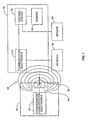
- Transponder 10 includes a control system 12 and communication electronics 14. Transponder 10 may also contain memory 18 for storage of information to be communicated to an interrogation reader 50. Alternatively, transponder 10 may store information such as an identification number or other information by using diodes, dip switches or some other like circuitry in lieu of erasable memory 18. Antenna 16 is provided to receive the interrogation signal 56 from interrogation reader 50. Antenna 16 may be either external to or internal to transponder 10. The particular type and location of antenna 16 will depend on the operating frequency of transponder 10 and the particular design desired. Transponder 10 may also be connected to sensor 20 for sensing ambient or environmental information surrounding transponder 10, package 200 containing transponder 10, or the contents of package 200.
- One example of Sensor 20 may be a quartz crystal resonator like that described in U.S. Patent No. 5,922,550 , entitled “Biosensing devices which produce diffraction Images”.
- a quartz crystal resonator detects analytes that may be present in food Analytes include, but are not limited to, microorganisms such as bacteria, yeasts, fungi and viruses.
- Antenna 16 receives signal 56 through the radiated interrogation field 58. Antenna 16 passes received signals 56 to communication electronics 14. Communication electronics 14 contain circuitry necessary to interpret signal 56 from field 58 and to further communicate the interpreted signal to control system 12.
- Control system 12 is an integrated circuit, printed circuit board, or other type of microprocessor or micro-controller electronics that controls the operations of the transponder 10. Control system 12 is connected to communication electronics 14 to communicate and receive transmissions. Control system 12 is also connected to memory 18 for storing and retrieving information. Control system 12 may further include a clock (not shown). Control system 12 determines if any actions are needed in response to the communications received from communication electronics 14.
- Figure 1 also depicts how communication is achieved with transponder 10 using an interrogation reader 50.
- Interrogation reader 50 contains interrogation communication electronics 52 and an interrogation antenna 54.
- Interrogation reader 50 communicates with the transponder 10 by emitting an electronic signal 56 modulated in a frequency by interrogation communication electronics 52 through interrogation antenna 54.
- Interrogation antenna 54 may be any type of antenna that can radiate signal 56 through a field 58 so that a compatible device, such as transponder 10, can receive such signal 56 through its own antenna 16.
- Field 58 could be electro-magnetic, magnetic, or electric.
- Signal 56 is a message containing information or a specific request for the transponder 10.
- transponder 10 When antenna 16 is in the presence of field 58 emitted by interrogation reader 50, communication electronics 14 are energized by signal 56, thereby energizing transponder 10. Transponder 10 remains energized so long as antenna 16 is in the field 58 of interrogation reader 50. Communication electronics 14 demodulates signal 56 and sends the message containing information or request to control system 12 for appropriate actions.
- the request may be for transponder 10 to communicate its identification, or information about a material or package containing transponder 10, such as date of manufacture, place of manufacture, and/or lot number.
- the message may also be a request for information regarding ambient or environmental measurements sensed by sensor 20.
- Transponder 10 is one type of wireless communication device. Other types of wireless communication devices 10 may be used which the present invention. For instance, transponder 10 may have a transmitter that can send information to interrogation reader 50 without having to alter signal 56. Transponder 10 may contain a battery to power the transmitter, or an energy storage unit that is charged by energy received from signal 56 when wireless communication device 10 is in the range of field 58. It is readily understood to one of ordinary skill in the art that there are many other types of wireless communications devices and communication techniques than those described herein, and the present invention is not limited to a particular type of device, technique or method.
- Transponder 10 may be attached on any type of device or package to identify and communicate information concerning the device or package.
- transponder 10 can be attached to a food package and may contain identification information and other information about the food contained inside the package, such as its date of manufacture, "born on" date, expiration date for sale or consumption and lot number.
- transponder 10 can be attached to a wine bottle and contain information concerning the type of wine and its ingredients or make up, the date of manufacture, and expiration dates, if applicable.
- Transponder 10 can be attached to virtually any device or package conceivable.
- FIG 2 illustrates transponder 10 attached to a food package 200.
- Antenna 16 can either be a slot antenna 16A, as illustrated in Figure 2, or a pole antenna 16B, as illustrated in Figures 3A and 3B.
- a slot 300 is provided in package 200 to provide a slot antenna 16A.
- Package 200 includes a surface 202.
- At least one tab made out of conductive material, such as a metallic material, is attached to transponder 10, and more particularly to communication electronics 14 inside transponder 10.
- Two or more tabs 100 may also be attached to transponder 10 to provide antenna 16.
- tab is used in singular and plural herein, and reference in either form is not intended to limit the invention to only one tab 100, or more than one tab 100.
- Tabs 100 are attached to slot 300 to form a slot antenna 16A.
- the word "attached” is used generically to mean either attached directly or connected to slot 300.
- the tabs 100 may either be attached on slot 300 or proximate to slot 300.
- Tabs 100 may also serve as pole antenna 16B.
- Tabs 100 may also be constructed by applying a conductive fluid (e.g. conductive ink) onto surface 202.
- a conductive fluid e.g. conductive ink
- the present invention can also be used with transponder 10 containing one tab 100 to form either slot antenna 16A or pole antenna 16B.
- One tab 100 can be used to form pole antenna 16B in the form of an antenna having monopole-like radiation pattern. If one tab 100 is used to form slot antenna 16B, tab 100 is attached to slot 300, and transponder 10 is attached, in the form of grounding, to slot 300 to form a ground plane. Using one tab 100 as a slot antenna 16B will create a monopole-like radiation pattern.
- surface 202 is constructed out of a conductive material, it may be advantageous to use tabs 100 to create a slot antenna 16A rather than a pole antenna 16B.
- conductive surfaces 202 include food foil packaging, wine bottles cork foil, jewelry, watches, cigar label foil, and alcoholic bottle foil labels. If tabs 100 are attached on a conductive surface 202 without forming a slot antenna 16A, the radiation pattern of the resulting pole antenna 16B created by tabs 100 may not be properly tuned to the operating frequency of transponder 10. Factors such as the conductivity and surface area of surface 202 affect the radiation pattern of a pole antenna 16B formed by tabs 100 when tabs 100 are attached to surface 202.
- Packages 200 vary_greatly in size,_shape, and area. It is desirable for transponder 10 and tabs 100 to be manufactured such that transponder 10 operates at a desired frequency when using tabs 100 as a pole antenna 16B, regardless of the particular characteristics of package 200.
- Packages 200 that are constructed out of conductive material, such as foil, containing transponder 10 inside the package 200 cannot use a pole antenna 16B.
- the radiation pattern of pole antenna 16B is shielded by the conductive material. Therefore, another reason for using tabs 100 to create a slot antenna 16A rather than a pole antenna 16B may be so that packages constructed out of conductive material and containing transponder 10 inside package 200 can effectively communicate desired information wirelessly.
- tabs 100 can function at the desired operating frequency as a pole antenna 16B, regardless of the characteristics of package 200. If two tabs 100 are used, the tabs 100 serve as a dipole antenna 16B. One tab 100, instead of two tabs 100, may also be used to serve as antenna 16, creating a monopole type radiation pattern as previously described above.
- a ground plane may be provided between transponder 10 and surface 202 such that communication electronics 12 is attached to surface 202 to form a ground.
- tabs 100 can serve to provide either a pole antenna 16B or slot antenna 16A depending on the package 200 and its characteristics.
- Figures 3A, 3B and 3C illustrate transponder 10 shown in Figure 2 in more detail.
- Figure 3A illustrates transponder 10 from a top view perspective.
- Tabs 100 are made out of a conductive material.
- tabs 100 may be constructed out of metals, such as aluminium or copper.
- Figure 3B illustrates transponder 100 from a side view perspective.
- Tabs 100 can either be attached directly to surface 202 or coupled to surface 202 by placing tabs 100 on an optional dielectric adhesive material 102 that is attached to surface 202. Use of adhesive material 102 may be necessary to attach the transponder 10 to surface 202.
- transponder 10 is attached an a package 200 constructed out of a conductive material without a slot 300, such that tabs 100 act as a dipole antenna 16B
- a dielectric material 102 maybe attached between the surface 202 and tabs 100 so that the radiation pattern of the dipole antenna 16B is not affected by the conductive package 200. If such a dielectric material 102 is used, tabs 100 are reactively coupled, rather than directly connected, to surface 202.
- One tab 100 instead of two tabs 100, may also be used to serve as antenna 16, creating a monopole type radiation pattern. If transponder 10, which tabs 100, is attached across a slot 300 in a conductive surface 202, a slot antenna 16A is formed for antenna 16.
- a transponder 10 may be attached to a slot antenna 16A as part of its construction, instead of using a slot 300 created in package 200 to form a slot antenna 16A.
- Figure 3 C illustrates slot 300 as a rectangular, conductive material 250 having a hollow portion cut out to form an inner, non-conductive portion 252.
- Tabs 100 are attached to non-conductive portion 252.
- Slot 300 may be constructed in any shape desired so long as slot 300 is constructed out of a conductive material 250 that contains an inner, non-conductive portion 252.
- This inner, non-conductive portion 252 can be air, formed by a cut out as illustrated in Figure 3C, or can be formed by placing a non-conductive material, such as plastic, onto or inside conductive material 250.
- the conductive material 250 may also contain an adhesive 102, so that slot 300, with transponder 10 attached, can be easily attached to package 200. It may be desirable to provide slot 300 as part of transponder 10, instead of package 200, insofar as this eliminates the requirement to create a slot 300 in package 200 as part of the construction of package 200. For example, it may be impractical or impossible to provide a slot 300 in package 200, but still desirable to attach transponder 10 to package 200 using a slot antenna 16A. As an additional advantage of this embodiment illustrated in Figure 3C, since slot 300 is provided as part of transponder 10, package 200 can be constructed out of non-conductive material.
- FIG. 4 illustrates transponder 10 with tabs 100 acting as both a pole antenna 16B and slot antenna 16A.
- a slot 300 is provided by cutting out a portion of conductive surface 202.
- the length of the tabs 100 define the operating frequency of the antenna 16 if tabs 100 are configured to act as a pole antenna 16B.
- the tabs 100 are each 1/4 in length, or 30.6 millimeters each, to form a dipole antenna 16B with a total length of 1/2 and an operating frequency of 2.45 GHz.
- tabs 100 may also serve to form a slot antenna 16A if attached across a slot 300 in a conductive surface 202.
- the slot 300 length defines the operating frequency of the slot antenna 16A.
- the slot 300 length is 1/2 or 164 millimetres so that the transponder 10 operates at a frequency of 915 MHz. More information on slot antennas 16A and their operation is described in US. Patent No. 4,975,711 , entitled "Slot antenna device for portable radiophone".
- the transponder 10 has two antenna 16 configurations that are capable of communicating at two frequencies. If transponder 10 is capable of communicating at two different frequencies, as discussed above, the pole antenna 16B and slot antenna 16A can be configured to communicate at different frequencies as well, enabling the transponder 10 to effectively communicative at both frequencies.
- This 10 arrangement provides an advantage in particular if 915 MHz is a desired frequency. 915 MHz is frequently used as an operating frequency for electronic communication in the United States, but 2.45 GHz is frequently used outside the United States. Therefore, providing transponder 10 with the capability of communicating at both 915 MHz and 2.45 GHz is advantageous so that transponder 10 can be used for applications in both 15 the United States and abroad. However, if this dual capability is not required, transponder 10 can be configured to operate solely using a pole antenna 16B or slot antenna 16A.
- Figures 5A and 5B illustrate transponder 10 attached across slots 300 of varying widths.
- the width of slot 300 affects the impedance of slot 300.
- a wider slot 300 illustrated in Figure 5A, may have higher impedance than the narrower slot 300, illustrated in Figure 5B.
- Varying the slot 300 width varies the impedance of the slot antenna 16B to maximise antenna 16 strength. It is desirable to match the impedance of slot 300 to the impedance of transponder 10.
- the slot antenna 16A has a fairly low impedance.
- Transponder 10 may comprise more than one layer, including conductive, dielectric and magnetic materials, such as ferrites, to introduce inductance, thereby aiding modification of the characteristics of surface 202 for impedance matching purposes.
- tabs 100 affect the impedance of transponder 10. As discussed above, it is desirable to match the impedance of transponder 10 and slot 300. Tabs 100 can also be varied to ensure optimal coupling to surface 202. The impedance of slot 300 may be varied for matching purposes by modifying relevant characteristics of surface 202. For example, a conductive package for food (e.g. foil) may have a surface 202 that is variable in width, dielectric or metallic characteristics. Capacitance of tabs 100 may be taken into consideration for impedance matching when attaching tabs 100 to a particular surface 202. The capacitance of tabs 100 affects the impedance of transponder 10.
- a conductive package for food e.g. foil
- Capacitance of tabs 100 may be taken into consideration for impedance matching when attaching tabs 100 to a particular surface 202.
- the capacitance of tabs 100 affects the impedance of transponder 10.
- tabs 100 The total volume of tabs 100 (surface area times thickness) affects their capacitance. Tabs 100 are similar to parallel plate capacitors in series with wireless communication device 10. The larger the volume of tabs 100, the larger their capacitance. It is therefore desirable to design and construct tabs 100 with a capacitance that is commensurate with surface 202 to match impedance of transponder 10 and slot 300 for optimal performance.
- An impedance matching network may also be used to match slot 300 impedance to transponder 10 impedance, as discussed in our International Patent Application No. WO 01/73675 , entitled "Remote Communication Using Slot Antenna”.
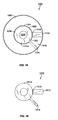
- Figure 6 illustrates two slots 300A, 300B in surface 202 that are substantially perpendicular to each other, which tabs 100 attached across the slots 300A and 300B.
- the tabs 100 are attached to slots 300A, 300B at vertical angles, but tabs 100 can also attach to slots 300A, 300B adjacent to each other.
- This structure creates a circularly polarized slot antenna 16A.
- Tabs 100 are attached to each of slots 300A and 300B.
- the length of the first slot 300A, a is slightly shorter than 1/2.
- the length of the second slot 300B, b is slightly greater than 1/2.
- the two slots 300A, 300B provide antennas 16 that can be considered resonant circuits, which their associated phase delay at the operating frequency of ⁇ 45 degrees to each other. This causes transponder 10 to receive efficiently radiation in more than one dimension and, specifically, in the form of a circular pattern so that the orientation of transponder 10 on surface 202 is somewhat irrelevant for communication.
- Figure 7 illustrates another type of package 200 containing transponder 10.
- Package 200 is configured to contain gum sticks (not shown).
- the package 200 is constructed out of a conductive material. Gum sticks are wrapped in their own individual foil wrappers and are placed inside paper non-conductive wrappings 900 contained inside package 200. Parts of the non conductive wrappings 900 touch or couple to the interior of package 200. Such attaching or coupling provides a slot antenna 300 as previously discussed, where the non-conductive wrappings provide slot 300 and the package 200 inside provides the surrounding conductive material.
- Figure 7 illustrates transponder 10 placed inside package 200. Tabs 100 are attached to slot 300, as previously described, to provide communication. Again, tabs 100 are also capable of operating as a pole antenna 16A.
- the package 200 could also be a cigarette package 200.
- the tabs 100 may be attached to a slot 300, formed by conductive material of the package 200 surrounding to an internal non-conductive portion internal to package 200, to form slot antenna 16A.
- the slot 300 may be the dielectric that forms the tear away strip that allows such packages to be opened.
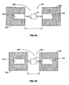
- Figures 8A and 8B illustrate particular manners in which transponder 10 is placed inside package 200.
- Figure 8A illustrates transponder 10 located inside the top of package 200 where package 200 opens and seals in a pouch-like fashion.
- Transponder 10 and tabs 100 are placed inside the top 300.
- the inside surface 202 of package 200 is a conductive material, such as a foil, including the sides of package 200 that come together when package 200 is closed and sealed.
- slot antenna 16A is not formed by cutting out a portion of surface 202, but rather by inserting a non-conductive material 302, such as a dielectric, inside package 200 at the top to form a seal 306 where the sides come together.
- a slot 300 is formed by the separation of the conductive material of inner surface 202 when the sides of package 200, are closed and sealed.
- transponder 10 may also be useful to indicate if package 200 has been opened, and, therefore, possibly contaminated. Packages 200 that contain food for consumption or medical devices and equipment requiring sterility are also possible applications. Transponder 10 is placed inside package 200 as previously discussed and illustrated in Figures 8A and 8B.
- One embodiment to detect the opening of package 200 is to provide tabs 100 constructed out of a material that reacts to ambient air. When package 200 is opened, tabs 100 become exposed to the outside air. If tabs 104 are constructed out of a material that loses its conductivity when exposed to air, transponder 10 cannot be interrogated and/or communicate as effectively since tabs 100 are attached to slot 300 to provide a slot antenna 16A for communication. Thus, lack of communication or degraded communication can be used as an indicator that package 200 has been previously opened.
- Figure 8B illustrates an embodiment where it is not only desirable to place transponder 10 inside package 200, but also to separate transponder 10 from the contents of package 200.
- a second seal 304 is provided in package 200.
- the transponder 10 is located in first seal 306 as previously described above.
- the 15 transponder 10 is still exposed to air when package 200 is opened, but transponder 10 is not contained in the same portion of package 200 where the contents of package 200 are contained.
- This embodiment may be desirable when the contents of package 200 are food or liquid for consumption, or other materials where it is not safe or desirable for transponder 10 to come in contact with the contents of package 200.
- Sensor 20 may be any type of sensor that senses elements of air in the area on the outside of package 200. Air contains oxygen, nitrogen and other gaseous elements-
- sensor 20 may be an oxygen sensor, including the sensor described in US. Patent 6,027,622 , entitled "Sensor element”.
- sensor 20 can be any type of sensor that senses an environmental factor, such as a gaseous element, that is not contained inside package 200 when sealed with transponder 10 therein.
- Figure 9 illustrates a flow chart of one embodiment of transponder 10 using sensor 20 to determine if package 200 has been opened.
- the process starts (block 400) and control system 12 receives signals from sensor 20 indicating a reading (block 402).
- the control system 12 determines if reading from sensor 20 indicates that package 200 is opened (decision 404). If package 200 is opened, control System 102 stores this event in memory 18 to communicate it the next time transponder 10 is interrogated by 10 interrogation reader 50 (block 406). If transponder 10 has transmission capability, transponder 10 may transmit the event of package 200 being open immediately.
- the process ends (block 408). Alternatively, if it is determined that the package 200 is not open (decision 404), transponder 10 takes another reading from sensor (block 402), repeating the process again.
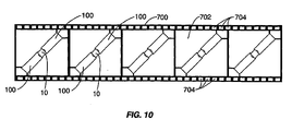
- Figure 10 illustrates an embodiment of providing transponders 10 for stamping onto packages 200 in an assembly line or other manufacturing capacity.
- a carrier 700 is provided that contains individual slides 702.
- Carrier 700 may be a film or other similar type of material.
- Transponder 10 is manufactured and placed on carrier 700 during assembly whereby each portion 702 contains one transponder 10.
- the carrier 700 is constructed out of a conductive material.
- Carrier 700 may also contain, as part of its construction, one or more conductive tabs 100. Since carrier 700 is a conductive material, tabs 100 are conductive.
- Transponder 10 is placed onto carrier during assembly and connected to tabs 100 formed in carrier 700. Later during the manufacture or assembly process, transponder 10 is placed onto packages 200.
- Carrier 700 may have perforations 704 for movement by a machine in an assembly line when mounting transponders 10 to portions 702.
- Transponder 10 attached to one or more tabs 100 formed in carrier 700, is stamped onto packages 200 in an assembly line by placing carrier 700 proximate to packages 200.
- the carrier 700 is stamped in such a manner that transponder 10, with tabs 100 attached, is placed onto packages 200.
- a stamping process places carrier 700 and a particular portion 702 in contact with package 200 so that transponder 10 is more easily attached to package 200.
- the package 200 may contain slot 300, whereby transponder 10 is stamped across the slot 300.
- Transponder 10, tabs 100, or both, may also contain an adhesive 102, as previously discussed, so that transponder 10 attaches to package 200 securely.
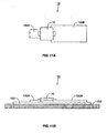
- FIG 11A illustrates a top view of transponder 10 having an asymmetrical dipole antenna 16.
- An asymmetrical dipole antenna 16 is an antenna having a first pole different in shape, including, but not necessarily limited to length, width, volume, and/or density, from the second pole.
- transponder 10 is coupled to two conductive tabs 100A, 100B.
- the first conductive tab 100A is asymmetrical with respect to the second conductive tab 100B.
- the two symmetrical tabs 100A, 100B comprises asymmetrical dipole antenna 16.
- Figure 11B illustrates a side view of one embodiment of the transponder 10 illustrated in Figure 11A.
- Tabs 100A, 100B are placed on a dielectric 102.
- Dielectric 102 acts as an insulator between tabs 100A, 100B and substrate 202.
- Dielectric 102 is a material that is substantially non-conductive. Examples of materials that may be used to form a dielectric 102 include, but are not limited to: cardboard, plastic, Lexan plastic, fabric, and polypropylene.
- substrate 202 is constructed out of a conductive material, a separate dielectric 102 is provided between substrate 202 and transponder 10 as illustrated in Figure 11B. If substrate 202 is constructed out of a non-conductive material, substrate 202 may additionally act as dielectric 102. In this case, a ground plane (not shown) may be placed on the opposite side of substrate 202, so that substrate 202, acting as a dielectric 102, is in between transponder 10 and the ground plane. Note that the ground plane may be placed on other places on substrate 202 and not necessarily on the opposite side from transponder 10.
- the shape, type, and characteristics of antenna 16 affect the impedance of transponder 10.
- the substrate 202 also affects the impedance presented to transponder 10 by antenna 16. This is especially true when a thin dielectric 102 is used, because there is less insulation between the transponder 10/antenna 16 and substrate 202.
- a thin dielectric 102 is between approximately 0.1 mm and 2.0 mm.
- the impedance of the transponder 10 should be matched to the impedance of antenna 16 as placed onto substrate 202.
- the transponder 10 may have an impedance of 15 - j60 ohms.
- antenna 16 As placed onto substrate 202, would need to have a conjugate impedance of transponder 10.
- impedance matching between transponder 10 and antenna 16 does not have to be exact to have energy transfer between transponder 10 and antenna 16 necessary for communication. Impedances between transponder 10 and antenna 16 that are substantially the same will still allow good energy transfer between antenna 16 and transponder 10.
- the transponder 10 may be used with a variety of different substrates 202.
- a thin dielectric 102 is used.
- Empirical and modeling data have shown that the operation of an asymmetric antenna 16 is substantially insensitive to the size and/or dimensions of substrate 202 when using a dielectric 102 that is relatively thin.
- Materials with poorly defined structures and/or dielectric constants, such as cardboard, can be used as dielectric 102 materials, which also serve as substrate 202. This discovery allows antenna 16 and transponder 10 impedance to be matched more easily during manufacture without having to take characteristics of substrate 202 into consideration, such as substrate 202 size, thickness, and/or dielectric constant.
- Substrate 202 does have a certain dielectric constant depending on its material of manufacture and the amount of air present in substrate 202.
- the dielectric constant is the amount of permissively of a particular material.
- antenna 16 elements such as tabs 100, do not need precise dimensional control, allowing less precise and less expensive materials and methods to be used to define such elements.
- tabs 100 may be constructed using label printing techniques and conductive ink, such as described in U.S. Patent No. 5,566,441 , entitled "Attaching an electronic circuit to a substrate".
- asymmetrical tabs 100A, 100B act as the asymmetrical antenna 16. Although the impedance of tabs 100A, 100B are substantially insensitive to substrate 202, tabs 100A, 100B may be increased or decreased in size, length, and/or width depending on variations in the thickness and dielectric constant of substrate 202 to provide optimal impedance matching to transponder 10.
- Figure 12A illustrates one modeled example of asymmetrical tabs 100A, 100B used on a substrate 202.
- Substrate 202 is a common printed circuit board (PCB) material FR4 with an approximate dielectric constant of 4.65.
- PCB printed circuit board
- Two additional tabs 101A, 101B are added to tabs 100A, 100B respectively to allow proper modeling and have no effect on results of the asymmetrical antenna 16.
- Figure 12B illustrates the predicted gain of antenna 16, which is -0.85 dBi at 915 MHz.
- Figure 12C illustrates the modeled gain of an asymmetrical antenna 16, using tabs 100A, 100B, on a substrate 202 having the same dielectric constant as FR4 without losses. The predicted gain for this model is 5.3 dBi at 915 MHz.
- tabs 100A, 100B may vary in size in different manners to provide an asymmetrical antenna 16.
- Figures 13, 14A and 14B illustrate other embodiments of asymmetrical antennas 16.
- Figure 13 illustrates an embodiment of an asymmetrical antenna 16, whereby tabs 100A, 100B are at right angles to each other.
- One tab 100A is substantially thinner than the other tab 100B.
- the performance of the asymmetrical antenna 16 illustrated in Figure 13 was found to have similar performance characteristics of the asymmetrical antenna 16 illustrated in Figure 12A.
- Figures 14A and 14B illustrate two other embodiments of an asymmetrical antenna 16.
- one tab 100B hereto represented as being thicker than tab 100A, is in the shape of a ring, and the other tab 100A is nested inside the area bounded by tab 100B.
- This asymmetrical antenna 16 is almost one-half the total length of the asymmetrical antenna 16 illustrated in Figure 12A, and may be used in applications where a shorter asymmetrical antenna 16 is desired.
- Figure 14B depicts another alternate embodiment of asymmetrical antenna 16.
- a relatively thick tab 100B is nested within tab 100A, which is arranged in the shape of a ring or loop.
- asymmetrical antenna 16 in Figure 14 B is almost one-half the total length of the asymmetrical antenna 16 illustrated in Figure 12A, and may be used in applications where a shorter asymmetrical antenna 16 is desired.
- a shorter asymmetrical antenna 16 may be advantageous for design or manufacturing reasons.
- Figure 15A illustrates another embodiment of an asymmetrical antenna dipole antenna 16, whereby substrate 202 is an aluminum can 600.
- a separate dielectric 102 is provided between transponder 10 having tabs 100A, 100B and can 600, because can 600 is constructed out of a conductive material namely aluminum (as previously discussed).
- an asymmetrical antenna 16 is created by using tab 100B that is longer in length than tab 100A.
- Figure 15B illustrates another asymmetrical antenna embodiment, again using a can 600 as substrate 202.
- Transponder 10 is placed on the underneath dome 602 of can 600.
- Two asymmetrical tabs 100A, 100B are provided to form a dipole antenna 16.
- the resultant dipole antenna 16 is asymmetrical.
- Tab 100A is shorter in length than tab 100B, and tab 100B is wider than tab 100A.
- FIG 16 illustrates another embodiment of an asymmetrical dipole antenna 16.
- transponder 10 is placed into an indentation 500 of substrate 202 so that transponder 10 will not protrude from substrate 202.
- Transponder 10 may be damaged or hit by an outside force if it protrudes from substrate 202.
- Tabs 100A,100B are provided on the surface of substrate 202 on each side of indentation 500.
- Conductive leads 502 are placed on the inside of indentation 500 and are electrically coupled to tabs 100A, 100B. Such coupling may be accomplished by direct connection, capacitive coupling or inductive coupling.
- Tabs 100A, 100B are asymmetrical to one another.
- Transponder 10 has feed lines 504 on each side that couple to conductive leads 502 to couple transponder 10 and tabs 100A, 100B together. In this manner, transponder 10 uses tabs 100A, 100B to form an asymmetrical dipole antenna 16. As illustrated, transponder 10 has not yet been positioned inside indentation 500 below the surface level of substrate 202. When properly positioned, transponder 10 does not protrude from the surface of substrate 202.
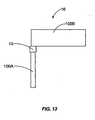
- Figure 17 illustrates another embodiment of an asymmetrical antenna 16.
- the asymmetrical antenna 16 is provided using a slot 300 to form an asymmetrical slot antenna 16.
- slot 300 length is ⁇ /4 and slot 300 width is 3.625 mm, although other lengths and widths may be used.
- Transponder 10 is placed across the slot 300 using tabs 100 to form a slot antenna 16.
- the asymmetrical nature of the slot antenna 16 is controlled by the location of the placement of tabs 100 across slot 300, and not by differences in the size, width, and/or density of tabs 100.
- Tabs 100 are placed off-center of slot 300, thereby forming an asymmetrical slot 300.
- An asymmetrical slot 300 is a slot that is split into at least two separate portions whereby each portion is of different size, width, and/or depth. If substrate 202 is constructed out of a conductive material, a separate dielectric 102 is provided between transponder 10 and substrate 202. If substrate 202 is constructed out of a non-conductive material, substrate 202 is dielectric 102 with a ground plane provided (not shown). Again, this asymmetrical antenna 16 is substantially insensitive to substrate 202 when using a thin dielectric 102, as previously discussed above.
- FIG. 17 An alternative embodiment to Figure 17 is to only couple one tab 100 to transponder 10 to provide a monopole asymmetric antenna 16. Again, tab 100 is placed off-center across slot 300. A ground plane is provided and coupled to transponder 10 so as to ground transponder 10.
- Discs may be constructed out of metalized portions that allow storage of digital information.
- Compact disc 1000 may comprise an outer metalized portion 1002 upon which data is stored as is conventional, an inner portion 1006, typically made from a transparent plastic and delimiting a central hole 1008.
- Non-conductive gap 1004 exists between outer metalized portion 1002 and inner portion 1006.
- Wireless communication device 1010 illustrated isolated from compact disc 1000 in Figure 19, may comprise a first tab 1012, a second tab 1014, and a wireless communication chip 1016.
- Wireless communication device 1010 may be either active or passive as described with reference to U.S. Patents 5,347,280 and 5,585,953 .
- Tabs 1012, 1014 serve as either a pole antenna or to provide a slot antenna for wireless communication device 1010, as discussed below.
- Tabs 1012, 1014 are a material constructed out of a conductive material, such as metal, copper, or aluminium.
- Tabs 1012, 1014 may also be in the form of a foil or tape depending on the geometry needs and/or constraints of disc 1000.
- Wireless communication chip 1016 may comprise a device from INTERMEC as used in their intellitag® labels and those devices from SCS as used in their DL100 label although other devices are certainly possible, especially in light of the present invention's suitability to both active and passive wireless communication devices 1010.
- Wireless communication chip 1016 may comprise a control system 12, memory 18, a battery, a sensor 20, and other conventional components.
- First tab 1012 capacitively couples wireless communication chip 1016 to the outer metalized portion 1002 to form a first antenna element.
- the precise dimensions of the first tab 1012 are dictated in part by the compact disc 1000 and in part by impedance matching considerations, as previously discussed above. However, also note that first tab 1012 may be directly connected to outer metalized portion 1002 to directly connect wireless communication chip 1016 to outer metalized portion 1002.
- Second tab 1014 may be an annulus and is positioned an inner portion 1006 for form a second antenna element Second tab 1014 substantially covers the annulus; however, second tab 1014 does not cover non-conductive gap 1004.
- Second tab 1014 may include a stub 1018 that extends across gap 1004 as illustrated in Figure 18.
- Wireless communication chip 1016 may likewise be positioned across gap 1004 as illustrated
- Gap 1004 may form a slot antenna operating at a first frequency for wireless communication device 1010.
- tabs 1012 and 1014 may form an asymmetric dipole antenna for operation at a second frequency.
- Exemplary frequencies are 915 MHz and 2.45 GHz.
- the present invention is also applicable to wireless communication chip 1016 only being coupled to one tab forming a monopole antenna operating at a second frequency.
- wireless communication chip 1016 with respect to stub 1018 allows the slot antenna to be formed as an asymmetric slot antenna with first portion 1020 extending from stub 1018 to wireless communication chip 1016 and a second portion 1022 comprising the other are between stub 1018 and wireless communication chip 1016.
- stub 1018 is dictated by impedance matching concerns and the desire for second tab 1014 to act as an antenna element at the second frequency. For example, while not shown, it is possible to position stub 1018 opposite wireless communication chip 1016 so that the slot antenna is not an asymmetrical slot antenna, but rather a normal-symmetric dipole slot antenna.
- stub 1018 is four (4) mm wide and extends the radius of compact disc 1000.
- first tab 1012 may be ten (10) mm wide and extend the radius of compact disc 1000.
- An arc of thirty-seven degrees separates stub 1018 from first tab 1012.
- copper foil is specifically contemplated as being a useful conductor for the construction of first tab 1012 and second tab 1014, other conductive materials such as aluminum are also possible.
- wireless communication device 1010 may have a variety of useful applications.
- wireless communication device 1010 may provide identification so that disc 1000 cannot be taken from a retail store without authorization and/or having been purchased.
- Interrogation reader 50 may be placed near exit locations in a retail store that sells discs 1000, such as a retailer of compact-discs.
- the flowchart illustrated in Figure 20 discusses the process for detecting the unauthorized removal of disc 1000 having wireless communication device 1010 attached.
- interrogation reader 50 sends out interrogation signal 56 (block 1052) to determine if wireless communication device 1010 is in range of signal 56 (decision 1054). If there is no detected wireless communication device 1010 in the range of interrogation reader 50, interrogation reader 50 continues to send out interrogation signal 56 (block 1052). If interrogation reader 50 detects wireless communication device 1010 (decision 1054), interrogation reader 50 determines if disc 1000 was legally purchased (decision 1056). If yes, the process start over by interrogation reader 50 sending out interrogation signal 56 for subsequent discs 1000 (block 1052). If no, interrogation reader 50 causes an alert condition (block 1058), and the process ends (block 1060).
- Interrogation reader 50 One way for interrogation reader to determine if disc 1000 was legally purchased or removed from a location with authorization is to interrogate discs 1000 at exit locations or other desired areas in a store. Interrogation readers 50 may also be located at points of purchase so that interrogation reader 50 can mark memory 18 in wireless communication device 1010 to indicate a legal purchase. Interrogation reader 50, located around exits or other desired locations of store, may then interrogate memory 18 of wireless communication device 1010 to determine if disc 1000 was previously purchased or authorized for removal.
- An alert condition may include an audio and/or visual message or signal.
- an audio signal may include a siren, alarm, or the like.
- Such audio signal may be public, or private whereby only certain personnel, such as security personnel, are alerted of the unauthorized removal of disc 1000 from the retail store.
- Alert conditions may also include a visual signal, both public and/or private as well.
- Wireless communication device 1010 on disc 1000 may also cause an interrogation reader 50 to perform a trigger event in response to identification of disc 1000.
- the identification of disc 1000 may be stored in memory 18 of wireless communication device 1010 in the form of a text or other message.
- a visual message may be desirable to display a visual message to a customer as the customer leaves a retail store with a newly purchased disc 1000.
- a video display linked to an interrogation reader 50, may display the artist or musical group thanking the customer for his purchase as customer leaves the store.
- Interrogation reader 50 determines the identification of disc 1000, and causes a trigger event to occur in response thereto.
- the trigger event may be any type of communication signal, and may be an audio message or combination of video and audio.
- the trigger event may also be a coupon issued to the customer for a future purchase. For instance if the customer purchases a disc 1000 containing jazz music style, interrogation reader 50, through associated with a coupon dispensing station, may issue coupons for other jazz music discs 1000 of the same artist or musical group, or discs 1000 for other jazz artists or musical groups.
- Figure 21 illustrates an interrogation reader 50 that performs a trigger event in response to a disc 1000 identification.
- the process starts (block 1080), and interrogation reader 50 sends out interrogation signal 56 (block 1082). If interrogation reader 50 does not detect a disc 1000 in range of interrogation signal 56 (decision 1084), interrogation reader 50 continues to send out interrogation signal (block 1082). If interrogation reader 50 detects disc 1000 (decision 1084), interrogation reader determines the identification of disc 1000 (block 1086) and performs the appropriate trigger event in response thereto (block 1088) before the process ends (block 1090).
- the trigger event may be an event that is external to interrogation reader 50, whereby interrogation reader 50 is coupled to an external device to perform such event. For example, such external device may be a video player that plays when a signal is received from interrogation reader 50.
- compact disc 1000 has been discussed in particular, other types of discs, including, but not limited to mini discs, DVDs, and the like are also equally suitable for use with the present invention. This is especially true in light of the uniformity of inner portion 1006 of a compact disc with comparable inner portions on mini discs and DVDs. Mini discs and DVDs are specifically defined elsewhere in the present application.
- the present invention is also well suited for use with a miniature compact disc that is shaped like a business card or in other shapes.
- shaped compact discs may be found at http://www.sculptedcd.com/homel.htm and in the document entitled "Sculpted CD, CD Business Card, Admission Ticket, CD-R3" Minis," dated 1/4/01.
- the wireless communication chip 1016 and the coupling structure of the tabs 1012, 1014 may be mounted as part of the CD jewel case.
- the wireless communication chip 1016 may only be interrogated when the compact disc 1000 is inserted into the jewel case and the case is closed bringing the chip 1016 and the tabs 1012, 1014 into close proximity to the elements that act as the antenna.
- couple, coupled, or coupling is defined as either directly connecting or reactive coupling.
- Reactive coupling is defined as either capacitive or inductive coupling.
- the present invention is intended to cover what is claimed and any equivalents. The specific embodiments used herein are to aid in the understanding of the present invention, and should not be used to limit the invention in a manner narrower than the claims and their equivalents.
Claims (30)
- Disque (1000), ayant des données mémorisées sur celui-ci, couplé à un dispositif sans fil (1010), dans lequel ledit disque (1000) comporte une partie métallisée extérieure (1002), et ledit dispositif de communication sans fil (1010) comporte : une puce de communication sans fil (1016) ; une première patte (1012) connectée électriquement à la puce de communication sans fil (1016), et positionnée sur ladite partie métallisée extérieure (1002) ; une seconde patte (1014) connectée électriquement à la puce de communication sans fil (1016), et espacée de ladite partie métallisée extérieure (1002) par un espace (1004), ladite puce de communication sans fil (1016) étant positionnée entre ladite première patte (1012) et ladite seconde patte (1014) à travers l'espace (1004), la première patte (1012) et la seconde patte (1014) étant constituées d'un matériau conducteur, caractérisé en ce que
le dispositif de communication sans fil (1010) comporte en outre un adaptateur d'impédance (1018) s'étendant depuis ladite seconde patte (1014) à travers ledit espace (1004), ledit espace (1004) formant une antenne fendue fonctionnant à une première fréquence, et les pattes (1012, 1014) formant une antenne dipôle pour un fonctionnement à une seconde fréquence. - Disque (1000) selon la revendication 1, dans lequel ledit disque (1000) est un disque compact.
- Disque selon la revendication 1, dans lequel ledit disque est un minidisque.
- Disque selon la revendication 1, dans lequel ledit disque est un DVD.
- Disque selon la revendication 1, dans lequel ladite seconde patte (1014) forme un espace annulaire positionné au-dessus d'une partie intérieure (1006) du disque (1000).
- Disque selon la revendication 1, dans lequel ladite première patte (1012) est couplée de manière capacitive à ladite partie métallisée extérieure (1002).
- Disque selon la revendication 1, dans lequel ladite première patte est couplée directement à ladite partie métallisée extérieure.
- Disque selon l'une quelconque des revendications 1 à 7, dans lequel ledit dispositif de communication sans fil (1010) comporte une mémoire (18).
- Disque selon la revendication 8, dans lequel ladite mémoire (18) est opérationnelle pour mémoriser l'identification dudit disque (1000).
- Disque selon la revendication 8 ou 9, dans lequel ladite mémoire (18) est opérationnelle pour mémoriser si oui ou non ledit disque (1000) a été acheté légalement ;
- Disque selon la revendication 9, dans lequel ladite identification est un nom d'artiste ou de groupe de musique.
- Disque selon la revendication 1, dans lequel le positionnement de la puce de communication sans fil (1016) par rapport à l'adaptateur d'impédance (1018) permet à l'antenne fendue d'être formée sous la forme d'une antenne fendue asymétrique.
- Procédé de communication d'informations concernant un disque (1000), comportant les étapes consistant à :positionner un dispositif de communication sans fil (1010) sur le disque (1000) ; etinterroger le dispositif (1010) à l'aide d'un lecteur d'interrogation (1052), caractérisé en ce que le positionnement d'un dispositif de communication sans fil (1010) sur le disque (1000) comporte le couplage d'une première patte (1012) du dispositif de communication sans fil (1010) à une partie extérieure métallisée (1002) du disque (1000),positionner une seconde patte (1014) sur une partie intérieure (1006) du disque (1000), et espacée de la partie extérieure métallisée (1002) du disque (1000) par un espace (1004), la première patte (1012) et la seconde patte (1014) étant constituées d'un matériau conducteur, et formant une antenne dipôle, etpositionner une puce de communication sans fil (1016) entre ladite première patte (1012) et ladite seconde patte (1014) de telle sorte que l'espace (1004) entre ladite partie métallisée extérieure (1002) et ladite seconde patte (1014) agit comme une antenne fendue pour un fonctionnement à une première fréquence, tandis que les pattes (1012, 1014) forment une antenne dipôle pour un fonctionnement à une seconde fréquence ;dans lequel le positionnement d'une puce de communication sans fil (1016) entre lesdites première (1012) et seconde (1014) pattes, de telle sorte que l'espace (1004) entre ladite partie métallisée extérieure (1002) et ladite seconde patte (1014) agit comme une antenne fendue, comporte en outre le positionnement d'un adaptateur d'impédance (1018) à travers l'espace (1004).
- Procédé selon la revendication 13, dans lequel l'interrogation du dispositif (1010) à l'aide d'un dispositif d'interrogation (1052, 1084) comporte l'interrogation du dispositif (1010) à une fréquence telle que la première patte (1012) et la seconde patte (1014) agissent comme une antenne pour une réponse.
- Procédé selon la revendication 13 ou 14, dans lequel ladite interrogation comporte en outre la lecture d'une mémoire (1086) dans ledit dispositif de communication sans fil (1010).
- Procédé selon la revendication 15, dans lequel ladite interrogation comporte en outre la comparaison de ladite mémoire pour déterminer si ledit disque a été acheté légalement (1056).
- Procédé selon la revendication 16, dans lequel ladite interrogation comporte en outre l'identification dudit disque (1086).
- Procédé selon la revendication 17, dans lequel ladite mémoire contient le nom d'un artiste ou d'un groupe de musique.
- Procédé selon l'une quelconque des revendications 14 à 17, comportant en outre la création d'un événement déclencheur (1088) en réponse à ladite interrogation.
- Procédé selon la revendication 18, dans lequel ledit événement déclencheur est une alarme.
- Procédé selon la revendication 18, dans lequel ledit événement déclencheur est une alerte sonore.
- Procédé selon la revendication 18, dans lequel ledit événement déclencheur est une alerte visuelle.
- Procédé selon la revendication 16, comportant en outre la délivrance d'un coupon à un client en réponse à l'identification dudit disque.
- Procédé selon la revendication 12, dans lequel ledit adaptateur d'impédance (1018) est positionné à travers l'espace (1004) pour former l'antenne fendue asymétrique.
- Dispositif de communication sans fil (1010), comportant : une puce de communication sans fil (1016) ; une première patte (1012) adaptée pour un couplage à une partie métallisée extérieure (1002) d'un disque (1000), et connectée électriquement à ladite puce de communication sans fil (1016) ; et une seconde patte (1014) adaptée pour un positionnement sur une partie intérieure (1006) du disque (1000), et connectée électriquement à ladite puce de communication sans fil (1016), la première patte (1012) et la seconde patte (1014) étant constituées d'un matériau conducteur, caractérisé en ce que
ladite seconde patte (1014) est adaptée pour être espacée, par un espace (1004), de la partie métallisée extérieure (1002), de manière à former une antenne fendue entre ceux-ci fonctionnant à une première fréquence ; et la puce de communication sans fil (1016) est positionnée à travers l'espace (1004), et les pattes (1012, 1014) forment une antenne dipôle pour un fonctionnement à une seconde fréquence. - Dispositif de communication sans fil selon la revendication 25, comportant en outre un adaptateur d'impédance (1018) s'étendant depuis ladite seconde patte (1014) à travers l'espace (1004) délimité par la partie métallisée extérieure (1002) et la seconde patte (1014).
- Dispositif de communication sans fil selon la revendication 25 ou 26, dans lequel ledit dispositif de communication sans fil (1010) est dimensionné pour s'agencer sur un disque compact (1000).
- Dispositif de communication sans fil selon la revendication 25 ou 26, dans lequel ledit dispositif de communication sans fil est dimensionné pour s'agencer sur un minidisque.
- Dispositif de communication sans fil selon la revendication 25 ou 26, dans lequel ledit dispositif de communication sans fil est dimensionné pour s'agencer sur un DVD.
- Dispositif de communication sans fil selon la revendication 26, dans lequel ledit adaptateur d'impédance (1018) est positionné de manière à créer une antenne fendue asymétrique.
Applications Claiming Priority (3)
| Application Number | Priority Date | Filing Date | Title |
|---|---|---|---|
| US10/131,576 US6806842B2 (en) | 2000-07-18 | 2002-04-24 | Wireless communication device and method for discs |
| US131576 | 2002-04-24 | ||
| PCT/IB2003/002271 WO2003092173A2 (fr) | 2002-04-24 | 2003-04-24 | Dispositif et procede de communication sans fil |
Publications (2)
| Publication Number | Publication Date |
|---|---|
| EP1500042A2 EP1500042A2 (fr) | 2005-01-26 |
| EP1500042B1 true EP1500042B1 (fr) | 2007-10-31 |
Family
ID=29268736
Family Applications (1)
| Application Number | Title | Priority Date | Filing Date |
|---|---|---|---|
| EP03727816A Expired - Lifetime EP1500042B1 (fr) | 2002-04-24 | 2003-04-24 | Dispositif et procede de communication sans fil |
Country Status (7)
| Country | Link |
|---|---|
| US (2) | US6806842B2 (fr) |
| EP (1) | EP1500042B1 (fr) |
| AT (1) | ATE377223T1 (fr) |
| AU (1) | AU2003233016A1 (fr) |
| CA (1) | CA2518612A1 (fr) |
| DE (1) | DE60317185T2 (fr) |
| WO (1) | WO2003092173A2 (fr) |
Cited By (1)
| Publication number | Priority date | Publication date | Assignee | Title |
|---|---|---|---|---|
| WO2014202735A1 (fr) | 2013-06-20 | 2014-12-24 | Universitat Autònoma De Barcelona | Disque optique ayant un dispositif de communication sans fil, dispositif de communication sans fil et procédé permettant sa conception et sa fabrication |
Families Citing this family (62)
| Publication number | Priority date | Publication date | Assignee | Title |
|---|---|---|---|---|
| US7098850B2 (en) | 2000-07-18 | 2006-08-29 | King Patrick F | Grounded antenna for a wireless communication device and method |
| US6806842B2 (en) | 2000-07-18 | 2004-10-19 | Marconi Intellectual Property (Us) Inc. | Wireless communication device and method for discs |
| US6986151B2 (en) * | 2000-09-22 | 2006-01-10 | Koninklijke Philips Electronics N.V. | Information carrier, apparatus, substrate, and system |
| JP2003108961A (ja) * | 2001-09-28 | 2003-04-11 | Hitachi Ltd | 電子タグおよびその製造方法 |
| US6946963B2 (en) * | 2001-10-16 | 2005-09-20 | Spectra Research, Inc. | Secure storage disc and disc surveillance system |
| CN1653461A (zh) * | 2002-05-09 | 2005-08-10 | 凯斯特无线有限公司 | 能够通过个人装置进行电子交易的方法和系统 |
| US7227445B2 (en) * | 2002-07-31 | 2007-06-05 | Kestrel Wireless, Inc. | Wireless activation system and method |
| US8589505B2 (en) * | 2002-11-27 | 2013-11-19 | Texas Instruments Incorporated | Method and apparatus for identifying and retrieving media content |
| US20040162739A1 (en) * | 2003-02-10 | 2004-08-19 | Michael Lax | Apparatus and methods for communicating asset information |
| US7187645B2 (en) * | 2003-03-17 | 2007-03-06 | Vidco, Inc. | Secure optical information disc having a minimized metal layer |
| US6947371B2 (en) * | 2003-03-17 | 2005-09-20 | Deluxe Media Services | Secure optical information disc |
| US7443299B2 (en) * | 2003-04-25 | 2008-10-28 | Avery Dennison Corporation | Extended range RFID system |
| GB0309498D0 (en) * | 2003-04-25 | 2003-06-04 | Avery Dennison Corp | Extended range RFID system |
| CA2530368A1 (fr) * | 2003-06-23 | 2005-01-06 | Kestrel Wireless, Inc. | Procede et appareil permettant d'activer des supports optiques |
| US7061382B2 (en) * | 2003-12-12 | 2006-06-13 | Francis M. Claessens | Apparatus for electronically verifying the authenticity of contents within a container |
| US7017807B2 (en) | 2003-09-08 | 2006-03-28 | Francis M. Claessens | Apparatus and method for detecting tampering with containers and preventing counterfeiting thereof |
| US7126479B2 (en) * | 2004-08-17 | 2006-10-24 | Francis M. Claessens | Metal container closure having integral RFID tag |
| CN100583132C (zh) * | 2003-11-04 | 2010-01-20 | 艾利丹尼森公司 | 具有加强读出性的射频识别标签 |
| JP4489082B2 (ja) | 2003-12-12 | 2010-06-23 | クレセンス、フランシス・エム | 製品に対する税が支払われているか否かを電子的に判定するための装置 |
| CN1914823A (zh) * | 2004-01-27 | 2007-02-14 | 阿尔特维拉有限公司 | 诊断性无线射频识别传感器及其应用 |
| ATE414976T1 (de) * | 2004-05-17 | 2008-12-15 | Sony Dadc Austria Ag | Optischer datenträger, verfahren und vorrichtung zur herstellung eines optischen datenträgers |
| US20050288096A1 (en) * | 2004-06-23 | 2005-12-29 | Walker Digital, Llc | Methods and apparatus for facilitating a payout at a gaming device using audio / video content |
| US8597101B2 (en) * | 2004-06-23 | 2013-12-03 | Igt | Video content determinative keno game system and method |
| US20060281523A1 (en) * | 2004-06-23 | 2006-12-14 | Walker Jay S | Video content determinative keno game system and method |
| US7850518B2 (en) * | 2004-06-23 | 2010-12-14 | Walker Digital, Llc | Video content determinative Keno game system and method |
| JP4328682B2 (ja) * | 2004-07-13 | 2009-09-09 | 富士通株式会社 | 光記録媒体用の無線タグアンテナ構造および無線タグアンテナ付き光記録媒体の収納ケース |
| US20060080819A1 (en) * | 2004-09-14 | 2006-04-20 | Mcallister Clarke W | Systems and methods for deployment and recycling of RFID tags, wireless sensors, and the containers attached thereto |
| US7292147B2 (en) * | 2004-09-24 | 2007-11-06 | Microsoft Corporation | Optical disk and method of integrating a high gain RFID antenna |
| US7378971B2 (en) * | 2004-10-01 | 2008-05-27 | Hitachi America, Ltd. | Radio frequency identification tags for digital storage discs |
| US20060100983A1 (en) * | 2004-10-26 | 2006-05-11 | Paul Atkinson | Method and system for selectively controlling the utility a target |
| US7382254B2 (en) * | 2004-12-03 | 2008-06-03 | Intel Corporation | Storage medium having RFID tag and methods for using same |
| US20070194945A1 (en) * | 2004-12-07 | 2007-08-23 | Paul Atkinson | Mobile Device for Selectively Activating a Target and Method of Using Same |
| KR20070111453A (ko) * | 2004-12-07 | 2007-11-21 | 케스트럴 와이어리스 인코포레이티드 | 타깃의 유틸리티를 선택적으로 제어하는 장치 및 그 방법 |
| US20060192653A1 (en) * | 2005-02-18 | 2006-08-31 | Paul Atkinson | Device and method for selectively controlling the utility of an integrated circuit device |
| US20060208886A1 (en) * | 2005-03-01 | 2006-09-21 | Static Control Components, Inc. | Systems and methods for providing packages with RFID tags |
| US7273181B2 (en) * | 2005-07-06 | 2007-09-25 | Kestrel Wireless, Inc. | Device and method for authenticating and securing transactions using RF communication |
| WO2007008916A2 (fr) * | 2005-07-11 | 2007-01-18 | Kestrel Wireless Inc. | Circuit integre active par frequence radioelectrique et technique de neutralisation dudit circuit |
| US20070013601A1 (en) * | 2005-07-13 | 2007-01-18 | Paul Atkinson | Devices and methods for rf communication with an optical disc |
| US20070140072A1 (en) * | 2005-07-29 | 2007-06-21 | Anoop Agrawal | Electro-Optic Device and Process for Optical Media |
| WO2007047841A2 (fr) * | 2005-10-18 | 2007-04-26 | Kestrel Wireless Inc. | Circuits et procédés de renvoi de confirmation d'activation |
| JP4693638B2 (ja) * | 2005-11-16 | 2011-06-01 | 富士通株式会社 | Rfidタグ |
| US7802274B2 (en) * | 2005-11-21 | 2010-09-21 | General Electric Company | Optical data storage article having a physical surface modification as an anti-theft feature and a system and method for inhibiting theft of same |
| WO2007085016A2 (fr) * | 2006-01-20 | 2007-07-26 | Kestrel Wireless Inc. | Support optique pourvu d'obturateurs optiques à surface réduite |
| WO2007107883A2 (fr) | 2006-03-23 | 2007-09-27 | Walker Digital, Llc | Systèmes de jeux à détermination de contenu pour jeux de keno et loteries |
| JP2007311955A (ja) * | 2006-05-17 | 2007-11-29 | Dainippon Printing Co Ltd | 背面金属層を有する非接触icタグ |
| FR2903216A1 (fr) * | 2006-06-28 | 2008-01-04 | Thomson Licensing Sa | Perfectionnement aux supports de donnees tels que les supports optiques |
| CN101473337B (zh) | 2006-06-30 | 2012-12-26 | 汤姆森特许公司 | 用于介质的射频应答器 |
| US20080046114A1 (en) * | 2006-08-15 | 2008-02-21 | White Charles A | System, packaging, and method for distributing products |
| WO2008048747A2 (fr) * | 2006-09-05 | 2008-04-24 | Kestrel Wireless Inc. | Disque équipé d'un obturateur optique |
| NL1032542C2 (nl) * | 2006-09-20 | 2008-03-21 | Knieriem B V J | Voertuigidentificatie. |
| TWI328191B (en) * | 2007-01-24 | 2010-08-01 | Ind Tech Res Inst | Method and apparatus for inspecting radio frequency identification tag |
| US8022832B2 (en) * | 2007-02-15 | 2011-09-20 | Eprovenance, Llc | Methods and systems for certifying provenance of alcoholic beverages |
| US7768407B2 (en) | 2007-06-22 | 2010-08-03 | Avery Dennison Corporation | Foldable RFID device interposer and method |
| US7880614B2 (en) * | 2007-09-26 | 2011-02-01 | Avery Dennison Corporation | RFID interposer with impedance matching |
| US8633821B2 (en) * | 2007-12-03 | 2014-01-21 | Avery Dennison Corporation | Dual use RFID/EAS device |
| US8847764B2 (en) * | 2007-12-05 | 2014-09-30 | Avery Dennison Corporation | RFID system with distributed read structure |
| US7786868B2 (en) * | 2007-12-11 | 2010-08-31 | Avery Dennison Corporation | RFID device with multiple passive operation modes |
| AU2009249061B2 (en) * | 2008-05-20 | 2015-01-22 | Deka Products Limited Partnership | RFID system |
| TW201026573A (en) * | 2009-01-13 | 2010-07-16 | Taiwan Lamination Ind Inc | Packaging material having radio frequency identification capability and its bag body structure thereof |
| US9653789B2 (en) * | 2010-04-06 | 2017-05-16 | Airwire Technologies | Antenna having planar conducting elements, one of which has a slot |
| US8717173B2 (en) * | 2010-10-13 | 2014-05-06 | Mary L. Jones | Digital disc alarm |
| US9117354B2 (en) * | 2011-03-04 | 2015-08-25 | International Business Machines Corporation | System and method for protecting against tampering with a security device |
Family Cites Families (136)
| Publication number | Priority date | Publication date | Assignee | Title |
|---|---|---|---|---|
| BE472157A (fr) | 1945-08-13 | |||
| US4054886A (en) | 1974-11-16 | 1977-10-18 | Licentia Patent-Verwaltungs-G.M.B.H. | Transmitting/receiving antenna having mirror symmetry and defined polarizations |
| US3972049A (en) | 1975-04-24 | 1976-07-27 | The United States Of America As Represented By The Secretary Of The Navy | Asymmetrically fed electric microstrip dipole antenna |
| US4117489A (en) | 1975-04-24 | 1978-09-26 | The United States Of America As Represented By The Secretary Of The Navy | Corner fed electric microstrip dipole antenna |
| US4278186A (en) | 1978-09-08 | 1981-07-14 | Williamson Robert D | Method and apparatus for beverage dispensing control and quantity monitoring |
| US4410890A (en) | 1981-05-06 | 1983-10-18 | The United States Of America As Represented By The Field Operations Bureau Of The Fcc | VHF Directional receiver |
| DE3143208C2 (de) | 1981-10-30 | 1984-07-05 | Max-E. Dipl.-Ing. 7320 Göppingen Reeb | Identifizierungsanordnung in Form eines an einem Gegenstand anbringbaren etikettartigen Streifens und Verfahren zu deren Herstellung |
| US4530483A (en) | 1982-09-30 | 1985-07-23 | Ancra Corporation | Side guide for cargo loading system |
| DE3247425A1 (de) | 1982-12-22 | 1987-01-02 | Licentia Gmbh | Gedruckte dipol-antenne in streifenleitungstechnik |
| SE8304483L (sv) | 1983-08-18 | 1985-02-19 | Sven Bachler | Navigeringssystem |
| US4575725A (en) | 1983-08-29 | 1986-03-11 | Allied Corporation | Double tuned, coupled microstrip antenna |
| US4545761A (en) | 1984-12-10 | 1985-10-08 | At&T Technologies, Inc. | Method and apparatus for securing articles in place on a substrate |
| US4670757A (en) | 1985-04-26 | 1987-06-02 | Eaton Corporation | Bistatic object location method |
| US4673923A (en) | 1986-05-19 | 1987-06-16 | Checkpoint Systems, Inc. | Article surveillance using reactivatable resonant tags |
| US4678425A (en) | 1986-08-27 | 1987-07-07 | Cincinnati Milacron Inc. | Resilient skirted spindle nose and pallet with reciprocatable spindle combined therewith |
| JPH0623054Y2 (ja) | 1987-10-07 | 1994-06-15 | 日本板硝子株式会社 | 自動車用アンテナ装置 |
| US4850020A (en) | 1987-11-05 | 1989-07-18 | Kahn Leonard R | Asymmetrical sideband AM stereo transmission |
| US4987421A (en) | 1988-06-09 | 1991-01-22 | Mitsubishi Denki Kabushiki Kaisha | Microstrip antenna |
| US4916457A (en) | 1988-06-13 | 1990-04-10 | Teledyne Industries, Inc. | Printed-circuit crossed-slot antenna |
| KR920002439B1 (ko) | 1988-08-31 | 1992-03-24 | 삼성전자 주식회사 | 휴대용 무선전화기의 슬로트 안테나 장치 |
| EP0394489B1 (fr) | 1988-10-19 | 1996-03-06 | Toyo Communication Equipment Co. Ltd. | Reseau d'antennes et organes d'alimentation pour ce reseau |
| US4947181A (en) | 1988-12-19 | 1990-08-07 | Raytheon Company | Asymmetrical biconical horn antenna |
| JPH02230584A (ja) * | 1989-03-02 | 1990-09-12 | Seiko Epson Corp | コンパクトディスク |
| US5006857A (en) | 1989-08-09 | 1991-04-09 | The Boeing Company | Asymmetrical triangular patch antenna element |
| US5073971A (en) | 1989-09-05 | 1991-12-17 | Motorola, Inc. | Cellular radiotelephone communications system |
| US4967184A (en) | 1989-09-19 | 1990-10-30 | Eastman Kodak Company | Computer disk with security protection |
| JPH03196704A (ja) | 1989-12-26 | 1991-08-28 | Mazda Motor Corp | 車両のアンテナ装置 |
| US5155493A (en) | 1990-08-28 | 1992-10-13 | The United States Of America As Represented By The Secretary Of The Air Force | Tape type microstrip patch antenna |
| US5376943A (en) | 1990-09-07 | 1994-12-27 | Plessey Semiconductors Limited | Moving vehicle transponder |
| US5081446A (en) | 1990-09-24 | 1992-01-14 | Checkpoint Systems, Inc. | Security tag for compact disc storage container |
| US5216430A (en) | 1990-12-27 | 1993-06-01 | General Electric Company | Low impedance printed circuit radiating element |
| US5123541A (en) | 1991-03-26 | 1992-06-23 | Penda Corporation | Modular shipping container and clip for assembling components thereof |
| US5187489A (en) | 1991-08-26 | 1993-02-16 | Hughes Aircraft Company | Asymmetrically flared notch radiator |
| US5508706A (en) | 1991-09-30 | 1996-04-16 | Trw Inc. | Radar signal processor |
| US5512901A (en) | 1991-09-30 | 1996-04-30 | Trw Inc. | Built-in radiation structure for a millimeter wave radar sensor |
| US5315303A (en) | 1991-09-30 | 1994-05-24 | Trw Inc. | Compact, flexible and integrated millimeter wave radar sensor |
| US5382952A (en) | 1992-01-22 | 1995-01-17 | Indala Corporation | Transponder for proximity identification system |
| GB9206974D0 (en) | 1992-03-31 | 1992-05-13 | Lawson Mardon Group Uk Ltd | Improvements in or relating to bags |
| US5298894A (en) | 1992-06-17 | 1994-03-29 | Badger Meter, Inc. | Utility meter transponder/antenna assembly for underground installations |
| US5406263A (en) | 1992-07-27 | 1995-04-11 | Micron Communications, Inc. | Anti-theft method for detecting the unauthorized opening of containers and baggage |
| US5381137A (en) | 1992-10-26 | 1995-01-10 | Motorola, Inc. | RF tagging system and RF tags and method |
| FR2697801B1 (fr) | 1992-11-06 | 1994-12-30 | Allibert Equipement | Procédé pour le suivi logistique de pièces de manutention et/ou de leur contenu, ainsi que la pièce elle-même. |
| GB9226202D0 (en) | 1992-12-16 | 1993-02-10 | Univ Bradford | Improvements on or relating to portable phones |
| WO1994019874A1 (fr) | 1993-02-26 | 1994-09-01 | Motorola Inc. | Procede et appareil de blindage h.f. |
| US5892487A (en) | 1993-02-28 | 1999-04-06 | Thomson Multimedia S.A. | Antenna system |
| ZA941671B (en) | 1993-03-11 | 1994-10-12 | Csir | Attaching an electronic circuit to a substrate. |
| FR2706422B1 (fr) | 1993-06-09 | 1995-07-28 | Esor Sarl | Palette incorporant des moyens d'inscription et de lecture à distance d'informations. |
| US5347280A (en) | 1993-07-02 | 1994-09-13 | Texas Instruments Deutschland Gmbh | Frequency diversity transponder arrangement |
| US5585953A (en) | 1993-08-13 | 1996-12-17 | Gec Plessey Semiconductors, Inc. | IR/RF radio transceiver and method |
| US5461393A (en) | 1993-08-20 | 1995-10-24 | Texas Instruments Incorporated | Dual frequency cavity backed slot antenna |
| US5539414A (en) | 1993-09-02 | 1996-07-23 | Inmarsat | Folded dipole microstrip antenna |
| US5350074A (en) | 1993-10-01 | 1994-09-27 | Morgan Marshall Industries, Inc. | Pallet rack lock |
| US5430441A (en) | 1993-10-12 | 1995-07-04 | Motorola, Inc. | Transponding tag and method |
| EP0666611B1 (fr) | 1994-02-02 | 2001-07-18 | Hughes Electronics Corporation | Antenne de balayage à dipol fixé dans un réflecteur rotatif en forme de gobelet |
| GB9404775D0 (en) | 1994-03-11 | 1994-04-27 | Payne P P Ltd | Improvements in or relating to article tagging |
| JP3464277B2 (ja) | 1994-06-20 | 2003-11-05 | 株式会社東芝 | 円偏波パッチアンテナ |
| JPH0872898A (ja) | 1994-08-31 | 1996-03-19 | Sensormatic Electronics Corp | 電子式物品監視タッグ |
| US5528222A (en) | 1994-09-09 | 1996-06-18 | International Business Machines Corporation | Radio frequency circuit and memory in thin flexible package |
| US5541399A (en) | 1994-09-30 | 1996-07-30 | Palomar Technologies Corporation | RF transponder with resonant crossover antenna coil |
| US5574470A (en) | 1994-09-30 | 1996-11-12 | Palomar Technologies Corporation | Radio frequency identification transponder apparatus and method |
| JP3417083B2 (ja) | 1994-10-04 | 2003-06-16 | セイコーエプソン株式会社 | 携帯用無線機 |
| US5600333A (en) | 1995-01-26 | 1997-02-04 | Larsen Electronics, Inc. | Active repeater antenna assembly |
| US5584113A (en) | 1995-02-08 | 1996-12-17 | Hovorka; Fred D. | Method for identifying cast parts |
| US5603430A (en) | 1995-02-10 | 1997-02-18 | Dec International, Inc. | Beverage dispensing system with bottle identification mechanism |
| US5598169A (en) | 1995-03-24 | 1997-01-28 | Lucent Technologies Inc. | Detector and modulator circuits for passive microwave links |
| US6118426A (en) | 1995-07-20 | 2000-09-12 | E Ink Corporation | Transducers and indicators having printed displays |
| US5939984A (en) | 1997-12-31 | 1999-08-17 | Intermec Ip Corp. | Combination radio frequency transponder (RF Tag) and magnetic electronic article surveillance (EAS) material |
| US6243013B1 (en) | 1999-01-08 | 2001-06-05 | Intermec Ip Corp. | Cascaded DC voltages of multiple antenna RF tag front-end circuits |
| US5955048A (en) | 1995-09-27 | 1999-09-21 | Aluminum Company Of America | Process for making flash activated hydrotalcite |
| US6411213B1 (en) | 1995-10-11 | 2002-06-25 | Motorola, Inc. | Radio frequency identification tag system using tags arranged for coupling to ground |
| US6036810A (en) | 1995-10-25 | 2000-03-14 | Holat; Barry | Method of a making and applying a holographic identifier for garments |
| US5593040A (en) | 1995-12-04 | 1997-01-14 | Delco Electronics Corporation | Rotary clip for solder pallet |
| NL1001840C2 (nl) | 1995-12-07 | 1997-06-10 | Nederland Ptt | Label. |
| DE69634452T2 (de) | 1995-12-29 | 2006-05-04 | Dresser, Inc., Addison | Ausgabesystem und verfahren mit identifizierung der kunden durch radiosignale |
| JPH09260925A (ja) | 1996-03-19 | 1997-10-03 | Matsushita Electric Ind Co Ltd | アンテナ装置 |
| DE19616819A1 (de) * | 1996-04-26 | 1997-10-30 | Giesecke & Devrient Gmbh | CD mit eingebautem Chip |
| US5652838A (en) * | 1996-05-20 | 1997-07-29 | Lovett; Donna M. | Smart disc cd-rom |
| JP2876305B2 (ja) | 1996-05-20 | 1999-03-31 | 株式会社サニー・シーリング | 視覚障害者用誘導補助システムおよびその装置 |
| US5821859A (en) | 1996-06-07 | 1998-10-13 | Ibm Corporation | Concealed magnetic ID code and antitheft tag |
| JPH09330388A (ja) | 1996-06-10 | 1997-12-22 | Denso Corp | Icカード |
| JPH1065437A (ja) | 1996-08-21 | 1998-03-06 | Saitama Nippon Denki Kk | 板状逆fアンテナおよび無線装置 |
| US5892486A (en) | 1996-10-11 | 1999-04-06 | Channel Master Llc | Broad band dipole element and array |
| DE19740254A1 (de) | 1996-10-16 | 1998-04-23 | Lindenmeier Heinz | Funkantennen-Anordnung und Patchantenne auf der Fensterscheibe eines Kraftfahrzeuges |
| US5814797A (en) | 1996-11-04 | 1998-09-29 | A Rifkin Co. | Transponder system for monitoring and logging depository transactions |
| US5842555A (en) | 1996-12-16 | 1998-12-01 | Gannon; Donald N. | Automated baggage tracking system and method for use in a baggage conveyor system |
| US6052093A (en) | 1996-12-18 | 2000-04-18 | Savi Technology, Inc. | Small omni-directional, slot antenna |
| US5922550A (en) | 1996-12-18 | 1999-07-13 | Kimberly-Clark Worldwide, Inc. | Biosensing devices which produce diffraction images |
| GB9626550D0 (en) | 1996-12-20 | 1997-02-05 | Northern Telecom Ltd | A dipole antenna |
| EP0853039B1 (fr) | 1997-01-10 | 2003-04-23 | Airbus Deutschland GmbH | Dispositif pour déplacer et fixer des conteneurs et des palettes avec sièges dans un avion |
| US6097347A (en) * | 1997-01-29 | 2000-08-01 | Intermec Ip Corp. | Wire antenna with stubs to optimize impedance for connecting to a circuit |
| SE508513C2 (sv) | 1997-02-14 | 1998-10-12 | Ericsson Telefon Ab L M | Mikrostripantenn samt gruppantenn |
| US6031503A (en) | 1997-02-20 | 2000-02-29 | Raytheon Company | Polarization diverse antenna for portable communication devices |
| FR2760225B1 (fr) | 1997-02-28 | 1999-05-21 | Smurfit Socar Sa | Conditionnement en carton ondule equipe d'un moyen d'enregistrement et d'identification d'informations |
| US5862117A (en) | 1997-03-12 | 1999-01-19 | Em Microelectronic-Marin Sa | Device, in particular a compact disc, comprising a data storage medium and an integrated circuit |
| US5972152A (en) | 1997-05-16 | 1999-10-26 | Micron Communications, Inc. | Methods of fixturing flexible circuit substrates and a processing carrier, processing a flexible circuit and processing a flexible circuit substrate relative to a processing carrier |
| DE19720892C2 (de) | 1997-05-17 | 2002-08-08 | Bosch Gmbh Robert | Sensorelement |
| US6024333A (en) | 1997-06-23 | 2000-02-15 | Midwest Air Technologies, Inc. | Shelf bracket for wire shelves |
| US6075493A (en) | 1997-08-11 | 2000-06-13 | Ricoh Company, Ltd. | Tapered slot antenna |
| JP3438565B2 (ja) | 1997-08-22 | 2003-08-18 | ユニ電子工業株式会社 | 盗難防止用タグ |
| US6054961A (en) | 1997-09-08 | 2000-04-25 | Andrew Corporation | Dual band, glass mount antenna and flexible housing therefor |
| US5973600A (en) | 1997-09-11 | 1999-10-26 | Precision Dynamics Corporation | Laminated radio frequency identification device |
| GB9721033D0 (en) | 1997-10-06 | 1997-12-03 | Stewart Company The | Containers |
| US5929760A (en) | 1997-10-20 | 1999-07-27 | Escort Memory Systems | RFID conveyor antenna |
| US6329915B1 (en) | 1997-12-31 | 2001-12-11 | Intermec Ip Corp | RF Tag having high dielectric constant material |
| US5897741A (en) | 1998-02-09 | 1999-04-27 | Premark Feg L.L.C. | Apparatus for applying security tags to labels |
| GB2335081B (en) | 1998-03-05 | 2002-04-03 | Nec Technologies | Antenna for mobile telephones |
| FR2779022B1 (fr) | 1998-05-20 | 2000-07-28 | Nortel Matra Cellular | Station de base de radiocommunication |
| US6107920A (en) | 1998-06-09 | 2000-08-22 | Motorola, Inc. | Radio frequency identification tag having an article integrated antenna |
| US6018299A (en) | 1998-06-09 | 2000-01-25 | Motorola, Inc. | Radio frequency identification tag having a printed antenna and method |
| US6082030A (en) | 1998-08-06 | 2000-07-04 | Kesselring; Valarie Lyn | Beverage can identification system |
| US6008727A (en) | 1998-09-10 | 1999-12-28 | Xerox Corporation | Selectively enabled electronic tags |
| US6325199B1 (en) | 1998-10-05 | 2001-12-04 | Axis Usa, Inc. | Pallet conveyor apparatus |
| JP3252812B2 (ja) | 1998-10-05 | 2002-02-04 | 株式会社村田製作所 | 表面実装型円偏波アンテナおよびそれを用いた無線装置 |
| US6114962A (en) | 1998-10-15 | 2000-09-05 | Intermec Ip Corp. | RF tag having strain relieved stiff substrate and hydrostatic protection for a chip mounted thereto |
| WO2000023994A1 (fr) * | 1998-10-16 | 2000-04-27 | Intermec Ip Corp. | Supports optiques intelligents |
| JP2000132945A (ja) * | 1998-10-22 | 2000-05-12 | Hitachi Ltd | ディスク |
| US6100804A (en) | 1998-10-29 | 2000-08-08 | Intecmec Ip Corp. | Radio frequency identification system |
| US6073479A (en) | 1998-11-13 | 2000-06-13 | General Electric Company | Dewpoint sensor |
| FI105421B (fi) | 1999-01-05 | 2000-08-15 | Filtronic Lk Oy | Tasomainen kahden taajuuden antenni ja tasoantennilla varustettu radiolaite |
| US6239765B1 (en) | 1999-02-27 | 2001-05-29 | Rangestar Wireless, Inc. | Asymmetric dipole antenna assembly |
| US6278413B1 (en) | 1999-03-29 | 2001-08-21 | Intermec Ip Corporation | Antenna structure for wireless communications device, such as RFID tag |
| JP2000332523A (ja) | 1999-05-24 | 2000-11-30 | Hitachi Ltd | 無線タグ、その製造方法及びその配置方法 |
| DE19925127C1 (de) | 1999-06-02 | 2000-11-02 | Daimler Chrysler Ag | Antennenanordnung in Kraftfahrzeugen |
| US6249260B1 (en) | 1999-07-16 | 2001-06-19 | Comant Industries, Inc. | T-top antenna for omni-directional horizontally-polarized operation |
| US6236314B1 (en) | 1999-09-02 | 2001-05-22 | Micron Technology, Inc. | Transponder modules, RF tagging system, method of operating a transponder module and methods of tagging an object having a conductive surface |
| US6259369B1 (en) | 1999-09-30 | 2001-07-10 | Moore North America, Inc. | Low cost long distance RFID reading |
| GB2355114B (en) | 1999-09-30 | 2004-03-24 | Harada Ind | Dual-band microstrip antenna |
| WO2001037215A1 (fr) | 1999-11-18 | 2001-05-25 | Siemens Aktiengesellschaft | Support de donnees mobile comprenant un transpondeur constitue d'un element a ondes de surface avec une antenne a fente |
| FI114254B (fi) | 2000-02-24 | 2004-09-15 | Filtronic Lk Oy | Tasoantennirakenne |
| US6628237B1 (en) | 2000-03-25 | 2003-09-30 | Marconi Communications Inc. | Remote communication using slot antenna |
| JP3655844B2 (ja) | 2000-06-30 | 2005-06-02 | 松下電器産業株式会社 | レーザー加工装置及び方法 |
| US6533108B1 (en) | 2000-07-07 | 2003-03-18 | Valu Engineering, Inc. | Serpentine clip |
| US6806842B2 (en) | 2000-07-18 | 2004-10-19 | Marconi Intellectual Property (Us) Inc. | Wireless communication device and method for discs |
| AU2001270860A1 (en) | 2000-07-18 | 2002-01-30 | Marconi Corporation P.L.C. | Wireless pallet communication device and method |
| US7098850B2 (en) | 2000-07-18 | 2006-08-29 | King Patrick F | Grounded antenna for a wireless communication device and method |
| US6483473B1 (en) | 2000-07-18 | 2002-11-19 | Marconi Communications Inc. | Wireless communication device and method |
-
2002
- 2002-04-24 US US10/131,576 patent/US6806842B2/en not_active Ceased
-
2003
- 2003-04-24 AU AU2003233016A patent/AU2003233016A1/en not_active Abandoned
- 2003-04-24 WO PCT/IB2003/002271 patent/WO2003092173A2/fr active IP Right Grant
- 2003-04-24 DE DE60317185T patent/DE60317185T2/de not_active Expired - Lifetime
- 2003-04-24 EP EP03727816A patent/EP1500042B1/fr not_active Expired - Lifetime
- 2003-04-24 CA CA002518612A patent/CA2518612A1/fr not_active Abandoned
- 2003-04-24 AT AT03727816T patent/ATE377223T1/de not_active IP Right Cessation
-
2006
- 2006-10-19 US US11/584,478 patent/USRE43683E1/en not_active Expired - Lifetime
Cited By (1)
| Publication number | Priority date | Publication date | Assignee | Title |
|---|---|---|---|---|
| WO2014202735A1 (fr) | 2013-06-20 | 2014-12-24 | Universitat Autònoma De Barcelona | Disque optique ayant un dispositif de communication sans fil, dispositif de communication sans fil et procédé permettant sa conception et sa fabrication |
Also Published As
| Publication number | Publication date |
|---|---|
| WO2003092173A2 (fr) | 2003-11-06 |
| USRE43683E1 (en) | 2012-09-25 |
| DE60317185T2 (de) | 2008-08-07 |
| ATE377223T1 (de) | 2007-11-15 |
| EP1500042A2 (fr) | 2005-01-26 |
| CA2518612A1 (fr) | 2003-11-06 |
| US20020175818A1 (en) | 2002-11-28 |
| DE60317185D1 (de) | 2007-12-13 |
| AU2003233016A8 (en) | 2003-11-10 |
| US6806842B2 (en) | 2004-10-19 |
| AU2003233016A1 (en) | 2003-11-10 |
| WO2003092173A3 (fr) | 2003-12-18 |
Similar Documents
| Publication | Publication Date | Title |
|---|---|---|
| EP1500042B1 (fr) | Dispositif et procede de communication sans fil | |
| US6853345B2 (en) | Wireless communication device and method | |
| US7098850B2 (en) | Grounded antenna for a wireless communication device and method | |
| KR20170074865A (ko) | 개봉된 용기 검출을 위한 다수의 유효 상태들을 갖는 nfc/rf 메커니즘 | |
| WO2011040941A1 (fr) | Ensemble de surveillance universel | |
| JP2011152932A (ja) | Icタグ付容器 | |
| EP1932105B1 (fr) | Sécurité et étiquettes d'identification |
Legal Events
| Date | Code | Title | Description |
|---|---|---|---|
| PUAI | Public reference made under article 153(3) epc to a published international application that has entered the european phase |
Free format text: ORIGINAL CODE: 0009012 |
|
| 17P | Request for examination filed |
Effective date: 20041115 |
|
| AK | Designated contracting states |
Kind code of ref document: A2 Designated state(s): AT BE BG CH CY CZ DE DK EE ES FI FR GB GR HU IE IT LI LU MC NL PT RO SE SI SK TR |
|
| AX | Request for extension of the european patent |
Extension state: AL LT LV MK |
|
| RAP1 | Party data changed (applicant data changed or rights of an application transferred) |
Owner name: MINERAL LASSEN LLC |
|
| 17Q | First examination report despatched |
Effective date: 20050531 |
|
| GRAP | Despatch of communication of intention to grant a patent |
Free format text: ORIGINAL CODE: EPIDOSNIGR1 |
|
| GRAS | Grant fee paid |
Free format text: ORIGINAL CODE: EPIDOSNIGR3 |
|
| GRAA | (expected) grant |
Free format text: ORIGINAL CODE: 0009210 |
|
| AK | Designated contracting states |
Kind code of ref document: B1 Designated state(s): AT BE BG CH CY CZ DE DK EE ES FI FR GB GR HU IE IT LI LU MC NL PT RO SE SI SK TR |
|
| REG | Reference to a national code |
Ref country code: GB Ref legal event code: FG4D |
|
| REG | Reference to a national code |
Ref country code: IE Ref legal event code: FG4D |
|
| REG | Reference to a national code |
Ref country code: CH Ref legal event code: EP |
|
| REF | Corresponds to: |
Ref document number: 60317185 Country of ref document: DE Date of ref document: 20071213 Kind code of ref document: P |
|
| NLV1 | Nl: lapsed or annulled due to failure to fulfill the requirements of art. 29p and 29m of the patents act | ||
| PG25 | Lapsed in a contracting state [announced via postgrant information from national office to epo] |
Ref country code: NL Free format text: LAPSE BECAUSE OF FAILURE TO SUBMIT A TRANSLATION OF THE DESCRIPTION OR TO PAY THE FEE WITHIN THE PRESCRIBED TIME-LIMIT Effective date: 20071031 Ref country code: SE Free format text: LAPSE BECAUSE OF FAILURE TO SUBMIT A TRANSLATION OF THE DESCRIPTION OR TO PAY THE FEE WITHIN THE PRESCRIBED TIME-LIMIT Effective date: 20080131 Ref country code: LI Free format text: LAPSE BECAUSE OF FAILURE TO SUBMIT A TRANSLATION OF THE DESCRIPTION OR TO PAY THE FEE WITHIN THE PRESCRIBED TIME-LIMIT Effective date: 20071031 Ref country code: CH Free format text: LAPSE BECAUSE OF FAILURE TO SUBMIT A TRANSLATION OF THE DESCRIPTION OR TO PAY THE FEE WITHIN THE PRESCRIBED TIME-LIMIT Effective date: 20071031 Ref country code: ES Free format text: LAPSE BECAUSE OF FAILURE TO SUBMIT A TRANSLATION OF THE DESCRIPTION OR TO PAY THE FEE WITHIN THE PRESCRIBED TIME-LIMIT Effective date: 20080211 |
|
| REG | Reference to a national code |
Ref country code: CH Ref legal event code: PL |
|
| PG25 | Lapsed in a contracting state [announced via postgrant information from national office to epo] |
Ref country code: SI Free format text: LAPSE BECAUSE OF FAILURE TO SUBMIT A TRANSLATION OF THE DESCRIPTION OR TO PAY THE FEE WITHIN THE PRESCRIBED TIME-LIMIT Effective date: 20071031 Ref country code: PT Free format text: LAPSE BECAUSE OF FAILURE TO SUBMIT A TRANSLATION OF THE DESCRIPTION OR TO PAY THE FEE WITHIN THE PRESCRIBED TIME-LIMIT Effective date: 20080331 Ref country code: BG Free format text: LAPSE BECAUSE OF FAILURE TO SUBMIT A TRANSLATION OF THE DESCRIPTION OR TO PAY THE FEE WITHIN THE PRESCRIBED TIME-LIMIT Effective date: 20080131 |
|
| PG25 | Lapsed in a contracting state [announced via postgrant information from national office to epo] |
Ref country code: AT Free format text: LAPSE BECAUSE OF FAILURE TO SUBMIT A TRANSLATION OF THE DESCRIPTION OR TO PAY THE FEE WITHIN THE PRESCRIBED TIME-LIMIT Effective date: 20071031 |
|
| ET | Fr: translation filed | ||
| PG25 | Lapsed in a contracting state [announced via postgrant information from national office to epo] |
Ref country code: DK Free format text: LAPSE BECAUSE OF FAILURE TO SUBMIT A TRANSLATION OF THE DESCRIPTION OR TO PAY THE FEE WITHIN THE PRESCRIBED TIME-LIMIT Effective date: 20071031 Ref country code: CZ Free format text: LAPSE BECAUSE OF FAILURE TO SUBMIT A TRANSLATION OF THE DESCRIPTION OR TO PAY THE FEE WITHIN THE PRESCRIBED TIME-LIMIT Effective date: 20071031 |
|
| PG25 | Lapsed in a contracting state [announced via postgrant information from national office to epo] |
Ref country code: SK Free format text: LAPSE BECAUSE OF FAILURE TO SUBMIT A TRANSLATION OF THE DESCRIPTION OR TO PAY THE FEE WITHIN THE PRESCRIBED TIME-LIMIT Effective date: 20071031 Ref country code: BE Free format text: LAPSE BECAUSE OF FAILURE TO SUBMIT A TRANSLATION OF THE DESCRIPTION OR TO PAY THE FEE WITHIN THE PRESCRIBED TIME-LIMIT Effective date: 20071031 Ref country code: RO Free format text: LAPSE BECAUSE OF FAILURE TO SUBMIT A TRANSLATION OF THE DESCRIPTION OR TO PAY THE FEE WITHIN THE PRESCRIBED TIME-LIMIT Effective date: 20071031 |
|
| PLBE | No opposition filed within time limit |
Free format text: ORIGINAL CODE: 0009261 |
|
| STAA | Information on the status of an ep patent application or granted ep patent |
Free format text: STATUS: NO OPPOSITION FILED WITHIN TIME LIMIT |
|
| 26N | No opposition filed |
Effective date: 20080801 |
|
| PG25 | Lapsed in a contracting state [announced via postgrant information from national office to epo] |
Ref country code: MC Free format text: LAPSE BECAUSE OF NON-PAYMENT OF DUE FEES Effective date: 20080430 |
|
| PG25 | Lapsed in a contracting state [announced via postgrant information from national office to epo] |
Ref country code: GR Free format text: LAPSE BECAUSE OF FAILURE TO SUBMIT A TRANSLATION OF THE DESCRIPTION OR TO PAY THE FEE WITHIN THE PRESCRIBED TIME-LIMIT Effective date: 20080201 Ref country code: EE Free format text: LAPSE BECAUSE OF FAILURE TO SUBMIT A TRANSLATION OF THE DESCRIPTION OR TO PAY THE FEE WITHIN THE PRESCRIBED TIME-LIMIT Effective date: 20071031 |
|
| PG25 | Lapsed in a contracting state [announced via postgrant information from national office to epo] |
Ref country code: FI Free format text: LAPSE BECAUSE OF FAILURE TO SUBMIT A TRANSLATION OF THE DESCRIPTION OR TO PAY THE FEE WITHIN THE PRESCRIBED TIME-LIMIT Effective date: 20071031 |
|
| PG25 | Lapsed in a contracting state [announced via postgrant information from national office to epo] |
Ref country code: IE Free format text: LAPSE BECAUSE OF NON-PAYMENT OF DUE FEES Effective date: 20080424 |
|
| PG25 | Lapsed in a contracting state [announced via postgrant information from national office to epo] |
Ref country code: CY Free format text: LAPSE BECAUSE OF FAILURE TO SUBMIT A TRANSLATION OF THE DESCRIPTION OR TO PAY THE FEE WITHIN THE PRESCRIBED TIME-LIMIT Effective date: 20071031 |
|
| PG25 | Lapsed in a contracting state [announced via postgrant information from national office to epo] |
Ref country code: HU Free format text: LAPSE BECAUSE OF FAILURE TO SUBMIT A TRANSLATION OF THE DESCRIPTION OR TO PAY THE FEE WITHIN THE PRESCRIBED TIME-LIMIT Effective date: 20080501 Ref country code: LU Free format text: LAPSE BECAUSE OF NON-PAYMENT OF DUE FEES Effective date: 20080424 |
|
| PG25 | Lapsed in a contracting state [announced via postgrant information from national office to epo] |
Ref country code: TR Free format text: LAPSE BECAUSE OF FAILURE TO SUBMIT A TRANSLATION OF THE DESCRIPTION OR TO PAY THE FEE WITHIN THE PRESCRIBED TIME-LIMIT Effective date: 20071031 |
|
| PG25 | Lapsed in a contracting state [announced via postgrant information from national office to epo] |
Ref country code: IT Free format text: LAPSE BECAUSE OF NON-PAYMENT OF DUE FEES Effective date: 20080430 |
|
| REG | Reference to a national code |
Ref country code: FR Ref legal event code: PLFP Year of fee payment: 14 |
|
| REG | Reference to a national code |
Ref country code: FR Ref legal event code: PLFP Year of fee payment: 15 |
|
| REG | Reference to a national code |
Ref country code: FR Ref legal event code: PLFP Year of fee payment: 16 |
|
| PGFP | Annual fee paid to national office [announced via postgrant information from national office to epo] |
Ref country code: GB Payment date: 20180328 Year of fee payment: 16 |
|
| PGFP | Annual fee paid to national office [announced via postgrant information from national office to epo] |
Ref country code: FR Payment date: 20180320 Year of fee payment: 16 |
|
| PGFP | Annual fee paid to national office [announced via postgrant information from national office to epo] |
Ref country code: DE Payment date: 20180409 Year of fee payment: 16 |
|
| REG | Reference to a national code |
Ref country code: DE Ref legal event code: R119 Ref document number: 60317185 Country of ref document: DE |
|
| GBPC | Gb: european patent ceased through non-payment of renewal fee |
Effective date: 20190424 |
|
| PG25 | Lapsed in a contracting state [announced via postgrant information from national office to epo] |
Ref country code: DE Free format text: LAPSE BECAUSE OF NON-PAYMENT OF DUE FEES Effective date: 20191101 Ref country code: GB Free format text: LAPSE BECAUSE OF NON-PAYMENT OF DUE FEES Effective date: 20190424 |
|
| PG25 | Lapsed in a contracting state [announced via postgrant information from national office to epo] |
Ref country code: FR Free format text: LAPSE BECAUSE OF NON-PAYMENT OF DUE FEES Effective date: 20190430 |