EP1499136A1 - Beleuchtungseinheit, Projektionanzeigeaufbau und Verfahren zur Erzeugung von Beleuchtung - Google Patents
Beleuchtungseinheit, Projektionanzeigeaufbau und Verfahren zur Erzeugung von Beleuchtung Download PDFInfo
- Publication number
- EP1499136A1 EP1499136A1 EP03015976A EP03015976A EP1499136A1 EP 1499136 A1 EP1499136 A1 EP 1499136A1 EP 03015976 A EP03015976 A EP 03015976A EP 03015976 A EP03015976 A EP 03015976A EP 1499136 A1 EP1499136 A1 EP 1499136A1
- Authority
- EP
- European Patent Office
- Prior art keywords
- light
- integrating
- illumination
- light source
- unit according
- Prior art date
- Legal status (The legal status is an assumption and is not a legal conclusion. Google has not performed a legal analysis and makes no representation as to the accuracy of the status listed.)
- Withdrawn
Links
Images


Classifications
-
- H—ELECTRICITY
- H04—ELECTRIC COMMUNICATION TECHNIQUE
- H04N—PICTORIAL COMMUNICATION, e.g. TELEVISION
- H04N9/00—Details of colour television systems
- H04N9/12—Picture reproducers
- H04N9/31—Projection devices for colour picture display, e.g. using electronic spatial light modulators [ESLM]
- H04N9/3141—Constructional details thereof
- H04N9/315—Modulator illumination systems
Definitions
- the present invention relates to an illumination unit according to the preamble of claim 1, and in particular to a hybrid illuminator for an improved spectral balance light generation and projection.
- the present invention further relates to a projection engine and to a method for generating and providing illumination light.
- the object is achieved by an illumination unit according claim 1. Additionally, the object is achieved by a projection engine according to the features of claim 16. The object is also achieved by a method for generating and providing illumination light according to the features of claim 17.
- the inventive illumination unit in particular for projection engines or the like, comprises at least a first light source device and a second light source device.
- Said first and second light source devices are adapted for generating and for emitting first and second primary illumination light, respectively.
- Said first and second primary illumination light can be generated by said first and said second light source devices, respectively, having at least in part essentially complementary or supplementary spectral and/or polarization components with respect to each other.
- at least one light combining area, section, portion, or device is provided which is adapted for receiving, combining and/or superposing said first and second primary illumination light or parts or derivates thereof.
- a light collecting, integrating and redirecting area, section, portion, or unit is provided.
- Said light collecting, integrating and redirecting area, section, portion, or unit is adapted for receiving, collecting, integrating and redirecting said first and second primary illumination light or parts or derivates thereof.
- said light combining area, section, portion or device and said light collecting, integrating and redirecting area, section, portion or unit or a parts thereof are formed and/or arranged in a spatially mingled, mixed up, integrated, and/or overlapping manner with respect to each other.
- said light combining area, section, portion or device and said light collecting, integrating and redirecting area, section, portion or unit are adapted for cooperating and for obtaining from said first and second primary illumination light and for emitting collected, integrated and redirected combined primary illumination light as secondary illumination light having controlled spectral properties and an essentially uniformized spatial intensity distribution.
- first and second primary illumination light is collected, integrate and redirect the first and second primary illumination light by using a light collecting, integrating and redirecting unit.
- first and second primary illumination light is combined or superposed and made uniform in its energy and/or intensity distribution before being further processed.
- An advantage is the space saving spatially mingled, mixed up, integrated, and/or overlapping arrangement of said light combining area, section, portion or device and said light collecting, integrating and redirecting area, section, portion or unit or a parts thereof.
- said light collecting, integrating and redirecting unit comprises at least one integrator rod, solid rod, light pipe or the like as a light integrating device.
- This light integrating device is in particular made of an optical transparent material, for instance it is made of plastic, glass, or the like.
- said light collecting, integrating and redirecting unit comprises at least one hollow tube device as a light integrating device.
- Said hollow tube device comprises in particular reflecting or mirrored inner walls or sidewalls.
- said light collecting, integrating and redirecting unit comprises at least one fly-eye lens system as a light integrating device.
- said light integrating device has a square-shaped, rectangular, hexagonal or equilateral triangular cross-section.
- said first light source device and/or said second light source device are or comprise a single or a plurality of discharge lamps, in particular high pressure discharge lamps.
- said first light source device and/or said second light source device are or comprise a single or a plurality of solid state light source devices.
- These solid state light source device is or comprises advantageously a single or a plurality of solid state light sources.
- solid state light sources may be embodied by different realizations.
- said solid state light source may be or may comprise a single or a plurality of light emitting diodes. Additionally or alternatively, said solid state light source may be or may comprise a single or a plurality of laser diodes.
- said solid state light source may be or may comprise a single or a plurality of edge-emitting light emitting diodes.
- said solid state light source may be or may comprise a single or a plurality of vertical cavity surface emitting laser devices.
- a single or a plurality of resonant cavity light emitting diodes may be used as said solid state light source.
- said inventive illumination unit comprises as a first light source device a discharge lamp and additionally as a second light source device a solid state light source device which compensates those spectral ranges of the discharge lamp which have a weak intensity or energy distribution.
- an illumination unit wherein said light combining area, section, portion or device comprises spectral selective reflection element, in particular a dichroic mirror or the like, or an arrangement of a plurality of spectral selective reflection elements.
- an illumination unit wherein said spectral selective reflection element in particular said dichroic mirror or the like, or said arrangement of said plurality of spectral selective reflection elements is arranged within said integrator rod, solid rod, hollow rod, light pipe or the like as said light integrating device and/or wherein said spectral selective reflection element, in particular said dichroic mirror or the like, or said arrangement of said plurality of spectral selective reflection elements is arranged within and/or surrounded by said fly-eye lens system.
- a further aspect of the present invention is to provide a method for generating and providing illumination light, in particular for a projection engine.
- the inventive method comprises the steps of generating and providing first and second primary illumination light having at least in part essentially complementary or supplementary spectral components with respect to each other, combining said first and second primary illumination lights or parts or derivates thereof, and collecting, integrating and redirecting said first and second primary illumination lights or parts or derivates thereof, wherein the processes of combining said first and second primary illumination lights or parts or derivates thereof and of collecting, integrating and redirecting said first and second primary illumination lights or parts or derivates thereof are performed in a spatially and/or temporally mingled, mixed up, integrated, and/or overlapping manner with respect to each other, thereby obtaining and outputting collected, integrated and redirected combined primary illumination light as secondary illumination light having controlled spectral properties and an essentially uniformized intensity distribution.
- the present invention relates in particular to a hybrid illuminator for improved white balance projection.
- This invention proposes different optical designs for the combination e.g. of an array of solid state light sources (i.e. LEDs or laser diodes) into the projector light engine.
- solid state light sources i.e. LEDs or laser diodes
- the balancing of the red, green and blue channels can be optimized by carefully choosing the spectral response of the dichroic filters, but this approach is insufficient in order to achieve a perfect white balance.
- an optical design is proposed for coupling one or an array of emitters into a projector's light engine.
- the use of multiple emitters or arrays may be required in order to overcome the limited emission power of single LED and/or laser diodes.
- a projection engine or projector generally consists in 4 primary parts, namely the light source, the light engine, the light valve or micro-display, and the projection lens.
- the challenge consists of collecting the light emitted by the source and of illuminating uniformly the light valve or surface S 2 within the limited angle of aperture ⁇ 2 of the projection optics.
- the light valve can either be transmissive or reflective. This does not affect the principle of color management which is the purpose of the invention.
- the light source is high pressure arc lamp.
- Xenon and metal halide lamps may also be used.
- the spectrum of the lamp is either spatially separated in three color paths red, green, blue and directed onto three separated micro-displays or it is time sequentially separated by a color wheel or an electronic color switch in which case a single panel is used.
- the color gamut is achieved by modulating and recombining spatially or temporally the three color components.
- the spatial recombination can be achieved e.g. with a color cube.
- the temporal recombination is achieved by using the limited frequency resolution of the detector, e.g. around 30 Hz of the human eye. A fast color modulation cannot be distinguished and the perception corresponds to the addition of the different color components.
- the chromaticity coordinate corresponding to the spectrum of Fig. 7 is is represented by an "achieved chromaticity coordinate" point. It is observed a shift with respect to the desired white point chromaticity coordinate.
- the interior of the gamut triangle indicates the chromaticity coordinates of the color palette that the projector can display. Each corner of the triangle corresponds to the color coordinate of each color channel designed by the letters R, G, and B, for red, green, and blue.
- the coordinate of the projector white point can be modified by modulating the energy present in the different channels.
- the exact energy balance correction will depend on the type of UHP lamp, and the spectral response of the light engine. These are the basic possibilities to achieve the desired white balance :
- At least one or a plurality of supplementary light sources are involved. Different recombination schemes are possible.
- the role of the light engine is to collect the light from the source or sources and to illuminated uniformly the light valve within the angle of acceptance of the projection lens.
- Two schemes are used for this purpose, i.e., the fly-eye lens configuration and the integration rod configuration.
- the color channel using a complementary light source has to comply with these existing architecture.
- the integration of the complementary light source into the light engine is the object of this invention.
- semi-conductor light sources or laser diodes or LEDs are the preferred candidates to be used as complementary light sources.
- the collimation and homogenization of the source has to be done for the cases when the source replace one color channel and when the source is added to the UHP lamp. If the amount of energy to be added into a specific color channel (red and/or blue) is significant, one single emitter may not be enough to fulfill the task. Then a laser diode array or an array of LEDs will be used. Incidentally, the use of a laser diode array is also beneficial in order to destroy on screen speckle interference.
- the collimation and the homogenization optics for the array has also to be integrated into the light engine.
- the optics of this channel can be done independently of the rest of the optical engine. This case only applies for engines based on spatial color separation.
- the complementary source is added to one of the existing channels, the collection, collimation and combination optics needs to be integrated into the existing light engine.
- the proposed solution consists of using a dichroic pass-band filter between the two fly-eye lenses thus the light of the sources can be recombined.
- Figure 6 illustrates the spectrum resulting of the combination of the two sources.
- the light needs to be coupled onto the limited cross-section of the rod.
- a dichroic pass-band filter can be used as for the fly-eye lens configuration.
- the coupling of a emitter array is problematic due to the limited cross-section of the pipe.
- the proposed solution consists in integrating a series of dichroic pass-band filters into the integration rod. Each emitter and corresponding filter have a wavelength which is slightly different.
- One main advantageous difference of the invention over the prior art is that it allows to integrate the second light source into current projector architecture with minimal modification.
- Fig. 1 is a schematical block diagram which elucidates the inventive projection engine 1 comprising the inventive illumination unit 10.
- the illumination unit 10 comprises a first light source device 11 and a second light source device 12.
- the first light source device 11 is adapted to generate, provide and emit first primary illumination light L11.
- Said second light source device 12 is adapted for generating, providing and emitting second primary illumination light L12.
- Said first and second primary illumination light L11 and L12 are irradiated to a light combining area 15, section 15, portion 15, or device 15, which is in the case of the embodiment of Fig.
- said first and second primary illumination light L11, L12 are combined and/or superposed and leave said light combining device 15 as a superposition or combination, i.e. as combined primary illumination light CL1.
- said combined primary illumination light CL1 is made uniform with respect to its spatial energy distribution or intensity and leaves the light collecting, integrating and redirecting area 20, section 20, portion 20, or unit 20 or its light integrating device 50 as secondary illumination light L2 via the light output surface 500.
- Said secondary illumination light L2 then enters a light valve device 40 via its light input surface 40I having a illumination area S 2 and leaves said light valve device 40 via its light output surface 40O having a illumination area S 2 so as to enter display optics 60 constituted by projection optics 70 and a display screen 80, wherein said light valve device 40 is adapted for controllably generating an image to be displayed on the display screen 80 by accordingly and appropriately interacting with the secondary illumination light L2.
- Fig. 2 is a schematical cross-sectional side view of a further preferred embodiment of the inventive illumination unit 10.
- said first light source device 11 is a light emitting diode or LED 31 followed by a condenser device 11c.
- the second light source device 12 is a ultra-high pressure discharge lamp or UHP lamp 32, the light of which being collected and redirected using a parabolic reflector 32r.
- the light combining device 15 of the embodiment of Fig. 2 comprises first fly-eye lenses 15-1 and 15-2 which are assigned to the light emitting diode 31 and the UHP lamp 32. Additionally a dichroic band-pass filter 15-3 is provided.
- Said first and second primary illumination light L11 and L12 pass after completing interaction with the condenser device 11c or the parabolic reflector 12r, respectively, a respective assigned first fly-eye lens 15-1 and 15-2, respectively, and are then combined due to the action of the dichroic band-pass filter 15-3.
- combined primary illumination light CL1 is generated and irradiated from the light combining device 15.
- said combined primary illumination light CL1 enters the light collecting, integrating and redirecting unit 20 having a light integrating device 50 in the form of a second fly-eye lens system 52.
- said combined primary illumination light CL1 is made uniform with respect to its spatial energy distribution and transformed into secondary illumination light L2 which leaves the light collecting, integrating and redirecting unit and which can then be used for illumination and projection purposes.
- the embodiment of Fig. 3 is comparable to the embodiment of Fig. 2, except in that said first light source device 11 comprises an array 33 of a plurality of solid state light sources 31 in the form of light emitting diodes 31. Accordingly, the first light source device 11 is followed by a collimator and uniformer device 11u which is build up by an arrangement or array of first integrator rods 11u-1 followed by a single second integrator rod 11u-2. Each of the first integrator rods 11u-1 is uniquely assigned to one of the light emitting diodes 31 of the array 33.
- a second fly-eye lens 52 is used as a light integrating device 50 of the light collecting, integrating and redirecting unit 20.
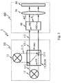
- the embodiment shown in Fig. 5 is mainly based on so-called integrator rods 51 or light pipes 51 as light integrating devices 50 for said light collecting, integrating and redirecting unit 20.
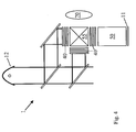
- Fig. 4 demonstrates a hybrid situation for an inventive illumination unit 10 where for two different spectral ranges a high pressure lamp 12 is used as a part of said light source device. Additionally, a solid state light source device 11 is employed in the embodiment of Fig. 4 to supply primary and therefore secondary illumination light L1 and L2, respectively, of a color or spectral range sufficiently contained in the light of the high pressure lamp 12 to improve the color properties of the mixed light being emitted by the light mixing device 55 after the mixing process during which also the uniformization takes place.
- the uniformization may take place before the mixing device and may be done by using either fly-eye lenses or integration rods.
- the embodiment of Fig. 5 is adapted to combine types of first primary illumination light L1 from different light emitting diodes 31 or laser diodes forming an array 33 and the first light source device 11 and having e.g. different spectral or color properties with primary illumination light L12 of a UHP lamp 32 to form combined primary illumination light CL1 as well as secondary illumination light L2.
- second primary illumination light L12 from the UHP lamp 32 forming a second light source device 12 enters the integration rod 51 forming the light integrating device 50 of the light collecting, integrating and redirecting unit 20 directly through the front face of the light entrance section 50I, 51I or the main light entrance area 50I, 51I.
- first primary illumination light L11 from the different light emitting diodes 31 enters the integration rod or integrator rod 51 through its side walls or side faces 50s, 51s.
- said integrator rod 51 comprises within its structure a plurality of the above-mentioned light combining devices 15 in the form of dichroic band-pass filters 15-3. Therefore, said combined primary illumination light CL1 is formed simultaneously with an process of integrating and uniformizing the different kinds of primary illumination light L11 and L12 with the structure of the light collecting, integrating and redirecting unit 20.
Priority Applications (3)
| Application Number | Priority Date | Filing Date | Title |
|---|---|---|---|
| EP03015976A EP1499136A1 (de) | 2003-07-14 | 2003-07-14 | Beleuchtungseinheit, Projektionanzeigeaufbau und Verfahren zur Erzeugung von Beleuchtung |
| US10/889,572 US7035015B2 (en) | 2003-07-14 | 2004-07-12 | Illumination unit, projecting engine and method for generating illumination light |
| JP2004206126A JP2005049851A (ja) | 2003-07-14 | 2004-07-13 | 照明装置、投射エンジン及び照明光の生成方法 |
Applications Claiming Priority (1)
| Application Number | Priority Date | Filing Date | Title |
|---|---|---|---|
| EP03015976A EP1499136A1 (de) | 2003-07-14 | 2003-07-14 | Beleuchtungseinheit, Projektionanzeigeaufbau und Verfahren zur Erzeugung von Beleuchtung |
Publications (1)
| Publication Number | Publication Date |
|---|---|
| EP1499136A1 true EP1499136A1 (de) | 2005-01-19 |
Family
ID=33462111
Family Applications (1)
| Application Number | Title | Priority Date | Filing Date |
|---|---|---|---|
| EP03015976A Withdrawn EP1499136A1 (de) | 2003-07-14 | 2003-07-14 | Beleuchtungseinheit, Projektionanzeigeaufbau und Verfahren zur Erzeugung von Beleuchtung |
Country Status (3)
| Country | Link |
|---|---|
| US (1) | US7035015B2 (de) |
| EP (1) | EP1499136A1 (de) |
| JP (1) | JP2005049851A (de) |
Cited By (6)
| Publication number | Priority date | Publication date | Assignee | Title |
|---|---|---|---|---|
| DE102004011171A1 (de) * | 2004-03-08 | 2005-09-29 | Carl Zeiss Jena Gmbh | Lichtmischstab |
| WO2005120081A1 (en) * | 2004-05-26 | 2005-12-15 | Thomson Licensing | Light engine architecture |
| DE102005013950A1 (de) * | 2005-03-26 | 2006-09-28 | Carl Zeiss Jena Gmbh | Anordnung zur Beleuchtung einer Bildebene |
| WO2006135469A1 (en) * | 2005-06-08 | 2006-12-21 | Tte Technology, Inc. | A system and method for projecting a video image with a temporal led combiner |
| DE102005028671A1 (de) * | 2005-06-17 | 2006-12-28 | Carl Zeiss Jena Gmbh | Verfahren zur Steuerung der Farbanteile einer Beleuchtungsanordnung |
| EP1816512A1 (de) * | 2004-10-29 | 2007-08-08 | Sharp Kabushiki Kaisha | Optischer integrator, illuminator und projektionsbildanzeige |
Families Citing this family (19)
| Publication number | Priority date | Publication date | Assignee | Title |
|---|---|---|---|---|
| US7520624B2 (en) * | 2001-12-21 | 2009-04-21 | Bose Corporation | Light enhancing |
| US7515336B2 (en) | 2001-12-21 | 2009-04-07 | Bose Corporation | Selective reflecting |
| US20050231800A1 (en) * | 2001-12-21 | 2005-10-20 | Barret Lippey | Selective reflecting |
| US6847483B2 (en) * | 2001-12-21 | 2005-01-25 | Bose Corporation | Selective reflecting |
| EP1561349B1 (de) * | 2002-11-07 | 2011-05-04 | Sony Deutschland GmbH | Beleuchtungsanordnung für eine projektionsvorrichtung |
| EP1687931B1 (de) | 2003-10-28 | 2021-12-29 | BlackBerry Limited | Verfahren und vorrichtung zur verifizierbaren erzeugung öffentlicher schlüssel |
| JP4118244B2 (ja) * | 2004-03-29 | 2008-07-16 | 三洋電機株式会社 | 照明装置及び投写型映像表示装置 |
| US7517091B2 (en) * | 2005-05-12 | 2009-04-14 | Bose Corporation | Color gamut improvement in presence of ambient light |
| JP5017817B2 (ja) * | 2005-08-29 | 2012-09-05 | ソニー株式会社 | 虚像光学装置 |
| JP4483763B2 (ja) * | 2005-10-19 | 2010-06-16 | セイコーエプソン株式会社 | 照明装置および画像表示装置 |
| JP4799393B2 (ja) * | 2006-12-20 | 2011-10-26 | 京セラ株式会社 | 照明装置 |
| US8081368B2 (en) * | 2007-03-29 | 2011-12-20 | Bose Corporation | Selective absorbing |
| US7710645B2 (en) * | 2007-06-29 | 2010-05-04 | Bose Corporation | Selective reflecting for laser projector |
| US8132919B2 (en) * | 2009-04-30 | 2012-03-13 | Eastman Kodak Company | Digital projector using arrayed light sources |
| US8066389B2 (en) * | 2009-04-30 | 2011-11-29 | Eastman Kodak Company | Beam alignment chamber providing divergence correction |
| US8033666B2 (en) * | 2009-05-28 | 2011-10-11 | Eastman Kodak Company | Beam alignment system using arrayed light sources |
| US8040078B1 (en) | 2009-06-09 | 2011-10-18 | Koninklijke Philips Electronics N.V. | LED dimming circuit |
| US8545029B2 (en) * | 2011-04-26 | 2013-10-01 | Christie Digital Systems Usa, Inc. | Hybrid high pressure mercury arc lamp-laser light production system |
| CN109143453B (zh) * | 2018-09-28 | 2019-12-24 | 中国科学院长春光学精密机械与物理研究所 | 半导体激光背光模组及液晶显示器 |
Citations (6)
| Publication number | Priority date | Publication date | Assignee | Title |
|---|---|---|---|---|
| JP2001183763A (ja) * | 1999-12-27 | 2001-07-06 | Nikon Corp | 照明光学装置及びこれを具えたた投射型表示装置 |
| US20010048493A1 (en) * | 1994-10-27 | 2001-12-06 | Massachusetts Institute Of Technology | Method of imaging using a liquid crystal display device |
| US20010048560A1 (en) * | 2000-05-31 | 2001-12-06 | Yasuyuki Sugano | Display apparatus |
| US6505939B1 (en) * | 1999-04-23 | 2003-01-14 | Koninklijke Philips Electronics N.V. | Projection system comprising at least two light sources having a unique optical arrangement with respect to at least one spatial light modulator |
| WO2003005733A1 (en) * | 2001-07-06 | 2003-01-16 | Explay Ltd. | An image projecting device and method |
| US20030030913A1 (en) * | 2001-08-10 | 2003-02-13 | Tae Soo Park | Optical device with a function of homogenizing and color separation, and optical illumination system for a projector using the same |
Family Cites Families (3)
| Publication number | Priority date | Publication date | Assignee | Title |
|---|---|---|---|---|
| JPH08160374A (ja) * | 1994-12-01 | 1996-06-21 | Mitsubishi Electric Corp | プロジェクタ装置 |
| US6390626B2 (en) * | 1996-10-17 | 2002-05-21 | Duke University | Image projection system engine assembly |
| US6871982B2 (en) * | 2003-01-24 | 2005-03-29 | Digital Optics International Corporation | High-density illumination system |
-
2003
- 2003-07-14 EP EP03015976A patent/EP1499136A1/de not_active Withdrawn
-
2004
- 2004-07-12 US US10/889,572 patent/US7035015B2/en not_active Expired - Fee Related
- 2004-07-13 JP JP2004206126A patent/JP2005049851A/ja not_active Withdrawn
Patent Citations (6)
| Publication number | Priority date | Publication date | Assignee | Title |
|---|---|---|---|---|
| US20010048493A1 (en) * | 1994-10-27 | 2001-12-06 | Massachusetts Institute Of Technology | Method of imaging using a liquid crystal display device |
| US6505939B1 (en) * | 1999-04-23 | 2003-01-14 | Koninklijke Philips Electronics N.V. | Projection system comprising at least two light sources having a unique optical arrangement with respect to at least one spatial light modulator |
| JP2001183763A (ja) * | 1999-12-27 | 2001-07-06 | Nikon Corp | 照明光学装置及びこれを具えたた投射型表示装置 |
| US20010048560A1 (en) * | 2000-05-31 | 2001-12-06 | Yasuyuki Sugano | Display apparatus |
| WO2003005733A1 (en) * | 2001-07-06 | 2003-01-16 | Explay Ltd. | An image projecting device and method |
| US20030030913A1 (en) * | 2001-08-10 | 2003-02-13 | Tae Soo Park | Optical device with a function of homogenizing and color separation, and optical illumination system for a projector using the same |
Cited By (10)
| Publication number | Priority date | Publication date | Assignee | Title |
|---|---|---|---|---|
| DE102004011171A1 (de) * | 2004-03-08 | 2005-09-29 | Carl Zeiss Jena Gmbh | Lichtmischstab |
| DE102004011171B4 (de) * | 2004-03-08 | 2016-02-04 | Carl Zeiss Ag | Lichtmischstab |
| WO2005120081A1 (en) * | 2004-05-26 | 2005-12-15 | Thomson Licensing | Light engine architecture |
| EP1816512A1 (de) * | 2004-10-29 | 2007-08-08 | Sharp Kabushiki Kaisha | Optischer integrator, illuminator und projektionsbildanzeige |
| EP1816512A4 (de) * | 2004-10-29 | 2010-08-11 | Sharp Kk | Optischer integrator, illuminator und projektionsbildanzeige |
| DE102005013950A1 (de) * | 2005-03-26 | 2006-09-28 | Carl Zeiss Jena Gmbh | Anordnung zur Beleuchtung einer Bildebene |
| WO2006135469A1 (en) * | 2005-06-08 | 2006-12-21 | Tte Technology, Inc. | A system and method for projecting a video image with a temporal led combiner |
| US7281806B2 (en) | 2005-06-08 | 2007-10-16 | Tte Technology, Inc. | System and method for projecting a video image with a temporal LED combiner |
| DE102005028671A1 (de) * | 2005-06-17 | 2006-12-28 | Carl Zeiss Jena Gmbh | Verfahren zur Steuerung der Farbanteile einer Beleuchtungsanordnung |
| DE102005028671B4 (de) * | 2005-06-17 | 2007-11-29 | Carl Zeiss Jena Gmbh | Verfahren zur Einstellung der Farbanteile einer Beleuchtungsanordnung |
Also Published As
| Publication number | Publication date |
|---|---|
| US20050099698A1 (en) | 2005-05-12 |
| US7035015B2 (en) | 2006-04-25 |
| JP2005049851A (ja) | 2005-02-24 |
Similar Documents
| Publication | Publication Date | Title |
|---|---|---|
| US7035015B2 (en) | Illumination unit, projecting engine and method for generating illumination light | |
| US7090357B2 (en) | Combined light source for projection display | |
| JP6084666B2 (ja) | 投影装置 | |
| CN107430319B (zh) | 投影仪和图像光投射方法 | |
| US9201295B2 (en) | High efficiency LED optical engine for a digital light processing (DLP) projector and method of forming same | |
| US10831087B2 (en) | Illumination system and projection apparatus | |
| US9146452B2 (en) | Multi-color illumination apparatus | |
| EP1816512A1 (de) | Optischer integrator, illuminator und projektionsbildanzeige | |
| JPH11149061A (ja) | 光源装置および照明装置 | |
| JP2006337609A (ja) | 照明装置、投写型映像表示装置 | |
| US10185214B2 (en) | Projector and image display method including a light separation optical system | |
| US20190253676A1 (en) | Illumination system and projection apparatus | |
| TWI656361B (zh) | 照明系統與投影裝置 | |
| US20150286127A1 (en) | Projector | |
| JP2005116266A (ja) | 照明装置、表示装置及びプロジェクタ | |
| JP4143533B2 (ja) | 光源装置、画像表示装置 | |
| JP2004070017A (ja) | 投写装置の照明光学系構造及び投写装置 | |
| TW201316112A (zh) | 照明系統與投影裝置 | |
| KR100606775B1 (ko) | Led 조명장치 및 이를 이용한 광학계 | |
| JPH1164792A (ja) | 照明装置および画像投影装置 | |
| CN112346290A (zh) | 照明系统以及投影装置 | |
| JP2004286964A (ja) | 色分離方法、色合成方法、及び表示装置 | |
| MXPA06007142A (es) | Fuente luminosa combinada para pantalla de proyeccion | |
| KR20080041035A (ko) | 광 합성 유닛 및 이를 갖는 디스플레이장치 |
Legal Events
| Date | Code | Title | Description |
|---|---|---|---|
| PUAI | Public reference made under article 153(3) epc to a published international application that has entered the european phase |
Free format text: ORIGINAL CODE: 0009012 |
|
| AK | Designated contracting states |
Kind code of ref document: A1 Designated state(s): AT BE BG CH CY CZ DE DK EE ES FI FR GB GR HU IE IT LI LU MC NL PT RO SE SI SK TR |
|
| AX | Request for extension of the european patent |
Extension state: AL LT LV MK |
|
| RIN1 | Information on inventor provided before grant (corrected) |
Inventor name: TEIJIDO, JUAN MANUEL,C/O STUTTGART TECHN. CENTER |
|
| 17P | Request for examination filed |
Effective date: 20050309 |
|
| RAP1 | Party data changed (applicant data changed or rights of an application transferred) |
Owner name: SONY DEUTSCHLAND GMBH |
|
| AKX | Designation fees paid |
Designated state(s): DE FR GB |
|
| RAP1 | Party data changed (applicant data changed or rights of an application transferred) |
Owner name: SONY DEUTSCHLAND GMBH |
|
| 17Q | First examination report despatched |
Effective date: 20080521 |
|
| STAA | Information on the status of an ep patent application or granted ep patent |
Free format text: STATUS: THE APPLICATION IS DEEMED TO BE WITHDRAWN |
|
| 18D | Application deemed to be withdrawn |
Effective date: 20081001 |