EP1499009A1 - Steuer- und Schutzgerät für ein doppelgespeistes Induktionsgeneratorsystem - Google Patents
Steuer- und Schutzgerät für ein doppelgespeistes Induktionsgeneratorsystem Download PDFInfo
- Publication number
- EP1499009A1 EP1499009A1 EP20030380174 EP03380174A EP1499009A1 EP 1499009 A1 EP1499009 A1 EP 1499009A1 EP 20030380174 EP20030380174 EP 20030380174 EP 03380174 A EP03380174 A EP 03380174A EP 1499009 A1 EP1499009 A1 EP 1499009A1
- Authority
- EP
- European Patent Office
- Prior art keywords
- rotor
- windings
- operating state
- clamping unit
- grid
- Prior art date
- Legal status (The legal status is an assumption and is not a legal conclusion. Google has not performed a legal analysis and makes no representation as to the accuracy of the status listed.)
- Granted
Links
- 230000006698 induction Effects 0.000 title claims abstract description 15
- 238000004804 winding Methods 0.000 claims abstract description 83
- 230000001960 triggered effect Effects 0.000 claims abstract description 25
- 230000001419 dependent effect Effects 0.000 claims abstract description 18
- 238000000034 method Methods 0.000 claims abstract description 9
- 238000010248 power generation Methods 0.000 claims abstract description 9
- 230000001629 suppression Effects 0.000 claims description 4
- 238000001514 detection method Methods 0.000 claims description 2
- 239000004568 cement Substances 0.000 claims 1
- 230000007423 decrease Effects 0.000 description 6
- 238000007599 discharging Methods 0.000 description 2
- 239000000654 additive Substances 0.000 description 1
- 230000033228 biological regulation Effects 0.000 description 1
- 238000012886 linear function Methods 0.000 description 1
- 230000001360 synchronised effect Effects 0.000 description 1
- 230000001131 transforming effect Effects 0.000 description 1
- 230000001052 transient effect Effects 0.000 description 1
Images


Classifications
-
- H—ELECTRICITY
- H02—GENERATION; CONVERSION OR DISTRIBUTION OF ELECTRIC POWER
- H02P—CONTROL OR REGULATION OF ELECTRIC MOTORS, ELECTRIC GENERATORS OR DYNAMO-ELECTRIC CONVERTERS; CONTROLLING TRANSFORMERS, REACTORS OR CHOKE COILS
- H02P9/00—Arrangements for controlling electric generators for the purpose of obtaining a desired output
- H02P9/10—Control effected upon generator excitation circuit to reduce harmful effects of overloads or transients, e.g. sudden application of load, sudden removal of load, sudden change of load
- H02P9/102—Control effected upon generator excitation circuit to reduce harmful effects of overloads or transients, e.g. sudden application of load, sudden removal of load, sudden change of load for limiting effects of transients
-
- F—MECHANICAL ENGINEERING; LIGHTING; HEATING; WEAPONS; BLASTING
- F03—MACHINES OR ENGINES FOR LIQUIDS; WIND, SPRING, OR WEIGHT MOTORS; PRODUCING MECHANICAL POWER OR A REACTIVE PROPULSIVE THRUST, NOT OTHERWISE PROVIDED FOR
- F03D—WIND MOTORS
- F03D9/00—Adaptations of wind motors for special use; Combinations of wind motors with apparatus driven thereby; Wind motors specially adapted for installation in particular locations
- F03D9/20—Wind motors characterised by the driven apparatus
- F03D9/25—Wind motors characterised by the driven apparatus the apparatus being an electrical generator
- F03D9/255—Wind motors characterised by the driven apparatus the apparatus being an electrical generator connected to electrical distribution networks; Arrangements therefor
-
- H—ELECTRICITY
- H02—GENERATION; CONVERSION OR DISTRIBUTION OF ELECTRIC POWER
- H02P—CONTROL OR REGULATION OF ELECTRIC MOTORS, ELECTRIC GENERATORS OR DYNAMO-ELECTRIC CONVERTERS; CONTROLLING TRANSFORMERS, REACTORS OR CHOKE COILS
- H02P6/00—Arrangements for controlling synchronous motors or other dynamo-electric motors using electronic commutation dependent on the rotor position; Electronic commutators therefor
- H02P6/005—Arrangements for controlling doubly fed motors
-
- H—ELECTRICITY
- H02—GENERATION; CONVERSION OR DISTRIBUTION OF ELECTRIC POWER
- H02P—CONTROL OR REGULATION OF ELECTRIC MOTORS, ELECTRIC GENERATORS OR DYNAMO-ELECTRIC CONVERTERS; CONTROLLING TRANSFORMERS, REACTORS OR CHOKE COILS
- H02P9/00—Arrangements for controlling electric generators for the purpose of obtaining a desired output
- H02P9/007—Control circuits for doubly fed generators
-
- H—ELECTRICITY
- H02—GENERATION; CONVERSION OR DISTRIBUTION OF ELECTRIC POWER
- H02P—CONTROL OR REGULATION OF ELECTRIC MOTORS, ELECTRIC GENERATORS OR DYNAMO-ELECTRIC CONVERTERS; CONTROLLING TRANSFORMERS, REACTORS OR CHOKE COILS
- H02P2101/00—Special adaptation of control arrangements for generators
- H02P2101/15—Special adaptation of control arrangements for generators for wind-driven turbines
-
- Y—GENERAL TAGGING OF NEW TECHNOLOGICAL DEVELOPMENTS; GENERAL TAGGING OF CROSS-SECTIONAL TECHNOLOGIES SPANNING OVER SEVERAL SECTIONS OF THE IPC; TECHNICAL SUBJECTS COVERED BY FORMER USPC CROSS-REFERENCE ART COLLECTIONS [XRACs] AND DIGESTS
- Y02—TECHNOLOGIES OR APPLICATIONS FOR MITIGATION OR ADAPTATION AGAINST CLIMATE CHANGE
- Y02E—REDUCTION OF GREENHOUSE GAS [GHG] EMISSIONS, RELATED TO ENERGY GENERATION, TRANSMISSION OR DISTRIBUTION
- Y02E10/00—Energy generation through renewable energy sources
- Y02E10/70—Wind energy
- Y02E10/72—Wind turbines with rotation axis in wind direction
Definitions
- the invention relates to the control of a Double-fed Induction Generator ("DFIG), especially for use in wind-power generation.
- DFIG Double-fed Induction Generator
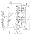
- a conventional DFIG system is shown in Figure 1 .
- a rotor 1 of a generator comprising an electric multiphase (in this case, 3-phase) asynchronous machine is connected, through a gear-box 4, to a shaft 5 driven by the blades 3 of a wind-turbine.
- the windings of the stator 2 of the generator are connected, through a switch 6, to output lines 100 connected to a transformer 101 by means of which the output lines are connected to the electric power distribution network or grid 102, normally a medium voltage (10 kV - 40 kV) grid.
- the voltage on the output lines from the stator is normally in the order of 690 V (considered to be the normal operation voltage level of the stator).
- the system further includes a converter 7 having a rotor-side inverter or rotor-inverter (71, 72, 73) connected to the windings of the rotor through control lines 8, each control line including an inductor 9.
- the converter 7 further comprises a grid-side inverter or grid-inverter (74, 75, 76) connected to the above-mentioned output lines 100 (and, thus, to the grid) through grid-inverter connection lines 103, coupled to a transformer 104 (typically, for transforming from a level of 480 V on the converter side to 690 V on the output line side).
- the transformer is connected to the output lines 100 through a switch arrangement comprising two switches arranged in parallel: a main switch 105 arranged directly between the output lines 100 and the transformer 104, and a charge switch 106 connected in series with a charge resistor 107. That is, the grid-inverter is connected to the grid and to the stator windings, through the transformer 104.
- each one of said rotor-inverter and grid-inverter comprises three half-bridges (71, 72, 73; 74, 75, 76) connected in parallel, one half-bridge for each phase of the generator and grid, respectively.
- the rotor-inverter (71, 72, 73) is fed by a DC-link 77.
- the grid-inverter (74, 75, 76) controls the voltage over the DC-link 77.
- Each half-bridge (71, 72, 73; 74, 75, 76) is made up of two identical units connected in series, each unit comprising an IGBT (Insulated Gate Bipolar Transistor) 78 connected in parallel with a free-wheel diode 79.
- IGBT Insulated Gate Bipolar Transistor
- the half-bridge is connected to:
- control module 80 arranged to receive a plurality of input signals corresponding to the values of several parameters of the system, including:
- control module 80 can control the PWM (Pulse Width Modulation) of the two inverters.
- the control module 80 receives a power reference signal (PRS) coming from the main wind-turbine controller (not shown in figure 1 ), which is arranged to receive information such as the actual power supplied by the generator, the positions of the blades, wind-speed, etc.
- PRS power reference signal
- the main wind-turbine controller is responsible for the total operation of the wind-turbine and controls a plurality of sub-controllers, including the converter 7.
- the power reference signal is compared with the measured power (based on the measured values of I G and U G ) and the output of a power regulation loop of the control module 80 controls the PWM of the rotor-inverter.
- the DC-link is controlled by the grid-inverter.
- the DC-link voltage is constant when the converter operates under normal conditions. In the circuit of the present example ( figure 1 ), the DC-link voltage can, under normal conditions, be around 800 V DC .
- the converter 7 operates as follows:
- the charge switch 106 is closed. Then the DC-link 77 will be charged over the charge resistor 107 and the free-wheel diodes 79 of the grid-inverter. The voltage over the DC-link is measured by the control module 80. When the voltage over the DC-link reaches a pre-determined level, the main switch 105 is closed and the charge switch 106 is opened.
- the grid-inverter After the main switch 105 is closed, the grid-inverter is started and the DC-link voltage will be controlled by the grid inverter, so as to keep the voltage over the DC-link at a rated value (in this example, around 800 V DC ).
- the grid-inverter can supply the grid with power (like a generator) or it can take power from the grid (like a motor).
- the grid-inverter operates in accordance with the voltage over the DC-link: if this voltage tends to increase (due to input from the rotor-inverter), the grid-inverter supplies power to the grid; if the voltage over the DC-link tends to decrease, the grid-inverter takes power from the grid.
- the rotor-inverter is started; that means that the control module 80 starts to operate the PWM of the rotor-inverter, triggering and not triggering, respectively, each IGBT 78 of the halfbridges (71-73) of the rotor-inverter. With the resulting rotor-current/rotor-voltage, the control module 80 controls the stator-side (as the generator acts as a transformer).
- the control module 80 measures an AC voltage (U S in the drawings, sometimes also known as U SYNC ) and controls the rotor-inverter (adjusting the PWM) until this stator voltage U S is identical with the grid-voltage U G . Once both voltages are identical, the switch 6 is closed, thus connecting the stator windings to the grid. With the PWM of the rotor-inverter it is now possible to control the active and reactive -power of the total power supplied to the grid.
- the power-electronic components of the converter 7 need to be protected against high currents (over-currents) and over-voltages that can appear in the control lines 8 connecting the rotor windings with the rotor-inverter.
- high currents over-currents
- over-voltages that can appear in the control lines 8 connecting the rotor windings with the rotor-inverter.
- the generator 2 feed high stator-currents (I s ) into the short-circuit and the rotor-currents increase very rapidly.
- the switch 6 connecting the generator to the grid is then opened, but there is a substantial delay (typically around 50 ms) before disconnection actually takes place, and during this time, the high rotor-currents can harm the converter.
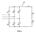
- the converter 7 In order to protect the converter, it is known to provide the converter 7 with a so-called “crowbar" 90, arranged so as to short-circuit the rotor windings, when necessary, so as to absorb the rotor-currents and prevent them from entering the rotor-inverter and harming components thereof.
- a typical example of the basic layout of a known crowbar is shown in figure 2 .
- the crowbar comprises three branches arranged in parallel, each branch comprising two diodes (91, 92; 93, 94; 95, 96) connected in series. Between the two diodes in each branch, there is a point of connection of the crowbar to the respective rotor winding. In series with the three branches comprising the diodes, there is a further branch comprising a power thyristor 98 and, optionally, a resistor 97.
- the crowbar is operated in the following manner:
- control module 80 fires the power thyristor 98 of the crowbar, permitting the currents to flow through said thyristor. Then, the high rotor-currents will start to flow through the diodes of the crowbar instead of through the rotor-inverter. The rotor-voltage will be nearly zero, as the crowbar acts as a shortcircuit.
- the switch 6 is opened, thus disconnecting the stator 2 from the grid; the generator will then be demagnetised over said switch 6 and the crowbar 90. After this, the generator can be connected to the grid again, once the grid-voltage has returned to the rated value.
- Figures 3A-3G show, using the same time axis, the development of some of the parameters of a system according to figure 1 with a prior art crowbar as per figure 2, when a short-circuit is produced in the grid.
- the following points of time are referred to:
- Figure 3A shows the drop of U G by the time t1 (time for short circuit in the grid).
- FIG. 3B shows the stator-current I s .
- the stator-current starts to increase rapidly and it remains on a high level until the time t3, when the switch 6 is opened, thus disconnecting the stator from the grid (then, the stator-current is interrupted). Later, once the voltage on the grid has returned to its rated value, the generator is reconnected to the grid (at t4) and the stator-currents start to flow again.
- Figure 3C shows how the rotor-current I R changes almost in the same way as the stator-current (due to the fact that the rotor and stator act as the primary and secondary sides of a transformer). The only difference is due to the fact that the magnetising current for the generator is coming from the rotor-side. Thus, in figure 3C , shortly before t4, a small magnetising current can be observed.
- Figure 3D shows the current from the rotor to the rotor-inverter (I L ).
- this rotor-inverter current increases rapidly (following the increase in the rotor-currents, which are all fed to the rotor-inverter).
- the rotor-inverter is stopped by the control module 80 and the current then flows through the free-wheel diodes 79, into the DC-link.
- the voltage over the DC-link (U DC ) (cf. figure 3E ) increases very fast, until it reaches a certain level. Then, by the time t2, the crowbar is triggered by the control module (which has been reading the voltage over the DC-link).
- the rotor-current is then commutated into the crowbar (and I L almost immediately sinks to zero, that is, no current is fed from the rotor into the converter 7).
- the rotor-inverter starts to supply the magnetising current to the rotor of the generator, and synchronises with the grid.
- the rotor-current increases again to the rated value (cf. figure 3C ) (if there is enough energy in the wind).
- FIG 3E it is shown how, at t1, the DC-link is charged rapidly (the voltage U DC over the DC-link thus increases). At t2, the crowbar is triggered and the charging is stopped. The discharging of the DC-link is done by the grid-inverter. The grid-inverter discharges the DC-link down to the rated value (800 V DC ).
- Figure 3F shows the current through the crowbar I CR .
- the crowbar overtakes the total rotor-current.
- figure 3G shows the rotor-voltage U R .
- the rotor-voltage is at its normal operation level.
- the rotor-inverter is stopped and rectified rotor-voltage jumps to the level of the DC-link.
- the rotor-voltage increases with the voltage over the DC-link, until t2, when the crowbar is triggered; then, the rotor is shortcircuited and the rotor-voltage sinks to zero.
- the switch 6 is opened and the generator is disconnected from the grid, the crowbar is opened again.
- the rotor-inverter is synchronised and the rotor-voltage is back at its normal operation level again.
- the disconnection of the generator from the grid has traditionally been used so as to protect the generator and converter when problems occur on the grid (such as short-circuits giving rise to rotor-current surges), and also for reasons related with the network management.
- the disconnection has not been considered to imply any substantial problems in what regards the over-all supply of power to the grid, as the wind-power generators have represented a very small part of the total power supplied to the grid (typically, below 5 % of the total power supply).
- wind-power generation is representing a rapidly increasing portion of the electric power generation
- the wind-power generation represents such an important part of the total power generation that sudden disconnection of the wind-power generators can cause severe problems to the over-all electric power distribution over the grid.
- this solution requires that the free-wheel diodes of the rotor-inverter are chosen so as to support high currents (as the rotor currents will continue to flow through the free-wheel diodes of the rotor-inverter). Further, the chopper needs a switch that can be switched off, like a GTO or IGBT, that is, an active switch. Further, for protection reasons, there must be a crowbar arranged in parallel with the rotor-inverter.
- the arrangement should not require any crowbar.
- a first aspect of the invention relates to a control system for a double-fed induction generator (DFIG) comprising a rotor having rotor windings and a stator having stator windings connectable to a grid for electric power distribution, said control system comprising a converter, said converter comprising the following components:
- the converter further comprises a clamping unit for protecting the converter from damage due to over-currents in the rotor windings, said clamping unit being connectable over the rotor windings and arranged to be triggered from a non-operating state to an operating state following detection of an over-current in the rotor-windings, said clamping unit comprising a clamping element arranged so that when the clamping unit is in its non-operating state, currents in the rotor windings cannot pass through said clamping element, and when the clamping unit is in its operating state, currents in the rotor windings can pass through said clamping element.
- the clamping element comprises at least one passive voltage-dependent resistor element for providing a clamping voltage over the rotor windings.
- the voltage-dependent resistor element can be chosen so that, for any expected value of the rotor-currents occurring during short-circuit in the grid, an appropriate clamping voltage will be obtained over the clamping element and, thus, over the rotor windings. It is important that said clamping voltage be within a predetermined range. Especially, it should not be allowed to be too low, as a too low clamping voltage would imply that the currents in the rotor windings would decrease very slowly (as long as the stator remains connected to the grid). Actually, if the clamping voltage is below the level of the rotor voltage during normal operation, the rotor currents will never go down to zero.
- the rotor-currents decrease as rapidly as possible, so as to allow the converter to start to operate again, by means of bringing the clamping unit back to its non-operating state (whereby the rotor-currents are commutated to the rotor-inverter again), so that the converter can take over the control of the generator again. It is considered to be important that the converter will be able to take over the control of the rotor currents as soon as possible, so as to be able to control the power output to the grid also during the duration of the short-circuit on the grid (this is normally required by the operator of the grid).
- the clamping element be a voltage-dependent resistor element, so that the voltage will not be a purely linear function of the rotor currents: the use of a normal resistor would imply that the clamping voltage would be (substantially) directly proportional to the rotor currents at each moment. Were a resistor chosen, care would have to be taken so as to choose a resistance value low enough to make sure that the clamping voltage would never exceed a maximum level allowed for the rotor-voltage, not even if the current flowing through the resistor would reach the highest level of rotor-current that could be expected.
- a passive voltage-dependent resistor element is especially advantageous, as it provides for a rather well-defined clamping voltage without requiring any complex control of the clamping unit. Basically, it is enough to trigger the clamping unit so as to allow the rotor-currents to pass through the clamping unit instead of through the rotor-inverter.
- a simple trigger element such as a power thyristor can be used, which can be arranged in series with the clamping element(s) and the respective rotor winding and be triggered from the control module using a very low current (for example, below 1A, applied through a simple pulse-transformer).
- the clamping of the voltage over the rotor-windings is achieved by the voltage-dependent resistor element itself, and no further control is needed. That is, no “active" control of this clamping voltage is needed; once the stator-current is below its rated value, the control module can simply stop the triggering of the thyristors and, thus, stop the rotor-currents from flowing through the clamping unit after the next zero-crossing of the current through the thyristor.
- the clamping element can comprise a plurality of passive voltage-dependent resistor elements, arranged in parallel, thereby allowing very high rotor-currents to flow through the clamping element without harming the individual passive voltage-dependent resistor elements.
- the passive voltage-dependent resistor element(s) can (each) comprise:
- Suitable passive voltage-dependent resistor elements are the following ones:
- the clamping unit can comprise, for each phase of the rotor, a connector for connection to the respective rotor phase, each connector being connected to a trigger branch comprising, in series: a point of connection of the clamping unit to the connector for connection to the respective rotor phase; a thyristor for triggering the clamping unit; the clamping element; a diode; and the point of connection to the connector for connection to the respective rotor phase.
- the clamping unit can further comprise a resistor coupled in parallel with the clamping element.
- the clamping unit can be arranged to be triggered from a non-operating state to an operating state:
- a second aspect of the invention relates to a double-fed induction generator (DFIG) system comprising a rotor having rotor windings and a stator having stator windings connectable to a grid for electric power distribution, said double-fed induction generator system further comprising a control system as described above, the rotor inverter being connected to the rotor windings of the generator, the grid inverter being connected to the grid, and the clamping unit being connected over the rotor windings.
- DFIG double-fed induction generator
- a third aspect of the invention relates to a method for protecting the converter in a power generation system comprising a double-fed induction generator (DFIG) comprising a rotor having rotor windings, a stator having stator windings connected to a grid for electric power distribution and a control system comprising a converter, said converter comprising a rotor-inverter connected to the rotor windings of the generator, a grid-inverter connected to the grid and/or to the stator windings, and a DC-link for feeding the rotor-inverter.
- the method comprises the steps of:
- the clamping unit can be triggered from a non-operating state to an operating state, for example,
- FIGS 5 and 6 illustrate two preferred embodiments of the invention. Most of the illustrated components correspond exactly to those of the prior art system described referring to figure 1 ; these components bear the same reference numerals and need no further description. However, instead of the converter 7 of figure 2, figures 5 and 6 illustrate converters comprising the same basic elements but:
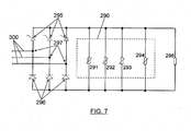
- Figure 7 illustrates a preferred embodiment of the clamping unit clamping unit comprising, for each phase of the rotor, a connector (300) for connection to the respective rotor phase.
- Each connector is connected to a trigger branch comprising, in series: a point of connection (297) of the clamping unit to the connector (300) for connection to the respective rotor phase; a thyristor (295) for triggering the clamping unit; the clamping element (290); a diode (296); and the point of connection (297) to the connector (300) for connection to the respective rotor phase.
- the thyristor 295 and the diode 296 can be integrated in one single component, such as SKKH210/12E from Semikron.
- the clamping element 290 can be a varistor such as B80K320 from EPCOS.
- a thyristor could be used, with the advantage that the delay between the stopping of the triggering of the clamping unit and the actual stopping of the current flowing through the clamping unit is reduced by up to 50%, compared to when a diode is used).
- FIG. 4A shows the grid-voltage, with a short-circuit appearing by t11. Then, the stator-current I s ( Figure 4B) increases rapidly. However, in this case, the generator is not disconnected and will be demagnetized over the stator- and rotor-currents and the stator- and rotor-currents will then decrease. Once the stator-currents are below the rated level (approximately by t13) the clamping unit 190 will be opened by the control module (180, 181) and the rotor-currents will flow into the rotor-inverter again. The converter measures the rotor-currents (by measuring the currents I L in the control lines) and synchronises the PWM with those currents.
- the rotor-inverter controls the rotor-currents and provides for a constant rotor- and stator-current all through the remaining duration of the short-circuit (from t14 to t15 in figures 4B and 4C). Later, when the grid-voltage returns to its rated value, the generator is not magnetised enough and from the grid a high current flows to the stator and produces an over-current (in the interval between t15 and t17 in figure 4C). The rotor-inverter is then stopped again, and the generator will be magnetised from the grid. After this, the stator-current decreases and, once it is under the rated value (t17), the clamping unit 190 is opened and the rotor-inverter overtakes the control of the rotor-current again.
- the rotor-current (I R ) (figure 4C) is nearly the same as the stator-current.
- Figure 4D shows the current I L to the rotor-inverter (that is, the current from the rotor to the converter).
- the clamping unit 190 is triggered (just as the crowbar was triggered in the prior art system described above).
- the rotor-current is commutated into the clamping unit 190 and I L sinks to zero.
- the clamping unit is opened by the control module (180, 181) and the rotor-current is commutated into the rotor-inverter.
- the rotor-inverter synchronises with the rotor-current and controls the current during the remaining part of the duration of the short-circuit (t14-t15).
- the grid operator requires that the wind-turbine actively supplies a current in the short circuit outside the wind-turbine, in order to provoke a more rapid disconnection of the short-circuit by opening a high voltage circuit breaker in the grid.
- the generator should be controlled during most of the duration of the short-circuit.
- the invention allows the rotor-inverter to be stopped only in the transient times corresponding to the presence of the dynamic over-currents caused by fast voltage changes on the grid).
- the clamping unit 190 When the grid-voltage returns to its rated value (t15), the rotor-current increases rapidly and the rotor-inverter is stopped again (as an over-current is measured by the control module), the clamping unit 190 is triggered and overtakes the rotor-current. When the stator-current sinks below the rated level (t17), the clamping unit is opened and the rotor-current is commutated into the rotor-inverter again. The rotor-inverter synchronises with the actual rotor-current and starts to operate again, controlling the rotor-current.
- Figure 4E shows the voltage over the DC-link.
- t11 there is a first spike, which triggers the clamping unit 190 (at t12).
- the clamping unit is opened and the rotor-current is commutated into the rotor-inverter again, starting to charge the DC-link again (t13), until the rotor-inverter overtakes the control of the rotor-current (this is by the control module -180, 181-, so as to overtake the control of the generator again).
- This happens two times in figure 4E first due to the voltage drop on the grid and the second time when the grid-voltage rises again.
- Figure 4F shows the clamping current (current through the clamping unit) I CL .
- the clamping unit overtakes the full rotor-current two times, as outlined above.
- Figure 4G shows the rotor-voltage U R .
- the rotor-voltage is at its normal operation level.
- the rotor-current increases and the rotor-inverter is stopped.
- the rotor-current is like a current source and flows over the free-wheel diodes 79, into the DC-link 77.
- the rotor-voltage will be at the same level as the voltage over the DC-link.
- the rotor-voltage increases with the increasing DC-link voltage and by t12, the clamping unit is triggered and the rotor-voltage is clamped to a level in accordance with the chosen characteristics of the clamping element 290.
- the clamping unit is opened and the rotor-current flows into the rotor-inverter and the rotor-voltage jumps to the level of the DC-link voltage.
- the rotor-inverter starts to work (t14) and the level of the rotor-voltage is returning to the level corresponding to normal operation. While the short-circuit condition remains on the grid (t14-15), the "normal" rotor-voltage is lower then before t11, because of the drop of the stator-voltage.
- Figure 4H shows the clamping voltage U CL .
- the clamping voltage will change between two well-defined levels, namely, between zero and a clamping level.
Landscapes
- Engineering & Computer Science (AREA)
- Power Engineering (AREA)
- Life Sciences & Earth Sciences (AREA)
- Sustainable Development (AREA)
- Sustainable Energy (AREA)
- Chemical & Material Sciences (AREA)
- Combustion & Propulsion (AREA)
- Mechanical Engineering (AREA)
- General Engineering & Computer Science (AREA)
- Control Of Eletrric Generators (AREA)
Priority Applications (8)
| Application Number | Priority Date | Filing Date | Title |
|---|---|---|---|
| PT03380174T PT1499009E (pt) | 2003-07-15 | 2003-07-15 | Controlo e protecção de um sistema gerador de indução de dupla alimentação |
| DE2003617183 DE60317183T2 (de) | 2003-07-15 | 2003-07-15 | Steuer- und Schutzgerät für ein doppelgespeistes Induktionsgeneratorsystem |
| EP20030380174 EP1499009B1 (de) | 2003-07-15 | 2003-07-15 | Steuer- und Schutzgerät für ein doppelgespeistes Induktionsgeneratorsystem |
| AT03380174T ATE377286T1 (de) | 2003-07-15 | 2003-07-15 | Steuer- und schutzgerät für ein doppelgespeistes induktionsgeneratorsystem |
| US10/563,043 US7518256B2 (en) | 2003-07-15 | 2004-07-01 | Control and protection of a doubly-fed induction generator system |
| KR20067000937A KR100832769B1 (ko) | 2003-07-15 | 2004-07-01 | 이중 권선형 유도 발전기 시스템의 제어 및 보호 |
| CNB2004800198515A CN100424988C (zh) | 2003-07-15 | 2004-07-01 | 双馈感应发电机系统的控制和保护 |
| PCT/EP2004/007208 WO2005015730A1 (en) | 2003-07-15 | 2004-07-01 | Control and protection of a doubly-fed induction generator system |
Applications Claiming Priority (1)
| Application Number | Priority Date | Filing Date | Title |
|---|---|---|---|
| EP20030380174 EP1499009B1 (de) | 2003-07-15 | 2003-07-15 | Steuer- und Schutzgerät für ein doppelgespeistes Induktionsgeneratorsystem |
Publications (2)
| Publication Number | Publication Date |
|---|---|
| EP1499009A1 true EP1499009A1 (de) | 2005-01-19 |
| EP1499009B1 EP1499009B1 (de) | 2007-10-31 |
Family
ID=33462270
Family Applications (1)
| Application Number | Title | Priority Date | Filing Date |
|---|---|---|---|
| EP20030380174 Expired - Lifetime EP1499009B1 (de) | 2003-07-15 | 2003-07-15 | Steuer- und Schutzgerät für ein doppelgespeistes Induktionsgeneratorsystem |
Country Status (8)
| Country | Link |
|---|---|
| US (1) | US7518256B2 (de) |
| EP (1) | EP1499009B1 (de) |
| KR (1) | KR100832769B1 (de) |
| CN (1) | CN100424988C (de) |
| AT (1) | ATE377286T1 (de) |
| DE (1) | DE60317183T2 (de) |
| PT (1) | PT1499009E (de) |
| WO (1) | WO2005015730A1 (de) |
Cited By (23)
| Publication number | Priority date | Publication date | Assignee | Title |
|---|---|---|---|---|
| GB2420456A (en) * | 2004-11-23 | 2006-05-24 | Areva T & D Uk Ltd | Generator control having grid imbalance detector |
| US7215035B2 (en) * | 2005-02-22 | 2007-05-08 | Xantrex Technology, Inc. | Method and apparatus for converting wind generated electricity to constant frequency electricity for a utility grid |
| DE102005051753A1 (de) * | 2005-10-27 | 2007-05-24 | Suzlon Energy Gmbh | Schaltungsanordnung zum Ausschalten einer Crowbar |
| WO2007057480A1 (es) * | 2005-11-21 | 2007-05-24 | Ingeteam Technology, S.A. | Un sistema de control y protección ante faltas simétricas y asimétricas, para generadores de tipo asíncrono |
| WO2007077002A2 (en) * | 2005-12-30 | 2007-07-12 | Universidad Publica De Navarra | Method and system for the protection of an electricity generation facility connected to an electricity network in the presence of voltage sags in said network |
| US7253537B2 (en) | 2005-12-08 | 2007-08-07 | General Electric Company | System and method of operating double fed induction generators |
| DE102006018160A1 (de) * | 2006-04-19 | 2007-10-25 | Siemens Ag | Stromrichterkaskaden-Anordnung |
| WO2009043943A1 (es) * | 2007-10-01 | 2009-04-09 | Ingeteam Energy, S.A. | Método de acoplamiento y regulación de potencia reactiva por estátor para generadores eólicos doblemente alimentados en cualquier condición de viento |
| EP2161821A1 (de) * | 2008-09-03 | 2010-03-10 | General Electric Company | Magnetisch angetriebener Generator |
| CN101917130A (zh) * | 2010-08-05 | 2010-12-15 | 国电南京自动化股份有限公司 | Dfig低压穿越过程网侧变流器能量快速响应方法 |
| WO2011026250A1 (de) | 2009-09-03 | 2011-03-10 | Ids Holding Ag | Generatorsystem mit direkt netzgekoppeltem generator und verfahren zum durchfahren von netzstörungen |
| CH701753A1 (de) * | 2009-09-03 | 2011-03-15 | Ids Holding Ag | Generatorsystem mit direkt netzgekoppeltem Generator und Verfahren zum Durchfahren von Netzstörungen. |
| EP2306625A2 (de) * | 2009-09-30 | 2011-04-06 | General Electric Company | Verfahren und Vorrichtung zur Erzeugung von Energie in einer Windturbine |
| EP2200169A3 (de) * | 2008-12-19 | 2012-03-07 | Converteam Technology Ltd | Verfahren zum Starten einer doppelt-gespeisten Asynchronmaschine |
| EP2525464A1 (de) * | 2010-01-11 | 2012-11-21 | Sinovel Wind Group Co., Ltd | Steuerverfahren für niedrigspannungs-durchlauf |
| EP2017473A3 (de) * | 2007-07-10 | 2014-01-22 | REpower Systems AG | Windenergieanlage mit erweitertem Drehzahlbereich |
| WO2014206783A1 (de) * | 2013-06-24 | 2014-12-31 | Wobben Properties Gmbh | Windenergieanlage |
| US8953344B2 (en) | 2010-11-11 | 2015-02-10 | Ingeteam Power Technology, S.A. | Power converter control method associated to a generator |
| EP2905858A1 (de) * | 2014-02-07 | 2015-08-12 | Kabushiki Kaisha Toshiba | Überspannungsvorzeugungsvorrichtung |
| US9140744B2 (en) | 2011-07-29 | 2015-09-22 | Delta Electronics (Shanghai) Co., Ltd. | Doubly-fed induction generator system and the self-test method for the active crowbar circuit thereof |
| US9184685B2 (en) | 2010-10-28 | 2015-11-10 | Vestas Wind Systems A/S | Wind turbine generator |
| EP3157161A1 (de) * | 2015-10-12 | 2017-04-19 | Siemens Aktiengesellschaft | Verfahren zur steuerung einer windkraftanlage |
| CN106575936A (zh) * | 2014-07-02 | 2017-04-19 | 通用电气能源能量变换技术有限公司 | 用于双馈感应发电机(dfig)风功率系统的过电压保护自触发电路 |
Families Citing this family (93)
| Publication number | Priority date | Publication date | Assignee | Title |
|---|---|---|---|---|
| DE10119624A1 (de) | 2001-04-20 | 2002-11-21 | Aloys Wobben | Verfahren zum Betreiben einer Windenergieanlage |
| DE50214671D1 (de) * | 2001-04-20 | 2010-11-04 | Baw Gmbh | Verfahren zum betreiben einer windenergieanlage |
| DE10327344A1 (de) * | 2003-06-16 | 2005-01-27 | Repower Systems Ag | Windenergieanlage |
| EP1831987B2 (de) * | 2004-12-28 | 2020-02-05 | Vestas Wind Systems A/S | Verfahren zur regelung einer mit dem netz verbundenen windkraftanlage |
| US7239036B2 (en) * | 2005-07-29 | 2007-07-03 | General Electric Company | System and method for power control in wind turbines |
| DK1752660T3 (da) * | 2005-08-12 | 2013-06-17 | Gen Electric | Beskyttelsesindretning mod overspænding til en vindmølle |
| US7554302B2 (en) * | 2005-09-16 | 2009-06-30 | Satcon Technology Corporation | Slip-controlled, wound-rotor induction machine for wind turbine and other applications |
| ES2291103B1 (es) * | 2005-12-30 | 2009-02-01 | Universidad Publica De Navarra | Metodo y sistema de control del convertidor de una instalacion de generacion electrica conectada a una red electrica ante la presencia de huecos de tension en dicha red. |
| US7816801B2 (en) * | 2006-03-16 | 2010-10-19 | International Components Corporation, Inc. | Speed sensing circuit for a wind turbine generator |
| CN101401294B (zh) * | 2006-03-17 | 2013-04-17 | 英捷电力技术有限公司 | 具有激励器设备和不连接至电网的功率变换器的变速风机 |
| US7425771B2 (en) * | 2006-03-17 | 2008-09-16 | Ingeteam S.A. | Variable speed wind turbine having an exciter machine and a power converter not connected to the grid |
| EP2032846A4 (de) * | 2006-05-31 | 2011-04-13 | Wisconsin Alumni Res Found | Aufbereitungsarchitektur für eine windturbine |
| CN100456628C (zh) * | 2006-10-26 | 2009-01-28 | 天津理工大学 | 基于dsp的参与二次调频的双馈型风力发电机交流励磁控制系统及其工作方法 |
| DE102006051546A1 (de) * | 2006-11-02 | 2008-05-08 | Nordex Energy Gmbh | Verfahren zum Betrieb einer Windenergieanlage mit einem doppelt gespeisten Asynchrongenerator sowie Windenergieanlage mit einem doppelt gespeisten Asynchrongenerator |
| WO2008077974A1 (es) * | 2006-12-22 | 2008-07-03 | Wind To Power System, S.L. | Generador asíncrono de doble alimentación |
| EP2128440A4 (de) * | 2006-12-28 | 2012-03-14 | Wind To Power System S L | Asynchroner generator mit steuerung der an den stator angelegten spannung |
| US7622815B2 (en) * | 2006-12-29 | 2009-11-24 | Ingeteam Energy, S.A. | Low voltage ride through system for a variable speed wind turbine having an exciter machine and a power converter not connected to the grid |
| US7615904B2 (en) * | 2007-01-24 | 2009-11-10 | Raven Energy Alternatives, Llc | Brushless high-frequency alternator and excitation method for three-phase AC power-frequency generation |
| CN101033730B (zh) * | 2007-01-25 | 2010-06-02 | 上海交通大学 | 采用双馈异步发电机的风电场稳定运行控制方法 |
| JP2008306776A (ja) * | 2007-06-05 | 2008-12-18 | Hitachi Ltd | 風力発電システムおよびその制御方法 |
| KR100886194B1 (ko) | 2007-06-08 | 2009-02-27 | 한국전기연구원 | 계통 연계형 고압 권선형 유도 발전기 제어 장치 |
| US8044527B2 (en) * | 2007-09-26 | 2011-10-25 | General Electric Company | Electric power generation with magnetically geared machine |
| US7884492B2 (en) * | 2007-11-13 | 2011-02-08 | General Electric Company | Methods and systems for wind turbine generators |
| JP4845904B2 (ja) * | 2008-02-08 | 2011-12-28 | 株式会社日立製作所 | 風力発電システム |
| DE102008034531A1 (de) * | 2008-02-20 | 2009-08-27 | Repower Systems Ag | Windenergieanlage mit doppelt gespeistem Asynchrongenerator und Umrichterregelung |
| DE102008017715A1 (de) * | 2008-04-02 | 2009-10-15 | Nordex Energy Gmbh | Verfahren zum Betreiben einer Windenergieanlage mit einer doppelt gespeisten Asynchronmaschine sowie Windenergieanlage mit einer doppelt gespeisten Asynchronmaschine |
| ITTO20080324A1 (it) * | 2008-04-30 | 2009-11-01 | Trevi Energy S P A | Convertitore modulare della potenza elettrica prodotta da generatori eolici e centrale eolica impiegante lo stesso. |
| ES2360433B1 (es) * | 2008-05-23 | 2012-04-20 | Ingeteam S.A. | Método y sistema de control de una instalación eólica ante faltas de red. |
| ES2331285B1 (es) * | 2008-06-26 | 2010-09-27 | Ingeteam Energy, S.A. | Metodo de control de una turbina eolica. |
| US7944068B2 (en) * | 2008-06-30 | 2011-05-17 | General Electric Company | Optimizing converter protection for wind turbine generators |
| DE102008032876B4 (de) * | 2008-07-14 | 2010-04-08 | Sew-Eurodrive Gmbh & Co. Kg | Verfahren, Schaltungsanordnung und Brückenschaltung |
| US7741729B2 (en) * | 2008-10-15 | 2010-06-22 | Victor Lyatkher | Non-vibrating units for conversion of fluid stream energy |
| CA2738829A1 (en) * | 2008-10-20 | 2010-04-29 | Woodward Kempen Gmbh | Protection system of a doubly-fed induction machine |
| WO2010082317A1 (ja) * | 2009-01-14 | 2010-07-22 | 東芝三菱電機産業システム株式会社 | ダブルフェッド誘導発電機を備えた風力発電システムに用いられる保護回路 |
| CN101521481B (zh) * | 2009-04-07 | 2011-01-12 | 浙江大学 | 一种双馈异步风力发电系统不对称协调直接功率控制方法 |
| US8860236B2 (en) * | 2009-10-19 | 2014-10-14 | Uwm Research Foundation, Inc. | Wind energy power conversion system reducing gearbox stress and improving power stability |
| US8018082B2 (en) * | 2009-11-25 | 2011-09-13 | General Electric Company | Method and apparatus for controlling a wind turbine |
| KR101103665B1 (ko) | 2009-12-16 | 2012-01-11 | 한국전기연구원 | 권선형 유도발전기를 갖는 발전시스템을 위한 동기화 방법 |
| AT509838A2 (de) * | 2010-03-19 | 2011-11-15 | Moeller Gebaeudeautomation Gmbh | Fehlerstromschutzschalter |
| TWI420772B (zh) * | 2010-04-06 | 2013-12-21 | Szu Lin Liu | 風力發電之輸出功率調節電路 |
| CN101895128B (zh) * | 2010-07-02 | 2013-04-10 | 国网电力科学研究院 | 不对称电压下并网变流器的电压波动量反馈控制方法 |
| US8471534B2 (en) * | 2010-08-26 | 2013-06-25 | General Electric Company | Fault ride through switch for power generation system |
| EP2621071A4 (de) * | 2010-09-22 | 2017-05-17 | Toshiba Mitsubishi-Electric Industrial Systems Corporation | Stromwandler |
| KR101243181B1 (ko) * | 2010-11-04 | 2013-03-14 | 한국전기연구원 | 궤환선형화 방법을 이용한 권선형유도발전기 제어장치 |
| EP2463976A1 (de) * | 2010-12-08 | 2012-06-13 | Siemens Aktiengesellschaft | Schaltung und Verfahren zur Regelung einer Gleichstromspannung und Stromwandler |
| GB2483524B (en) * | 2011-01-27 | 2012-08-08 | Protean Electric Ltd | A switch arrangement |
| DE102011000459B4 (de) * | 2011-02-02 | 2017-11-02 | Universität Kassel | Verfahren zur Lieferung von Blindstrom mit einem Umrichter sowie Umrichteranordnung und Energieversorgungsanlage |
| DE102011001786A1 (de) * | 2011-04-04 | 2012-10-04 | Woodward Kempen Gmbh | Schaltschrankanordnung einer Vorrichtung zur Erzeugung elektrischer Energie |
| DE102011076925A1 (de) * | 2011-06-03 | 2012-12-06 | Siemens Aktiengesellschaft | Elektrische Asynchronmaschine und Windkraftanlage |
| CN102231529A (zh) * | 2011-06-07 | 2011-11-02 | 北京交通大学 | 双馈风力发电机无切换并网控制方法 |
| FR2977738B1 (fr) * | 2011-07-04 | 2015-01-16 | Mersen France Sb Sas | Systeme d'interruption de courant continu apte a ouvrir une ligne de courant continu a comportement inductif |
| DE102011051732B3 (de) * | 2011-07-11 | 2013-01-17 | Pcs Power Converter Solutions Gmbh | Windkraftanlage |
| US20130057227A1 (en) * | 2011-09-01 | 2013-03-07 | Ingeteam Technology, S.A. | Method and apparatus for controlling a converter |
| CN102983587B (zh) * | 2011-09-07 | 2015-01-07 | 台达电子企业管理(上海)有限公司 | 具有超速保护的风力发电系统及其操作方法 |
| US9041234B2 (en) | 2012-03-26 | 2015-05-26 | Rockwell Automation Technologies, Inc. | Double fed induction generator (DFIG) converter and method for improved grid fault ridethrough |
| AU2012385428B2 (en) * | 2012-07-12 | 2017-04-06 | General Electric Renovables España, S.L. | Dynamic braking system for an electric power system and method of operating the same |
| CN102769305A (zh) * | 2012-07-12 | 2012-11-07 | 华北电力大学 | 一种锅炉烟气余热发电系统 |
| US9450415B2 (en) * | 2012-08-31 | 2016-09-20 | General Electric Company | System and method for controlling a dual-fed induction generator in response to high-voltage grid events |
| US8664788B1 (en) * | 2012-09-07 | 2014-03-04 | General Electric Company | Method and systems for operating a wind turbine using dynamic braking in response to a grid event |
| US8669669B1 (en) * | 2012-09-13 | 2014-03-11 | General Electric Company | Voltage control in a doubly-fed induction generator wind turbine system |
| WO2014107802A1 (en) * | 2013-01-14 | 2014-07-17 | The Governors Of The University Of Alberta | Grid-connected induction machine with controllable power factor |
| US8941961B2 (en) | 2013-03-14 | 2015-01-27 | Boulder Wind Power, Inc. | Methods and apparatus for protection in a multi-phase machine |
| DE102013208544A1 (de) | 2013-05-08 | 2014-11-13 | Lenze Drives Gmbh | Antriebssystem |
| US9048764B2 (en) * | 2013-05-29 | 2015-06-02 | General Electric Company | Connection for improved current balancing in a parallel bridge power converter |
| US9941687B2 (en) | 2013-06-04 | 2018-04-10 | General Electric Company | Methods for operating wind turbine system having dynamic brake |
| US8975768B2 (en) | 2013-06-05 | 2015-03-10 | General Electic Company | Methods for operating wind turbine system having dynamic brake |
| WO2015028663A1 (de) * | 2013-08-30 | 2015-03-05 | Abb Technology Ag | Elektrische einheit für ein pumpspeicherkraftwerk |
| US20150084439A1 (en) * | 2013-09-23 | 2015-03-26 | General Electric Company | Shorting assembly and method for wind turbine power supply |
| US9614457B2 (en) | 2013-10-18 | 2017-04-04 | Abb Schweiz Ag | Modular thyristor-based rectifier circuits |
| US9334749B2 (en) | 2013-10-18 | 2016-05-10 | Abb Technology Ag | Auxiliary power system for turbine-based energy generation system |
| US9577557B2 (en) * | 2013-10-18 | 2017-02-21 | Abb Schweiz Ag | Turbine-generator system with DC output |
| EP3063851B1 (de) * | 2013-10-31 | 2021-12-22 | General Electric Company | Vorrichtung und verfahren zur steuerung einer windenergieanlage |
| US9231509B2 (en) | 2013-11-25 | 2016-01-05 | General Electric Company | System and method for operating a power generation system within a power storage/discharge mode or a dynamic brake mode |
| EP3084907B1 (de) * | 2013-12-18 | 2023-06-07 | Ingeteam Power Technology, S.A. | Vorrichtung mit variabler impedanz für eine windturbine |
| US9337685B2 (en) | 2013-12-23 | 2016-05-10 | General Electric Company | Optimized filter for battery energy storage on alternate energy systems |
| JP6071912B2 (ja) * | 2014-01-27 | 2017-02-01 | 株式会社東芝 | 過電圧保護装置および電流調整回路 |
| DE102014202771A1 (de) * | 2014-02-14 | 2015-08-20 | Sirona Dental Systems Gmbh | Steuerschaltung und Regelungsverfahren für Synchronmaschine |
| CN105790298B (zh) * | 2014-12-23 | 2019-03-12 | 台达电子工业股份有限公司 | 风力发电控制装置及风力发电系统 |
| US9705440B2 (en) * | 2015-07-16 | 2017-07-11 | Hamilton Sundstrand Corporation | Fault tolerant electric power generating system |
| DE102015009742A1 (de) * | 2015-07-31 | 2017-02-02 | Senvion Gmbh | Eigenbedarfssteuerung für eine Windenergieanlage |
| US9945359B2 (en) * | 2015-08-13 | 2018-04-17 | Abb Schweiz Ag | DC output wind turbine with power dissipation |
| EP3200331B1 (de) * | 2016-01-27 | 2019-11-20 | GE Energy Power Conversion Technology Ltd | Verfahren zum schützen einer leistungswandleranordnung und leistungswandleranordnung mit einer schützenden vorrichtung |
| US9847733B2 (en) | 2016-05-12 | 2017-12-19 | Rockwell Automation Technologies, Inc. | Power conversion system with DC bus regulation for abnormal grid condition ride through |
| CN107681684B (zh) * | 2016-08-02 | 2021-05-07 | 台达电子企业管理(上海)有限公司 | 中压风力发电系统及其发电方法 |
| US10630215B2 (en) * | 2017-11-20 | 2020-04-21 | General Electric Company | System and method for operating a doubly fed induction generator system to reduce harmonics |
| EP3505753A1 (de) * | 2017-12-29 | 2019-07-03 | Acciona Windpower, S.A. | Verfahren zum betrieb von elektrischen maschinen |
| CN110080944B (zh) * | 2018-01-26 | 2021-09-24 | 通用电气公司 | 风力发电系统及其控制方法 |
| CN110912179A (zh) * | 2018-09-14 | 2020-03-24 | 中车株洲电力机车研究所有限公司 | 双馈风电机组的容错控制方法、双馈风电机组及双馈电机 |
| US11394324B2 (en) | 2019-12-17 | 2022-07-19 | General Electric Company | Selective crowbar response for a power converter to mitigate device failure |
| KR20210090908A (ko) * | 2020-01-13 | 2021-07-21 | 엘지전자 주식회사 | 모터어셈블리 및 모터어셈블리의 제어방법 |
| US11843325B2 (en) | 2020-08-24 | 2023-12-12 | General Electric Company | Crowbar module for an active neutral point clamped power conversion assembly |
| US11486355B2 (en) * | 2020-12-31 | 2022-11-01 | General Electric Company | Method for operating doubly-fed wind turbine generator as a virtual synchronous machine to provide grid-forming control thereof |
| CN113236525B (zh) * | 2021-06-11 | 2022-08-30 | 西安热工研究院有限公司 | 汽动给水泵改造为双馈电机驱动给水泵的方法及启动方法 |
Citations (6)
| Publication number | Priority date | Publication date | Assignee | Title |
|---|---|---|---|---|
| CA1124781A (en) * | 1978-10-31 | 1982-06-01 | James C. Murdoch | Control circuit for discharging the field winding of a synchronous motor |
| US4812729A (en) * | 1986-08-19 | 1989-03-14 | Hitachi Ltd. | Protecting apparatus for secondary excitation type variable speed AC generator/motor |
| JPH0767393A (ja) * | 1993-08-24 | 1995-03-10 | Tokyo Electric Power Co Inc:The | 可変速揚水発電システムの過電圧保護装置 |
| US5734256A (en) * | 1995-05-31 | 1998-03-31 | General Electric Company | Apparatus for protection of power-electronics in series compensating systems |
| DE19735742A1 (de) * | 1997-08-18 | 1999-02-25 | Siemens Ag | Über- und untersynchrone Stromrichterkaskade |
| DE10206828A1 (de) * | 2002-01-29 | 2003-08-14 | Lorenz Feddersen | Schaltungsanordnung zum Einsatz bei einer Windenergieanlage |
Family Cites Families (19)
| Publication number | Priority date | Publication date | Assignee | Title |
|---|---|---|---|---|
| US3894274A (en) * | 1974-07-01 | 1975-07-08 | Gen Electric | Electric motor transient voltage suppressing circuit |
| SE392010B (sv) | 1976-02-27 | 1977-03-07 | Ericsson Telefon Ab L M | Net for kompensering av forlustdempningen temperaturavvikelse i ett passivt filter |
| SE449151B (sv) | 1983-06-17 | 1987-04-06 | Asea Ab | Skyddsanordning for en seriekondensator |
| JP3026474B2 (ja) | 1993-04-07 | 2000-03-27 | 株式会社東芝 | 半導体集積回路 |
| JP3348944B2 (ja) | 1993-12-27 | 2002-11-20 | 株式会社東芝 | 巻線形誘導機の制御装置 |
| US5798631A (en) * | 1995-10-02 | 1998-08-25 | The State Of Oregon Acting By And Through The State Board Of Higher Education On Behalf Of Oregon State University | Performance optimization controller and control method for doubly-fed machines |
| US6600240B2 (en) * | 1997-08-08 | 2003-07-29 | General Electric Company | Variable speed wind turbine generator |
| US6137187A (en) * | 1997-08-08 | 2000-10-24 | Zond Energy Systems, Inc. | Variable speed wind turbine generator |
| US6226166B1 (en) * | 1997-11-28 | 2001-05-01 | Erico Lighting Technologies Pty Ltd | Transient overvoltage and lightning protection of power connected equipment |
| FR2798784B1 (fr) * | 1999-09-17 | 2002-01-11 | Francois Girard | Dispositif de protection contre les surtensions |
| KR20030083705A (ko) * | 2001-01-31 | 2003-10-30 | 샛콘 테크놀로지 코포레이션 | 슬립 링의 권선형 회전자 유도기기를 사용하는 무정전전력 공급원 및 플라이휠 에너지 저장을 위한 방법 |
| JP2005516577A (ja) * | 2002-01-29 | 2005-06-02 | ヴェスタス,ウィンド,システムズ エー/エス | 風力エネルギーの設備に使用するための回路装置 |
| US7015595B2 (en) * | 2002-02-11 | 2006-03-21 | Vestas Wind Systems A/S | Variable speed wind turbine having a passive grid side rectifier with scalar power control and dependent pitch control |
| US6943531B2 (en) * | 2002-03-20 | 2005-09-13 | Yamaha Hatsudoki Kabushiki Kaisha | Portable power supply incorporating a generator driven by an engine |
| DE10232423A1 (de) * | 2002-07-17 | 2004-01-29 | Ge Wind Energy Gmbh | Verfahren zum Betreiben einer Windenergieanlage und Windenergieanlage zum Ausführen derartiger Verfahren |
| US7411309B2 (en) * | 2003-05-02 | 2008-08-12 | Xantrex Technology Inc. | Control system for doubly fed induction generator |
| DE10327344A1 (de) * | 2003-06-16 | 2005-01-27 | Repower Systems Ag | Windenergieanlage |
| US7038330B2 (en) * | 2004-04-23 | 2006-05-02 | Rwe Piller Gmbh | Protection for wind power station |
| US20060067021A1 (en) * | 2004-09-27 | 2006-03-30 | Xiang-Ming Li | Over-voltage and over-current protection device |
-
2003
- 2003-07-15 EP EP20030380174 patent/EP1499009B1/de not_active Expired - Lifetime
- 2003-07-15 DE DE2003617183 patent/DE60317183T2/de not_active Expired - Lifetime
- 2003-07-15 PT PT03380174T patent/PT1499009E/pt unknown
- 2003-07-15 AT AT03380174T patent/ATE377286T1/de not_active IP Right Cessation
-
2004
- 2004-07-01 WO PCT/EP2004/007208 patent/WO2005015730A1/en active Application Filing
- 2004-07-01 US US10/563,043 patent/US7518256B2/en active Active
- 2004-07-01 KR KR20067000937A patent/KR100832769B1/ko active IP Right Grant
- 2004-07-01 CN CNB2004800198515A patent/CN100424988C/zh active Active
Patent Citations (6)
| Publication number | Priority date | Publication date | Assignee | Title |
|---|---|---|---|---|
| CA1124781A (en) * | 1978-10-31 | 1982-06-01 | James C. Murdoch | Control circuit for discharging the field winding of a synchronous motor |
| US4812729A (en) * | 1986-08-19 | 1989-03-14 | Hitachi Ltd. | Protecting apparatus for secondary excitation type variable speed AC generator/motor |
| JPH0767393A (ja) * | 1993-08-24 | 1995-03-10 | Tokyo Electric Power Co Inc:The | 可変速揚水発電システムの過電圧保護装置 |
| US5734256A (en) * | 1995-05-31 | 1998-03-31 | General Electric Company | Apparatus for protection of power-electronics in series compensating systems |
| DE19735742A1 (de) * | 1997-08-18 | 1999-02-25 | Siemens Ag | Über- und untersynchrone Stromrichterkaskade |
| DE10206828A1 (de) * | 2002-01-29 | 2003-08-14 | Lorenz Feddersen | Schaltungsanordnung zum Einsatz bei einer Windenergieanlage |
Non-Patent Citations (1)
| Title |
|---|
| PATENT ABSTRACTS OF JAPAN vol. 1995, no. 06 31 July 1995 (1995-07-31) * |
Cited By (36)
| Publication number | Priority date | Publication date | Assignee | Title |
|---|---|---|---|---|
| GB2420456A (en) * | 2004-11-23 | 2006-05-24 | Areva T & D Uk Ltd | Generator control having grid imbalance detector |
| US7215035B2 (en) * | 2005-02-22 | 2007-05-08 | Xantrex Technology, Inc. | Method and apparatus for converting wind generated electricity to constant frequency electricity for a utility grid |
| DE202005021671U1 (de) | 2005-10-27 | 2009-04-02 | Suzlon Energy Gmbh | Schaltungsanordnung zum Ausschalten einer Crowbar |
| DE102005051753A1 (de) * | 2005-10-27 | 2007-05-24 | Suzlon Energy Gmbh | Schaltungsanordnung zum Ausschalten einer Crowbar |
| WO2007057480A1 (es) * | 2005-11-21 | 2007-05-24 | Ingeteam Technology, S.A. | Un sistema de control y protección ante faltas simétricas y asimétricas, para generadores de tipo asíncrono |
| US7939954B2 (en) | 2005-11-21 | 2011-05-10 | Ingeteam Technology, S.A. | System for controlling and protecting against symmetrical and asymmetrical faults for asynchronous-type generators |
| AU2006314464B2 (en) * | 2005-11-21 | 2011-10-13 | Ingeteam Power Technology, S.A. | System for controlling and protecting against symmetrical and asymmetrical faults for asynchronous-type generators |
| ES2296483A1 (es) * | 2005-11-21 | 2008-04-16 | Ingeteam Technology, S.A. | Un sistema de control y proteccion ante faltas simetricas y asimetricas, para generadores de tipo asincrono. |
| US7253537B2 (en) | 2005-12-08 | 2007-08-07 | General Electric Company | System and method of operating double fed induction generators |
| WO2007077002A2 (en) * | 2005-12-30 | 2007-07-12 | Universidad Publica De Navarra | Method and system for the protection of an electricity generation facility connected to an electricity network in the presence of voltage sags in said network |
| WO2007077002A3 (en) * | 2005-12-30 | 2007-09-07 | Univ Navarra Publica | Method and system for the protection of an electricity generation facility connected to an electricity network in the presence of voltage sags in said network |
| DE102006018160A1 (de) * | 2006-04-19 | 2007-10-25 | Siemens Ag | Stromrichterkaskaden-Anordnung |
| EP2017473A3 (de) * | 2007-07-10 | 2014-01-22 | REpower Systems AG | Windenergieanlage mit erweitertem Drehzahlbereich |
| WO2009043943A1 (es) * | 2007-10-01 | 2009-04-09 | Ingeteam Energy, S.A. | Método de acoplamiento y regulación de potencia reactiva por estátor para generadores eólicos doblemente alimentados en cualquier condición de viento |
| EP2161821A1 (de) * | 2008-09-03 | 2010-03-10 | General Electric Company | Magnetisch angetriebener Generator |
| US8299641B2 (en) | 2008-09-03 | 2012-10-30 | General Electric Company | Magnetically geared generator |
| EP2200169A3 (de) * | 2008-12-19 | 2012-03-07 | Converteam Technology Ltd | Verfahren zum Starten einer doppelt-gespeisten Asynchronmaschine |
| CH701753A1 (de) * | 2009-09-03 | 2011-03-15 | Ids Holding Ag | Generatorsystem mit direkt netzgekoppeltem Generator und Verfahren zum Durchfahren von Netzstörungen. |
| WO2011026250A1 (de) | 2009-09-03 | 2011-03-10 | Ids Holding Ag | Generatorsystem mit direkt netzgekoppeltem generator und verfahren zum durchfahren von netzstörungen |
| EP2306625A2 (de) * | 2009-09-30 | 2011-04-06 | General Electric Company | Verfahren und Vorrichtung zur Erzeugung von Energie in einer Windturbine |
| EP2525464A1 (de) * | 2010-01-11 | 2012-11-21 | Sinovel Wind Group Co., Ltd | Steuerverfahren für niedrigspannungs-durchlauf |
| EP2525464A4 (de) * | 2010-01-11 | 2013-08-07 | Sinovel Wind Group Co Ltd | Steuerverfahren für niedrigspannungs-durchlauf |
| CN101917130B (zh) * | 2010-08-05 | 2012-07-18 | 国电南京自动化股份有限公司 | Dfig低压穿越过程网侧变流器能量快速响应方法 |
| CN101917130A (zh) * | 2010-08-05 | 2010-12-15 | 国电南京自动化股份有限公司 | Dfig低压穿越过程网侧变流器能量快速响应方法 |
| US9184685B2 (en) | 2010-10-28 | 2015-11-10 | Vestas Wind Systems A/S | Wind turbine generator |
| US8953344B2 (en) | 2010-11-11 | 2015-02-10 | Ingeteam Power Technology, S.A. | Power converter control method associated to a generator |
| US9140744B2 (en) | 2011-07-29 | 2015-09-22 | Delta Electronics (Shanghai) Co., Ltd. | Doubly-fed induction generator system and the self-test method for the active crowbar circuit thereof |
| WO2014206783A1 (de) * | 2013-06-24 | 2014-12-31 | Wobben Properties Gmbh | Windenergieanlage |
| AU2014301407B2 (en) * | 2013-06-24 | 2016-09-08 | Wobben Properties Gmbh | Wind turbine |
| EP2905858A1 (de) * | 2014-02-07 | 2015-08-12 | Kabushiki Kaisha Toshiba | Überspannungsvorzeugungsvorrichtung |
| US9478972B2 (en) | 2014-02-07 | 2016-10-25 | Kabushiki Kaisha Toshiba | Over-voltage prevention device |
| CN106575936A (zh) * | 2014-07-02 | 2017-04-19 | 通用电气能源能量变换技术有限公司 | 用于双馈感应发电机(dfig)风功率系统的过电压保护自触发电路 |
| EP3164935A4 (de) * | 2014-07-02 | 2018-02-28 | GE Energy Power Conversion Technology Ltd | Selbstauslöserschaltung zum überspannungsschutz für windkraftsystem mit doppelt gespeistem induktionsgenerator (dfig) |
| EP3157161A1 (de) * | 2015-10-12 | 2017-04-19 | Siemens Aktiengesellschaft | Verfahren zur steuerung einer windkraftanlage |
| CN106567805A (zh) * | 2015-10-12 | 2017-04-19 | 西门子公司 | 控制风力设备的方法 |
| US10693404B2 (en) | 2015-10-12 | 2020-06-23 | Siemens Aktiengesellschaft | Control methods for converting an amount of electric power into a loss for managing consequences of a grid fault |
Also Published As
| Publication number | Publication date |
|---|---|
| DE60317183T2 (de) | 2008-06-26 |
| ATE377286T1 (de) | 2007-11-15 |
| EP1499009B1 (de) | 2007-10-31 |
| US20060192390A1 (en) | 2006-08-31 |
| WO2005015730A1 (en) | 2005-02-17 |
| KR100832769B1 (ko) | 2008-05-27 |
| DE60317183D1 (de) | 2007-12-13 |
| US7518256B2 (en) | 2009-04-14 |
| PT1499009E (pt) | 2008-01-14 |
| KR20060036454A (ko) | 2006-04-28 |
| CN1823467A (zh) | 2006-08-23 |
| CN100424988C (zh) | 2008-10-08 |
Similar Documents
| Publication | Publication Date | Title |
|---|---|---|
| EP1499009B1 (de) | Steuer- und Schutzgerät für ein doppelgespeistes Induktionsgeneratorsystem | |
| EP1796259B1 (de) | System zum Betreiben von doppelt gespeisten Induktionsgeneratoren | |
| US7859125B2 (en) | Method of controlling a wind turbine connected to an electric utility grid | |
| CA2810593C (en) | Double fed induction generator (dfig) converter and method for improved grid fault ridethrough | |
| CA2472144C (en) | Circuit arrangement for use in a wind energy installation | |
| CA2797906C (en) | Electric generator control system and method | |
| US9000734B2 (en) | Method and arrangement for operating a wind turbine converter | |
| ES2914580T3 (es) | Procedimiento y dispositivo para el control de inercia de masa virtual para centrales eléctricas con máquina asíncrona de doble alimentación | |
| US9088150B2 (en) | Overvoltage clipping device for a wind turbine and method | |
| US10186996B1 (en) | Methods for operating electrical power systems | |
| US8451573B1 (en) | Overvoltage protection device for a wind turbine and method | |
| Feltes et al. | Fault ride-through of DFIG-based wind farms connected to the grid through VSC-based HVDC link | |
| EP3961886A1 (de) | Überspannungsmodul für eine aktive leistungswandleranordnung mit nullpunktklemmung | |
| Debre et al. | Overvoltage protection scheme for back to back converter of grid connected DFIG | |
| Chen et al. | Experimental and simulation comparison for timer action crowbar of doubly-fed induction generator | |
| EP3267576B1 (de) | Steuergerät und verfahren zum anlassen eines generatormotors | |
| Sujod et al. | A new protection scheme for three-level NPC converter based DFIG using zero state control | |
| Junghare et al. | Analysis of Protection Scheme for Grid Connected DFIG System under Symmetrical Fault Condition |
Legal Events
| Date | Code | Title | Description |
|---|---|---|---|
| PUAI | Public reference made under article 153(3) epc to a published international application that has entered the european phase |
Free format text: ORIGINAL CODE: 0009012 |
|
| AK | Designated contracting states |
Kind code of ref document: A1 Designated state(s): AT BE BG CH CY CZ DE DK EE ES FI FR GB GR HU IE IT LI LU MC NL PT RO SE SI SK TR |
|
| AX | Request for extension of the european patent |
Extension state: AL LT LV MK |
|
| 17P | Request for examination filed |
Effective date: 20050715 |
|
| AKX | Designation fees paid |
Designated state(s): AT BE BG CH CY CZ DE DK EE ES FI FR GB GR HU IE IT LI LU MC NL PT RO SE SI SK TR |
|
| AXX | Extension fees paid |
Extension state: MK Payment date: 20050715 Extension state: LV Payment date: 20050715 Extension state: AL Payment date: 20050715 Extension state: LT Payment date: 20050715 |
|
| 17Q | First examination report despatched |
Effective date: 20060904 |
|
| RAP1 | Party data changed (applicant data changed or rights of an application transferred) |
Owner name: GAMESA INNOVATION & TECHNOLOGY, S.L. UNIPERSONAL |
|
| GRAP | Despatch of communication of intention to grant a patent |
Free format text: ORIGINAL CODE: EPIDOSNIGR1 |
|
| RIC1 | Information provided on ipc code assigned before grant |
Ipc: H02P 6/00 20060101ALI20070615BHEP Ipc: H02P 9/00 20060101AFI20070615BHEP Ipc: H02P 27/05 20060101ALI20070615BHEP |
|
| GRAS | Grant fee paid |
Free format text: ORIGINAL CODE: EPIDOSNIGR3 |
|
| GRAA | (expected) grant |
Free format text: ORIGINAL CODE: 0009210 |
|
| AK | Designated contracting states |
Kind code of ref document: B1 Designated state(s): AT BE BG CH CY CZ DE DK EE ES FI FR GB GR HU IE IT LI LU MC NL PT RO SE SI SK TR |
|
| AX | Request for extension of the european patent |
Extension state: AL LT LV MK |
|
| REG | Reference to a national code |
Ref country code: GB Ref legal event code: FG4D |
|
| REG | Reference to a national code |
Ref country code: IE Ref legal event code: FG4D |
|
| REG | Reference to a national code |
Ref country code: CH Ref legal event code: EP |
|
| REF | Corresponds to: |
Ref document number: 60317183 Country of ref document: DE Date of ref document: 20071213 Kind code of ref document: P |
|
| REG | Reference to a national code |
Ref country code: PT Ref legal event code: SC4A Free format text: AVAILABILITY OF NATIONAL TRANSLATION Effective date: 20071217 |
|
| NLV1 | Nl: lapsed or annulled due to failure to fulfill the requirements of art. 29p and 29m of the patents act | ||
| PG25 | Lapsed in a contracting state [announced via postgrant information from national office to epo] |
Ref country code: CH Free format text: LAPSE BECAUSE OF FAILURE TO SUBMIT A TRANSLATION OF THE DESCRIPTION OR TO PAY THE FEE WITHIN THE PRESCRIBED TIME-LIMIT Effective date: 20071031 Ref country code: ES Free format text: LAPSE BECAUSE OF FAILURE TO SUBMIT A TRANSLATION OF THE DESCRIPTION OR TO PAY THE FEE WITHIN THE PRESCRIBED TIME-LIMIT Effective date: 20080211 Ref country code: LI Free format text: LAPSE BECAUSE OF FAILURE TO SUBMIT A TRANSLATION OF THE DESCRIPTION OR TO PAY THE FEE WITHIN THE PRESCRIBED TIME-LIMIT Effective date: 20071031 Ref country code: NL Free format text: LAPSE BECAUSE OF FAILURE TO SUBMIT A TRANSLATION OF THE DESCRIPTION OR TO PAY THE FEE WITHIN THE PRESCRIBED TIME-LIMIT Effective date: 20071031 Ref country code: SE Free format text: LAPSE BECAUSE OF FAILURE TO SUBMIT A TRANSLATION OF THE DESCRIPTION OR TO PAY THE FEE WITHIN THE PRESCRIBED TIME-LIMIT Effective date: 20080131 |
|
| REG | Reference to a national code |
Ref country code: CH Ref legal event code: PL |
|
| PG25 | Lapsed in a contracting state [announced via postgrant information from national office to epo] |
Ref country code: SI Free format text: LAPSE BECAUSE OF FAILURE TO SUBMIT A TRANSLATION OF THE DESCRIPTION OR TO PAY THE FEE WITHIN THE PRESCRIBED TIME-LIMIT Effective date: 20071031 Ref country code: BG Free format text: LAPSE BECAUSE OF FAILURE TO SUBMIT A TRANSLATION OF THE DESCRIPTION OR TO PAY THE FEE WITHIN THE PRESCRIBED TIME-LIMIT Effective date: 20080131 |
|
| ET | Fr: translation filed | ||
| PG25 | Lapsed in a contracting state [announced via postgrant information from national office to epo] |
Ref country code: AT Free format text: LAPSE BECAUSE OF FAILURE TO SUBMIT A TRANSLATION OF THE DESCRIPTION OR TO PAY THE FEE WITHIN THE PRESCRIBED TIME-LIMIT Effective date: 20071031 |
|
| PG25 | Lapsed in a contracting state [announced via postgrant information from national office to epo] |
Ref country code: CZ Free format text: LAPSE BECAUSE OF FAILURE TO SUBMIT A TRANSLATION OF THE DESCRIPTION OR TO PAY THE FEE WITHIN THE PRESCRIBED TIME-LIMIT Effective date: 20071031 Ref country code: DK Free format text: LAPSE BECAUSE OF FAILURE TO SUBMIT A TRANSLATION OF THE DESCRIPTION OR TO PAY THE FEE WITHIN THE PRESCRIBED TIME-LIMIT Effective date: 20071031 |
|
| PG25 | Lapsed in a contracting state [announced via postgrant information from national office to epo] |
Ref country code: RO Free format text: LAPSE BECAUSE OF FAILURE TO SUBMIT A TRANSLATION OF THE DESCRIPTION OR TO PAY THE FEE WITHIN THE PRESCRIBED TIME-LIMIT Effective date: 20071031 Ref country code: BE Free format text: LAPSE BECAUSE OF FAILURE TO SUBMIT A TRANSLATION OF THE DESCRIPTION OR TO PAY THE FEE WITHIN THE PRESCRIBED TIME-LIMIT Effective date: 20071031 Ref country code: SK Free format text: LAPSE BECAUSE OF FAILURE TO SUBMIT A TRANSLATION OF THE DESCRIPTION OR TO PAY THE FEE WITHIN THE PRESCRIBED TIME-LIMIT Effective date: 20071031 |
|
| PLBE | No opposition filed within time limit |
Free format text: ORIGINAL CODE: 0009261 |
|
| STAA | Information on the status of an ep patent application or granted ep patent |
Free format text: STATUS: NO OPPOSITION FILED WITHIN TIME LIMIT |
|
| 26N | No opposition filed |
Effective date: 20080801 |
|
| PG25 | Lapsed in a contracting state [announced via postgrant information from national office to epo] |
Ref country code: FI Free format text: LAPSE BECAUSE OF FAILURE TO SUBMIT A TRANSLATION OF THE DESCRIPTION OR TO PAY THE FEE WITHIN THE PRESCRIBED TIME-LIMIT Effective date: 20071031 |
|
| GBPC | Gb: european patent ceased through non-payment of renewal fee |
Effective date: 20080715 |
|
| PG25 | Lapsed in a contracting state [announced via postgrant information from national office to epo] |
Ref country code: MC Free format text: LAPSE BECAUSE OF NON-PAYMENT OF DUE FEES Effective date: 20080731 |
|
| PG25 | Lapsed in a contracting state [announced via postgrant information from national office to epo] |
Ref country code: EE Free format text: LAPSE BECAUSE OF FAILURE TO SUBMIT A TRANSLATION OF THE DESCRIPTION OR TO PAY THE FEE WITHIN THE PRESCRIBED TIME-LIMIT Effective date: 20071031 |
|
| PG25 | Lapsed in a contracting state [announced via postgrant information from national office to epo] |
Ref country code: GB Free format text: LAPSE BECAUSE OF NON-PAYMENT OF DUE FEES Effective date: 20080715 |
|
| PG25 | Lapsed in a contracting state [announced via postgrant information from national office to epo] |
Ref country code: IE Free format text: LAPSE BECAUSE OF NON-PAYMENT OF DUE FEES Effective date: 20080715 Ref country code: CY Free format text: LAPSE BECAUSE OF FAILURE TO SUBMIT A TRANSLATION OF THE DESCRIPTION OR TO PAY THE FEE WITHIN THE PRESCRIBED TIME-LIMIT Effective date: 20071031 |
|
| PG25 | Lapsed in a contracting state [announced via postgrant information from national office to epo] |
Ref country code: HU Free format text: LAPSE BECAUSE OF FAILURE TO SUBMIT A TRANSLATION OF THE DESCRIPTION OR TO PAY THE FEE WITHIN THE PRESCRIBED TIME-LIMIT Effective date: 20080501 Ref country code: LU Free format text: LAPSE BECAUSE OF NON-PAYMENT OF DUE FEES Effective date: 20080715 |
|
| PG25 | Lapsed in a contracting state [announced via postgrant information from national office to epo] |
Ref country code: TR Free format text: LAPSE BECAUSE OF FAILURE TO SUBMIT A TRANSLATION OF THE DESCRIPTION OR TO PAY THE FEE WITHIN THE PRESCRIBED TIME-LIMIT Effective date: 20071031 |
|
| PG25 | Lapsed in a contracting state [announced via postgrant information from national office to epo] |
Ref country code: IT Free format text: LAPSE BECAUSE OF NON-PAYMENT OF DUE FEES Effective date: 20090715 |
|
| PG25 | Lapsed in a contracting state [announced via postgrant information from national office to epo] |
Ref country code: GR Free format text: LAPSE BECAUSE OF NON-PAYMENT OF DUE FEES Effective date: 20080731 |
|
| PGRI | Patent reinstated in contracting state [announced from national office to epo] |
Ref country code: IT Effective date: 20110616 |
|
| REG | Reference to a national code |
Ref country code: FR Ref legal event code: PLFP Year of fee payment: 13 |
|
| REG | Reference to a national code |
Ref country code: FR Ref legal event code: PLFP Year of fee payment: 14 |
|
| REG | Reference to a national code |
Ref country code: FR Ref legal event code: PLFP Year of fee payment: 15 |
|
| REG | Reference to a national code |
Ref country code: FR Ref legal event code: PLFP Year of fee payment: 16 |
|
| REG | Reference to a national code |
Ref country code: DE Ref legal event code: R119 Ref document number: 60317183 Country of ref document: DE |
|
| PG25 | Lapsed in a contracting state [announced via postgrant information from national office to epo] |
Ref country code: DE Free format text: LAPSE BECAUSE OF NON-PAYMENT OF DUE FEES Effective date: 20200201 |
|
| PGFP | Annual fee paid to national office [announced via postgrant information from national office to epo] |
Ref country code: IT Payment date: 20210722 Year of fee payment: 19 |
|
| PGFP | Annual fee paid to national office [announced via postgrant information from national office to epo] |
Ref country code: PT Payment date: 20220621 Year of fee payment: 20 |
|
| PGFP | Annual fee paid to national office [announced via postgrant information from national office to epo] |
Ref country code: FR Payment date: 20220725 Year of fee payment: 20 |
|
| PG25 | Lapsed in a contracting state [announced via postgrant information from national office to epo] |
Ref country code: PT Free format text: LAPSE BECAUSE OF EXPIRATION OF PROTECTION Effective date: 20230726 |