EP1498580A2 - Tendeur pour chaíne ou courroie - Google Patents
Tendeur pour chaíne ou courroie Download PDFInfo
- Publication number
- EP1498580A2 EP1498580A2 EP04254162A EP04254162A EP1498580A2 EP 1498580 A2 EP1498580 A2 EP 1498580A2 EP 04254162 A EP04254162 A EP 04254162A EP 04254162 A EP04254162 A EP 04254162A EP 1498580 A2 EP1498580 A2 EP 1498580A2
- Authority
- EP
- European Patent Office
- Prior art keywords
- plunger
- chain
- passage
- chamber
- belt tensioner
- Prior art date
- Legal status (The legal status is an assumption and is not a legal conclusion. Google has not performed a legal analysis and makes no representation as to the accuracy of the status listed.)
- Granted
Links
Images

Classifications
-
- F—MECHANICAL ENGINEERING; LIGHTING; HEATING; WEAPONS; BLASTING
- F01—MACHINES OR ENGINES IN GENERAL; ENGINE PLANTS IN GENERAL; STEAM ENGINES
- F01L—CYCLICALLY OPERATING VALVES FOR MACHINES OR ENGINES
- F01L1/00—Valve-gear or valve arrangements, e.g. lift-valve gear
- F01L1/02—Valve drive
- F01L1/022—Chain drive
-
- F—MECHANICAL ENGINEERING; LIGHTING; HEATING; WEAPONS; BLASTING
- F01—MACHINES OR ENGINES IN GENERAL; ENGINE PLANTS IN GENERAL; STEAM ENGINES
- F01L—CYCLICALLY OPERATING VALVES FOR MACHINES OR ENGINES
- F01L1/00—Valve-gear or valve arrangements, e.g. lift-valve gear
- F01L1/02—Valve drive
-
- F—MECHANICAL ENGINEERING; LIGHTING; HEATING; WEAPONS; BLASTING
- F01—MACHINES OR ENGINES IN GENERAL; ENGINE PLANTS IN GENERAL; STEAM ENGINES
- F01L—CYCLICALLY OPERATING VALVES FOR MACHINES OR ENGINES
- F01L1/00—Valve-gear or valve arrangements, e.g. lift-valve gear
- F01L1/02—Valve drive
- F01L1/024—Belt drive
-
- F—MECHANICAL ENGINEERING; LIGHTING; HEATING; WEAPONS; BLASTING
- F16—ENGINEERING ELEMENTS AND UNITS; GENERAL MEASURES FOR PRODUCING AND MAINTAINING EFFECTIVE FUNCTIONING OF MACHINES OR INSTALLATIONS; THERMAL INSULATION IN GENERAL
- F16H—GEARING
- F16H7/00—Gearings for conveying rotary motion by endless flexible members
- F16H7/08—Means for varying tension of belts, ropes, or chains
- F16H7/0848—Means for varying tension of belts, ropes, or chains with means for impeding reverse motion
-
- F—MECHANICAL ENGINEERING; LIGHTING; HEATING; WEAPONS; BLASTING
- F16—ENGINEERING ELEMENTS AND UNITS; GENERAL MEASURES FOR PRODUCING AND MAINTAINING EFFECTIVE FUNCTIONING OF MACHINES OR INSTALLATIONS; THERMAL INSULATION IN GENERAL
- F16H—GEARING
- F16H7/00—Gearings for conveying rotary motion by endless flexible members
- F16H7/08—Means for varying tension of belts, ropes, or chains
- F16H2007/0802—Actuators for final output members
- F16H2007/0806—Compression coil springs
-
- F—MECHANICAL ENGINEERING; LIGHTING; HEATING; WEAPONS; BLASTING
- F16—ENGINEERING ELEMENTS AND UNITS; GENERAL MEASURES FOR PRODUCING AND MAINTAINING EFFECTIVE FUNCTIONING OF MACHINES OR INSTALLATIONS; THERMAL INSULATION IN GENERAL
- F16H—GEARING
- F16H7/00—Gearings for conveying rotary motion by endless flexible members
- F16H7/08—Means for varying tension of belts, ropes, or chains
- F16H2007/0802—Actuators for final output members
- F16H2007/0812—Fluid pressure
- F16H2007/0817—Fluid pressure with means for venting unwanted gas
-
- F—MECHANICAL ENGINEERING; LIGHTING; HEATING; WEAPONS; BLASTING
- F16—ENGINEERING ELEMENTS AND UNITS; GENERAL MEASURES FOR PRODUCING AND MAINTAINING EFFECTIVE FUNCTIONING OF MACHINES OR INSTALLATIONS; THERMAL INSULATION IN GENERAL
- F16H—GEARING
- F16H7/00—Gearings for conveying rotary motion by endless flexible members
- F16H7/08—Means for varying tension of belts, ropes, or chains
- F16H7/0848—Means for varying tension of belts, ropes, or chains with means for impeding reverse motion
- F16H2007/0853—Ratchets
-
- F—MECHANICAL ENGINEERING; LIGHTING; HEATING; WEAPONS; BLASTING
- F16—ENGINEERING ELEMENTS AND UNITS; GENERAL MEASURES FOR PRODUCING AND MAINTAINING EFFECTIVE FUNCTIONING OF MACHINES OR INSTALLATIONS; THERMAL INSULATION IN GENERAL
- F16H—GEARING
- F16H7/00—Gearings for conveying rotary motion by endless flexible members
- F16H7/08—Means for varying tension of belts, ropes, or chains
- F16H7/0848—Means for varying tension of belts, ropes, or chains with means for impeding reverse motion
- F16H2007/0859—Check valves
Definitions
- the present invention relates to a tensioner for a chain or belt and more particularly, but not exclusively, to a tensioner for imparting tension to a chain or belt of the kind that is used, for example, in a timing drive of an internal combustion engine of a vehicle.
- Internal combustion engines of motor vehicles often include a timing belt or chain drive that passes over sprockets on the crankshaft and camshaft and is used to ensure that the camshaft is driven synchronously with the crankshaft.
- the tension in such a chain or belt varies considerably as a result of the expansion and contraction of engine components with temperature, torsional vibrations imparted from the crankshaft and camshaft, the engine speed and chain elongation as a result of chain wear or temperature variations in chain components. It is important to impart to and maintain tension in the chain or belt so as to reduce noise and the likelihood of the chain or belt jumping from the teeth of the sprockets.
- Tensioners for chains or belts generally comprise a housing that defines an open-ended cylinder in which a plunger is slidably movable in a longitudinal direction and is biased outwardly of the cylinder by a coil spring so as to impart tension to the chain or belt.
- a variable volume fluid pressure chamber is defined between a hollow in the plunger and the cylinder walls.
- a check valve permits hydraulic fluid, such as oil, to pass from a source such as an oil pump into the pressure chamber but prevents passage of fluid in the reverse direction.
- the fluid in the pressurised chamber also serves to bias the plunger out of the cylinder towards the chain or belt.
- the combined effect of the hydraulic fluid pressure and the coil spring biasing forces moves the plunger out of the housing and into contact with the chain or belt so as to take up the slack.
- An opposite resisting force is imparted from the chain to the plunger as a result of the tension induced in the chain by the drive. If the chain or belt is subjected to an increase in tension the resulting force applied to the plunger attempts to move it into the cylinder. However, such movement is prevented by the check valve, which prevents the escape of hydraulic fluid out of the chamber.
- the incompressible nature of the hydraulic fluid prevents instant return movement of the plunger although a small annular clearance between the plunger and the cylinder wall may permit some fluid escape and limited slow retraction of the plunger.
- EP 1227264A describes a hydraulic ratchet-operated chain tensioner in which a variable volume chamber is defined between a bore in the tensioner housing and a hollow in the piston. The chamber is sealed by an O-ring disposed between an inner plunger and the main plunger. A slit on the outside of the plunger allows ingress of air so as to prevent a negative pressure developing between the plunger and the housing.
- a chain or belt tensioner comprising a housing and a plunger displaceable in a bore of the housing between retracted and extended positions, the plunger having a first end disposed in said housing and a second end for projection from said housing, a hollow area defined in said plunger, a variable volume chamber defined by the hollow in said plunger and the bore for receipt of hydraulic fluid, a source of hydraulic fluid, a check valve disposed to allow transfer of the hydraulic fluid from the source to the chamber when the fluid reaches a predetermined pressure and to prevent flow of hydraulic fluid in the reverse direction, biasing means for biasing the plunger towards the extended position, characterised in that an outside surface of the plunger forms a fluid tight seal with an inside surface of the housing bore and in that there is provided a passage defined on the outside surface of plunger or the inside surface of the housing, the passage extending along a length of the bore between the plunger and the housing and having an inlet end adjacent to and in communication with said chamber and an outlet end in communication with
- the arrangement of the present invention ensures that air present in the chamber of the tensioner is purged rapidly and efficiently through the passage.
- the plunger and bore are substantially cylindrical.
- the second end of the plunger is for engaging with a tensioner arm and preferably has a formation for co-operation with a corresponding formation on the arm such that the plunger can be oriented in one or more positions, the formation being disposed such that the inlet end of the passage is disposed at the top of the chamber so as to receive air for purging from the chamber.
- the plunger may be unidirectional in angular orientation in the bore or may be used in one of many possible angular orientations.
- the passage may have a plurality of inlet ends so that the plunger can be selectively oriented in one of a plurality of positions in each of which one of said plurality of inlet ends is at the top of the chamber. This ensures that in whichever orientation the plunger is used the air purge passage is located at the top of the chamber to effect rapid and effective purging.
- the passage may have at least a portion that extends in a direction parallel to the longitudinal axis of the plunger.
- the passage may extend axially along a fixed radial position between the first and second ends of the plunger. In such an embodiment the plunger is intended for use in only one angular orientation.
- the passage has a plurality of axially extending portions and a circumferentially extending portion.
- the passage may have a first inlet end that extends axially along a first radial position and a second inlet end that extends axially along a second radial position, an intermediate portion that extends substantially circumferentially and joins the first and second portions and is connected to said outlet end.
- the first and second inlet ends may be disposed at diametrically opposed locations.
- the outlet end may extend in an axial direction.
- the passage has two substantially circumferential portions intermediate said inlet and outlet ends and which are spaced apart and joined by an axially extending portion of the passage.
- the passage may comprise a first and second inlet ends both extending axially, a third portion that extends around the circumference of the plunger or bore and fourth portion that is spaced from said third portion and extends around said circumference, the third and fourth portions being joined by either said first or second inlet ends and a fifth portion extending axially from said fourth portion to the second end of the plunger.
- a ratchet mechanism between the plunger and the housing so as to prevent retraction of the plunger beyond a predetermined distance.
- the tensioner may further comprise a fluid reservoir adjacent to the chamber, the check valve being disposed between the reservoir and the chamber.
- a throttle inlet to said reservoir may be provided.
- a chain or belt tensioner as defined above and a support member in which the tensioner is received.
- the support member may be part of a housing for an internal combustion engine.
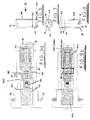
- the exemplary chain tensioner has a housing body 10 that is designed to be inserted into a threaded bore 11 defined in an internal combustion engine cylinder block 12 (shown in figure 3).
- the body 10 has, at one end, a head 13 with a plurality of flats F for engagement with an appropriate fastening tool (not shown) and an adjacent threaded portion 14 by which the tensioner is screw-engaged in the bore 11.
- the tensioner body 10 is generally cylindrical and has a blind bore 15 that is open at one end to receive a slidable hollow plunger 16.
- the exposed end 17 of the plunger 15 is closed except for a small central outlet vent 18 and defines a channel 19 for abutment with a complementary formation on the underside of a movable blade (not shown) that supports a chain guide or shoe (not shown).
- the interior of the bore 15 is divided into two chambers by a check valve assembly comprising a ball check valve 20 and support 21.
- a check valve assembly comprising a ball check valve 20 and support 21.
- the plunger 16 and bore 15 define a variable volume chamber 22 that is filled with hydraulic oil.
- the bore 15 defines an oil reservoir 23 that supplies oil to the chamber 22 via the ball check valve 20.
- the oil reservoir 23 is in turn supplied with oil from the vehicle engine oil supply via a radial inlet passage 24 that is designed as a throttle to limit the pressure of the oil in the reservoir.
- the reservoir 23 ensures that there is sufficient oil available at engine start-up (when the engine oil pressure is low) for the tensioner to work effectively.
- vent 18 Access to the vent 18 from inside the chamber 22 is restricted by a venting plug 26 of known design so as to limit the escape of air and oil.
- a compression spring 27 is disposed coaxially between the closed end 17 of the plunger 16 and the base of the housing bore 15 (for clarity only part of spring is shown in the figures) and serves to bias the plunger 16 outwards of the housing body 1 towards the chain so as to impart tension thereto.
- a ratchet locking mechanism 28 Interposed between the plunger 16 and the compression spring 27 there is provided a ratchet locking mechanism 28 of known configuration that is designed to prevent excessive retraction of the plunger 16 even when the fluid pressure is low.
- the mechanism is embodied by a cylinder 29 with a helical toothed slot in which a peg 30 on the plunger 16 is engaged in step-wise fashion.
- An annular seal 31 is provided adjacent to the head 13 so as to seal the tensioner in the threaded bore 11 in the engine cylinder block 12 in the manner shown in figure 3.
- the plunger 16 and housing bore 15 are dimensioned so as to be a close fit such that relative reciprocal movement is permitted but oil in the chamber is prevented from leaking out between them.
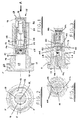
- the outside surface of the plunger 16 has a pattern of V-section grooves defined thereon as can be seen in figures 1 and 3 to 10.
- First and second grooves 40, 41 of the pattern are circumferential and located towards the open end of the plunger. They are spaced apart and joined by a third groove 42 that extends in the axial direction (i.e. parallel to the longitudinal axis of the plunger) to the open end of the plunger 16.
- Fourth and fifth grooves 43, 44 also extend in the axial direction but are disposed diametrically opposite to the third groove 42.
- the fourth groove 43 extends from the open end of the plunger to a position where it meets the first circumferential groove 40 and the fifth groove 44 extends from the second circumferential groove 41 to the closed end 17 of the plunger 16.
- the grooves are designed to allow air trapped in the oil chamber 22 to escape and are of a depth that permits air to flow easily but prevents any significant oil flow in view of its greater viscosity in comparison to air. Since air is less dense than the oil it tends to collect at the top of the chamber adjacent to the third groove 42.
- the axial grooves 42, 43, 44 are arranged to have a predetermined orientation with respect to the channel 19 on the closed end of the plunger 16. This ensures that when the tensioner is fitted to the engine block 11 the grooves 40-44 are positioned to ensure effective and efficient air purging.
- the plunger 16 is rotated in the bore 15 to bring the channel 19 into the correct orientation to receive the formation on the underside of the blade.
- either the third or fourth groove 42, 43 (both of which extend from the open end of the plunger 16) is at the top of the oil chamber 22 and occupies a vertical plane (illustrated by line V-V in figure 5) that intersects the longitudinal axis of the tensioner.
- One such orientation is shown in figure 9a.
- tensioner bore may be inclined slightly to the horizontal so that the head end 13 of the tensioner is disposed slightly above the closed end 17 of the plunger 16. This encourages the air in the oil chamber 22 to collect at the top left so that the air purge action is expedited.
- the ratio of the oil passage 24 are to the outlet area of the groove is designed to be around 3.3 or more.
- the groove or grooves may be formed by laser machining, milling or broaching.
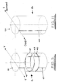
- FIG 11 An alternative simplified embodiment of the plunger is illustrated schematically in figure 11 in which there is provided a single groove 100 along the outside of the plunger 116 extending in parallel with the longitudinal axis thereof.
- the tensioner plunger is unidirectional in that the groove 100 must be oriented upwards so as to ensure effective air purging.
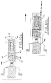
- Figures 12 and 13 show alternative embodiments of the invention with different oil inlet designs.
- the oil inlet is a nozzle 124 that is press-fitted into a radial bore in the tensioner housing and in the embodiment of figure 13 the inlet is provided by a plug 224 with an external screw formation 245.
- the air purge groove formations may be defined on the inside surface of the tensioner housing adjacent to the plunger as opposed to being on the plunger itself.
Applications Claiming Priority (2)
| Application Number | Priority Date | Filing Date | Title |
|---|---|---|---|
| GBGB0316575.0A GB0316575D0 (en) | 2003-07-16 | 2003-07-16 | Tensioner for a chain or belt |
| GB0316575 | 2003-07-16 |
Publications (3)
| Publication Number | Publication Date |
|---|---|
| EP1498580A2 true EP1498580A2 (fr) | 2005-01-19 |
| EP1498580A3 EP1498580A3 (fr) | 2006-05-31 |
| EP1498580B1 EP1498580B1 (fr) | 2009-03-11 |
Family
ID=27763881
Family Applications (1)
| Application Number | Title | Priority Date | Filing Date |
|---|---|---|---|
| EP04254162A Not-in-force EP1498580B1 (fr) | 2003-07-16 | 2004-07-13 | Tendeur pour chaîne ou courroie |
Country Status (5)
| Country | Link |
|---|---|
| US (1) | US7331891B2 (fr) |
| EP (1) | EP1498580B1 (fr) |
| AT (1) | ATE425347T1 (fr) |
| DE (1) | DE602004019845D1 (fr) |
| GB (1) | GB0316575D0 (fr) |
Cited By (2)
| Publication number | Priority date | Publication date | Assignee | Title |
|---|---|---|---|---|
| US8062157B2 (en) | 2007-10-30 | 2011-11-22 | Iwis Motorsysteme Gmbh & Co. Kg | Tensioner with an adjuster |
| US8905877B2 (en) | 2010-10-28 | 2014-12-09 | Schaeffler Technologies AG & Co. KG | Tensioning device with a cylindrical latching system |
Families Citing this family (13)
| Publication number | Priority date | Publication date | Assignee | Title |
|---|---|---|---|---|
| GB0515176D0 (en) * | 2005-07-23 | 2005-08-31 | Renold Plc | Transmission chain monitoring system |
| US20070032322A1 (en) * | 2005-08-05 | 2007-02-08 | Beardmore John M | Hydraulic chain tensioner assembly |
| GB0607775D0 (en) * | 2006-04-20 | 2006-05-31 | Renold Plc | Tensioner for a chain or belt |
| DE102007000750A1 (de) * | 2007-09-20 | 2009-04-09 | Hilti Aktiengesellschaft | Handwerkzeugmaschine mit Riemenspannvorrichtung |
| JP5250889B2 (ja) * | 2008-10-01 | 2013-07-31 | 日本発條株式会社 | テンショナー |
| EP2458246B1 (fr) * | 2010-11-29 | 2013-10-02 | iwis motorsysteme GmbH & Co. KG | Dispositif de serrage doté d'un dispositif d'évaporation comprenant un volume de réception minimal |
| DE102011013374A1 (de) * | 2011-03-09 | 2012-09-13 | Iwis Motorsysteme Gmbh & Co. Kg | Spannvorrichtung mit mindestens zwei Entlüftungselementen |
| DE102012219281A1 (de) * | 2012-10-23 | 2014-04-24 | Schaeffler Technologies Gmbh & Co. Kg | Zugmittelspanner |
| DE102013219073A1 (de) * | 2013-09-23 | 2015-03-26 | Schaeffler Technologies Gmbh & Co. Kg | Spannvorrichtung mit einer Entlüftungseinheit |
| JP6182411B2 (ja) * | 2013-09-26 | 2017-08-16 | Ntn株式会社 | 油圧式オートテンショナ |
| JP6448983B2 (ja) * | 2014-10-29 | 2019-01-09 | 株式会社椿本チエイン | テンショナ |
| JP7041349B2 (ja) * | 2018-05-28 | 2022-03-24 | 株式会社椿本チエイン | テンショナ |
| CN113758715B (zh) * | 2021-08-30 | 2024-02-23 | 重庆长安汽车股份有限公司 | 一种发动机柱塞式张紧器的异响位置确定方法 |
Citations (5)
| Publication number | Priority date | Publication date | Assignee | Title |
|---|---|---|---|---|
| EP0348861A2 (fr) * | 1988-07-01 | 1990-01-03 | Eaton Corporation | Tendeur de chaîne à actionnement hydraulique |
| DE4103055A1 (de) * | 1991-02-01 | 1992-08-06 | Schaeffler Waelzlager Kg | Hydraulisches spielausgleichselement fuer den einsatz von brennkraftmaschinen |
| EP1067275A2 (fr) * | 1999-07-06 | 2001-01-10 | Borg-Warner Automotive K. K. | Tendeur de chaíne hydraulique avec dispositif directionnel de décharge d'air |
| US20010003279A1 (en) * | 1999-12-10 | 2001-06-14 | Bayerische Motoren Werke Aktiengesellschaft | Chain drive of a V-engine having overhead camshafts |
| EP1227264A1 (fr) * | 2001-01-25 | 2002-07-31 | Tsubakimoto Chain Co. | Tendeur hydraulique avec verrouillage à cliquet |
Family Cites Families (12)
| Publication number | Priority date | Publication date | Assignee | Title |
|---|---|---|---|---|
| DE3145115C2 (de) | 1981-11-13 | 1983-12-08 | Dr.Ing.H.C. F. Porsche Ag, 7000 Stuttgart | "Hydraulischer Kettenspanner" |
| DE3832512C1 (en) * | 1988-09-24 | 1990-04-26 | Bayerische Motoren Werke Ag, 8000 Muenchen, De | Tensioning device for an endless flexible transmission |
| JPH0550214U (ja) * | 1991-12-12 | 1993-07-02 | 株式会社椿本チエイン | オイルによって空気侵入経路をシールしたオイル作動式テンショナ |
| US5370584A (en) | 1993-01-15 | 1994-12-06 | Borg-Warner Automotive, Inc. | Piston design for removing air from a hydraulic tensioner |
| JPH07280049A (ja) | 1994-04-12 | 1995-10-27 | Tsubakimoto Chain Co | 摺動面に螺旋状溝を設けたオイル式テンショナ |
| JPH102386A (ja) * | 1996-06-13 | 1998-01-06 | Tsubakimoto Chain Co | 緩衝機構付ラチェット式テンショナ |
| JPH1038043A (ja) * | 1996-07-26 | 1998-02-13 | Tsubakimoto Chain Co | 油圧式テンショナ |
| JP3635198B2 (ja) | 1997-12-22 | 2005-04-06 | Ntn株式会社 | チェーンテンショナ |
| JPH11201245A (ja) | 1998-01-12 | 1999-07-27 | Ntn Corp | チェーンテンショナ |
| US6126563A (en) * | 1998-09-21 | 2000-10-03 | Borgwarner Inc. | Quick purge tensioner with internal piston spring |
| US6053831A (en) * | 1998-12-08 | 2000-04-25 | Borg-Warner Automotive, Inc. | Hydraulic tensioner with passage of variable cross-section between the piston and bore |
| DE10155364A1 (de) * | 2001-11-10 | 2003-05-22 | Bayerische Motoren Werke Ag | Hydraulische Spannvorrichtung für ein Zugmittelgetriebe, insbesondere Ketten- oder Riementriebe von Brennkraftmaschinen |
-
2003
- 2003-07-16 GB GBGB0316575.0A patent/GB0316575D0/en not_active Ceased
-
2004
- 2004-07-07 US US10/886,429 patent/US7331891B2/en not_active Expired - Fee Related
- 2004-07-13 DE DE602004019845T patent/DE602004019845D1/de active Active
- 2004-07-13 AT AT04254162T patent/ATE425347T1/de not_active IP Right Cessation
- 2004-07-13 EP EP04254162A patent/EP1498580B1/fr not_active Not-in-force
Patent Citations (5)
| Publication number | Priority date | Publication date | Assignee | Title |
|---|---|---|---|---|
| EP0348861A2 (fr) * | 1988-07-01 | 1990-01-03 | Eaton Corporation | Tendeur de chaîne à actionnement hydraulique |
| DE4103055A1 (de) * | 1991-02-01 | 1992-08-06 | Schaeffler Waelzlager Kg | Hydraulisches spielausgleichselement fuer den einsatz von brennkraftmaschinen |
| EP1067275A2 (fr) * | 1999-07-06 | 2001-01-10 | Borg-Warner Automotive K. K. | Tendeur de chaíne hydraulique avec dispositif directionnel de décharge d'air |
| US20010003279A1 (en) * | 1999-12-10 | 2001-06-14 | Bayerische Motoren Werke Aktiengesellschaft | Chain drive of a V-engine having overhead camshafts |
| EP1227264A1 (fr) * | 2001-01-25 | 2002-07-31 | Tsubakimoto Chain Co. | Tendeur hydraulique avec verrouillage à cliquet |
Cited By (2)
| Publication number | Priority date | Publication date | Assignee | Title |
|---|---|---|---|---|
| US8062157B2 (en) | 2007-10-30 | 2011-11-22 | Iwis Motorsysteme Gmbh & Co. Kg | Tensioner with an adjuster |
| US8905877B2 (en) | 2010-10-28 | 2014-12-09 | Schaeffler Technologies AG & Co. KG | Tensioning device with a cylindrical latching system |
Also Published As
| Publication number | Publication date |
|---|---|
| US20050059517A1 (en) | 2005-03-17 |
| ATE425347T1 (de) | 2009-03-15 |
| EP1498580A3 (fr) | 2006-05-31 |
| GB0316575D0 (en) | 2003-08-20 |
| DE602004019845D1 (de) | 2009-04-23 |
| US7331891B2 (en) | 2008-02-19 |
| EP1498580B1 (fr) | 2009-03-11 |
Similar Documents
| Publication | Publication Date | Title |
|---|---|---|
| EP1406029B1 (fr) | Dispositif tendeur hydraulique pour chaînes | |
| EP1602857B1 (fr) | Tendeur hydraulique | |
| EP1498580B1 (fr) | Tendeur pour chaîne ou courroie | |
| EP0989333B1 (fr) | Tendeur hydraulique avec verrouillage à cliquet externe | |
| EP2532923B1 (fr) | Cathéter pour commande antimicrobienne et son procédé de fabrication | |
| US7641575B2 (en) | Hydraulic tensioner | |
| JP6378661B2 (ja) | チェーンテンショナ | |
| US6244982B1 (en) | Hydraulic chain tensioner with a piston having a plurality of sliding elements | |
| EP1653121B1 (fr) | Tendeur de chaîne | |
| JP3670911B2 (ja) | チェーンテンショナ | |
| US20090111628A1 (en) | Tensioner for a chain or belt | |
| US8007384B2 (en) | Hydraulic tensioner | |
| US7427250B2 (en) | Ring type hydraulic tensioner | |
| JP2001304360A (ja) | 液圧チェーンテンショナ | |
| US20060166769A1 (en) | Hydraulic chain tensioner | |
| EP2267335B1 (fr) | Tendeur de chaîne | |
| US8033938B2 (en) | Hydraulic tensioner | |
| EP1698803A1 (fr) | Tendeur de chaine | |
| EP1528286B1 (fr) | Tendeur hydraulique | |
| US20080096707A1 (en) | Chain tensioner | |
| EP1215415B1 (fr) | Dispositif tendeur pour un élément souple sans fin | |
| WO2021014471A1 (fr) | Tendeur hydraulique pour distribution de charge uniforme |
Legal Events
| Date | Code | Title | Description |
|---|---|---|---|
| PUAI | Public reference made under article 153(3) epc to a published international application that has entered the european phase |
Free format text: ORIGINAL CODE: 0009012 |
|
| AK | Designated contracting states |
Kind code of ref document: A2 Designated state(s): AT BE BG CH CY CZ DE DK EE ES FI FR GB GR HU IE IT LI LU MC NL PL PT RO SE SI SK TR |
|
| AX | Request for extension of the european patent |
Extension state: AL HR LT LV MK |
|
| PUAL | Search report despatched |
Free format text: ORIGINAL CODE: 0009013 |
|
| AK | Designated contracting states |
Kind code of ref document: A3 Designated state(s): AT BE BG CH CY CZ DE DK EE ES FI FR GB GR HU IE IT LI LU MC NL PL PT RO SE SI SK TR |
|
| AX | Request for extension of the european patent |
Extension state: AL HR LT LV MK |
|
| 17P | Request for examination filed |
Effective date: 20060704 |
|
| 17Q | First examination report despatched |
Effective date: 20060914 |
|
| AKX | Designation fees paid |
Designated state(s): AT BE BG CH CY CZ DE DK EE ES FI FR GB GR HU IE IT LI LU MC NL PL PT RO SE SI SK TR |
|
| RAP1 | Party data changed (applicant data changed or rights of an application transferred) |
Owner name: SCHAEFFLER CHAIN DRIVE SYSTEMS SAS |
|
| GRAP | Despatch of communication of intention to grant a patent |
Free format text: ORIGINAL CODE: EPIDOSNIGR1 |
|
| GRAS | Grant fee paid |
Free format text: ORIGINAL CODE: EPIDOSNIGR3 |
|
| GRAA | (expected) grant |
Free format text: ORIGINAL CODE: 0009210 |
|
| AK | Designated contracting states |
Kind code of ref document: B1 Designated state(s): AT BE BG CH CY CZ DE DK EE ES FI FR GB GR HU IE IT LI LU MC NL PL PT RO SE SI SK TR |
|
| REG | Reference to a national code |
Ref country code: GB Ref legal event code: FG4D |
|
| REG | Reference to a national code |
Ref country code: CH Ref legal event code: EP |
|
| REG | Reference to a national code |
Ref country code: IE Ref legal event code: FG4D |
|
| REF | Corresponds to: |
Ref document number: 602004019845 Country of ref document: DE Date of ref document: 20090423 Kind code of ref document: P |
|
| PG25 | Lapsed in a contracting state [announced via postgrant information from national office to epo] |
Ref country code: NL Free format text: LAPSE BECAUSE OF FAILURE TO SUBMIT A TRANSLATION OF THE DESCRIPTION OR TO PAY THE FEE WITHIN THE PRESCRIBED TIME-LIMIT Effective date: 20090311 Ref country code: FI Free format text: LAPSE BECAUSE OF FAILURE TO SUBMIT A TRANSLATION OF THE DESCRIPTION OR TO PAY THE FEE WITHIN THE PRESCRIBED TIME-LIMIT Effective date: 20090311 Ref country code: SI Free format text: LAPSE BECAUSE OF FAILURE TO SUBMIT A TRANSLATION OF THE DESCRIPTION OR TO PAY THE FEE WITHIN THE PRESCRIBED TIME-LIMIT Effective date: 20090311 |
|
| NLV1 | Nl: lapsed or annulled due to failure to fulfill the requirements of art. 29p and 29m of the patents act | ||
| PG25 | Lapsed in a contracting state [announced via postgrant information from national office to epo] |
Ref country code: PL Free format text: LAPSE BECAUSE OF FAILURE TO SUBMIT A TRANSLATION OF THE DESCRIPTION OR TO PAY THE FEE WITHIN THE PRESCRIBED TIME-LIMIT Effective date: 20090311 Ref country code: SE Free format text: LAPSE BECAUSE OF FAILURE TO SUBMIT A TRANSLATION OF THE DESCRIPTION OR TO PAY THE FEE WITHIN THE PRESCRIBED TIME-LIMIT Effective date: 20090611 Ref country code: AT Free format text: LAPSE BECAUSE OF FAILURE TO SUBMIT A TRANSLATION OF THE DESCRIPTION OR TO PAY THE FEE WITHIN THE PRESCRIBED TIME-LIMIT Effective date: 20090311 |
|
| PG25 | Lapsed in a contracting state [announced via postgrant information from national office to epo] |
Ref country code: BE Free format text: LAPSE BECAUSE OF FAILURE TO SUBMIT A TRANSLATION OF THE DESCRIPTION OR TO PAY THE FEE WITHIN THE PRESCRIBED TIME-LIMIT Effective date: 20090311 |
|
| PG25 | Lapsed in a contracting state [announced via postgrant information from national office to epo] |
Ref country code: PT Free format text: LAPSE BECAUSE OF FAILURE TO SUBMIT A TRANSLATION OF THE DESCRIPTION OR TO PAY THE FEE WITHIN THE PRESCRIBED TIME-LIMIT Effective date: 20090824 Ref country code: EE Free format text: LAPSE BECAUSE OF FAILURE TO SUBMIT A TRANSLATION OF THE DESCRIPTION OR TO PAY THE FEE WITHIN THE PRESCRIBED TIME-LIMIT Effective date: 20090311 Ref country code: CZ Free format text: LAPSE BECAUSE OF FAILURE TO SUBMIT A TRANSLATION OF THE DESCRIPTION OR TO PAY THE FEE WITHIN THE PRESCRIBED TIME-LIMIT Effective date: 20090311 Ref country code: ES Free format text: LAPSE BECAUSE OF FAILURE TO SUBMIT A TRANSLATION OF THE DESCRIPTION OR TO PAY THE FEE WITHIN THE PRESCRIBED TIME-LIMIT Effective date: 20090622 |
|
| PG25 | Lapsed in a contracting state [announced via postgrant information from national office to epo] |
Ref country code: SK Free format text: LAPSE BECAUSE OF FAILURE TO SUBMIT A TRANSLATION OF THE DESCRIPTION OR TO PAY THE FEE WITHIN THE PRESCRIBED TIME-LIMIT Effective date: 20090311 Ref country code: RO Free format text: LAPSE BECAUSE OF FAILURE TO SUBMIT A TRANSLATION OF THE DESCRIPTION OR TO PAY THE FEE WITHIN THE PRESCRIBED TIME-LIMIT Effective date: 20090311 |
|
| REG | Reference to a national code |
Ref country code: FR Ref legal event code: TP |
|
| PLBE | No opposition filed within time limit |
Free format text: ORIGINAL CODE: 0009261 |
|
| STAA | Information on the status of an ep patent application or granted ep patent |
Free format text: STATUS: NO OPPOSITION FILED WITHIN TIME LIMIT |
|
| PG25 | Lapsed in a contracting state [announced via postgrant information from national office to epo] |
Ref country code: BG Free format text: LAPSE BECAUSE OF FAILURE TO SUBMIT A TRANSLATION OF THE DESCRIPTION OR TO PAY THE FEE WITHIN THE PRESCRIBED TIME-LIMIT Effective date: 20090611 Ref country code: DK Free format text: LAPSE BECAUSE OF FAILURE TO SUBMIT A TRANSLATION OF THE DESCRIPTION OR TO PAY THE FEE WITHIN THE PRESCRIBED TIME-LIMIT Effective date: 20090311 |
|
| 26N | No opposition filed |
Effective date: 20091214 |
|
| PG25 | Lapsed in a contracting state [announced via postgrant information from national office to epo] |
Ref country code: MC Free format text: LAPSE BECAUSE OF NON-PAYMENT OF DUE FEES Effective date: 20090731 |
|
| REG | Reference to a national code |
Ref country code: CH Ref legal event code: PL |
|
| GBPC | Gb: european patent ceased through non-payment of renewal fee |
Effective date: 20090713 |
|
| PG25 | Lapsed in a contracting state [announced via postgrant information from national office to epo] |
Ref country code: LI Free format text: LAPSE BECAUSE OF NON-PAYMENT OF DUE FEES Effective date: 20090731 Ref country code: CH Free format text: LAPSE BECAUSE OF NON-PAYMENT OF DUE FEES Effective date: 20090731 |
|
| PG25 | Lapsed in a contracting state [announced via postgrant information from national office to epo] |
Ref country code: GB Free format text: LAPSE BECAUSE OF NON-PAYMENT OF DUE FEES Effective date: 20090713 |
|
| PG25 | Lapsed in a contracting state [announced via postgrant information from national office to epo] |
Ref country code: IE Free format text: LAPSE BECAUSE OF NON-PAYMENT OF DUE FEES Effective date: 20090713 |
|
| PG25 | Lapsed in a contracting state [announced via postgrant information from national office to epo] |
Ref country code: GR Free format text: LAPSE BECAUSE OF FAILURE TO SUBMIT A TRANSLATION OF THE DESCRIPTION OR TO PAY THE FEE WITHIN THE PRESCRIBED TIME-LIMIT Effective date: 20090612 |
|
| PG25 | Lapsed in a contracting state [announced via postgrant information from national office to epo] |
Ref country code: IT Free format text: LAPSE BECAUSE OF FAILURE TO SUBMIT A TRANSLATION OF THE DESCRIPTION OR TO PAY THE FEE WITHIN THE PRESCRIBED TIME-LIMIT Effective date: 20090311 |
|
| PG25 | Lapsed in a contracting state [announced via postgrant information from national office to epo] |
Ref country code: LU Free format text: LAPSE BECAUSE OF NON-PAYMENT OF DUE FEES Effective date: 20090713 |
|
| PG25 | Lapsed in a contracting state [announced via postgrant information from national office to epo] |
Ref country code: HU Free format text: LAPSE BECAUSE OF FAILURE TO SUBMIT A TRANSLATION OF THE DESCRIPTION OR TO PAY THE FEE WITHIN THE PRESCRIBED TIME-LIMIT Effective date: 20090912 |
|
| PG25 | Lapsed in a contracting state [announced via postgrant information from national office to epo] |
Ref country code: TR Free format text: LAPSE BECAUSE OF FAILURE TO SUBMIT A TRANSLATION OF THE DESCRIPTION OR TO PAY THE FEE WITHIN THE PRESCRIBED TIME-LIMIT Effective date: 20090311 |
|
| PG25 | Lapsed in a contracting state [announced via postgrant information from national office to epo] |
Ref country code: CY Free format text: LAPSE BECAUSE OF FAILURE TO SUBMIT A TRANSLATION OF THE DESCRIPTION OR TO PAY THE FEE WITHIN THE PRESCRIBED TIME-LIMIT Effective date: 20090311 |
|
| PGFP | Annual fee paid to national office [announced via postgrant information from national office to epo] |
Ref country code: FR Payment date: 20140731 Year of fee payment: 11 |
|
| PGFP | Annual fee paid to national office [announced via postgrant information from national office to epo] |
Ref country code: DE Payment date: 20140930 Year of fee payment: 11 |
|
| REG | Reference to a national code |
Ref country code: DE Ref legal event code: R119 Ref document number: 602004019845 Country of ref document: DE |
|
| PG25 | Lapsed in a contracting state [announced via postgrant information from national office to epo] |
Ref country code: DE Free format text: LAPSE BECAUSE OF NON-PAYMENT OF DUE FEES Effective date: 20160202 |
|
| REG | Reference to a national code |
Ref country code: FR Ref legal event code: ST Effective date: 20160331 |
|
| PG25 | Lapsed in a contracting state [announced via postgrant information from national office to epo] |
Ref country code: FR Free format text: LAPSE BECAUSE OF NON-PAYMENT OF DUE FEES Effective date: 20150731 |
|
| P01 | Opt-out of the competence of the unified patent court (upc) registered |
Effective date: 20230522 |