EP1498576A1 - Drilling device for earth drill - Google Patents
Drilling device for earth drill Download PDFInfo
- Publication number
- EP1498576A1 EP1498576A1 EP02722785A EP02722785A EP1498576A1 EP 1498576 A1 EP1498576 A1 EP 1498576A1 EP 02722785 A EP02722785 A EP 02722785A EP 02722785 A EP02722785 A EP 02722785A EP 1498576 A1 EP1498576 A1 EP 1498576A1
- Authority
- EP
- European Patent Office
- Prior art keywords
- inner member
- excavating tool
- excavating
- locking element
- bucket
- Prior art date
- Legal status (The legal status is an assumption and is not a legal conclusion. Google has not performed a legal analysis and makes no representation as to the accuracy of the status listed.)
- Granted
Links
Images


Classifications
-
- E—FIXED CONSTRUCTIONS
- E21—EARTH DRILLING; MINING
- E21B—EARTH DRILLING, e.g. DEEP DRILLING; OBTAINING OIL, GAS, WATER, SOLUBLE OR MELTABLE MATERIALS OR A SLURRY OF MINERALS FROM WELLS
- E21B7/00—Special methods or apparatus for drilling
- E21B7/02—Drilling rigs characterized by means for land transport with their own drive, e.g. skid mounting or wheel mounting
-
- E—FIXED CONSTRUCTIONS
- E02—HYDRAULIC ENGINEERING; FOUNDATIONS; SOIL SHIFTING
- E02F—DREDGING; SOIL-SHIFTING
- E02F3/00—Dredgers; Soil-shifting machines
- E02F3/04—Dredgers; Soil-shifting machines mechanically-driven
- E02F3/46—Dredgers; Soil-shifting machines mechanically-driven with reciprocating digging or scraping elements moved by cables or hoisting ropes ; Drives or control devices therefor
- E02F3/47—Dredgers; Soil-shifting machines mechanically-driven with reciprocating digging or scraping elements moved by cables or hoisting ropes ; Drives or control devices therefor with grab buckets
-
- E—FIXED CONSTRUCTIONS
- E21—EARTH DRILLING; MINING
- E21B—EARTH DRILLING, e.g. DEEP DRILLING; OBTAINING OIL, GAS, WATER, SOLUBLE OR MELTABLE MATERIALS OR A SLURRY OF MINERALS FROM WELLS
- E21B7/00—Special methods or apparatus for drilling
- E21B7/003—Drilling with mechanical conveying means
Abstract
Description
- The present invention relates to an excavating tool mounted at the kelly bar of an earth drill to excavate cobblestones, boulders, concrete slab or the like.
- An earth drill, which excavates material by taking in excavated soil into a bucket while excavating the bottom of a bore hole with a cutter provided at a conical bottom cover, is normally ideal for an excavating operation on a soil stratum that can be represented with an N value. However, it is not suited for so-called barrier excavation including excavation of stones such as cobblestones and boulders that are too large to fit into the drilling bucket and excavation of a concrete slab. If the cutter strikes such a layer during an excavating operation, special measures must be taken by, for instance, removing the cobblestones with a hammer grab bucket mounted at a separate crane or using an all casing machine.
- The inventor of the present invention et al. proposed in Japanese Unexamined Patent Publication No. H 11-141261 a means for solving the problem described above, achieved by mounting a detachable cylindrical bucket at the kelly bar instead of the drilling bucket for the earth drill having the bottom cover and by also providing a auger type excavating tool that forms a small hole in the vicinity of its circular drilling groove to allow excavated material to be drawn out through the hole.
- However, there is a problem with an earth drill that utilizes a cylindrical bucket as disclosed in Japanese Unexamined Patent Publication No. H 11-141261 in that a separate lifting means is required to lift the excavated round slab, rocks and the like.
- Accordingly, the inventor of the present invention et al. proposed an excavating tool for an earth drill in Japanese Unexamined Patent Publication No. 2001-90465, which allows excavated material to be lifted to the ground level during a barrier excavating operation of slab, cobblestones, boulders or the like executed with the earth drill.
- The excavating tool disclosed in the publication described above comprises an inner member having an upper end thereof connected to the kelly bar, an outer member and a second member provided between the inner member and the outer member. These members are combined so as to allow them to move up/down relative to one another. In addition, a cylindrical bracket having an cutting teeth at the lower end thereof and an open bottom is mounted at the outer member. At the outer member, a grab bucket housed inside the cylindrical bucket and constituted of a pair of jaws which grab objects excavated with the cylindrical bucket is provided as well.
- The lower end of the second member is linked to the jaws at the grab bucket so as to open and close the grab bucket. The excavating tool adopts a structure that closes the grab bucket as the second member moves upward relative to the outer member and opens the grab bucket as the second member moves downward relative to the outer member. Namely, the inner member and the second member are connected with each other through a first hydraulic cylinder and second hydraulic cylinders provided between the second member and the grab bucket. Pressure is generated as the kelly bar is lifted and the first hydraulic cylinder consequently extends, which communicates the pressure to the second hydraulic cylinders to extend the second hydraulic cylinder. This lifts the second member relative to the outer member, and thus, the grab bucket mounted at the outer member closes to trap soil.
- The excavating tool adopts a structure that automatically releases the binds among the inner member, the second member and the outer member achieved with cotters to allow them to extend as the members held in a most contained state achieved with the cotters are lowered to the bottom of the bore hole. Then, as the kelly bar is rotated, the cylindrical bucket and the grab bucket are caused to rotate together with the inner member, the second member and the outer member to cut into the earth. When the kelly bar is lifted after the earth is cut to a predetermined depth, the inner member is lifted together with the kelly bar while the outer member remains at the bottom of the bore hole due to the dead weight of the cylindrical bucket, the grab bucket and the like. As a result, the grab bucket, with its jaws linked to the second member, closes through the operation described above to take in the soil to be excavated. After the grab bucket is closed, the outer member is lifted to the ground level together with the cylindrical bucket and the grab bucket. As the cylindrical bucket is set on the ground and the kelly bar is lowered, the first hydraulic cylinder contracts, the pressure generated in the pressure oil through the contraction of the first hydraulic cylinder causes the second hydraulic cylinders to contract as well and the second member is lowered as a result, thereby allowing the grab bucket to open to discharge the excavated soil onto the ground.
- The excavating tool for an earth drill disclosed in Japanese Unexamined Patent Publication No. 2001-90465 described above is yet to address the following problems.
- (1) This excavating tool executes excavation while a load representing the sum of the dead weight of the excavating tool and the pressing force of the kelly bar achieved by setting the cylindrical bucket on the excavating surface in a state in which the grab bucket is open and then by pushing down the kelly bar. However, the level of the load that can be applied to the excavating surface while the grab bucket is open becomes equal to or greater than the load of the excavating tool and thus, the pressing force constituted of a load less than that of the excavating tool cannot be applied. To explain this in more specific terms, as the excavating tool is lowered to the bottom of the bore hole, the cotter mounted at the outer member becomes automatically disengaged from the hole of the second member and the hole of the inner member, and if the kelly bar is lifted in this state, the inner member becomes also lifted relative to the second member and the second member, too, becomes lifted relative to the outer member, thereby closing the grab bucket. For this reason, the excavating operation may become difficult if an earth drill with a small drive force is utilized to rotate a cylindrical bucket with a large diameter, since a large excavating torque is required due to the increase in the resistance at the excavating surface, the dead weight of the large excavating tool and the like.
- (2) In addition, since the pressing force cannot be controlled so as not to exceed the dead weight of the excavating tool, the cutter mounted at the lower end of the outer member may become damaged readily.
- (3) Japanese Unexamined Patent Publication No. 2001-90465 described above discloses in one of the embodiments a structure detailed below. Namely, in a state in which the excavating tool is at its most contracted, a projection formed at the outer circumference of the inner member becomes engaged at a notch formed at the sleeve of the second member, thereby preventing the relative vertical movement among the members so as to allow the grab bucket to be lifted while it is open. However, there is a problem with this structure in that if there is a relatively large underground obstacle such as a rock, the underground obstacle cannot be removed by closing the jaws to a certain extent and rotating the underground obstacle grabbed with the jaws.
-
- An object of the present invention is to provide an excavating tool for an earth drill having a cylindrical bucket with a grab bucket provided therein which is closed by using the force with which the kelly bar is lifted, which allows an excavating operation to be executed while a load smaller than the load of the excavating tool is applied, thereby enabling an earth drill with a small drive force to excavate material with a relatively large excavating tool and makes it possible to remove underground obstacles by rotating the grab bucket in a state in which the grab bucket is partially closed.
- (1) In order to achieve the object described above, the excavating tool for an earth drill according to the present invention comprises a tubular inner member linked to the kelly bar, a tubular second member fitted on the outer side of the inner member so as to be allowed to move up/down freely and an outer member should on the outer side of the second member so as to be allowed to move up/down. A cylindrical bucket and a grab bucket housed inside the cylindrical bucket are mounted at the outer member, a first hydraulic cylinder is mounted between the inner member and the second member, second hydraulic cylinders which are caused to extend or contract by pressure oil from the first hydraulic cylinder are mounted between the second member and the jaws of the grab bucket, and a locking mechanism is provided between the inner member and the outer member. The locking mechanism is constituted of a locking element provided at the outer circumference of the inner member and a locking element bearing plate provided at the top of the outer member, the locking element is allowed to pass through the locking element bearing plate when the inner member and the outer member achieve a specific relative rotational angle, and the locking element is locked at the locking element bearing plate to disallow relative vertical movement of the inner member and the outer member as the inner member is rotated along the forward direction when the excavating tool is in the most contracted state. A projection provided at the outer circumference of the inner member is fitted in guide rails provided along the longitudinal direction at the inner circumference of the second member so as to be allowed to move up/down freely, and the inner member is allowed to rotate forward over a predetermined range relative to the second member when the excavating tool is in the most contracted state. Since the locking mechanism that disallows the relative vertical movement of the inner member and the outer member when the excavating tool is in the most contracted state is provided as described above, an excavating operation can be executed while a load smaller than the load of the excavating tool is applied by the cylindrical bucket to the excavating surface by applying a certain level of force to the kelly bar along the lifting direction to rotate the kelly bar along the forward rotating direction, i.e., along the excavating direction. As a result, even when excavating material by using a small earth drill to rotationally drive a relatively large excavating tool, a sufficient drive force is assured for the excavating operation. In addition, the excavating operation can be executed in an optimal manner with a small pressing force as called for in specific individual situations.Furthermore, even if there is an excessively large lifting reactive force when the grab bucket is operated along the closing direction at the bottom of the bore hole, the grab bucket can still be lifted in an open state by lowering the inner member again, rotating the kelly bar by a predetermined angle along the forward direction and locking the locking element at the locking element bearing plate. Thus, the risk of not being able to lift the excavating tool out of the ground under such circumstances is eliminated.Since the second member and the outer member can be caused to rotate reciprocally by interlocking with the rotation of the inner member as the kelly bar rotates while the inner member is in a state in which it is lifted to a certain extent relative to the second member and the outer member, i.e., in a state in which the grab bucket is in the process of becoming closed, an underground obstacle clamped at the grab bucket can be rotated to more easily remove the underground obstacle compared to the related art.
- (2) It is desirable that excavating tool for an earth drill according to the present invention include the locking element at the top of the inner member formed as a cylindrical portion, that the locking element include a projecting portion projecting outward as an integrated part of a disk having a diameter larger than the diameter of the cylindrical portion and that the locking element bearing plate be constituted of a plate having a locking element passing portion which is substantially isomorphic with the locking element and slightly larger than the locking element. By constituting the locking element and the locking element bearing plate with plates larger than the cylindrical portion as described above, the locking element and the locking element bearing plate are placed in contact with each other over a large area when they are in a locked state so as to withstand a large load.
- (3) In addition, it is desirable that the inner member in the excavating tool for an earth drill according to the present invention include a cylindrical portion the outer circumferential surface of which comes in contact with the guide rails located at a corner of an angular tube portion within the second member and bracing rails provided at the inner surfaces of the angular tube portion. By placing the outer circumferential surface of the cylindrical inner member in contact with the guide rails and the bracing rails as described above, the inner member does not become off-centered relative to the second member or the outer member so as to ensure that the locking element is allowed to pass through the locking element passing portion of the locking element bearing plate smoothly.
- (4) It is also desirable that the excavating tool for an earth drill according to the present invention further include third hydraulic cylinders that match the volumes of supply/discharge oil quantities between the first hydraulic cylinder and the second hydraulic cylinders. By providing the third hydraulic cylinders as a dummy cylinders, it becomes unnecessary to mount an accumulator and the like at the excavating tool and, at the same time, a structure having the bottom chambers of the hydraulic cylinders turned upward can be adopted. As a result, the closed hydraulic circuit can be formed by using hydraulic piping constituted of steel instead of hydraulic hose.
-
-
- FIG. 1 is a side elevation of an earth drill having an excavating tool as achieved in an embodiment of the present invention;
- FIG. 2 is a side elevation of the excavating tool in FIG. 1 in its most contracted state;
- FIG. 3 is a cross-section of a side elevation of the excavating tool in FIG. 2 in its most extended state;
- FIG. 4 is a plan view of the top of the excavating tool in FIG. 2;
- FIG. 5 is a plan view of the top of the excavating tool in FIG. 3;
- FIG. 6 is a sectional view taken along E-E in FIG. 2;
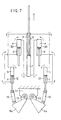
- FIG. 7 shows the structures of the hydraulic cylinders constituting an grab drive device for the grab bucket achieved in the embodiment;
- FIG. 8 is a side elevation of the outer member achieved in the embodiment;
- FIG. 9 is a front view of the outer member in FIG. 8;
- FIG. 10 is a plan view of the top of the outer member achieved in the embodiment;
- FIGS. 11 and 12 present sectional views taken along F-F and G-G respectively in FIG. 8;
- FIG. 13 is a front view of the second member achieved in the embodiment;
- FIG. 14 is a bottom view of the second member in FIG. 13;
- FIG. 15 is a side elevation of the second member achieved in the embodiment;
- FIG. 16 is a sectional view taken along D-D in FIG. 15;
- FIG. 17 is a plan view of the first member constituting the inner member achieved in the embodiment;
- FIG. 18 is a cutaway side elevation of the first member shown in FIG. 17;
- FIG. 19 is a sectional view taken along H-H in FIG. 18;
- FIG. 20 is a plan view of the second member constituting the inner member in the embodiment;
- FIG. 21 is a side elevation of the second member shown in FIG. 20;
- FIG. 22 is a bottom view of FIG. 20;
- FIG. 23 is a side elevation of a structure that allows the inner member and the second member to be set in combination with each other during a forward rotation when the excavating tool in the embodiment is in the most contracted state;
- FIG. 24 is a sectional view taken along I-I in FIG. 23;
- FIG. 25 is a side elevation of a structure that allows the inner member and the second member to be set in combination with each other during a reverse rotation when the excavating tool in the embodiment is in the most contracted state;
- FIG. 26 is a sectional view taken along J-J in FIG. 25;
- FIG. 27 is a side elevation of a structure that allows the inner member and the second member to be set in combination with each other when the grab bucket is in a half closed state in the excavating tool in the embodiment; and
- FIG. 28 is a sectional view taken along K-K in FIG. 27.
-
- FIG. 1 is a side elevation of an earth drill having the excavating tool according to the present invention as achieved in an embodiment. As shown in FIG. 1, a
boom 51 is mounted at an earth drillmain unit 50 so as to be freely raised or lowered with hoistinggear 52 and afront frame 53 is mounted at the front of the earth drillmain unit 50 so as to be freely raised and lowered with thehoisting gear 54. At the top of thefront frame 53, akelly drive device 56 that rotates a kelly bar 1 inserted through thekelly drive device 56 so as to allow the kelly bar to move up/down is installed. The kelly bar 1 is supported via a swivel joint 59 with a hoistingrope 58 which is taken up and fed by a hoistwinch 57 mounted at the earth drillmain unit 50. The kelly bar 1 is constituted by fitting together three or more pipes of various sizes so as to allow them to move up/down but disallow their rotation relative to each other, with a drilling bucket linked to the innermost pipe. Reference numeral 2 indicates the excavating tool according to the present invention, which is detachably mounted at the kelly bar 1 for barrier excavation instead of the drilling bucket that is normally mounted at the kelly bar 1. - FIG. 2 is a side elevation of the excavating tool 2 in its most contracted state, i.e., in a state in which the grab bucket is open, FIG. 3 is a cross section of a side elevation of the excavating tool 2 in its most extended state, i.e., in a state in which the grab bucket is closed, FIGS. 4 and 5 are plan views of the top sides of FIGS. 2 and 3 respectively, FIG. 6 is a sectional view taken along E-E in FIG. 2 and FIG. 7 shows the structure of the hydraulic cylinders constituting an grab drive device for the grab bucket.
- In FIGS. 2 to 7,
reference numeral 3 indicates an inner member which is detachably connected to the kelly bar 1 with a pin 4 (see FIG. 1),reference numeral 5 indicates a second member which is fitted on the outer side of theinner member 3 so as to be allowed to move up/down freely andreference numeral 6 indicates an outer member which is fitted on the outer side of the second member so as to be allowed to move up/down freely. Acylindrical bucket 7 is mounted at theouter member 6 and thegrab bucket 8 is mounted inside thecylindrical bucket 7. - FIG. 8 is a side elevation of the
outer member 6, FIG. 9 is a front view of theouter member 6, FIG. 10 is a plan view of the top side of theouter member 6 and FIGS. 11 and 12 are sectional views taken along F-F and G-G in FIG. 8 respectively. - As shown in FIGS. 8, 9 and 11, the
outer member 6 includes anangular tube portion 6i having part of its side surface removed and located at the center of theouter member 6. At the front and rear surfaces of theangular cube portion 6i, mountingplates 6a each constituted of a parallel plate are bonded and thecylindrical bucket 7 is bonded to the lower portions of the mountingplates 6a. As shown in FIGS. 2 and 3, a plurality of cuttingteeth 7a are disposed along the circumferential direction at the lower portion of thecylindrical bucket 7. - As shown in FIGS. 2 and 3, a first
hydraulic cylinder 9 is housed inside theinner member 3, the piston rod of the firsthydraulic cylinder 9 is connected to theinner member 3 with apin 10 and the bottom side of the firsthydraulic cylinder 9 is connected to thesecond member 5 with apin 11. - FIG. 13 is a front view of the
second member 5, FIG. 14 is a bottom view of thesecond member 5, FIG. 15 is a side elevation of thesecond member 5 and FIG. 16 is a plan view of thesecond member 5. In FIGS. 13 to 15,reference numeral 5n indicates an angular tube portion provided at the center of thesecond member 5, which is fitted inside theangular tube portion 6i of theouter member 6 so as to be allowed to move up/down without allowing theangular tube portions 6i to rotate relative to each other.Reference numeral 5a indicates a pin hole formed at thesecond member 5 at which thepin 11 is inserted. As theinner member 3 is lifted together with the kelly bar 1, the firsthydraulic cylinder 9 extends by stretching relative to thesecond member 5 and, as a result, pressure oil is supplied to secondhydraulic cylinders 12 provided to grab thegrab bucket 8. - The second
hydraulic cylinders 12 are mounted atbrackets 5b (see FIGS. 13 to 15) provided to the front and to the rear of theangular tube portion 5n of thesecond member 5 and atbrackets 6j (see FIG. 12) provided at the cylindrical bucket mountingparallel plates 6a located to the front and to the rear of theouter member 6 viapins Reference numeral 5c in FIGS. 13 to 15 andreference numeral 6c in FIGS. 8 and 12 respectively indicate pin holes at which thepins - As shown in FIGS. 13 to 15, mounting
plates 5d are bonded to the left and right sides of theangular tube portion 5n at thesecond member 5.Brackets 5f are mounted at the front ends of these mountingplates 5a*[1]. Eachbracket 5f includespin hole 5e through which a pin 15 (see FIGS. 2 and 3) is inserted to rotatably connect a pivotal connecting portion located on the upper inner side of ajaw 8a of thegrab bucket 8. - As shown in FIGS. 2 and 3, each
bracket 6b at theouter member 6 and the central portion of thecorresponding jaw 8a are rotatably linked vialinks 16 and pins 17 and 19.Reference numeral 6d in FIGS. 8, 9 and 12 indicates a pin hole through which thepin 17 is inserted. - As shown in FIG. 7, third
hydraulic cylinders 20 are provided on one side of the hydraulic circuit between the firsthydraulic cylinders 9 and the secondhydraulic cylinders 12. The thirdhydraulic cylinders 20 constitute a dummy hydraulic cylinder having the function of matching the supply/discharge oil quantities between thehydraulic cylinders hydraulic cylinders 20 eliminates the need to mount an accumulator and the like at the excavating tool. In addition, since a structure having the piston rod side of the firsthydraulic cylinder 9 turned upward and the bottom chambers of the secondhydraulic cylinders 12 turned upward can be adopted, a closed hydraulic circuit can be formed with hydraulic piping constituted of steel instead of hydraulic hose. As shown in FIGS. 2, 4, 5, 8, 9 and 11, the thirdhydraulic cylinders 20 are mounted by pinning their upper ends tobrackets 6h provided atribs 6e constituted of parallel plates at theouter member 6. - As shown in FIG. 6, the
inner member 3 is constituted of afirst member 3A and asecond member 3B. FIGS. 17 through 19 shows thefirst member 3A which includes alocking element 3d assuming the shape of a disk larger than acylindrical portion 3c and located above thecylindrical portion 3c. Thelocking element 3d includes a plurality of projectingportions 3e projecting outward and formed along the outer circumference. Thefirst member 3A also includes a connectingportion 3f assuming an angular tube shape, which connects with the kelly bar 1 and is located above thelocking element 3d, and apin hole 3g through which thepin 4 is inserted to mount thefirst member 3A at the kelly bar 1 is formed at the connectingportion 3f. - FIGS. 20 through 22 show the
second member 3B which includes alocking element 3j isomorphic with thelocking element 3d, having projectingportions 3i similar to those of thelocking element 3d, assuming the shape of a disk with an area larger than the area of acylindrical portion 3h and located at the top of thecylindrical portion 3h. In addition, inside thecylindrical portion 3h, acylindrical element 23, which supports a connectingpiece 22 of thepin 10 at the firsthydraulic cylinder 9 is fastened. As shown in FIGS. 3 and 6, thefirst member 3A and thesecond member 3B are fastened to each other with afastening piece 24 by fitting theircylindrical portions locking elements fastening piece 25 by placing each projectingportion 3e in alignment with a projectingportion 3i. - As shown in FIGS. 21 and 22, at the bottom of the
second member 3B,projections 3k are provided at two positions facing opposite each other. As shown in FIGS. 23 and 24, at theangular tube portion 5n of thesecond member 5,guide rails 5j extending along the longitudinal direction and each constituted of tworods angular tube portion 5n of thesecond member 5, bracingrails 5p which, together with theguide rails 5j, come in contact with the outer circumferential surface of thecylindrical portion 3h of theinner member 3 are provided. At two side surfaces of thesecond member 5 facing opposite each other,openings 5k at which theprojections 3k are fitted are provided, withstoppers 5m provided along the edges of theopenings 5k. As shown in FIG. 23, of the tworods guide rails 5j, the lower end of therod 5h located closer to theopening 5k is set at a height H1 substantially level with the upper side of theopening 5k, whereas the lower end of therod 5i located further away from theopening 5k is set at a height H2 substantially level with the lower side of theopening 5k. - As shown in FIGS. 4, 5 and 10, at the top of the
outer member 6, a lockingelement bearing plate 6f constituted of a plate having a lockingelement passing portion 6g substantially isomorphic with thelocking elements locking elements element passing portion 6g includes dentedportions 6j (may be grooves) in correspondence to the projectingportions projections 3k of theinner member 3 fitted at theguide rails 5j, the projectingportions locking elements portions 6j of the lockingelement passing portion 6g, as shown in FIG. 5, and thus, thelocking elements element passing portion 6g. Since the outer circumferential surface of thecylindrical portion 3h of theinner member 3 is placed in contact with theguide rails 5j and the bracingrails 5p, theinner member 3 does not become off-centered relative to thesecond member 5 and theouter member 6, and as a result, thelocking elements element passing portion 6g smoothly without play. - When the
inner member 3 is at the lowest position relative to theouter member 6, i.e., when the excavating tool is in the most contracted state, theprojections 3k of theinner member 3 are set lower than the bottom ends of therods 5h, as shown in FIG. 23, and thus, as theinner member 3 is caused to rotate forward together with the kelly bar 1 (as theinner member 3 rotates along the excavating direction), theinner member 3 rotates forward relative to thesecond member 5 and theouter member 6, thereby allowing theprojections 3k to slip out of theopenings 5k to come in contact with thestoppers 5m. As theinner member 3 is made to rotate forward in this manner, the projectingportions locking elements element bearing plate 6f as shown in FIG. 4, and thus, theouter member 6 can be lifted together with theinner member 3 by lifting the kelly bar 1. By constituting thelocking elements element bearing plate 6f with plates larger in size than thecylindrical portions locking elements element bearing plate 6f are allowed to achieve contact with the lockingelement bearing plate 6f over large areas so as to withstand a large load. - Next, the operation of the excavating tool is explained. After the soil is discharged overground, the
grab bucket 8 is in an open state, and as the kelly bar 1 is rotated forward with thecylindrical bucket 7 set on the ground in this state, thelocking elements element bearing plate 6f as shown in FIG. 4. The excavating tool 2 is then hoisted into the bore hole 30 (see FIG. 1). - As the
cylindrical bucket 7 of the excavating tool 2 is set onto the bottom surface of thebore hole 30, thekelly drive device 56 is activated to rotate the excavating tool 2 along the forward direction via the kelly bar 1. As a result, theprojections 3k of theinner member 3 come into contact with thestoppers 5m of thesecond member 5. In addition, the projectingportions locking elements element bearing plate 6f of theouter member 6. The rotational force of the kelly bar 1 is communicated to thecylindrical bucket 7 in this state, thereby causing thecylindrical bucket 7 to rotate and allowing thecylindrical bucket 7 to excavate a slab, cobblestones or boulders. - Such an excavating operation can be executed with a load smaller than the load of the excavating tool 2 applied to the excavating surface by operating the hoist
winch 57 slightly along the lifting direction to apply a slight force to the kelly bar 1 along the lifting direction and thus rotating the kelly bar 1 along the forward direction, i.e., along the excavating direction. As a result, even when the excavating operation is executed by rotationally driving a relatively large excavating tool 2 with a small earth drill, the operation can be executed with a small pressing force. Thus, a sufficient drive force is assured in the excavating operation. In addition, even if there is an excessively large excavating reactive force, the excavating operation can be executed with an optimal pressing force. It goes without saying that depending upon the situation, the excavating operation can be executed with a pressing force equal to or greater than the load of the excavating tool 2 and the like by holding the kelly bar 1 downward with a pressing device (not shown) provided at thekelly drive device 56. - As the excavating operation executed with the
cylindrical bucket 7 progresses and excavated material is collected in thecylindrical bucket 7 in a quantity suitable to be taken into thegrab bucket 8, theinner member 3 is rotated in reverse together with the kelly bar 1. This reverse rotation places theprojections 3k of theinner member 3 each in contact with one of the rods, i.e., therod 5i constituting aguide rail 5j, as shown in FIGS. 25 and 26. - Then, the
inner member 3 is lifted together with the kelly bar 1 in the state shown in FIGS. 25 and 26. In this situation, since the loads of theouter member 6, thecylindrical bucket 7 and thegrab bucket 8 are applied to thesecond member 5, the firsthydraulic cylinder 9 is first allowed to extend. As the firsthydraulic cylinder 9 extends as described above, the oil in a rod chamber a of the firsthydraulic cylinder 9 becomes pressurized to become pressure oil which then enters bottom chambers b at the tops of the secondhydraulic cylinders 12, as indicated by the arrows in FIG. 7. In addition, the oil in rod chambers c of the secondhydraulic cylinders 12 enters rod chambers d of the thirdhydraulic cylinders 20, whereas the oil in the bottom chambers e of the thirdhydraulic cylinders 20 enters a bottom chamber f of the firsthydraulic cylinder 9. - As the oil flows as described above, the second
hydraulic cylinders 12 extend, which causes thesecond member 5 to move upward. As a result, the opposite ends of thejaws 8a connected via thepins 15 with thebrackets 5f fastened to thesecond member 5 become lifted, thereby closing thegrab bucket 8, as shown in FIG. 3 to allow it to grab the excavated material. It is to be noted that if a slab is being excavated, thegrab bucket 8 grabs the slab drilled in a disk shape at its edge, and thus, thegrab bucket 8 does not close as completely. - As described above, the force with which the kelly bar 1 is lifted can be used to close the
grab bucket 8 and, as a result, a high level of closing force can be obtained by using the hoisting force of the hoistwinch 57. - In this structure, the second
hydraulic cylinders 12 and the thirdhydraulic cylinders 20 function as a booster that compensates for the difference between the supply and discharge quantities of oil attributable to the difference in the sectional areas of the rod chamber a and the bottom chamber f of the firsthydraulic cylinder 9. Thus, a closed circuit can be constituted without having to employ an accumulator. - After the excavated material is grabbed in the
grab bucket 8 as described above, the kelly bar 1 is lifted together with the excavating tool 2 by the hoistwinch 57. After the excavating tool 2 having been lifted to the ground level is set on the ground surface, the kelly bar 1 is lowered to allow the oil to flow in the direction opposite from that indicated by the arrows in FIG. 7, thereby causing the firsthydraulic cylinder 9 to contract, as shown in FIG. 2. As a result, the secondhydraulic cylinders 12 also contract to open thegrab bucket 8 to discharge the excavated material in thegrab bucket 8. - During the operation described above, if the lifting reactive force generated at the bottom of the bore hole is too large relative to the force applied to close the
grab bucket 8, thegrab bucket 8 can be lifted in an open state by lowering theinner member 3 again, rotating the kelly bar forward by a specific angle and locking thelocking elements element bearing plate 6f. Thus, the excavating tool can be lifted from underground even under such circumstances. - Also, as shown in FIGS. 27and 28, when the
inner member 3 is lifted to a certain extent relative to thesecond member 5 and theouter member 6, i.e., when thegrab bucket 8 is undergoing the process of becoming closed, theprojections 3k of theinner member 3 are clamped between therods guide rails 5j. If theinner member 3 is rotated together with the kelly bar 1 in this state, thesecond member 5 and theouter member 6, too, can be rotated forward and back by interlocking with the rotation of theinner member 3. Thus, by rotating them while an underground obstacle is held in thegrab bucket 8, the underground obstacle can be handled with greater ease than in the related art. - The present invention may also be adopted in a structure having a cylindrical add-on excavating tool with cutting teeth, which is detachably mounted at the lower end of the
cylindrical bucket 7 with a fastening piece such as a bolt, as described in Japanese Unexamined Patent Publication No. 2001-90465. By adopting the structure, it becomes possible to execute the excavating operation in an optimal manner at all times by selecting an excavating tool having an optimal depth and an optimal function for a given excavating site from various add-on excavating tools with varying heights and varying types of cutting teeth. - In addition, the present invention may be implemented without the third
hydraulic cylinders 20 by, for instance, reversing the top side and the bottom side of the secondhydraulic cylinders 12. Also, the present invention may be adopted in an earth drill having a structure in which the kelly drive device is moved up/down along a leader. Moreover, theinner member 3 may have a single cylinder structure instead of the double cylinder structure. - The excavating tool for an earth drill according to the present invention, having a grab bucket provided inside a cylindrical bucket and the grab bucket is caused to close by the force with which the kelly bar is lifted, allows the locking elements of the inner member to be locked at the locking element bearing plate of the outer member while the excavating tool is in its most contracted state. As a result, an excavating operation can be executed while a load smaller than the load of the excavating tool is applied. Thus, an earth drill with a small drive force is able to perform an excavating operation with a relatively large bucket. In addition, whenever the situation calls for it, an ideal excavating operation can be executed with a small pressing force. Since it adopts the structure having the guide rails at the second member at which the projections formed at the outer circumference of the inner member become held so as to be allowed to move up/down freely, it is possible to rotate the grab bucket while it is closed to a certain extent, and consequently, underground obstacles can be removed with ease in a manner appropriate to a given situation.
Claims (4)
- An excavating tool for an earth drill, characterized in that;
comprising a tubular inner member (3) connected to a kelly bar (1), a tubular second member (5) fitted on the outer side of said inner member (3) so as to be allowed to move up/down freely and an outer member (6) fitted on the outer side of said second member (5) so as to be allowed to move up/down freely:a cylindrical bucket (7) and a grab bucket (8) housed in side said cylindrical bucket (7) are mounted at said outer member (6);a first hydraulic cylinder (9) is mounted between said inner member (3) and said second member (5), and second hydraulic cylinders (12) which are caused to extend/contract by the pressure oil from said first hydraulic cylinder (9) are mounted between said second member (5) and jaws (8a) of said grab bucket (8);a locking mechanism is provided between said inner member (3) and said outer member (6), said locking mechanism is constituted of locking elements (3d, 3j) provided at the outer circumference of said inner member (3) and a locking element bearing plate (6f) provided at the upper portion of said outer member (6), said locking elements (3d, 3j) are allowed to pass through said locking element bearing plate (6f) when said inner member (3) and said outer member (6) achieve a specific relative rotational angle and said locking elements (3d, 3j) become locked at said locking element bearing plate (6f) to disallow relative vertical movement of said inner member (3) and said outer member (6) by rotating said inner member (3) forward when said excavating tool (2) is in a most contracted state; andprojections (3k) provided at the outer circumference of said inner member (3) are fitted at guide rails (5j) extending along the longitudinal direction at the inner circumference of said second member (5) so as to be allowed to move up/down freely, and said inner member (3) is allowed to rotate forward relative to said second member (5) within a predetermined range when said excavating tool (2) is in the most contracted state. - An excavating tool (2) for an earth drill according to claim 1, characterized in that:said inner member (3) includes said locking elements (3d, 3j) above cylindrical portions (3c, 3h);said locking elements (3d, 3j) respectively include projecting portions (3e, 3i) projecting outward as integrated portions of disks having diameters larger than the diameters of said cylindrical portions (3c, 3h); andsaid locking element bearing plate (6f) is constituted of a plate having a locking element passing portion (6g) substantially isomorphic with said locking elements (3d, 3j) and slightly larger than said locking elements (3d, 3j).
- An excavating tool (2) for an earth drill according to claim 1 or 2, characterized in that:said inner member (3) includes a cylindrical portion (3h); andthe outer circumferential surface of said cylindrical portion (3h) is in contact with said guide rails (5j) provided at corners of an angular tube portion (5n) inside said second member (5) and bracing rails (5p) provided at the inner surface of said angular tube portion (5n).
- An excavating tool (2) for an earth drill according to any of claims 1 through 3, characterized in that:third hydraulic cylinders (20) that match supply/discharge oil quantities between said first hydraulic cylinder (9) and said second hydraulic cylinders (12) are provided in a closed hydraulic circuit located between said first hydraulic cylinder (9) and said second hydraulic cylinders (12).
Applications Claiming Priority (1)
| Application Number | Priority Date | Filing Date | Title |
|---|---|---|---|
| PCT/JP2002/004143 WO2003091532A1 (en) | 2002-04-25 | 2002-04-25 | Drilling device for earth drill |
Publications (3)
| Publication Number | Publication Date |
|---|---|
| EP1498576A1 true EP1498576A1 (en) | 2005-01-19 |
| EP1498576A4 EP1498576A4 (en) | 2006-05-10 |
| EP1498576B1 EP1498576B1 (en) | 2007-12-26 |
Family
ID=29267258
Family Applications (1)
| Application Number | Title | Priority Date | Filing Date |
|---|---|---|---|
| EP02722785A Expired - Lifetime EP1498576B1 (en) | 2002-04-25 | 2002-04-25 | Drilling device for earth drill |
Country Status (7)
| Country | Link |
|---|---|
| US (1) | US7032692B2 (en) |
| EP (1) | EP1498576B1 (en) |
| JP (1) | JP3818519B2 (en) |
| KR (1) | KR100539630B1 (en) |
| CN (1) | CN1297725C (en) |
| DE (1) | DE60224306T2 (en) |
| WO (1) | WO2003091532A1 (en) |
Families Citing this family (12)
| Publication number | Priority date | Publication date | Assignee | Title |
|---|---|---|---|---|
| WO2006120581A2 (en) * | 2005-04-29 | 2006-11-16 | Nelson Alvarez Arzayus | Digger for piles |
| CA2903524C (en) * | 2011-07-14 | 2017-12-19 | Halliburton Energy Services, Inc. | Methods and systems for controlling torque transfer from rotating equipment |
| US9027217B2 (en) | 2011-07-26 | 2015-05-12 | Triple C Rig Welding, Llc | Blowout preventer head removal tools and methods |
| JP5892970B2 (en) * | 2013-04-09 | 2016-03-23 | 株式会社エーコー | Drilling system |
| JP6247940B2 (en) * | 2014-01-22 | 2017-12-13 | 日本車輌製造株式会社 | Earth drill machine |
| JP6329382B2 (en) * | 2014-02-14 | 2018-05-23 | 正記 ▲高▼田 | Excavation bucket and excavation method |
| US10174476B2 (en) * | 2014-03-17 | 2019-01-08 | Cong Ty Tnhh Phy Cuong | Grab bucket of an auger |
| JP6387503B2 (en) * | 2014-05-28 | 2018-09-12 | システム計測株式会社 | Bucket equipment |
| DE102017004270A1 (en) * | 2017-05-03 | 2018-11-08 | Liebherr-Werk Nenzing Gmbh | Diaphragm wall grab with hybrid drive |
| CN107605439B (en) * | 2017-10-16 | 2019-08-23 | 东北石油大学 | A kind of crude oil bailing platform |
| JP7004981B2 (en) * | 2018-07-06 | 2022-01-21 | 株式会社丸建興業 | Bucket device for earth drill |
| NL1043302B1 (en) * | 2019-06-17 | 2021-01-25 | Magali Shachar | Tubular drive assembly |
Family Cites Families (13)
| Publication number | Priority date | Publication date | Assignee | Title |
|---|---|---|---|---|
| US2122584A (en) * | 1936-08-01 | 1938-07-05 | Benjamin E Bertran | Undercutting bucket |
| US3194329A (en) * | 1964-06-11 | 1965-07-13 | Calweld Inc | Hydraulic grab bucket |
| FR2618483B1 (en) * | 1987-07-23 | 1989-12-15 | Sorenam | DRILLING MACHINE BY ROTATION AND BY VOVOIEMENT |
| US4971163A (en) * | 1989-09-12 | 1990-11-20 | Kabushiki Kaisha Konoike Gumi | Drilling bucket apparatus for cast-in-place piles with expanded bottoms |
| US5067570A (en) * | 1990-08-31 | 1991-11-26 | Gilcrease John T | Auger and retaining shell assembly |
| JPH0768840B2 (en) * | 1992-06-16 | 1995-07-26 | 丸五基礎工業株式会社 | Bottomless lid drilling bucket |
| IT1270436B (en) * | 1993-06-09 | 1997-05-05 | Trevi Spa | PERFORATION TOOL FOR THE REALIZATION OF LARGE DIAMETER STONES IN ROCK, VENTILATION WELLS AND OTHER SIMILAR EXCAVATION WORKS |
| JPH11141261A (en) | 1997-11-11 | 1999-05-25 | Hitachi Constr Mach Co Ltd | Earth drill device and digging construction method for batholith |
| JP4079558B2 (en) * | 1999-09-21 | 2008-04-23 | 株式会社播州建機 | Earth drilling tool and earth drill |
| JP2001152776A (en) * | 1999-11-30 | 2001-06-05 | Mitsubishi Heavy Ind Ltd | Shaft excavator |
| JP3665533B2 (en) * | 2000-05-18 | 2005-06-29 | 株式会社 北斗工業 | Hammer grab cover device |
| JP3922435B2 (en) * | 2001-07-09 | 2007-05-30 | カトウ建機有限会社 | Drilling bucket for earth drill |
| JP3856739B2 (en) * | 2002-07-25 | 2006-12-13 | 三和機工株式会社 | Drilling bucket for earth drill |
-
2002
- 2002-04-25 WO PCT/JP2002/004143 patent/WO2003091532A1/en active IP Right Grant
- 2002-04-25 JP JP2003588047A patent/JP3818519B2/en not_active Expired - Fee Related
- 2002-04-25 EP EP02722785A patent/EP1498576B1/en not_active Expired - Lifetime
- 2002-04-25 CN CNB028145674A patent/CN1297725C/en not_active Expired - Fee Related
- 2002-04-25 KR KR10-2004-7000170A patent/KR100539630B1/en not_active IP Right Cessation
- 2002-04-25 DE DE60224306T patent/DE60224306T2/en not_active Expired - Lifetime
- 2002-04-25 US US10/481,010 patent/US7032692B2/en not_active Expired - Fee Related
Non-Patent Citations (2)
| Title |
|---|
| No further relevant documents disclosed * |
| See also references of WO03091532A1 * |
Also Published As
| Publication number | Publication date |
|---|---|
| US7032692B2 (en) | 2006-04-25 |
| EP1498576A4 (en) | 2006-05-10 |
| DE60224306D1 (en) | 2008-02-07 |
| US20040168831A1 (en) | 2004-09-02 |
| EP1498576B1 (en) | 2007-12-26 |
| KR20040030792A (en) | 2004-04-09 |
| WO2003091532A1 (en) | 2003-11-06 |
| CN1533464A (en) | 2004-09-29 |
| KR100539630B1 (en) | 2005-12-28 |
| DE60224306T2 (en) | 2009-01-08 |
| JP3818519B2 (en) | 2006-09-06 |
| CN1297725C (en) | 2007-01-31 |
| JPWO2003091532A1 (en) | 2005-09-02 |
Similar Documents
| Publication | Publication Date | Title |
|---|---|---|
| US6540443B2 (en) | Apparatus for and a method of boring the ground | |
| US3645343A (en) | Rotary drilling machine | |
| EP1498576B1 (en) | Drilling device for earth drill | |
| US10145193B2 (en) | Axially separating drill bucket | |
| JP6886717B2 (en) | Construction method of steel pipe pile | |
| JP6308990B2 (en) | Attachment for removing underground obstacles and method for removing underground obstacles | |
| JPS6320996B1 (en) | ||
| KR20210007555A (en) | Rock splitting system of non-vibration and anti-noise, and continuous rock splitting method using the same | |
| JP4526085B2 (en) | Underground pile cutting equipment | |
| JP3594758B2 (en) | Existing structure recovery method and existing structure recovery device using all casing method | |
| JP2019094612A (en) | Hydraulic excavation work machine | |
| JP2007291807A (en) | Foundation machine and method for attaching and removing shaft body | |
| JP4079558B2 (en) | Earth drilling tool and earth drill | |
| JP2001323767A (en) | Pit excavator | |
| JP4272591B2 (en) | Shaft excavator | |
| JP4920352B2 (en) | Drilling rig | |
| JP3576721B2 (en) | Earth drill machine | |
| KR100479514B1 (en) | Apparatus for and a method of boring the ground | |
| US3143229A (en) | Excavators | |
| JP3037609B2 (en) | Drilling rig | |
| JP4105322B2 (en) | Pile driving method and pile driving device | |
| KR101986648B1 (en) | Excavating device for steel pipe access hole | |
| JP2002201887A (en) | Excavator | |
| JP3749868B2 (en) | Steel pipe pile construction method | |
| JP2004060186A (en) | Excavating bucket for earth drill |
Legal Events
| Date | Code | Title | Description |
|---|---|---|---|
| PUAI | Public reference made under article 153(3) epc to a published international application that has entered the european phase |
Free format text: ORIGINAL CODE: 0009012 |
|
| 17P | Request for examination filed |
Effective date: 20041116 |
|
| AK | Designated contracting states |
Kind code of ref document: A1 Designated state(s): DE IT |
|
| A4 | Supplementary search report drawn up and despatched |
Effective date: 20060323 |
|
| GRAP | Despatch of communication of intention to grant a patent |
Free format text: ORIGINAL CODE: EPIDOSNIGR1 |
|
| GRAS | Grant fee paid |
Free format text: ORIGINAL CODE: EPIDOSNIGR3 |
|
| GRAA | (expected) grant |
Free format text: ORIGINAL CODE: 0009210 |
|
| AK | Designated contracting states |
Kind code of ref document: B1 Designated state(s): DE IT |
|
| REF | Corresponds to: |
Ref document number: 60224306 Country of ref document: DE Date of ref document: 20080207 Kind code of ref document: P |
|
| PG25 | Lapsed in a contracting state [announced via postgrant information from national office to epo] |
Ref country code: DE Free format text: LAPSE BECAUSE OF FAILURE TO SUBMIT A TRANSLATION OF THE DESCRIPTION OR TO PAY THE FEE WITHIN THE PRESCRIBED TIME-LIMIT Effective date: 20080327 |
|
| PLBE | No opposition filed within time limit |
Free format text: ORIGINAL CODE: 0009261 |
|
| STAA | Information on the status of an ep patent application or granted ep patent |
Free format text: STATUS: NO OPPOSITION FILED WITHIN TIME LIMIT |
|
| 26N | No opposition filed |
Effective date: 20080929 |
|
| PGFP | Annual fee paid to national office [announced via postgrant information from national office to epo] |
Ref country code: DE Payment date: 20120502 Year of fee payment: 11 |
|
| PGFP | Annual fee paid to national office [announced via postgrant information from national office to epo] |
Ref country code: IT Payment date: 20120421 Year of fee payment: 11 |
|
| PG25 | Lapsed in a contracting state [announced via postgrant information from national office to epo] |
Ref country code: DE Free format text: LAPSE BECAUSE OF FAILURE TO SUBMIT A TRANSLATION OF THE DESCRIPTION OR TO PAY THE FEE WITHIN THE PRESCRIBED TIME-LIMIT Effective date: 20131101 |
|
| REG | Reference to a national code |
Ref country code: DE Ref legal event code: R119 Ref document number: 60224306 Country of ref document: DE Effective date: 20131101 |
|
| PG25 | Lapsed in a contracting state [announced via postgrant information from national office to epo] |
Ref country code: IT Free format text: LAPSE BECAUSE OF NON-PAYMENT OF DUE FEES Effective date: 20130425 |