EP1498563A1 - Device for providing a ventilation gap - Google Patents
Device for providing a ventilation gap Download PDFInfo
- Publication number
- EP1498563A1 EP1498563A1 EP04007489A EP04007489A EP1498563A1 EP 1498563 A1 EP1498563 A1 EP 1498563A1 EP 04007489 A EP04007489 A EP 04007489A EP 04007489 A EP04007489 A EP 04007489A EP 1498563 A1 EP1498563 A1 EP 1498563A1
- Authority
- EP
- European Patent Office
- Prior art keywords
- spring
- gap
- latching
- wing
- fitting part
- Prior art date
- Legal status (The legal status is an assumption and is not a legal conclusion. Google has not performed a legal analysis and makes no representation as to the accuracy of the status listed.)
- Granted
Links
Images


Classifications
-
- E—FIXED CONSTRUCTIONS
- E05—LOCKS; KEYS; WINDOW OR DOOR FITTINGS; SAFES
- E05C—BOLTS OR FASTENING DEVICES FOR WINGS, SPECIALLY FOR DOORS OR WINDOWS
- E05C17/00—Devices for holding wings open; Devices for limiting opening of wings or for holding wings open by a movable member extending between frame and wing; Braking devices, stops or buffers, combined therewith
- E05C17/02—Devices for holding wings open; Devices for limiting opening of wings or for holding wings open by a movable member extending between frame and wing; Braking devices, stops or buffers, combined therewith by mechanical means
- E05C17/04—Devices for holding wings open; Devices for limiting opening of wings or for holding wings open by a movable member extending between frame and wing; Braking devices, stops or buffers, combined therewith by mechanical means with a movable bar or equivalent member extending between frame and wing
- E05C17/12—Devices for holding wings open; Devices for limiting opening of wings or for holding wings open by a movable member extending between frame and wing; Braking devices, stops or buffers, combined therewith by mechanical means with a movable bar or equivalent member extending between frame and wing consisting of a single rod
- E05C17/24—Devices for holding wings open; Devices for limiting opening of wings or for holding wings open by a movable member extending between frame and wing; Braking devices, stops or buffers, combined therewith by mechanical means with a movable bar or equivalent member extending between frame and wing consisting of a single rod pivoted at one end, and with the other end running along a guide member
-
- E—FIXED CONSTRUCTIONS
- E05—LOCKS; KEYS; WINDOW OR DOOR FITTINGS; SAFES
- E05C—BOLTS OR FASTENING DEVICES FOR WINGS, SPECIALLY FOR DOORS OR WINDOWS
- E05C17/00—Devices for holding wings open; Devices for limiting opening of wings or for holding wings open by a movable member extending between frame and wing; Braking devices, stops or buffers, combined therewith
- E05C17/02—Devices for holding wings open; Devices for limiting opening of wings or for holding wings open by a movable member extending between frame and wing; Braking devices, stops or buffers, combined therewith by mechanical means
- E05C17/04—Devices for holding wings open; Devices for limiting opening of wings or for holding wings open by a movable member extending between frame and wing; Braking devices, stops or buffers, combined therewith by mechanical means with a movable bar or equivalent member extending between frame and wing
- E05C17/08—Devices for holding wings open; Devices for limiting opening of wings or for holding wings open by a movable member extending between frame and wing; Braking devices, stops or buffers, combined therewith by mechanical means with a movable bar or equivalent member extending between frame and wing with special means for release, e.g. automatic release by further opening
-
- E—FIXED CONSTRUCTIONS
- E05—LOCKS; KEYS; WINDOW OR DOOR FITTINGS; SAFES
- E05C—BOLTS OR FASTENING DEVICES FOR WINGS, SPECIALLY FOR DOORS OR WINDOWS
- E05C17/00—Devices for holding wings open; Devices for limiting opening of wings or for holding wings open by a movable member extending between frame and wing; Braking devices, stops or buffers, combined therewith
- E05C17/02—Devices for holding wings open; Devices for limiting opening of wings or for holding wings open by a movable member extending between frame and wing; Braking devices, stops or buffers, combined therewith by mechanical means
- E05C17/46—Devices for holding wings open; Devices for limiting opening of wings or for holding wings open by a movable member extending between frame and wing; Braking devices, stops or buffers, combined therewith by mechanical means in which the wing or a member fixed thereon is engaged by a movable fastening member in a fixed position; in which a movable fastening member mounted on the wing engages a stationary member
- E05C17/52—Devices for holding wings open; Devices for limiting opening of wings or for holding wings open by a movable member extending between frame and wing; Braking devices, stops or buffers, combined therewith by mechanical means in which the wing or a member fixed thereon is engaged by a movable fastening member in a fixed position; in which a movable fastening member mounted on the wing engages a stationary member comprising a snap, catch, or the like
-
- E—FIXED CONSTRUCTIONS
- E05—LOCKS; KEYS; WINDOW OR DOOR FITTINGS; SAFES
- E05D—HINGES OR SUSPENSION DEVICES FOR DOORS, WINDOWS OR WINGS
- E05D15/00—Suspension arrangements for wings
- E05D15/48—Suspension arrangements for wings allowing alternative movements
- E05D15/52—Suspension arrangements for wings allowing alternative movements for opening about a vertical as well as a horizontal axis
- E05D15/5205—Suspension arrangements for wings allowing alternative movements for opening about a vertical as well as a horizontal axis with horizontally-extending checks
-
- E—FIXED CONSTRUCTIONS
- E05—LOCKS; KEYS; WINDOW OR DOOR FITTINGS; SAFES
- E05Y—INDEXING SCHEME RELATING TO HINGES OR OTHER SUSPENSION DEVICES FOR DOORS, WINDOWS OR WINGS AND DEVICES FOR MOVING WINGS INTO OPEN OR CLOSED POSITION, CHECKS FOR WINGS AND WING FITTINGS NOT OTHERWISE PROVIDED FOR, CONCERNED WITH THE FUNCTIONING OF THE WING
- E05Y2900/00—Application of doors, windows, wings or fittings thereof
- E05Y2900/10—Application of doors, windows, wings or fittings thereof for buildings or parts thereof
- E05Y2900/13—Application of doors, windows, wings or fittings thereof for buildings or parts thereof characterised by the type of wing
- E05Y2900/148—Windows
Definitions
- the invention relates to a night ventilation device according to the preamble Claim 1.
- tilt or turn-tilt wings it is often desirable for tilt or turn-tilt wings, for the wing a secured tilting or intermediate position between the maximum tilt position and the To allow closed position, and for a reduced ventilation gap, in the the wing found or at least so far secured that he only by Overcoming a certain force can be moved from this intermediate position.
- a device which has such a secured intermediate position of the wing allows is referred to as "gap ventilation device" in the context of the invention.
- a wing lock (DE 91 00 374.1), which consists essentially of a a frame pivotally provided lever consists, which in Longitudinal lever has successively a plurality of ratchet teeth.
- the Ratchet teeth act with a bolt-like, provided on the sash Collapse locking element, in such a way that in the respective, by the Wing lock secured tilting the locking element in a ratchet tooth of the swung lever is engaged.
- the wing lock is in addition to the Ausstellschere the turn and tilt window provided. Disadvantages include that the wing lock visible and thus visually disturbing mounted on the frame is and represents an additional structurally complex functional element. Of the Wing catcher thus disturbs not only the visual appearance of the window, but also requires an additional manufacturing and assembly costs.
- a locking device for opening limitation of tilt and Folding wings (DE 24 51 556 A1).
- the Function elements for opening limitation d. H. for the gap opening in the Ausstellschere integrated, as a cooperating with a toothing Locking member.
- the locking member is formed at the end of a pin, over which the stay arm the Ausstellschere in a sliding guide a faceplate of the turn-tilt fitting slidably and also pivotally guided.
- the locking member acts with a Serration together, which is provided on a drive rod of the fitting and by actuating the drive rod from a non-operative position into one effective and thus the locking member locking position is movable.
- a disadvantage of This known training are u.a.
- the object of the invention is to show a simplified night ventilation device, whose functional elements are obscured, d. H. optically not visible on the wing and on the Frame or are provided on the functional elements of a Ausstellschere.
- a gap ventilation device according to the Claim 1 is formed.
- the night ventilation device according to the invention can be particularly simple and be realized cost. This is for example on a Ausstellschere conventional design as an additional functional element only a gap ventilation spring required, which then e.g. is mounted on the fitting or on the faceplate and interacts with a counter-latch, which is provided for example on the stay.
- the counter-detent is preferred by a required on the stay anyway Closing plate formed.
- the night ventilation spring takes up only a small space and can be simple be mounted, especially as retrofit. Furthermore, the Night vent spring as molding made of plastic, for example as injection molded part Plastic can be made particularly simple and inexpensive.
- 1 is the wing of a turn-tilt window, with the help of a suitable Fittings (turn-tilt fitting) in a floor or frame 2 around one vertical axis VA pivotable and tiltable about a horizontal axis HA is provided.
- the Ausstellschere 4 is in itself known manner from a stay 5, which at one end by means of a bearing. 6 hinged on the frame 3, u.a. for pivoting about the axis VA.
- the other end of the Ausstellarmes 4 is approximately in the middle of the wing 1 at a in Sliding of the sash mounted faceplate 7 of the turn and tilt fitting sliding and pivotally guided, with the help of a at this end of the stay 5 provided joint or head bolt 8, which forms a guide in a and in the longitudinal direction, the stub rail extending slot 9 for pivoting and axial displacement in the direction of the longitudinal axis of the faceplate 7 is performed.
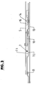
- the Ausstellschere 4 also has in a likewise known manner an additional arm or lever 10, which at one end by means of a hinge pin 11 on the stay and hinged at the other end by means of a hinge pin 12 on the faceplate 7 is and in the representation chosen for the figure 2 in a plane below the Ausstellarmes 5, but above the top 7.1 of the faceplate 7 is located.
- the turn-tilt fitting is designed as a drive rod fitting, i. at the Faceplate 7 is a drive rod 13 axially and in Stulpschienenltellsraum for slidably guided a stroke of predetermined length.
- the drive rod 13 is located on the side facing away from the extension arm 5 and the additional arm 10 bottom 7.2 the Stulpschine and is provided with a plurality of bolts formed by pins 14, the each protrude through a slot 15 on the top 7.1 of the faceplate 7.
- Each bar 14 is on the faceplate 7 facing bottom of the Ausstellarmes 5 attached to this underside a closing plate 16 assigned.
- Each closure plate 16 is in the illustrated embodiment, a molded part of a suitable material, for example of metal or zinc injection molding and is in essentially formed as a rectangular plate which at one end or at one Slab narrow side is rounded at 17. At the bottom 16.1 has the Closing plate 16 projecting, molded pin 18, which attaches to the Arm 5 allow by riveting.
- each closing plate 16 with a longitudinal direction of this Plate extending groove 19 formed open at the other narrow plate side and at which the rounding 17 having narrow side is closed.
- this groove 17 engages the associated latch 14 when locked on the faceplate 7 Ausstellarm 5 on.
- each closing plate 16 is provided with a recess 20, which is formed part-circular in the illustrated embodiment, to a curvature axis perpendicular to the plane of the underside of the closing plate 16.
- Die Closing plate 16 may at the end 17 and two or more than two recesses 20, which are offset in the transverse direction of the closing plate against each other.
- Each closing plate 16 is also mirror-symmetrical to a longitudinal axis of the rectangular closing plate enclosing and perpendicular to the plane of the Bottom-oriented center plane M1 executed.
- the gap ventilation spring 21 is a molded part of a suitable tough and permanently elastic plastic. It consists of a spring body 22 with top 23 and bottom 24 and one of this spring body 22nd molded lateral locking lug 25.
- the spring body 22 is shown in the illustrated Embodiment designed as an approximately rectangular plate, namely in the Representation of Figure 5 with a lower peripheral side 22.1, an upper Peripheral side 22.2 and two longitudinal sides 22.3 and 22.4.
- the Locking lug 25 is formed, which extends along this longitudinal side from the peripheral side 22.1 extends to the region of the peripheral side 22.2, within the planes of the top 23 and bottom 24 is located and spaced from the longitudinal side 22.4, wherein this Distance increases with increasing distance from the peripheral side 22.1.
- the spring body 22 is in a partial region 22 ', which is also the peripheral side 22.1 has formed so that there the top 23 and the bottom 24 parallel lie to each other and according to the thickness of the plate-shaped spring body spaced apart from each other.
- this peripheral side having further portion 22 is the spring body 22 slightly beveled at the top 23 and bottom 24, in such a way that the Distance between the top and bottom in this section 22 "outgoing slightly decreases towards the peripheral side 22.2. Accordingly, the locking lug 25th shaped at the top and bottom.
- an opening 26 is provided, which is for fastening the Night vent spring 21 on the faceplate 7, for example, by riveting or Screws are used. Furthermore, at the portion 22 'in the top 23 and in the Bottom 24 opposite the opening 26 offset two blind holes 27 formed, the for torsionally secure attachment of the night ventilation spring 21 on the faceplate. 7 take appropriate provided on the top 7.1 pin.
- the locking lug 25 In the region of its free end is the locking lug 25 with two bead-like notches 28 and 29 provided, which are offset in the longitudinal direction of the locking lug 25 against each other.
- the night ventilation spring 21 is mirror-symmetrical to a median plane M2 formed in the middle between the top 23 and bottom 24 extends, so that the gap ventilation spring 21st optionally for wing 1, which are opened when turning to the left, or for such can be used, which are opened when turning to the right.
- the gap ventilation spring 21 with its portion 22 'on the 7.1 top side of the faceplate 7 fixed so that they are connected to the section 22 " and with the free end of the locking lug 25 having partial length of this locking lug protrudes beyond that longitudinal side of the faceplate 7, the tilted wing 1 the Ausstellarm 5 faces and with this forms an acute angle.
- the Night vent spring 21 is further secured so that the latch 25 when closing the tilted wing 1 before reaching the final closed position, first the catch 28th and then upon further closing of the catch 29 on the recess 20 a Locking plate 16 engages.
- the gap ventilation spring 21 is further fastened so that the latching lug 25 the Additional lever 10 as well as that of the head bolt 8 and the slot 9th formed facing the joint.
- This orientation of the locking lug 25 has considerable Advantages.
- tilting position becomes the extension arm 5 with its one end in the slot 9 in FIG Direction of the gap ventilation spring 21 moves, so that thereby when locking a catch 28 and 29, the engagement of this catch is reinforced in the counter-latch 20, while the Moving the wing 1 in the closed position by moving the Ausstellarmes 5 in the slot the disengagement of the latch 28 and 29 and the counter-lock 20th is supported.
- the gap ventilation spring 21 in the respective Intermediate position the wing 1 in particular against unwanted further opening (for example, by the sash weight) reliably secures.
- the at least one locking lug 25 is in a plane parallel to the top 23 and Bottom 24 resiliently pivotable and thus attached to the face-plate 7 Gap release spring 21 in a plane perpendicular to the axis of the head bolt 8 and perpendicular to the pivot axis of the head bolt 8 and the slot 9th formed sliding swivel guide. This is also in an axial direction perpendicular to the top 7.1 of the faceplate 7 flat training of Ausstellschere 4 a sufficiently large travel for the latch 25 possible.
- FIG. 8 shows in a representation similar to FIG. 5 as further possible Embodiment, a gap ventilation spring 21a extending from the gap ventilation spring 21st only differs in that the local spring body 22a formed narrower and the locking lug 25 corresponding detent 25a is made shorter and only a catch, namely the catch 28 has.
- the inventive construction has the advantage that as a night ventilation device in essentially only a single component is required, namely the example of Plastic spring 21 or 21 a, and that as a counter-detent for this spring a Any existing strike plate can be used. Further advantages are u.a. a very simplified assembly, even with the possibility of retrofitting the Night ventilation device or the night ventilation spring. The usual function and Operation of the turn-tilt window or the corresponding fitting remains so that a simple and understandable to the user operation is possible.
- the gap ventilation spring 21 and 21 a to the faceplate 7 is attached.
- the spring with the fitting already installed and then through corresponding openings in the faceplate 7 and in the drive rod 13 therethrough to screw on the frame of the wing 1.
Abstract
Description
Die Erfindung bezieht sich auf eine Spaltlüftungsvorrichtung gemäß Oberbegriff
Patentanspruch 1.The invention relates to a night ventilation device according to the
Bekannt sind Austellscheren für kippbare, insbesondere auch für schwenk- und kippbare Flügel (auch Kipp- oder Kipp-Dreh-Flügel) von Gebäudefenstern und Gebäudetüren. Bekannt sind insbesondere auch Kipp- oder Dreh-Kipp-Beschläge, die für derartige Flügel bestimmt sind und jeweils eine Ausstellschere aufweisen, mit der die maximale Kippbewegung oder Kippöffnungsbewegung begrenzt und damit die maximale Kippstellung festgelegt wird.Are known Ausblscheren for tiltable, especially for swivel and tiltable wings (also tilt or tilt-turn wings) of building windows and Building doors. Also known are tilting or turn-tilt fittings, the are intended for such wings and each have a Ausstellschere, with the limits the maximum tilting or tilting opening movement and thus the maximum tilt position is set.
Vielfach ist es bei Kipp- oder Dreh-Kipp-Flügeln erwünscht, für den Flügel eine gesicherte Kipp- oder Zwischenstellung zwischen der maximalen Kippstellung und der Schließstellung zu ermöglichen, und zwar für einen reduzierten Lüftungsspalt, in der der Flügel festgestellt oder zumindest soweit gesichert ist, daß er erst durch Überwinden einer gewissen Kraft aus dieser Zwischenstellung bewegt werden kann.It is often desirable for tilt or turn-tilt wings, for the wing a secured tilting or intermediate position between the maximum tilt position and the To allow closed position, and for a reduced ventilation gap, in the the wing found or at least so far secured that he only by Overcoming a certain force can be moved from this intermediate position.
Eine Vorrichtung, die eine derartige gesicherte Zwischenstellung des Flügels ermöglicht, wird im Sinne der Erfindung als "Spaltlüftungsvorrichtung" bezeichnet.A device which has such a secured intermediate position of the wing allows is referred to as "gap ventilation device" in the context of the invention.
Bekannt ist ein Flügelfeststeller (DE 91 00 374.1), der im Wesentlichen aus einem an einem Blendrahmen schwenkbar vorgesehenen Hebel besteht, welcher in Hebellängsrichtung aufeinanderfolgend eine Vielzahl von Sperrzähnen aufweist. Die Sperrzähne wirken mit einem bolzenartigen, am Flügelrahmen vorgesehenen Feststellelement zusammenwirken, und zwar derart, daß in der jeweiligen, durch den Flügelfeststeller gesicherten Kippstellung das Feststellelement in einem Sperrzahn des schwenkbaren Hebels eingerastet ist. Der Flügelfeststeller ist zusätzlich zu der Ausstellschere des Dreh- und Kippfensters vorgesehen. Nachteilig ist unter anderem, daß der Flügelfeststeller sichtbar und damit optisch störend am Blendrahmen montiert ist und ein zusätzliches konstruktiv aufwendiges Funktionselement darstellt. Der Flügelfeststeller stört somit nicht nur das optische Erscheinungsbild des Fensters, sondern bedingt auch einen zusätzlichen Fertigungs- und Montageaufwand.Known is a wing lock (DE 91 00 374.1), which consists essentially of a a frame pivotally provided lever consists, which in Longitudinal lever has successively a plurality of ratchet teeth. The Ratchet teeth act with a bolt-like, provided on the sash Collapse locking element, in such a way that in the respective, by the Wing lock secured tilting the locking element in a ratchet tooth of the swung lever is engaged. The wing lock is in addition to the Ausstellschere the turn and tilt window provided. Disadvantages include that the wing lock visible and thus visually disturbing mounted on the frame is and represents an additional structurally complex functional element. Of the Wing catcher thus disturbs not only the visual appearance of the window, but also requires an additional manufacturing and assembly costs.
Bekannt ist weiterhin eine Feststellvorrichtung zur Öffnungsbegrenzung von Kipp- und Klappflügeln (DE 24 51 556 A 1). Bei dieser bekannten Vorrichtung sind die Funktionselemente für die Öffnungsbegrenzung, d. h. für die Spaltöffnung in die Ausstellschere integriert, und zwar als ein mit einer Verzahnung zusammenwirkendes Rastglied. Das Rastglied ist am Ende eines Zapfens gebildet, über den der Ausstellarm der Ausstellschere in einer Gleitführung einer Stulpschiene des Dreh-Kipp-Beschlages verschiebbar sowie auch schwenkbar geführt ist. Das Rastglied wirkt mit einer Kerbverzahnung zusammen, die an einer Treibstange des Beschlages vorgesehen ist und durch Betätigen der Treibstange aus einer nicht wirksamen Stellung in eine wirksame und damit das Rastglied verriegelnde Stellung bewegbar ist. Nachteilig bei dieser bekannten Ausbildung sind u.a. die relativ aufwendige Konstruktion und der Umstand, daß ein zuverlässiger Dauergebrauch dieser bekannten Ausstellschere nicht gewährleistet ist, da das Spiel in einer solchen Schere relativ groß ist bzw. sich bei Gebrauch durch Abnutzungserscheinungen noch vergrößert. Außerdem ist es notwendig, zur Verriegelung der jeweiligen Zwischenstellung (Spaltlüftungsstellung) den Betätigungs- oder Verschlußhebel des Beschlages entsprechend zu betätigen, was umständlich ist und eine vom Herkömmlichen abweichende gewöhnungsbedürftige Bedienung erfordert.Also known is a locking device for opening limitation of tilt and Folding wings (DE 24 51 556 A1). In this known device are the Function elements for opening limitation, d. H. for the gap opening in the Ausstellschere integrated, as a cooperating with a toothing Locking member. The locking member is formed at the end of a pin, over which the stay arm the Ausstellschere in a sliding guide a faceplate of the turn-tilt fitting slidably and also pivotally guided. The locking member acts with a Serration together, which is provided on a drive rod of the fitting and by actuating the drive rod from a non-operative position into one effective and thus the locking member locking position is movable. A disadvantage of This known training are u.a. the relatively complex construction and the The fact that a reliable continuous use of these known Ausstellschere not is guaranteed, since the game is relatively large in such a pair of scissors or at Use by signs of wear still increased. Besides, it is necessary, for locking the respective intermediate position (night ventilation position) to actuate the actuating or locking lever of the fitting accordingly is cumbersome and a deviating from the conventional getting used to Operation requires.
Bekannt ist weiterhin eine Ausstellschere (EP 0 960 999 A 1), die Zwischenstellungen bzw. Spaltlüftungsstellungen dadurch ermöglicht, daß Federmittel vorgesehen sind, die eine der Kippöffnungsbewegung entgegengesetzte Federkraft erzeugen. Diese Federmittel wirken auf das am flügelseitigen Beschlag in einer Gleitführung gleitbar und schwenkbar gehaltene Ende des Ausstellarmes ein und spannen diesen in eine dem geschlossenen Zustand des Flügels entsprechende Stellung vor. Nachteilig ist bei dieser bekannten Ausstellschere, daß beim Kippen des Flügels aus der Schließlage in die gekippte Öffnungslage die Kraft der Feder sowie auch eine nicht unerhebliche Reibungskraft überwunden werden müssen. Speziell die Reibungskraft führt zu einem erhöhten Verschleiß und zu einer nicht tolerierbaren Geräuschentwicklung. Außerdem ergibt sich insbesondere bei einem höheren Flügelgewicht keine sichere Zwischenstellung bzw. Spaltlüftungsstellung für den Flügel.Also known is a Ausstellschere (EP 0 960 999 A 1), the intermediate positions or night ventilation positions made possible by spring means are provided, the create a spring force opposite to the tilting opening movement. These Spring means are slidable on the wing-side fitting in a sliding guide and pivotally held end of the Ausstellarmes and tension this in one the closed state of the wing corresponding position. The disadvantage is at this known Ausstellschere that when tilting the wing from the closed position in the tilted opening position the force of the spring as well as a not insignificant Frictional force must be overcome. Especially the frictional force leads to a increased wear and unacceptable noise. Furthermore results in particular at a higher wing weight no safe Intermediate position or gap ventilation position for the wing.
Aufgabe der Erfindung ist es, eine vereinfachte Spaltlüftungsvorrichtung aufzuzeigen,
deren Funktionselmente verdeckt, d. h. optisch nicht sichtbar am Flügel und am
Blendrahmen oder an den Funktionselementen einer Ausstellschere vorgesehen sind.
Zur Lösung dieser Aufgabe ist eine Spaltlüftungsvorrichtung entsprechend dem
Patentanspruch 1 ausgebildet.The object of the invention is to show a simplified night ventilation device,
whose functional elements are obscured, d. H. optically not visible on the wing and on the
Frame or are provided on the functional elements of a Ausstellschere.
To solve this problem is a gap ventilation device according to the
Die Spaltlüftungsvorrichtung gemäß der Erfindung kann besonders einfach und kostengünstig realisiert werden. Hierfür ist beispielsweise an einer Ausstellschere üblicher Bauart als zusätzliches Funktionselement lediglich eine Spaltlüftungsfeder erforderlich, die dann z.B. am Beschlagteil oder an der Stulpschiene montiert wird und mit einer Gegenrast zusammenwirkt, die beispielsweise am Ausstellarm vorgesehen ist. Die Gegenrast ist dabei bevorzugt von einer an dem Ausstellarm ohnehin benötigten Schließplatte gebildet.The night ventilation device according to the invention can be particularly simple and be realized cost. This is for example on a Ausstellschere conventional design as an additional functional element only a gap ventilation spring required, which then e.g. is mounted on the fitting or on the faceplate and interacts with a counter-latch, which is provided for example on the stay. The counter-detent is preferred by a required on the stay anyway Closing plate formed.
Die Spaltlüftungsfeder beansprucht nur einen kleinen Bauraum und kann einfach montiert werden, insbesondere auch als Nachrüstteil. Weiterhin kann die Spaltlüftungsfeder als Formteil aus Kunststoff, beispielsweise als Spritzgießteil aus Kunststoff besonders einfach und preiswert gefertigt werden.The night ventilation spring takes up only a small space and can be simple be mounted, especially as retrofit. Furthermore, the Night vent spring as molding made of plastic, for example as injection molded part Plastic can be made particularly simple and inexpensive.
Eine übermäßige Reibung und damit verbunden ein übermäßiger Verschleiß sind bei der Erfindung ebenso vermieden wie eine nicht tolerierbare Geräuschentwicklung. Die übliche, dem Benutzer vertraute Bedienung eines Flügels bzw. des an diesem Flügel vorgesehenen Kippbeschlages oder Dreh-Kipp-Beschlages werden durch die erfindungsgemäße Ausbildung nicht verändert, d. h. die gewohnte Bedienung wird beibehalten. Excessive friction and associated excessive wear are included avoided the invention as well as a non-tolerable noise. The usual, the user familiar operation of a wing or on this wing provided tilting fitting or turn-tilt fitting are by the inventive design not changed, d. H. the usual operation becomes maintained.
Die Erfindung wird im Folgenden anhand der Figuren an einem Ausführungsbeispiel näher erläutert. Es zeigen:
- Fig. 1
- in vereinfachter Darstellung ein Dreh-Kipp-Fenster;
- Fig. 2 und 3
- jeweils in Teildarstellung und in Draufsicht (Figur 2) und in Seitenansicht (Figur 3) eine Ausstellschere mit integrierter Spaltlüftungsvorrichtung gemäß der Erfindung;
- Fig. 4 - 7
- in perspektivischer Darstellung (Figur 4), in Draufsicht (Figur 5), in Seitenansicht (Figur 6) sowie in einem Teilschnitt (Figur 7) eine Spaltlüftungsfeder zur Verwendung bei der Vorrichtung der Figuren 2 und 3;
- Fig. 8
- in einer Darstellung ähnlich Figur 5 eine weitere Ausführungsform der Spaltlüftungsfeder zur Verwendung bei der Vorrichtung der Figuren 2 und 3;
- Fig. 9 - 12
- eine mit der Spaltlüftungsfeder zusammenwirkende Schließplatte zur Verwendung bei der Vorrichtung der Figuren 2 und 3 in perspektivischer Darstellung (Figur 9), in Draufsicht (Figur 10), in Stirnansicht (Figur 11) sowie im Längsschnitt (Figur 12).
- Fig. 1
- in a simplified representation of a turn-tilt window;
- FIGS. 2 and 3
- each in partial view and in plan view (Figure 2) and in side view (Figure 3) a Ausstellschere with integrated gap ventilation device according to the invention;
- Fig. 4-7
- in a perspective view (Figure 4), in plan view (Figure 5), in side view (Figure 6) and in a partial section (Figure 7) a gap ventilation spring for use in the apparatus of Figures 2 and 3;
- Fig. 8
- in a representation similar to Figure 5, a further embodiment of the night ventilation spring for use in the apparatus of Figures 2 and 3;
- Fig. 9 - 12
- a cooperating with the gap ventilation spring closing plate for use in the apparatus of Figures 2 and 3 in a perspective view (Figure 9), in plan view (Figure 10), in front view (Figure 11) and in longitudinal section (Figure 12).
In den Figuren ist 1 der Flügel eines Dreh-Kipp-Fensters, der mit Hilfe eines geeigneten Beschlages (Dreh-Kipp-Beschlag) in einem Stock- oder Blendrahmen 2 um eine vertikale Achse VA schwenkbar sowie um eine horizontale Achse HA kippbar vorgesehen ist.In the figures, 1 is the wing of a turn-tilt window, with the help of a suitable Fittings (turn-tilt fitting) in a floor or frame 2 around one vertical axis VA pivotable and tiltable about a horizontal axis HA is provided.
Teil des in bekannter Weise über einen Griff 3 betätigbaren Beschlages ist u.a. eine
Kipp- oder Ausstellschere 4, die im oberen horizontalen Falzbereich des Flügels 1
sowie des Blendrahmens 2 vorgesehen ist: Die Ausstellschere 4 besteht in an sich
bekannter Weise aus einem Ausstellarm 5, der an einem Ende mittels eines Lagers 6
am Blendrahmen 3 angelenkt ist, und zwar u.a. für ein Schwenken um die Achse VA.
Das andere Ende des Ausstellarmes 4 ist etwa in der Mitte des Flügels 1 an einer im
Falz des Flügels montierten Stulpschiene 7 des Dreh- und Kippbeschlages gleitend und
schwenkbar geführt, und zwar mit Hilfe eines an diesem Ende des Ausstellarmes 5
vorgesehenen Gelenk- oder Kopfbolzens 8, der in einem eine Führung bildenden und
sich in Längsrichtung,der Stuplschiene erstreckenden Langloch 9 für ein Schwenken
sowie axiales Verschieben in Richtung der Längsachse der Stulpschiene 7 geführt ist.
Die Ausstellschere 4 weist weiterhin in ebenfalls bekannter Weise einen Zusatzarm
oder -hebel 10 auf, der mit einem Ende mittels eines Gelenkbolzens 11 am Ausstellarm
und am anderen Ende mittels eines Gelenkbolzens 12 an der Stulpschiene 7 angelenkt
ist und sich bei der für die Figur 2 gewählten Darstellung in einer Ebene Unterhalb des
Ausstellarmes 5, aber oberhalb der Oberseite 7.1 der Stulpschiene 7 befindet.Part of the actuated in a known manner via a
Der Dreh-Kipp-Beschlag ist als Treibstangenbeschlag ausgeführt, d.h. an der
Stulpschiene 7 ist eine Treibstange 13 axial und in Stulpschienenlängsrichtung für
einen Hub vorgegebener Länge verschiebbar geführt. Die Treibstange 13 befindet sich
dabei an der dem Ausstellarm 5 und dem Zusatzarm 10 abgewandten Unterseite 7.2
der Stulpschine und ist mit mehreren, von Zapfen gebildeten Riegeln 14 versehen, die
jeweils durch ein Langloch 15 über die Oberseite 7.1 der Stulpschiene 7 vorstehen.
Jedem Riegel 14 ist an der der Stulpschiene 7 zugewandten Unterseite des
Ausstellarmes 5 eine an dieser Unterseite befestigte Schließplatte 16 zugeordnet.The turn-tilt fitting is designed as a drive rod fitting, i. at the
Jede Schließplatte 16 ist bei der dargestellten Ausführungsform ein Formteil aus einem
geeigneten Material, beispielsweise aus Metall- oder Zinkspritzguß und ist im
wesentlichen als rechteckförmige Platte ausgebildet, die an einem Ende oder an einer
Plattenschmalseite bei 17 abgerundet ist. An der Unterseite 16.1 weist die
Schließplatte 16 vorstehende, angeformte Zapfen 18 auf, die ein Befestigen am
Ausstellarm 5 durch Vernieten ermöglichen.Each
An der Oberseite 16.2 ist jede Schließplatte 16 mit einer sich in Längsrichtung dieser
Platte erstreckenden Nut 19 ausgebildet, die an der anderen Plattenschmalseite offen
und an der die Abrundung 17 aufweisenden Schmalseite verschlossen ist. In diese Nut
17 greift der zugehörige Riegel 14 bei an der Stulpschiene 7 verriegeltem Ausstellarm
5 ein. Über das offene Ende ist der Riegel 14 beim Verriegeln und Entriegeln in die
Nut 19 einführbar bzw. aus dieser herausbewegbar. An der Außenfläche des
abgerundeten Endes 17 ist jede Schließplatte 16 mit einer Ausnehmung 20 versehen,
die bei der dargestellten Ausführungsform teilkreisförmig ausgebildet ist, und zwar um
eine Krümmungsachse senkrecht zur Ebene der Unterseite der Schließplatte 16. Die
Schließplatte 16 kann an dem Ende 17 auch zwei oder mehr als zwei Ausnehmungen
20 aufweisen, die in Querrichtung der Schließplatte gegeneinander versetzt sind.At the top 16.2 is each closing
Jede Schließplatte 16 ist weiterhin spiegelsymmetrisch zu einer die Längsachse der
rechteckförmigen Schließplatte einschließenden und senkrecht zur Ebene der
Unterseite orientierten Mittelebene M1 ausgeführt.Each closing
Bei geschlossenem und verriegeltem Flügel 1 liegen Ausstellarm 5, Zusatzarm 10 und
Stulpschiene 7 deckungsgleich übereinander und jeder Riegel 14 greift in seine
Schließplatte 16 ein, wodurch der Ausstellarm 5 an der Stulpschiene verriegelt ist, um
so den Flügel 1 im geschlossenen Zustand zu halten bzw. um die Achse VA
schwenken zu können. Durch entsprechendes Bewegen der Treibstange 13 werden bei
in der Schließlage befindlichem Flügel 1 die Schließplatten 16 von den Riegeln 14
freigegeben, so daß der Flügel 1 unter Schwenken des Ausstellarmes 5 relativ zur
Stulpschiene 7 sowie unter Gleiten des Kopfbolzens 8 im Langloch 9 zum Öffnen
gekippt werden kann. Die maximale Kippstellung ist dann erreicht, wenn der
Kopfbolzen 8 gegen das dem Zusatzarm 10 zugewandte Ende des Langloches 9
anliegt.With closed and locked
Vielfach ist es nun erwünscht, den Flügel 1 nicht vollständig, d.h. in seine maximale
Öffnungs- oder Kippstellung zu kippen, sondern in eine Zwischenstellung, die
zwischen der Schließlage und der maximalen Kippstellung liegt und in der ein nur
schmaler Lüftungsspalt zwischen Blendrahmen und Flügel besteht. Um dies zu
ermöglichen ist an der Oberseite 7.1 der Stulpschiene 7 eine Spaltlüftungsfeder 21
befestigt. In many cases, it is now desired not to completely cover the
Die Ausbildung dieser Feder ist in den Figuren 4 - 5 im Detail wiedergegeben. Bei der
dargestellten Ausführungsform ist die Spaltlüftungsfeder 21 ein Formteil aus einem
geeigneten zähen und dauerelastischen Kunststoff. Sie besteht aus einem Federkörper
22 mit Oberseite 23 und Unterseite 24 sowie aus einer an diesem Federkörper 22
angeformten seitlichen Rastnase 25. Der Federkörper 22 ist bei der dargestellten
Ausführungsform als in etwa rechteckförmige Platte ausgeführt, und zwar bei der
Darstellung der Figur 5 mit einer unteren Umfangsseite 22.1, einer oberen
Umfangsseite 22.2 und zwei Längsseiten 22.3 und 22.4. An der Längsseite 22.4 ist die
Rastnase 25 angeformt, die sich entlang dieser Längsseite von der Umfangsseite 22.1
bis in den Bereich der Umfangsseite 22.2 erstreckt, innerhalb der Ebenen der Oberseite
23 und Unterseite 24 liegt und von der Längsseite 22.4 beabstandet ist, wobei dieser
Abstand mit zunehmendem Abstand von der Umfangsseite 22.1 zunimmt.The design of this spring is shown in Figures 4 - 5 in detail. In the
illustrated embodiment, the
Der Federkörper 22 ist in einem Teilbereich 22', der auch die Umfangsseite 22.1
aufweist so ausgebildet, daß dort die Oberseite 23 und die Unterseite 24 parallel
zueinander liegen und entsprechend der Dicke des plattenförmigen Federkörpers
voneinander beabstandet sind. In einem zur Umfangsseite 22.2 hin anschließenden
und diese Umfangsseite aufweisenden weiteren Teilabschnitt 22" ist der Federkörper
22 an der Oberseite 23 und Unterseite 24 leicht abgeschrägt, und zwar derart, daß der
Abstand zwischen Oberseite und Unterseite in diesem Teilabschnitt 22" ausgehend
zur Umfangsseite 22.2 hin geringfügig abnimmt. Entsprechend ist auch die Rastnase 25
an der Oberseite und Unterseite geformt.The
Am Teilabschnitt 22' ist eine Öffnung 26 vorgesehen, die zum Befestigen der
Spaltlüftungsfeder 21 an der Stulpschiene 7 beispielsweise durch Nieten oder
Schrauben dient. Weiterhin sind am Teilabschnitt 22' in der Oberseite 23 und in der
Unterseite 24 gegenüber der Öffnung 26 versetzt zwei Sacklöcher 27 eingeformt, die
zur verdrehungssicheren Befestigung der Spaltlüftungsfeder 21 an der Stulpschiene 7
entsprechende an der Oberseite 7.1 vorgesehene Zapfen aufnehmen. At the portion 22 ', an
Im Bereich ihres freien Endes ist die Rastnase 25 mit zwei wulstartigen Rasten 28 und
29 versehen, die in Längsrichtung der Rastnase 25 gegeneinander versetzt sind.In the region of its free end is the locking
Wie die Figuren 4 - 7 weiterhin zeigen, ist die Spaltlüftungsfeder 21
spiegelsymmetrisch zu einer Mittelebene M2 ausgebildet, die in der Mitte zwischen
der Oberseite 23 und Unterseite 24 verläuft, so daß die Spaltlüftungsfeder 21
wahlweise für Flügel 1, die beim Drehen nach links geöffnet werden, oder für solche
eingesetzt werden kann, die beim Drehen nach rechts geöffnet werden.As FIGS. 4 to 7 furthermore show, the
Wie die Figur 2 zeigt, ist die Spaltlüftungsfeder 21 mit ihrem Teilabschnitt 22' an der
Oberseite 7.1 der Stulpschiene 7 derart befestigt, daß sie mit dem Teilabschnitt 22"
sowie mit der das freie Ende der Rastnase 25 aufweisenden Teillänge dieser Rastnase
über diejenige Längsseite der Stulpschiene 7 wegsteht, die bei gekipptem Flügel 1 dem
Ausstellarm 5 zugewandt ist und mit diesem einen spitzen Winkel einschließt. Die
Spaltlüftungsfeder 21 ist weiterhin so befestigt, daß die Rastnase 25 beim Schließen
des gekippten Flügels 1 vor Erreichen der endgültigen Schließlage zunächst die Rast 28
und dann beim weiteren Schließen der Rast 29 an der Ausnehmung 20 einer
Schließplatte 16 einrastet. Hierdurch ergeben sich zwei Kipp- oder Zwischenstellungen
für den Flügel 1, in denen zwischen dem Flügel 1 und dem Blendrahmen 2 nur ein
reduzierter Lüftungsspalt verbleibt, und zwar beim Einrasten der Rast 28 in die
Gegenrast oder Ausnehmung 20 ein Lüftungsspalt größerer Breite als beim Einrasten
der Rast 29 in die Ausnehmung 20.As the figure 2 shows, the
Die Spaltlüftungsfeder 21 ist weiterhin so befestigt, daß die Rastnase 25 dem
Zusatzhebel 10 sowie auch dem von dem Kopfbolzen 8 und dem Langloch 9
gebildeten Gelenk zugewandt ist. Diese Orientierung der Rastnase 25 hat erhebliche
Vorteile. Beim Kippen des Flügel 1 aus seiner Schließlage in die Öffnungslage bzw.
Kippstellung wird nämlich der Ausstellarm 5 mit seinem einen Ende im Langloch 9 in
Richtung der Spaltlüftungsfeder 21 bewegt, so daß hierdurch beim Einrasten einer Rast
28 bzw. 29 der Eingriff dieser Rast in die Gegenrast 20 verstärkt wird, während beim
Bewegen des Flügels 1 in die Schließstellung durch das Verschieben des Ausstellarmes
5 im Langloch das Außereingriffkommen der Rast 28 bzw. 29 und der Gegenrast 20
unterstützt wird. Dies bedeutet, daß die Spaltlüftungsfeder 21 in der jeweiligen
Zwischenstellung den Flügel 1 insbesondere gegen ein unerwünschtes weiteres Öffnen
(beispielsweise durch das Flügelgewicht) zuverlässig sichert.The
Sowohl in der endgültigen Schließlage, als auch in der maximal gekippten Stellung ist
die Spaltlüftungsfeder 21 außer Eingriff mit der an der zugehörigen Schließplatte 16
gebildeten Gegenrast 20.Both in the final closed position, as well as in the maximum tilted position
the
In der Schließstellung des Flügels 1 sind die Spaltlüftungsfeder 21 bzw. deren
Federkörper 22 zwischen dem Ausstellarm 5 und der Stulpschiene 7 angeordnet.In the closed position of the
Die wenigstens eine Rastnase 25 ist in einer Ebene parallel zu der Oberseite 23 bzw.
Unterseite 24 federnd schwenkbar und damit bei an der Stulpschiene 7 befestigten
Spaltlüftungsfeder 21 in einer Ebene senkrecht zu der Achse des Kopfbolzens 8 bzw.
senkrecht zur Schwenkachse der von diesem Kopfbolzen 8 und dem Langloch 9
gebildeten Gleit-Schwenk-Führung. Hierdurch ist auch bei in einer Achsrichtung
senkrecht zur Oberseite 7.1 der Stulpschiene 7 flachen Ausbildung der Ausstellschere
4 ein ausreichend großer Federweg für die Rastnase 25 möglich.The at least one locking
Die Figur 8 zeigt in einer Darstellung ähnlich Figur 5 als weitere mögliche
Ausführungsform eine Spaltlüftungsfeder 21a, die sich von der Spaltlüftungsfeder 21
lediglich dadurch unterscheidet, daß der dortige Federkörper 22a schmäler ausgebildet
und die der Rastnase 25 entsprechende Rastnase 25a kürzer ausgeführt ist sowie nur
eine Rast, nämlich die Rast 28 aufweist.FIG. 8 shows in a representation similar to FIG. 5 as further possible
Embodiment, a
Die erfindungsgemäße Ausbildung hat den Vorteil, daß als Spaltlüftungsvorrichtung im
wesentlichen nur ein einziges Bauteil erforderlich ist, nämlich die beispielsweise aus
Kunststoff hergestellte Feder 21 bzw. 21 a, und daß als Gegenrast für diese Feder eine
ohnehin vorhandene Schließplatte verwendet werden kann. Weitere Vorteile sind u.a.
eine sehr vereinfachte Montage, auch mit der Möglichkeit einer Nachrüstung der
Spaltlüftungsvorrichtung oder der Spaltlüftungsfeder. Die übliche Funktion und
Bedienung des Dreh-Kipp-Fensters bzw. des entsprechenden Beschlages bleibt
erhalten, so daß eine einfache und für den Benutzer auch verständliche Bedienung
möglich ist.The inventive construction has the advantage that as a night ventilation device in
essentially only a single component is required, namely the example of
Die Erfindung wurde voranstehend an Ausführungsbeispielen beschrieben. Es versteht sich, daß zahlreiche Änderungen sowie Abwandlungen möglich sind, ohne daß dadurch der der Erfindung zugrundeliegende Erfindungsgedanke verlassen wird.The invention has been described above by means of exemplary embodiments. It understands that many changes and modifications are possible without As a result, the invention underlying the invention is abandoned.
So wurde vorstehend davon ausgegangen, daß die Spaltlüftungsfeder 21 bzw. 21a an
der Stulpschiene 7 befestigt ist. Grundsätzlich besteht aber auch die Möglichkeit, diese
Feder beispielsweise bei bereits montiertem Beschlag nachzurüsten und dann durch
entsprechende Öffnungen in der Stulpschiene 7 sowie in der Treibstange 13 hindurch
am Rahmen des Flügels 1 anzuschrauben. So it was assumed above that the
- 11
- Dreh-Kipp-FlügelTilt-wing
- 22
- Blendrahmenframe
- 33
- GriffHandle
- 44
- Ausstellscherescissor
- 55
- Ausstellarmout arm
- 66
- Lagercamp
- 77
- Stulpschienefaceplate
- 7.17.1
- Oberseite der StulpschieneTop of the faceplate rail
- 7.27.2
- Unterseite der StulpschieneBottom of the faceplate
- 88th
- Kopfbolzenstuds
- 99
- LanglochLong hole
- 1010
- Zusatzarmadditional arm
- 11, 1211, 12
-
Gelenk für Zusatzarm 10Joint for
additional arm 10 - 1313
- Treibstangedriving rod
- 1414
- Riegel oder BolzenLatch or bolt
- 1515
-
Langloch für Riegel 14 in der StulpschieneSlot for
bolt 14 in the faceplate - 1616
- Schließplatteclosing plate
- 16.116.1
- SchließplattenunterseiteClosing plate underside
- 16.216.2
- SchließplattenoberseiteClosing plate upper side
- 1717
- abgerundetes Ende der Schließplatterounded end of the closing plate
- 1818
- Befestigungszapfenfastening pins
- 1919
- Nutgroove
- 2020
- Ausnehmung oder GegenrastRecess or counter-latching
- 21, 21a21, 21a
- SpaltlüftungsfederNight vent spring
- 22, 22a22, 22a
- Federkörperspring body
- 22', 22"22 ', 22 "
- Teilbereich des Federkörpers 22Part of the spring body 22nd
- 22.1, 22.2, 22.3, 22.422.1, 22.2, 22.3, 22.4
-
Umfangsseiten des Federkörpers 22Circumferential sides of the
spring body 22 - 2323
- Oberseite des Federkörpers 22Top of the spring body 22nd
- 2424
-
Unterseite des Federkörpers 22 Bottom of the
spring body 22 - 25, 25a25, 25a
- Rastnaselocking lug
- 2626
- Befestigungsöffnungfastening opening
- 2727
- Sackbohrungblind hole
- 28, 2928, 29
- Rastrest
- M1, M2M1, M2
- Mittelebenemidplane
Claims (16)
daß am Schwenkarm (5) oder am Beschlagteil (7) wenigstens eine Gegenrast (20) vorgesehen ist, in die die wenigstens eine Rast (28, 29) der Rastnase (25, 25a) in der Kippstellung federnd einrastet.A gap opening device for a wing (1) of a building window or a building door, which is at least tiltable in a glazing or floor frame (2), with a swivel arm (5) at one end with a first bearing (6) on the window frame (2) at the other End with a second bearing (7, 8, 9) can be fastened to the wing, and with a between the pivot arm (5) and a fitting part (7) of one of the bearing acting locking member (21) which by latching the wing (1) ascertains in at least one tilted position, characterized in that the detent member comprises at least one gap release spring (21) provided on the fitting part (7) and / or on the pivot arm (5) with a resilient detent nose (25, 25a) having at least one detent (28, 29) is and
that on the pivot arm (5) or on the fitting part (7) at least one counter-latching (20) is provided in which the at least one detent (28, 29) of the latching lug (25, 25a) resiliently engages in the tilted position.
daß die Kippstellung, in der die Spaltlüftungsfeder (21) an der wenigstens einen Gegenrast (20) einrastet, eine Zwischenstellung zwischen einer maximalen Kippstellung des Flügels (1) und einer geschlossenen Stellung dieses Flügels (1) ist.A gap-opening device according to claim 1, characterized in that the swivel arm is an extension arm (5) of a tilting scissor (4) limiting the tilting movement of the wing (1), and
in that the tilting position in which the gap ventilation spring (21) engages on the at least one mating catch (20) is an intermediate position between a maximum tilted position of the sash (1) and a closed position of this sash (1).
und/oder
daß die Spaltlüftungsfeder (21) spiegelsymmetrisch zu einer zwischen einer Oberseite (23) und einer Unterseite (24) der Feder verlaufenden Mittelebene (M 2) ausgebildet ist.Night ventilation device according to one of the preceding claims, characterized in that the night ventilation spring (21) including the spring body (22) and latching lug (25, 25a) is substantially plate-shaped;
and or
in that the gap ventilation spring (21) is mirror-symmetrical to a median plane (M 2) extending between an upper side (23) and a lower side (24) of the spring.
und/oder
daß der Federkörper (22) in dem Teilabschnitt eine sich zu einem freien Rand (22.2) dieses Teilabschnittes hin reduzierende Dicke aufweist.A gap ventilation device according to one of the preceding claims, characterized in that the latching nose (25) has a thickness which reduces towards the free end of the latching nose in a partial area,
and or
in that the spring body (22) in the section has a thickness which reduces towards a free edge (22.2) of this section.
und/oder
daß wenigstens zwei Gegenrasten vorgesehen sind, vorzugsweise an der Schließplatte (16).Night ventilation device according to one of the preceding claims, characterized in that the fitting part (7) is a faceplate rail (7) of a tilting or turn-tilt fitting designed as an espagnolette fitting,
and or
that at least two counter-detents are provided, preferably on the closing plate (16).
Applications Claiming Priority (2)
| Application Number | Priority Date | Filing Date | Title |
|---|---|---|---|
| DE20310889U | 2003-07-15 | ||
| DE20310889U DE20310889U1 (en) | 2003-07-15 | 2003-07-15 | Gap ventilation device |
Publications (2)
| Publication Number | Publication Date |
|---|---|
| EP1498563A1 true EP1498563A1 (en) | 2005-01-19 |
| EP1498563B1 EP1498563B1 (en) | 2006-06-14 |
Family
ID=29285908
Family Applications (1)
| Application Number | Title | Priority Date | Filing Date |
|---|---|---|---|
| EP04007489A Expired - Lifetime EP1498563B1 (en) | 2003-07-15 | 2004-03-27 | Device for providing a ventilation gap |
Country Status (3)
| Country | Link |
|---|---|
| EP (1) | EP1498563B1 (en) |
| AT (1) | ATE330097T1 (en) |
| DE (2) | DE20310889U1 (en) |
Cited By (1)
| Publication number | Priority date | Publication date | Assignee | Title |
|---|---|---|---|---|
| BE1016962A3 (en) * | 2006-01-23 | 2007-11-06 | Van Parys Remi E | Concealed hinge for e.g. window, comprises first part fixed to frame and second part slidably secured to wing |
Families Citing this family (2)
| Publication number | Priority date | Publication date | Assignee | Title |
|---|---|---|---|---|
| DE102005018429A1 (en) * | 2005-04-21 | 2006-10-26 | Carl Fuhr Gmbh & Co. Kg | Tilt & turn window fitting with gap ventilation position |
| JP6178248B2 (en) * | 2014-01-15 | 2017-08-09 | Ykk Ap株式会社 | Joinery |
Citations (5)
| Publication number | Priority date | Publication date | Assignee | Title |
|---|---|---|---|---|
| EP0256213A1 (en) * | 1986-08-09 | 1988-02-24 | Siegenia-Frank Kg | Latching device in a tilt position, for pivoting and tilting wrings, windows, doors |
| EP0556453A1 (en) * | 1992-02-11 | 1993-08-25 | AUGUST BILSTEIN GMBH & CO. KG | Tilt-lock device |
| EP0957224A1 (en) * | 1998-05-12 | 1999-11-17 | Siegenia-Frank Kg | Tilt-lock device. |
| EP0960999A1 (en) * | 1998-05-26 | 1999-12-01 | Rudolf Boog | Tilting window |
| DE10013697A1 (en) * | 2000-03-21 | 2001-09-27 | Siegenia Frank Kg | Door window check uses latching system composed of odd-sized teeth on support rod end co-operating with latches during casement movement. |
-
2003
- 2003-07-15 DE DE20310889U patent/DE20310889U1/en not_active Expired - Lifetime
-
2004
- 2004-03-27 DE DE502004000751T patent/DE502004000751D1/en not_active Expired - Fee Related
- 2004-03-27 EP EP04007489A patent/EP1498563B1/en not_active Expired - Lifetime
- 2004-03-27 AT AT04007489T patent/ATE330097T1/en not_active IP Right Cessation
Patent Citations (5)
| Publication number | Priority date | Publication date | Assignee | Title |
|---|---|---|---|---|
| EP0256213A1 (en) * | 1986-08-09 | 1988-02-24 | Siegenia-Frank Kg | Latching device in a tilt position, for pivoting and tilting wrings, windows, doors |
| EP0556453A1 (en) * | 1992-02-11 | 1993-08-25 | AUGUST BILSTEIN GMBH & CO. KG | Tilt-lock device |
| EP0957224A1 (en) * | 1998-05-12 | 1999-11-17 | Siegenia-Frank Kg | Tilt-lock device. |
| EP0960999A1 (en) * | 1998-05-26 | 1999-12-01 | Rudolf Boog | Tilting window |
| DE10013697A1 (en) * | 2000-03-21 | 2001-09-27 | Siegenia Frank Kg | Door window check uses latching system composed of odd-sized teeth on support rod end co-operating with latches during casement movement. |
Cited By (1)
| Publication number | Priority date | Publication date | Assignee | Title |
|---|---|---|---|---|
| BE1016962A3 (en) * | 2006-01-23 | 2007-11-06 | Van Parys Remi E | Concealed hinge for e.g. window, comprises first part fixed to frame and second part slidably secured to wing |
Also Published As
| Publication number | Publication date |
|---|---|
| DE502004000751D1 (en) | 2006-07-27 |
| ATE330097T1 (en) | 2006-07-15 |
| DE20310889U1 (en) | 2003-10-23 |
| EP1498563B1 (en) | 2006-06-14 |
Similar Documents
| Publication | Publication Date | Title |
|---|---|---|
| EP3363976B1 (en) | Opening by rotation limiting arrangement for a window or a door for limiting the rotation of a leaf of a window or a door | |
| EP0119433B2 (en) | Fitting for a wing of a window, door or the like, which is at least tiltable and movable from one plane to a second parallel plane | |
| EP3102759B1 (en) | Fitting for an at least liftable and slidable window or door leaf | |
| EP1568833A2 (en) | Striker plate for a window or a door | |
| EP0128371B1 (en) | Check for a tilting door or window with a pivoting and sliding bar | |
| EP2251508B1 (en) | Striker plate for windows or doors | |
| DE3022163A1 (en) | Turn and tilt window fitting providing ventilation gap - has passage for positioning lug on retainer attached to push rod | |
| EP1614844A2 (en) | Pivot device | |
| EP0600102B1 (en) | Fitting for tiltable and into a parallel plane movable and in the closed ant the tilting or parallel position lockable wings | |
| EP2772604B1 (en) | Opening restrictor | |
| DE202013008784U1 (en) | Fitting an at least liftable, but preferably also movable wing of windows or doors | |
| DE2458800C2 (en) | Snap device | |
| DE19521601C1 (en) | Window, door or the like | |
| EP1498563B1 (en) | Device for providing a ventilation gap | |
| EP0572988B1 (en) | Striking plate | |
| EP2871312B1 (en) | Ventilation gap assembly for a sliding door or window and sliding door or window | |
| DE10013697A1 (en) | Door window check uses latching system composed of odd-sized teeth on support rod end co-operating with latches during casement movement. | |
| EP0262347B1 (en) | Device for holding a partially pivoting door or window in an open position | |
| EP2107194A1 (en) | Device for limiting the opening of a window or door | |
| EP0275895B1 (en) | Fitting for an at least tiltable wing | |
| EP0380059A2 (en) | Corner bolt for doors or windows | |
| EP2806090A2 (en) | A device for locking or unlocking a sliding leaf | |
| EP1231345B1 (en) | Controlled locking device and corner guide | |
| DE3342661A1 (en) | Espagnolette fitting | |
| DE60201616T2 (en) | Lock for door, window, etc. with rod-like fitting |
Legal Events
| Date | Code | Title | Description |
|---|---|---|---|
| PUAI | Public reference made under article 153(3) epc to a published international application that has entered the european phase |
Free format text: ORIGINAL CODE: 0009012 |
|
| AK | Designated contracting states |
Kind code of ref document: A1 Designated state(s): AT BE BG CH CY CZ DE DK EE ES FI FR GB GR HU IE IT LI LU MC NL PL PT RO SE SI SK TR |
|
| AX | Request for extension of the european patent |
Extension state: AL LT LV MK |
|
| 17P | Request for examination filed |
Effective date: 20050218 |
|
| AKX | Designation fees paid |
Designated state(s): AT BE BG CH CY CZ DE DK EE ES FI FR GB GR HU IE IT LI LU MC NL PL PT RO SE SI SK TR |
|
| GRAP | Despatch of communication of intention to grant a patent |
Free format text: ORIGINAL CODE: EPIDOSNIGR1 |
|
| GRAS | Grant fee paid |
Free format text: ORIGINAL CODE: EPIDOSNIGR3 |
|
| RAP1 | Party data changed (applicant data changed or rights of an application transferred) |
Owner name: GRETSCH-UNITAS GMBH BAUBESCHLAEGE |
|
| GRAA | (expected) grant |
Free format text: ORIGINAL CODE: 0009210 |
|
| AK | Designated contracting states |
Kind code of ref document: B1 Designated state(s): AT BE BG CH CY CZ DE DK EE ES FI FR GB GR HU IE IT LI LU MC NL PL PT RO SE SI SK TR |
|
| PG25 | Lapsed in a contracting state [announced via postgrant information from national office to epo] |
Ref country code: IT Free format text: LAPSE BECAUSE OF FAILURE TO SUBMIT A TRANSLATION OF THE DESCRIPTION OR TO PAY THE FEE WITHIN THE PRESCRIBED TIME-LIMIT;WARNING: LAPSES OF ITALIAN PATENTS WITH EFFECTIVE DATE BEFORE 2007 MAY HAVE OCCURRED AT ANY TIME BEFORE 2007. THE CORRECT EFFECTIVE DATE MAY BE DIFFERENT FROM THE ONE RECORDED. Effective date: 20060614 Ref country code: GB Free format text: LAPSE BECAUSE OF FAILURE TO SUBMIT A TRANSLATION OF THE DESCRIPTION OR TO PAY THE FEE WITHIN THE PRESCRIBED TIME-LIMIT Effective date: 20060614 Ref country code: CZ Free format text: LAPSE BECAUSE OF FAILURE TO SUBMIT A TRANSLATION OF THE DESCRIPTION OR TO PAY THE FEE WITHIN THE PRESCRIBED TIME-LIMIT Effective date: 20060614 Ref country code: IE Free format text: LAPSE BECAUSE OF FAILURE TO SUBMIT A TRANSLATION OF THE DESCRIPTION OR TO PAY THE FEE WITHIN THE PRESCRIBED TIME-LIMIT Effective date: 20060614 Ref country code: NL Free format text: LAPSE BECAUSE OF FAILURE TO SUBMIT A TRANSLATION OF THE DESCRIPTION OR TO PAY THE FEE WITHIN THE PRESCRIBED TIME-LIMIT Effective date: 20060614 Ref country code: FI Free format text: LAPSE BECAUSE OF FAILURE TO SUBMIT A TRANSLATION OF THE DESCRIPTION OR TO PAY THE FEE WITHIN THE PRESCRIBED TIME-LIMIT Effective date: 20060614 Ref country code: PL Free format text: LAPSE BECAUSE OF FAILURE TO SUBMIT A TRANSLATION OF THE DESCRIPTION OR TO PAY THE FEE WITHIN THE PRESCRIBED TIME-LIMIT Effective date: 20060614 Ref country code: RO Free format text: LAPSE BECAUSE OF FAILURE TO SUBMIT A TRANSLATION OF THE DESCRIPTION OR TO PAY THE FEE WITHIN THE PRESCRIBED TIME-LIMIT Effective date: 20060614 Ref country code: SK Free format text: LAPSE BECAUSE OF FAILURE TO SUBMIT A TRANSLATION OF THE DESCRIPTION OR TO PAY THE FEE WITHIN THE PRESCRIBED TIME-LIMIT Effective date: 20060614 Ref country code: SI Free format text: LAPSE BECAUSE OF FAILURE TO SUBMIT A TRANSLATION OF THE DESCRIPTION OR TO PAY THE FEE WITHIN THE PRESCRIBED TIME-LIMIT Effective date: 20060614 |
|
| REG | Reference to a national code |
Ref country code: GB Ref legal event code: FG4D Free format text: NOT ENGLISH |
|
| REG | Reference to a national code |
Ref country code: CH Ref legal event code: EP |
|
| REG | Reference to a national code |
Ref country code: IE Ref legal event code: FG4D Free format text: LANGUAGE OF EP DOCUMENT: GERMAN |
|
| REF | Corresponds to: |
Ref document number: 502004000751 Country of ref document: DE Date of ref document: 20060727 Kind code of ref document: P |
|
| PG25 | Lapsed in a contracting state [announced via postgrant information from national office to epo] |
Ref country code: DK Free format text: LAPSE BECAUSE OF FAILURE TO SUBMIT A TRANSLATION OF THE DESCRIPTION OR TO PAY THE FEE WITHIN THE PRESCRIBED TIME-LIMIT Effective date: 20060914 Ref country code: SE Free format text: LAPSE BECAUSE OF FAILURE TO SUBMIT A TRANSLATION OF THE DESCRIPTION OR TO PAY THE FEE WITHIN THE PRESCRIBED TIME-LIMIT Effective date: 20060914 |
|
| PG25 | Lapsed in a contracting state [announced via postgrant information from national office to epo] |
Ref country code: ES Free format text: LAPSE BECAUSE OF FAILURE TO SUBMIT A TRANSLATION OF THE DESCRIPTION OR TO PAY THE FEE WITHIN THE PRESCRIBED TIME-LIMIT Effective date: 20060925 |
|
| PG25 | Lapsed in a contracting state [announced via postgrant information from national office to epo] |
Ref country code: PT Free format text: LAPSE BECAUSE OF FAILURE TO SUBMIT A TRANSLATION OF THE DESCRIPTION OR TO PAY THE FEE WITHIN THE PRESCRIBED TIME-LIMIT Effective date: 20061114 |
|
| NLV1 | Nl: lapsed or annulled due to failure to fulfill the requirements of art. 29p and 29m of the patents act | ||
| GBV | Gb: ep patent (uk) treated as always having been void in accordance with gb section 77(7)/1977 [no translation filed] |
Effective date: 20060614 |
|
| REG | Reference to a national code |
Ref country code: IE Ref legal event code: FD4D |
|
| PLBE | No opposition filed within time limit |
Free format text: ORIGINAL CODE: 0009261 |
|
| STAA | Information on the status of an ep patent application or granted ep patent |
Free format text: STATUS: NO OPPOSITION FILED WITHIN TIME LIMIT |
|
| EN | Fr: translation not filed | ||
| 26N | No opposition filed |
Effective date: 20070315 |
|
| BERE | Be: lapsed |
Owner name: GRETSCH-UNITAS G.M.B.H. BAUBESCHLAGE Effective date: 20070331 |
|
| PG25 | Lapsed in a contracting state [announced via postgrant information from national office to epo] |
Ref country code: BE Free format text: LAPSE BECAUSE OF NON-PAYMENT OF DUE FEES Effective date: 20070331 |
|
| PG25 | Lapsed in a contracting state [announced via postgrant information from national office to epo] |
Ref country code: MC Free format text: LAPSE BECAUSE OF NON-PAYMENT OF DUE FEES Effective date: 20070331 |
|
| PG25 | Lapsed in a contracting state [announced via postgrant information from national office to epo] |
Ref country code: FR Free format text: LAPSE BECAUSE OF FAILURE TO SUBMIT A TRANSLATION OF THE DESCRIPTION OR TO PAY THE FEE WITHIN THE PRESCRIBED TIME-LIMIT Effective date: 20070309 Ref country code: GR Free format text: LAPSE BECAUSE OF FAILURE TO SUBMIT A TRANSLATION OF THE DESCRIPTION OR TO PAY THE FEE WITHIN THE PRESCRIBED TIME-LIMIT Effective date: 20060915 |
|
| PG25 | Lapsed in a contracting state [announced via postgrant information from national office to epo] |
Ref country code: BG Free format text: LAPSE BECAUSE OF FAILURE TO SUBMIT A TRANSLATION OF THE DESCRIPTION OR TO PAY THE FEE WITHIN THE PRESCRIBED TIME-LIMIT Effective date: 20060914 Ref country code: AT Free format text: LAPSE BECAUSE OF NON-PAYMENT OF DUE FEES Effective date: 20070327 |
|
| PG25 | Lapsed in a contracting state [announced via postgrant information from national office to epo] |
Ref country code: EE Free format text: LAPSE BECAUSE OF FAILURE TO SUBMIT A TRANSLATION OF THE DESCRIPTION OR TO PAY THE FEE WITHIN THE PRESCRIBED TIME-LIMIT Effective date: 20060614 |
|
| REG | Reference to a national code |
Ref country code: CH Ref legal event code: PL |
|
| PG25 | Lapsed in a contracting state [announced via postgrant information from national office to epo] |
Ref country code: FR Free format text: LAPSE BECAUSE OF FAILURE TO SUBMIT A TRANSLATION OF THE DESCRIPTION OR TO PAY THE FEE WITHIN THE PRESCRIBED TIME-LIMIT Effective date: 20060614 |
|
| PG25 | Lapsed in a contracting state [announced via postgrant information from national office to epo] |
Ref country code: CH Free format text: LAPSE BECAUSE OF NON-PAYMENT OF DUE FEES Effective date: 20080331 Ref country code: LI Free format text: LAPSE BECAUSE OF NON-PAYMENT OF DUE FEES Effective date: 20080331 |
|
| PG25 | Lapsed in a contracting state [announced via postgrant information from national office to epo] |
Ref country code: CY Free format text: LAPSE BECAUSE OF FAILURE TO SUBMIT A TRANSLATION OF THE DESCRIPTION OR TO PAY THE FEE WITHIN THE PRESCRIBED TIME-LIMIT Effective date: 20060614 Ref country code: LU Free format text: LAPSE BECAUSE OF NON-PAYMENT OF DUE FEES Effective date: 20070327 |
|
| PGFP | Annual fee paid to national office [announced via postgrant information from national office to epo] |
Ref country code: DE Payment date: 20090320 Year of fee payment: 6 |
|
| PG25 | Lapsed in a contracting state [announced via postgrant information from national office to epo] |
Ref country code: TR Free format text: LAPSE BECAUSE OF FAILURE TO SUBMIT A TRANSLATION OF THE DESCRIPTION OR TO PAY THE FEE WITHIN THE PRESCRIBED TIME-LIMIT Effective date: 20060614 Ref country code: HU Free format text: LAPSE BECAUSE OF FAILURE TO SUBMIT A TRANSLATION OF THE DESCRIPTION OR TO PAY THE FEE WITHIN THE PRESCRIBED TIME-LIMIT Effective date: 20061215 |
|
| PG25 | Lapsed in a contracting state [announced via postgrant information from national office to epo] |
Ref country code: DE Free format text: LAPSE BECAUSE OF NON-PAYMENT OF DUE FEES Effective date: 20101001 |