EP1497883B1 - Element de base de pile a combustible limitant la traversee de l'electrolyte par le methanol - Google Patents
Element de base de pile a combustible limitant la traversee de l'electrolyte par le methanol Download PDFInfo
- Publication number
- EP1497883B1 EP1497883B1 EP03747147A EP03747147A EP1497883B1 EP 1497883 B1 EP1497883 B1 EP 1497883B1 EP 03747147 A EP03747147 A EP 03747147A EP 03747147 A EP03747147 A EP 03747147A EP 1497883 B1 EP1497883 B1 EP 1497883B1
- Authority
- EP
- European Patent Office
- Prior art keywords
- electrolyte
- anode
- fuel cell
- fuel
- element according
- Prior art date
- Legal status (The legal status is an assumption and is not a legal conclusion. Google has not performed a legal analysis and makes no representation as to the accuracy of the status listed.)
- Expired - Lifetime
Links
Images
Classifications
-
- H—ELECTRICITY
- H01—ELECTRIC ELEMENTS
- H01M—PROCESSES OR MEANS, e.g. BATTERIES, FOR THE DIRECT CONVERSION OF CHEMICAL ENERGY INTO ELECTRICAL ENERGY
- H01M4/00—Electrodes
- H01M4/86—Inert electrodes with catalytic activity, e.g. for fuel cells
- H01M4/8605—Porous electrodes
- H01M4/8626—Porous electrodes characterised by the form
-
- H—ELECTRICITY
- H01—ELECTRIC ELEMENTS
- H01M—PROCESSES OR MEANS, e.g. BATTERIES, FOR THE DIRECT CONVERSION OF CHEMICAL ENERGY INTO ELECTRICAL ENERGY
- H01M8/00—Fuel cells; Manufacture thereof
- H01M8/10—Fuel cells with solid electrolytes
- H01M8/1009—Fuel cells with solid electrolytes with one of the reactants being liquid, solid or liquid-charged
-
- H—ELECTRICITY
- H01—ELECTRIC ELEMENTS
- H01M—PROCESSES OR MEANS, e.g. BATTERIES, FOR THE DIRECT CONVERSION OF CHEMICAL ENERGY INTO ELECTRICAL ENERGY
- H01M8/00—Fuel cells; Manufacture thereof
- H01M8/10—Fuel cells with solid electrolytes
- H01M8/1097—Fuel cells applied on a support, e.g. miniature fuel cells deposited on silica supports
-
- H—ELECTRICITY
- H01—ELECTRIC ELEMENTS
- H01M—PROCESSES OR MEANS, e.g. BATTERIES, FOR THE DIRECT CONVERSION OF CHEMICAL ENERGY INTO ELECTRICAL ENERGY
- H01M4/00—Electrodes
- H01M4/86—Inert electrodes with catalytic activity, e.g. for fuel cells
- H01M2004/8678—Inert electrodes with catalytic activity, e.g. for fuel cells characterised by the polarity
- H01M2004/8684—Negative electrodes
-
- H—ELECTRICITY
- H01—ELECTRIC ELEMENTS
- H01M—PROCESSES OR MEANS, e.g. BATTERIES, FOR THE DIRECT CONVERSION OF CHEMICAL ENERGY INTO ELECTRICAL ENERGY
- H01M2300/00—Electrolytes
- H01M2300/0017—Non-aqueous electrolytes
- H01M2300/0065—Solid electrolytes
- H01M2300/0082—Organic polymers
-
- H—ELECTRICITY
- H01—ELECTRIC ELEMENTS
- H01M—PROCESSES OR MEANS, e.g. BATTERIES, FOR THE DIRECT CONVERSION OF CHEMICAL ENERGY INTO ELECTRICAL ENERGY
- H01M8/00—Fuel cells; Manufacture thereof
- H01M8/10—Fuel cells with solid electrolytes
- H01M8/1004—Fuel cells with solid electrolytes characterised by membrane-electrode assemblies [MEA]
-
- Y—GENERAL TAGGING OF NEW TECHNOLOGICAL DEVELOPMENTS; GENERAL TAGGING OF CROSS-SECTIONAL TECHNOLOGIES SPANNING OVER SEVERAL SECTIONS OF THE IPC; TECHNICAL SUBJECTS COVERED BY FORMER USPC CROSS-REFERENCE ART COLLECTIONS [XRACs] AND DIGESTS
- Y02—TECHNOLOGIES OR APPLICATIONS FOR MITIGATION OR ADAPTATION AGAINST CLIMATE CHANGE
- Y02E—REDUCTION OF GREENHOUSE GAS [GHG] EMISSIONS, RELATED TO ENERGY GENERATION, TRANSMISSION OR DISTRIBUTION
- Y02E60/00—Enabling technologies; Technologies with a potential or indirect contribution to GHG emissions mitigation
- Y02E60/30—Hydrogen technology
- Y02E60/50—Fuel cells
Definitions
- the invention relates to the field of Proton Exchange Membrane (PEM) type fuel cells, and in particular those of the "DMFC” type (Direct Methanol Fuell Cell), using methanol or another alcohol such as combustible.
- PEM Proton Exchange Membrane
- DMFC Direct Methanol Fuell Cell
- Fuel cells generally use hydrogen as fuel and oxidizer as oxygen. However, in the case of fuel cells for powering portable equipment, the volume occupied by the fuel must be reduced to a minimum. In view of the fact that the energy density of liquid fuels is generally greater than that of hydrogen, they are therefore chosen as fuel.
- the fuel is intended to be catalytically oxidized at the anode to give successive protons, electrons, and oxidation products that can lead to carbon dioxide. carbon.
- the electrolyte generally consists of a proton conducting membrane of the type Nafion ® leads the protons to the cathode to react with oxygen and form water.
- the major difficulty of this type of fuel cell lies in the permeation of the fuel, through the electrolyte membrane to react with the cathode directly with oxygen. This reaction has two major consequences which are the creation of a mixed voltage at the cathode, lowering the overall voltage of the battery, and excessive fuel consumption decreasing the operating autonomy of the assembly.
- the transverse migration of the fuel in the electrolyte is practically impossible to avoid, because the proton conductor contains an aqueous system to promote the passage of protons and diffuse fuel very quickly in this aqueous system, where it is miscible.
- the object of the invention is to overcome these drawbacks and to present a different concept to prevent methanol from passing through the electrolyte layer to the cathode, while having the concern of increasing the efficiency of the cell by using the methanol present in the electrolyte.
- the main object of the invention is a fuel cell base element comprising an electrolyte between a cathode and an anode.
- the anode comprises an inner portion embedded in the electrolyte and electrically connected to an outer portion.
- the electrolyte is in the form of a film or a layer.
- This inner part may consist of several layers of different materials.
- the inner part may also consist of at least one foam.
- the inner part may be preferably made in the form of one or more grids.
- the fuel is an alcohol, preferably selected from ethanol, methanol and ethylene glycol.
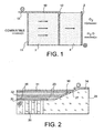
- the figure 1 represents, in section, a portion of the base element, which illustrates the principle used.
- the electrolyte, referenced 3 and 4 occupies most of the element.
- On one side, that is to the right, is on the outer surface of a straight portion of the electrolyte 4, a cathode positioned in a conventional manner.
- the latter is also consists of an inner portion 12, parallel to the outer portion 11, and embedded in the middle of the electrolyte. It is electrically connected to the external part by a connection 10.
- This assembly consisting of the connection 10, the outer portion 11 and the inner portion 12, is electrically connected by a connector 13 to the outside of the element.
- the inner portion 12 of the anode is not made of a plate or a solid layer constituting a mechanically impassable barrier, but unlike a grid.
- the mesh may be round, square, hexagonal or other, allowing the passage of protons and water movements that balance the moisture content of the membrane.
- the anode and, in particular, the grid constituted by the inner portion 12 must be made of a material that allows oxidation of the fuel, such as palladium, platinum or ruthenium, or the like. This internal part therefore allows the fuel, unreacted at the external anode, to react at this level, so that the amount of fuel reaching the cathode is minimized.
- the electrolyte can be any proton conducting polymer, for example Nafion ®.
- the electrodes are preferably platinum-based.
- the fuel may be an alcohol such as, for example, ethanol, methanol or ethylene glycol.
- the few arrows appearing inside the electrolyte 3 and 4 show the fuel migration from the anode to the cathode, and illustrate the limitation of the migration phenomenon by the presence of the internal part of the anode. On the side of the cathode 2, the reaction of protons with oxygen occurs, which produces water.
- the figure 2 refers partially, and in section, to a more concrete embodiment of a fuel cell base element, including its manufacturing process.
- a silicon substrate 25 is used to support the assembly. It has, on the left of the figure, oxygen supply lines 26 perpendicular to the upper surface and an inclined section 27. The entire silicon substrate 25 thus forms a bowl inside which must be made together.
- the first phase of manufacture of the latter consists in etching one or more cuvettes on a surface of the silicon substrate 25.
- figure 2 which is a section, shows the shape of the edge of one of these bowls. These are machined by etching and more specifically by a basic attack, for example with hot potassium hydroxide.
- the second phase consists in depositing, in the vapor phase, on the bottom of the cuvette of the substrate 25, the cathode 20 constituted by a metal collector.
- the thickness of the cathode 20 is of the order of one micrometer.
- the third operation consists in depositing on the cathode 20 an active layer 35 intended to catalyze the oxygen reduction reaction.
- This active layer 35 is a mixture of platinum graphite and a PVDF binder, that is to say polyvinylidene fluoride. This layer is a few microns thick.
- the fourth phase consists in depositing a first portion of the electrolyte 23 which must cover the first active layer 35 to the edge of the bowl constituted by the inclined section 27.
- the electrolyte 23 is a solution of Nafion ® shaped by coating. This layer has a thickness of the order of 20 microns. Spreading can be done by centrifugation, followed by drying.
- the electrolyte 23 may also consist of one of the following products: polyimides, sulphonated polyethersulfones, sulphonated polystyrenes and their sulphonated derivatives, sulphonated polyetherketones and their sulphonated derivatives, sulphonated polybenzoxazoles, polybenzimidazoles and their derivatives, polyarylenes such as para-phenylenes and polyparaxylylenes and their sulfonated derivatives. It can be deposited in the form of a film.
- the next step is to deposit the inner portion 32 of the anode, which is, in this example, made of a single layer not waterproof, but may consist of several layers of different materials. It is deposited in the vapor phase (PVD). This deposition is done under a pressure of 3 mbar in argon plasma with mechanical masking to make the grid.
- This inner part 32 of the anode continues on the side of the bowl, more exactly on the inclined face 27, by an extension of platinum, obtained by the same deposit, constituting an electrical connection 30 with the outer portion 31 also constituting the anode. This makes it possible to obtain electrical homogeneity of the entire anode.
- the next step is to deposit the second part of the electrolyte 23 in the same way as the first part.
- the next step is the deposition by coating the active layer 35 on the anode side consists of platinized carbon, mixed with Nafion ®. Then the outer portion 31 of the anode is obtained by plasma sputtering. It extends to the edge of the bowl, that is to say until the connection 30. Outside the assembly, this layer is extended to form a connector 34, deposited in the vapor phase, of the same way as the inner part 32 of the anode.
- the cuvette shape of the substrate 25 thus makes it possible to connect together two anode layers formed by the outer portion 31 and the inner portion 32 and to constitute the connection 30.
- the deposits of the different layers can also be made by vapor deposition, chemical, spray, coating, dipping or spin coating.
- This invention is particularly applicable to fuel cell systems operating with, as fuel, methanol or other liquid or gaseous fuel capable of migrating through the electrolyte used. It could also apply to batteries using hydrogen, as fuel, in the case of very thin membranes, having a too high gas permeability.
Landscapes
- Chemical & Material Sciences (AREA)
- General Chemical & Material Sciences (AREA)
- Electrochemistry (AREA)
- Chemical Kinetics & Catalysis (AREA)
- Sustainable Development (AREA)
- Sustainable Energy (AREA)
- Life Sciences & Earth Sciences (AREA)
- Manufacturing & Machinery (AREA)
- Engineering & Computer Science (AREA)
- Fuel Cell (AREA)
- Inert Electrodes (AREA)
- Organic Low-Molecular-Weight Compounds And Preparation Thereof (AREA)
- Conductive Materials (AREA)
Description
- L'invention concerne le domaine des piles à combustible du type à membrane échangeuse de protons « PEM » (Proton Exchange Membrane), et en particulier celles de type « DMFC » (Direct Methanol Fuell Cell), utilisant le méthanol ou un autre alcool comme combustible. Il s'agit en particulier des piles à combustible destinées à alimenter des équipements portables, c'est-à-dire légers et très peu encombrants.
- Les piles à combustible utilisent généralement comme combustible l'hydrogène et comme comburant l'oxygène. Or, dans le cas des piles à combustible destinées à alimenter des équipements portables, le volume occupé par le combustible doit être réduit au minimum. Compte tenu du fait que la densité volumique énergétique des combustibles liquides est en général supérieure à celle de l'hydrogène, ceux-ci sont donc choisis comme combustible.
- Comme dans les autres piles à combustible, le combustible est destiné à être oxydé catalytiquement à l'anode pour donner des protons, électrons et produits d'oxydation successifs pouvant aboutir au dioxyde de carbone. L'électrolyte, constitué généralement d'une membrane conductrice protonique du type Nafion®, conduit les protons vers la cathode pour réagir avec l'oxygène et former de l'eau. La difficulté majeure de ce type de pile à combustible réside dans la perméation du combustible, à travers la membrane électrolytique pour réagir à la cathode directement avec l'oxygène. Cette réaction a deux conséquences majeures qui sont la création d'une tension mixte à la cathode, abaissant la tension globale de la pile, et une consommation excessive de combustible diminuant l'autonomie de fonctionnement de l'ensemble. En outre, la migration transversale du combustible dans l'électrolyte est pratiquement impossible à éviter, car le conducteur protonique contient un système aqueux pour favoriser le passage des protons et le combustible diffuse très vite dans ce système aqueux, où il est miscible.
- La demande internationale
WO-01/37357 - le ralentissement de la migration des protons causé par une réaction d'absorption/diffusion/désorption dans la membrane métallique ;
- le blocage des mouvements d'eau dans la membrane et, par conséquent, la création de zones plus sèches et donc moins conductrices ioniquement.
- Le but de l'invention est de remédier à ces inconvénients et de présenter un concept différent pour empêcher le méthanol de traverser la couche d'électrolyte jusqu'à la cathode, tout en ayant pour souci d'augmenter le rendement de la pile en utilisant le méthanol présent dans l'électrolyte.
- A cet effet, l'objet principal de l'invention est un élément de base de pile à combustible comprenant un électrolyte entre une cathode et une anode.
- Selon l'invention, l'anode comprend une partie interne placée de façon noyée dans l'électrolyte et reliée électriquement à une partie externe.
- De préférence, l'électrolyte se trouve sous forme de film ou sous forme de couche.
- Cette partie interne peut être constituée de plusieurs couches de matériaux différents.
- Elle est, de préférence, parallèle à la partie externe.
- La partie interne peut également être constituée d'au moins une mousse.
- La partie interne peut être réalisée, de préférence, sous la forme d'une ou de plusieurs grilles.
- Dans une réalisation préférentielle de l'élément de base selon l'invention, le combustible est un alcool, de préférence, choisi parmi l'éthanol, le méthanol et l'éthylène glycol.
- L'invention et ses différentes caractéristiques seront mieux comprises à la lecture de la description suivante, accompagnée de deux figures qui représentent respectivement :
-
figure 1 , en coupe, le principe général de l'élément de base selon l'invention ; et -
figure 2 , en coupe partielle, une réalisation particulière de l'élément de base selon l'invention. - La manière d'aboutir à l'objectif, ci-dessus énoncé, consiste toujours à faire réagir le combustible, dans l'électrolyte avant qu'il ne parvienne à la cathode.
- La
figure 1 représente, en coupe, une portion de l'élément de base, qui illustre bien le principe utilisé. L'électrolyte, référencé 3 et 4, occupe la majeure partie de l'élément. D'un côté, c'est-à-dire à droite, se trouve, sur la surface externe d'une partie droite de l'électrolyte 4, une cathode positionnée d'une manière conventionnelle. Sur la partie gauche de la surface externe de l'électrolyte 3, se trouve une partie externe 11 de l'anode. Cette dernière est également constituée d'une partie interne 12, parallèle à la partie externe 11, et noyée au milieu de l'électrolyte. Elle est reliée électriquement à la partie externe par une connexion 10. Cet ensemble constitué de la connexion 10, de la partie externe 11 et de la partie interne 12, est relié électriquement par un connecteur 13 à l'extérieur de l'élément. Il est nécessaire de préciser que la partie interne 12 de l'anode n'est pas constituée d'une plaque ou une couche pleine constituant un barrage mécaniquement infranchissable, mais au contraire d'une grille. Celle-ci peut avoir plusieurs formes différentes, les mailles pouvant être rondes, carrées, hexagonales ou autres, permettant le passage des protons et les mouvements d'eau qui équilibrent la teneur en eau de la membrane. L'anode et, en particulier, la grille constituée par la partie interne 12 doit être en un matériau permettant l'oxydation du combustible, tel que le palladium, le platine ou le ruthénium ou autres. Cette partie interne permet donc au combustible, n'ayant pas réagi au niveau de l'anode externe, de réagir à ce niveau, de façon à ce que la quantité de combustible atteignant la cathode soit minimisée. - L'électrolyte peut être n'importe quel polymère conducteur protonique, par exemple le Nafion®. Les électrodes sont de préférence à base de platine. Le combustible peut être un alcool comme, par exemple l'éthanol, le méthanol, l'éthylène glycol.
- Les quelques flèches figurant à l'intérieur de l'électrolyte 3 et 4 montrent la migration du combustible de l'anode vers la cathode, et illustrent la limitation du phénomène de migration par la présence de la partie interne de l'anode. Du côté de la cathode 2, se produit la réaction des protons avec l'oxygène, ce qui produit de l'eau.
- Sur les figures, une seule partie interne 12 de l'anode est prévue. Néanmoins, il est possible d'envisager plusieurs parties internes 12 reliées électriquement à la partie externe 11.
- La
figure 2 fait référence partiellement, et en coupe, à une réalisation plus concrète d'un élément de base de pile à combustible, notamment à son procédé de fabrication. - A cet effet, on utilise un substrat en silicium 25 pour supporter l'ensemble. Celui-ci possède, à la gauche de la figure, des canalisations d'alimentation en oxygène 26, perpendiculaires à la surface supérieure et un pan incliné 27. L'ensemble du substrat en silicium 25 forme donc une cuvette à l'intérieur de laquelle doit être fabriqué l'ensemble.
- La première phase de fabrication de ce dernier consiste à graver une ou plusieurs cuvettes sur une surface du substrat en silicium 25. La
figure 2 , qui est une coupe, montre la forme du bord d'une de ces cuvettes. Ces dernières sont usinées par attaque chimique et plus précisément par une attaque basique, par exemple avec de l'hydroxyde de potassium à chaud. - La deuxième phase consiste à déposer, en phase vapeur, sur le fond de la cuvette du substrat 25, la cathode 20 constituée d'un collecteur métallique. L'épaisseur de la cathode 20 est de l'ordre du micromètre.
- La troisième opération consiste à déposer par enduction sur la cathode 20 une couche active 35 destinée à catalyser la réaction de réduction de l'oxygène. Cette couche active 35 est un mélange de graphite platiné et d'un liant en PVDF, c'est-à-dire polyfluorure de vinylidène. Cette couche est épaisse de quelques micromètres.
- La quatrième phase consiste à déposer une première partie de l'électrolyte 23 qui doit recouvrir la première couche active 35 jusqu'au bord de la cuvette constituée par le pan incliné 27. L'électrolyte 23 est une solution de Nafion® mis en forme par enduction. Cette couche a une épaisseur de l'ordre de 20 µm. L'étalement peut se faire par centrifugation, suivi d'un séchage. L'électrolyte 23 peut être également constitué d'un des produits suivants: les polyimides, les polyéthersulfones sulfonés, les polystyrènes sulfonés et leurs dérivés sulfonés, les polyéthercétones sulfonés et leurs dérivés sulfonés, les polybenzoxazoles sulfonés, les polybenzimidazoles et leurs dérivés, les polyarylènes tels que les paraphénylènes et polyparaxylylènes et leurs dérivés sulfonés. Il peut être déposé sous la forme d'un film.
- L'étape suivante consiste à déposer la partie interne 32 de l'anode, qui est, sur cet exemple, constituée d'une seule couche non étanche, mais peut être constituée de plusieurs couches de matériaux différents. Elle est déposée en phase vapeur (PVD). Ce dépôt se fait sous une pression de 3 mbar en plasma d'argon avec un masquage mécanique pour réaliser la grille. Cette partie interne 32 de l'anode se poursuit sur le côté de la cuvette, plus exactement sur le pan incliné 27, par un prolongement de platine, obtenu par le même dépôt, constituant une connexion électrique 30 avec la partie externe 31 constituant également l'anode. Ceci permet d'obtenir une homogénéité électrique de toute l'anode.
- L'étape suivante consiste à déposer la deuxième partie de l'électrolyte 23 de la même manière que la première partie.
- L'étape suivante est le dépôt par enduction de la couche active 35 côté anode constituée de carbone platiné, mélange à du Nafion®. Puis la partie externe 31 de- L'anode est obtenue par pulvérisation cathodique plasma. Elle se prolonge jusqu'au bord de la cuvette, c'est-à-dire jusqu'à la connexion 30. A l'extérieur de l'ensemble, cette couche se prolonge pour constituer un connecteur 34, déposé en phase vapeur, de la même manière que la partie interne 32 de l'anode. La forme en cuvette du substrat 25 permet ainsi de relier ensemble deux couches anodiques constituées par la partie externe 31 et la partie interne 32 et à constituer la connexion 30.
- Dans l'exemple représenté sur la
figure 2 , une seule partie interne 32 a été représentée. Il est très possible d'envisager que plusieurs parties internes successives soient intercalées dans une couche d'électrolyte plus important. - Les dépôts des différentes couches peuvent également être réalisés par dépôt en phase vapeur, par voie chimique, par pulvérisation, par enduction, par trempage ou dépôt par centrifugation.
- Cette invention s'applique en particulier à des systèmes de piles à combustible fonctionnant avec, comme combustible, du méthanol ou avec un autre combustible liquide ou gazeux susceptible de migrer au travers de l'électrolyte utilisé. Elle pourrait aussi s'appliquer aux piles utilisant l'hydrogène, comme combustible, dans le cas de membranes très fines, ayant une perméabilité aux gaz trop importante.
Claims (9)
- Elément de base de pile à combustible comprenant, un électrolyte (3, 23) entre une anode et une cathode :
caractérisé en ce que l'anode comprend une partie interne (12, 32) placée de façon noyée dans l'électrolyte (3, 23) et reliée électriquement à une partie externe (11, 31) en contact d'un seul côté avec l'électrolyte (23). - Elément de base de pile à combustible selon la revendication 1, caractérisé en ce que l'électrolyte (3, 23) se trouve sous la forme d'un film.
- Elément de base de pile à combustible selon la revendication 1, caractérisé en ce que l'électrolyte (3, 23) se trouve sous la forme d'une couche.
- Elément de base de pile à combustible selon la revendication 1, caractérisé en ce que la partie interne (12, 32) est sensiblement parallèle à la partie externe (31) de l'anode.
- Elément de base de pile à combustible selon la revendication 1 ou 4, caractérisé en ce que la partie interne (32) est constituée d'au moins une grille.
- Elément de base de pile à combustible selon la revendication 1, caractérisé en ce que la partie interne (12, 32) est constituée d'au moins une mousse.
- Elément de base de pile à combustible selon l'une des revendications précédentes, caractérisé en ce que la partie interne (32) est constituée de plusieurs couches de matériaux différents.
- Elément de base selon la revendication 1, caractérisé en ce que le combustible est un alcool.
- Elément de base selon la revendication 8, caractérisé en ce que l'alcool est choisi parmi l'éthanol, le méthanol et l'éthylène glycol.
Applications Claiming Priority (3)
| Application Number | Priority Date | Filing Date | Title |
|---|---|---|---|
| FR0205062 | 2002-04-23 | ||
| FR0205062A FR2838870B1 (fr) | 2002-04-23 | 2002-04-23 | Element de base de pile a combustible limitant la traversee de l'electrolyte par le methanol |
| PCT/FR2003/001250 WO2003092092A2 (fr) | 2002-04-23 | 2003-04-18 | Element de base de pile a combustible limitant la traversee de l'electrolyte par le methanol. |
Publications (2)
| Publication Number | Publication Date |
|---|---|
| EP1497883A2 EP1497883A2 (fr) | 2005-01-19 |
| EP1497883B1 true EP1497883B1 (fr) | 2008-12-03 |
Family
ID=28686285
Family Applications (1)
| Application Number | Title | Priority Date | Filing Date |
|---|---|---|---|
| EP03747147A Expired - Lifetime EP1497883B1 (fr) | 2002-04-23 | 2003-04-18 | Element de base de pile a combustible limitant la traversee de l'electrolyte par le methanol |
Country Status (9)
| Country | Link |
|---|---|
| US (1) | US7169503B2 (fr) |
| EP (1) | EP1497883B1 (fr) |
| JP (1) | JP4768261B2 (fr) |
| CN (1) | CN100539280C (fr) |
| AT (1) | ATE416485T1 (fr) |
| DE (1) | DE60325038D1 (fr) |
| ES (1) | ES2316787T3 (fr) |
| FR (1) | FR2838870B1 (fr) |
| WO (1) | WO2003092092A2 (fr) |
Families Citing this family (11)
| Publication number | Priority date | Publication date | Assignee | Title |
|---|---|---|---|---|
| US20070012244A1 (en) * | 2005-07-15 | 2007-01-18 | Cymbet Corporation | Apparatus and method for making thin-film batteries with soft and hard electrolyte layers |
| US7776478B2 (en) | 2005-07-15 | 2010-08-17 | Cymbet Corporation | Thin-film batteries with polymer and LiPON electrolyte layers and method |
| KR101387855B1 (ko) * | 2005-07-15 | 2014-04-22 | 사임베트 코퍼레이션 | 연질 및 경질 전해질층을 가진 박막 배터리 및 그 제조방법 |
| GB0514581D0 (en) * | 2005-07-15 | 2005-08-24 | Univ Newcastle | Methanol fuel cells |
| WO2007063257A1 (fr) * | 2005-11-30 | 2007-06-07 | Stmicroelectronics Sa | Pile a combustible integree empilable |
| FR2894075A1 (fr) * | 2005-11-30 | 2007-06-01 | St Microelectronics Sa | Support de pile a combustible integree |
| US10658705B2 (en) | 2018-03-07 | 2020-05-19 | Space Charge, LLC | Thin-film solid-state energy storage devices |
| US9853325B2 (en) | 2011-06-29 | 2017-12-26 | Space Charge, LLC | Rugged, gel-free, lithium-free, high energy density solid-state electrochemical energy storage devices |
| US11527774B2 (en) | 2011-06-29 | 2022-12-13 | Space Charge, LLC | Electrochemical energy storage devices |
| US10601074B2 (en) | 2011-06-29 | 2020-03-24 | Space Charge, LLC | Rugged, gel-free, lithium-free, high energy density solid-state electrochemical energy storage devices |
| US11996517B2 (en) | 2011-06-29 | 2024-05-28 | Space Charge, LLC | Electrochemical energy storage devices |
Family Cites Families (15)
| Publication number | Priority date | Publication date | Assignee | Title |
|---|---|---|---|---|
| JPS58115770A (ja) * | 1981-12-26 | 1983-07-09 | Toshiba Corp | 燃料電池 |
| US4664761A (en) * | 1985-12-27 | 1987-05-12 | Uop Inc. | Electrochemical method and apparatus using proton-conducting polymers |
| JPH0622144B2 (ja) * | 1986-04-18 | 1994-03-23 | 三菱電機株式会社 | 燃料電池 |
| JP3271801B2 (ja) * | 1992-09-22 | 2002-04-08 | 田中貴金属工業株式会社 | 高分子固体電解質型燃料電池、該燃料電池の加湿方法、及び製造方法 |
| US5919583A (en) * | 1995-03-20 | 1999-07-06 | E. I. Du Pont De Nemours And Company | Membranes containing inorganic fillers and membrane and electrode assemblies and electrochemical cells employing same |
| US5672438A (en) * | 1995-10-10 | 1997-09-30 | E. I. Du Pont De Nemours And Company | Membrane and electrode assembly employing exclusion membrane for direct methanol fuel cell |
| US5672439A (en) * | 1995-12-18 | 1997-09-30 | Ballard Power Systems, Inc. | Method and apparatus for reducing reactant crossover in an electrochemical fuel cell |
| JP3502508B2 (ja) * | 1996-07-26 | 2004-03-02 | 本田技研工業株式会社 | 直接メタノール型燃料電池 |
| JP3844022B2 (ja) * | 1997-06-09 | 2006-11-08 | 株式会社ジーエス・ユアサコーポレーション | 固体高分子電解質を備えた直接型メタノ−ル燃料電池 |
| JP3774898B2 (ja) * | 1997-06-30 | 2006-05-17 | 株式会社ジーエス・ユアサコーポレーション | 固体高分子電解質を備えた直接型メタノ−ル燃料電池 |
| DE19803132C1 (de) | 1998-01-28 | 1999-04-01 | Forschungszentrum Juelich Gmbh | Brennstoffzelle mit einem protonenleitfähigen Elektrolyten |
| AU2662699A (en) * | 1998-02-10 | 1999-08-23 | California Institute Of Technology | Asymmetric electrodes for direct-feed fuel cells |
| DE19859765A1 (de) * | 1998-12-23 | 2000-06-29 | Forschungszentrum Juelich Gmbh | Elektroden-Elektrolyt-Einheit für eine Brennstoffzelle |
| CA2392115A1 (fr) * | 1999-11-17 | 2001-05-25 | Neah Power Systems, Inc. | Piles a combustible ayant des substrats de silicium et/ou des structures de soutien derivees de sol-gel |
| US7045244B2 (en) * | 2002-06-10 | 2006-05-16 | Hewlett-Packard Development Company, L.P. | Fuel cells utilizing non-porous nanofilm microchannel architecture |
-
2002
- 2002-04-23 FR FR0205062A patent/FR2838870B1/fr not_active Expired - Fee Related
-
2003
- 2003-04-18 CN CNB038004968A patent/CN100539280C/zh not_active Expired - Fee Related
- 2003-04-18 US US10/481,490 patent/US7169503B2/en not_active Expired - Fee Related
- 2003-04-18 DE DE60325038T patent/DE60325038D1/de not_active Expired - Lifetime
- 2003-04-18 AT AT03747147T patent/ATE416485T1/de not_active IP Right Cessation
- 2003-04-18 ES ES03747147T patent/ES2316787T3/es not_active Expired - Lifetime
- 2003-04-18 JP JP2004500348A patent/JP4768261B2/ja not_active Expired - Fee Related
- 2003-04-18 WO PCT/FR2003/001250 patent/WO2003092092A2/fr not_active Ceased
- 2003-04-18 EP EP03747147A patent/EP1497883B1/fr not_active Expired - Lifetime
Also Published As
| Publication number | Publication date |
|---|---|
| FR2838870B1 (fr) | 2004-05-28 |
| EP1497883A2 (fr) | 2005-01-19 |
| ES2316787T3 (es) | 2009-04-16 |
| FR2838870A1 (fr) | 2003-10-24 |
| US20050042499A1 (en) | 2005-02-24 |
| ATE416485T1 (de) | 2008-12-15 |
| WO2003092092A3 (fr) | 2004-11-04 |
| CN100539280C (zh) | 2009-09-09 |
| JP2005524203A (ja) | 2005-08-11 |
| JP4768261B2 (ja) | 2011-09-07 |
| CN1628395A (zh) | 2005-06-15 |
| WO2003092092A2 (fr) | 2003-11-06 |
| DE60325038D1 (de) | 2009-01-15 |
| US7169503B2 (en) | 2007-01-30 |
Similar Documents
| Publication | Publication Date | Title |
|---|---|---|
| WO2003092092A2 (fr) | Element de base de pile a combustible limitant la traversee de l'electrolyte par le methanol. | |
| EP1456902B1 (fr) | Pile a combustible et procede de fabrication d'une telle pile a surface active importante et a volume reduit | |
| WO2002054522A1 (fr) | Procede de fabrication d'un assemblage d'elements de base pour un etage de pile a combustible | |
| EP2559085A1 (fr) | Structuration d'électrode de piles à combustible à membrane échangeuse de protons | |
| EP2248215A1 (fr) | Procede de fabrication d'une pile a combustible en couches minces a oxyde solide dite sofc | |
| EP1997178B1 (fr) | Pile à combustible comportant un ensemble capable de gérer l'eau produite par ladite pile | |
| FR2863777A1 (fr) | Pile a combustible alcaline insensible a la carbonatation. | |
| FR2894077A1 (fr) | Procede de fabrication de pile a combustible en couches minces | |
| FR2819108A1 (fr) | Element de base composite et son joint pour pile a combustible et procede de fabrication de l'ensemble | |
| EP1645006B1 (fr) | Pile a combustible dans laquelle un fluide circule sensiblement parallelement a la membrane electrolytique et procede de fabrication d'une telle pile a combustible | |
| FR2857162A1 (fr) | Pile a combustible comportant des collecteurs de courant integres a l'empilement electrode-membrane-electrode. | |
| EP2856542B1 (fr) | Cathode pour batterie lithium-air, comportant une structure bi-couches de catalyseurs differents et batterie lithium-air comprenant cette cathode | |
| EP1282185A2 (fr) | Procédé de réalisation d'une pile à combustible à géometrie cylindrique | |
| FR2846797A1 (fr) | Module de base monobloc et a relief de pile a combustible miniature et son procede de fabrication | |
| EP3813168B1 (fr) | Pile a combustible adaptee a caracteriser au moins un polluant present dans un gaz reactif | |
| EP1501144B1 (fr) | Cellule de pile à combustible à forte surface active | |
| FR2918799A1 (fr) | Substrat poreux etanche pour piles a combustible planaires et packaging integre. | |
| EP2270914A1 (fr) | Pile à combustible à membrane de purification d'hydrogène integrée | |
| EP2452388B1 (fr) | Méthode et dispositif pour augmenter la durée de vie d'une pile à combustible à membrane échangeuse de protons | |
| FR2959610A1 (fr) | Procede de depot d'une couche catalytique pour pile a combustible | |
| WO2025012385A1 (fr) | Cellule électrochimique à électrode support structurée | |
| WO2025181164A1 (fr) | Unité de cellule mixte à électrode et électrolyte supports et ses procédés de fabrication | |
| FR2814857A1 (fr) | Micropiles a combustible notamment utilisees dans les dispositifs electroniques portables, dans les equipements automobiles et dans les dispositifs de telecommunication | |
| WO2013041781A1 (fr) | Pile à combustible à haute densité d'assemblages membrane-électrodes partageant une cavité fluidique commune | |
| FR2843896A1 (fr) | Substrat poreux contenant une phase metallique a gradient de concentration et procede de fabrication de ce substrat |
Legal Events
| Date | Code | Title | Description |
|---|---|---|---|
| PUAI | Public reference made under article 153(3) epc to a published international application that has entered the european phase |
Free format text: ORIGINAL CODE: 0009012 |
|
| 17P | Request for examination filed |
Effective date: 20031121 |
|
| AK | Designated contracting states |
Kind code of ref document: A2 Designated state(s): AT BE BG CH CY CZ DE DK EE ES FI FR GB GR HU IE IT LI LU MC NL PT SE TR |
|
| RAP1 | Party data changed (applicant data changed or rights of an application transferred) |
Owner name: COMMISSARIAT A L'ENERGIE ATOMIQUE |
|
| RIC1 | Information provided on ipc code assigned before grant |
Ipc: H01M 4/86 20060101ALN20080409BHEP Ipc: H01M 8/10 20060101AFI20080409BHEP |
|
| GRAP | Despatch of communication of intention to grant a patent |
Free format text: ORIGINAL CODE: EPIDOSNIGR1 |
|
| GRAS | Grant fee paid |
Free format text: ORIGINAL CODE: EPIDOSNIGR3 |
|
| GRAA | (expected) grant |
Free format text: ORIGINAL CODE: 0009210 |
|
| AK | Designated contracting states |
Kind code of ref document: B1 Designated state(s): AT BE BG CH CY CZ DE DK EE ES FI FR GB GR HU IE IT LI LU MC NL PT SE TR |
|
| REG | Reference to a national code |
Ref country code: GB Ref legal event code: FG4D Free format text: NOT ENGLISH |
|
| REG | Reference to a national code |
Ref country code: CH Ref legal event code: EP |
|
| REG | Reference to a national code |
Ref country code: IE Ref legal event code: FG4D Free format text: LANGUAGE OF EP DOCUMENT: FRENCH |
|
| REF | Corresponds to: |
Ref document number: 60325038 Country of ref document: DE Date of ref document: 20090115 Kind code of ref document: P |
|
| REG | Reference to a national code |
Ref country code: ES Ref legal event code: FG2A Ref document number: 2316787 Country of ref document: ES Kind code of ref document: T3 |
|
| NLV1 | Nl: lapsed or annulled due to failure to fulfill the requirements of art. 29p and 29m of the patents act | ||
| PG25 | Lapsed in a contracting state [announced via postgrant information from national office to epo] |
Ref country code: NL Free format text: LAPSE BECAUSE OF FAILURE TO SUBMIT A TRANSLATION OF THE DESCRIPTION OR TO PAY THE FEE WITHIN THE PRESCRIBED TIME-LIMIT Effective date: 20081203 |
|
| REG | Reference to a national code |
Ref country code: IE Ref legal event code: FD4D |
|
| PG25 | Lapsed in a contracting state [announced via postgrant information from national office to epo] |
Ref country code: EE Free format text: LAPSE BECAUSE OF FAILURE TO SUBMIT A TRANSLATION OF THE DESCRIPTION OR TO PAY THE FEE WITHIN THE PRESCRIBED TIME-LIMIT Effective date: 20081203 Ref country code: IE Free format text: LAPSE BECAUSE OF FAILURE TO SUBMIT A TRANSLATION OF THE DESCRIPTION OR TO PAY THE FEE WITHIN THE PRESCRIBED TIME-LIMIT Effective date: 20081203 Ref country code: BG Free format text: LAPSE BECAUSE OF FAILURE TO SUBMIT A TRANSLATION OF THE DESCRIPTION OR TO PAY THE FEE WITHIN THE PRESCRIBED TIME-LIMIT Effective date: 20090303 |
|
| PG25 | Lapsed in a contracting state [announced via postgrant information from national office to epo] |
Ref country code: CZ Free format text: LAPSE BECAUSE OF FAILURE TO SUBMIT A TRANSLATION OF THE DESCRIPTION OR TO PAY THE FEE WITHIN THE PRESCRIBED TIME-LIMIT Effective date: 20081203 Ref country code: SE Free format text: LAPSE BECAUSE OF FAILURE TO SUBMIT A TRANSLATION OF THE DESCRIPTION OR TO PAY THE FEE WITHIN THE PRESCRIBED TIME-LIMIT Effective date: 20090303 Ref country code: PT Free format text: LAPSE BECAUSE OF FAILURE TO SUBMIT A TRANSLATION OF THE DESCRIPTION OR TO PAY THE FEE WITHIN THE PRESCRIBED TIME-LIMIT Effective date: 20090504 Ref country code: AT Free format text: LAPSE BECAUSE OF FAILURE TO SUBMIT A TRANSLATION OF THE DESCRIPTION OR TO PAY THE FEE WITHIN THE PRESCRIBED TIME-LIMIT Effective date: 20081203 |
|
| PLBE | No opposition filed within time limit |
Free format text: ORIGINAL CODE: 0009261 |
|
| STAA | Information on the status of an ep patent application or granted ep patent |
Free format text: STATUS: NO OPPOSITION FILED WITHIN TIME LIMIT |
|
| PG25 | Lapsed in a contracting state [announced via postgrant information from national office to epo] |
Ref country code: DK Free format text: LAPSE BECAUSE OF FAILURE TO SUBMIT A TRANSLATION OF THE DESCRIPTION OR TO PAY THE FEE WITHIN THE PRESCRIBED TIME-LIMIT Effective date: 20081203 |
|
| BERE | Be: lapsed |
Owner name: COMMISSARIAT A L'ENERGIE ATOMIQUE Effective date: 20090430 |
|
| 26N | No opposition filed |
Effective date: 20090904 |
|
| REG | Reference to a national code |
Ref country code: CH Ref legal event code: PL |
|
| PG25 | Lapsed in a contracting state [announced via postgrant information from national office to epo] |
Ref country code: CH Free format text: LAPSE BECAUSE OF NON-PAYMENT OF DUE FEES Effective date: 20090430 Ref country code: LI Free format text: LAPSE BECAUSE OF NON-PAYMENT OF DUE FEES Effective date: 20090430 |
|
| PG25 | Lapsed in a contracting state [announced via postgrant information from national office to epo] |
Ref country code: MC Free format text: LAPSE BECAUSE OF NON-PAYMENT OF DUE FEES Effective date: 20090430 |
|
| PG25 | Lapsed in a contracting state [announced via postgrant information from national office to epo] |
Ref country code: BE Free format text: LAPSE BECAUSE OF NON-PAYMENT OF DUE FEES Effective date: 20090430 |
|
| PG25 | Lapsed in a contracting state [announced via postgrant information from national office to epo] |
Ref country code: GR Free format text: LAPSE BECAUSE OF FAILURE TO SUBMIT A TRANSLATION OF THE DESCRIPTION OR TO PAY THE FEE WITHIN THE PRESCRIBED TIME-LIMIT Effective date: 20090304 |
|
| PG25 | Lapsed in a contracting state [announced via postgrant information from national office to epo] |
Ref country code: LU Free format text: LAPSE BECAUSE OF NON-PAYMENT OF DUE FEES Effective date: 20090418 |
|
| PG25 | Lapsed in a contracting state [announced via postgrant information from national office to epo] |
Ref country code: HU Free format text: LAPSE BECAUSE OF FAILURE TO SUBMIT A TRANSLATION OF THE DESCRIPTION OR TO PAY THE FEE WITHIN THE PRESCRIBED TIME-LIMIT Effective date: 20090604 |
|
| PG25 | Lapsed in a contracting state [announced via postgrant information from national office to epo] |
Ref country code: TR Free format text: LAPSE BECAUSE OF FAILURE TO SUBMIT A TRANSLATION OF THE DESCRIPTION OR TO PAY THE FEE WITHIN THE PRESCRIBED TIME-LIMIT Effective date: 20081203 |
|
| PG25 | Lapsed in a contracting state [announced via postgrant information from national office to epo] |
Ref country code: CY Free format text: LAPSE BECAUSE OF FAILURE TO SUBMIT A TRANSLATION OF THE DESCRIPTION OR TO PAY THE FEE WITHIN THE PRESCRIBED TIME-LIMIT Effective date: 20081203 |
|
| PGFP | Annual fee paid to national office [announced via postgrant information from national office to epo] |
Ref country code: FI Payment date: 20130319 Year of fee payment: 11 |
|
| PG25 | Lapsed in a contracting state [announced via postgrant information from national office to epo] |
Ref country code: FI Free format text: LAPSE BECAUSE OF NON-PAYMENT OF DUE FEES Effective date: 20140418 |
|
| REG | Reference to a national code |
Ref country code: FR Ref legal event code: PLFP Year of fee payment: 13 |
|
| PGFP | Annual fee paid to national office [announced via postgrant information from national office to epo] |
Ref country code: DE Payment date: 20150409 Year of fee payment: 13 Ref country code: ES Payment date: 20150423 Year of fee payment: 13 Ref country code: GB Payment date: 20150414 Year of fee payment: 13 |
|
| PGFP | Annual fee paid to national office [announced via postgrant information from national office to epo] |
Ref country code: FR Payment date: 20150430 Year of fee payment: 13 Ref country code: IT Payment date: 20150424 Year of fee payment: 13 |
|
| REG | Reference to a national code |
Ref country code: DE Ref legal event code: R119 Ref document number: 60325038 Country of ref document: DE |
|
| GBPC | Gb: european patent ceased through non-payment of renewal fee |
Effective date: 20160418 |
|
| REG | Reference to a national code |
Ref country code: FR Ref legal event code: ST Effective date: 20161230 |
|
| PG25 | Lapsed in a contracting state [announced via postgrant information from national office to epo] |
Ref country code: FR Free format text: LAPSE BECAUSE OF NON-PAYMENT OF DUE FEES Effective date: 20160502 Ref country code: DE Free format text: LAPSE BECAUSE OF NON-PAYMENT OF DUE FEES Effective date: 20161101 Ref country code: GB Free format text: LAPSE BECAUSE OF NON-PAYMENT OF DUE FEES Effective date: 20160418 |
|
| PG25 | Lapsed in a contracting state [announced via postgrant information from national office to epo] |
Ref country code: IT Free format text: LAPSE BECAUSE OF NON-PAYMENT OF DUE FEES Effective date: 20160418 |
|
| PG25 | Lapsed in a contracting state [announced via postgrant information from national office to epo] |
Ref country code: ES Free format text: LAPSE BECAUSE OF NON-PAYMENT OF DUE FEES Effective date: 20160419 |
|
| REG | Reference to a national code |
Ref country code: ES Ref legal event code: FD2A Effective date: 20181204 |